EP4091757B1 - Verfahren zur behandlung wenigstens einer schicht oder eines bereichs eines bauteils - Google Patents
Verfahren zur behandlung wenigstens einer schicht oder eines bereichs eines bauteils Download PDFInfo
- Publication number
- EP4091757B1 EP4091757B1 EP22162360.6A EP22162360A EP4091757B1 EP 4091757 B1 EP4091757 B1 EP 4091757B1 EP 22162360 A EP22162360 A EP 22162360A EP 4091757 B1 EP4091757 B1 EP 4091757B1
- Authority
- EP
- European Patent Office
- Prior art keywords
- laser beam
- component
- region
- layer
- laser
- Prior art date
- Legal status (The legal status is an assumption and is not a legal conclusion. Google has not performed a legal analysis and makes no representation as to the accuracy of the status listed.)
- Active
Links
Images
Classifications
-
- B—PERFORMING OPERATIONS; TRANSPORTING
- B23—MACHINE TOOLS; METAL-WORKING NOT OTHERWISE PROVIDED FOR
- B23K—SOLDERING OR UNSOLDERING; WELDING; CLADDING OR PLATING BY SOLDERING OR WELDING; CUTTING BY APPLYING HEAT LOCALLY, e.g. FLAME CUTTING; WORKING BY LASER BEAM
- B23K26/00—Working by laser beam, e.g. welding, cutting or boring
- B23K26/0006—Working by laser beam, e.g. welding, cutting or boring taking account of the properties of the material involved
-
- B—PERFORMING OPERATIONS; TRANSPORTING
- B23—MACHINE TOOLS; METAL-WORKING NOT OTHERWISE PROVIDED FOR
- B23K—SOLDERING OR UNSOLDERING; WELDING; CLADDING OR PLATING BY SOLDERING OR WELDING; CUTTING BY APPLYING HEAT LOCALLY, e.g. FLAME CUTTING; WORKING BY LASER BEAM
- B23K26/00—Working by laser beam, e.g. welding, cutting or boring
- B23K26/02—Positioning or observing the workpiece, e.g. with respect to the point of impact; Aligning, aiming or focusing the laser beam
- B23K26/06—Shaping the laser beam, e.g. by masks or multi-focusing
- B23K26/073—Shaping the laser spot
- B23K26/0738—Shaping the laser spot into a linear shape
-
- B—PERFORMING OPERATIONS; TRANSPORTING
- B23—MACHINE TOOLS; METAL-WORKING NOT OTHERWISE PROVIDED FOR
- B23K—SOLDERING OR UNSOLDERING; WELDING; CLADDING OR PLATING BY SOLDERING OR WELDING; CUTTING BY APPLYING HEAT LOCALLY, e.g. FLAME CUTTING; WORKING BY LASER BEAM
- B23K26/00—Working by laser beam, e.g. welding, cutting or boring
- B23K26/08—Devices involving relative movement between laser beam and workpiece
- B23K26/082—Scanning systems, i.e. devices involving movement of the laser beam relative to the laser head
-
- B—PERFORMING OPERATIONS; TRANSPORTING
- B23—MACHINE TOOLS; METAL-WORKING NOT OTHERWISE PROVIDED FOR
- B23K—SOLDERING OR UNSOLDERING; WELDING; CLADDING OR PLATING BY SOLDERING OR WELDING; CUTTING BY APPLYING HEAT LOCALLY, e.g. FLAME CUTTING; WORKING BY LASER BEAM
- B23K26/00—Working by laser beam, e.g. welding, cutting or boring
- B23K26/352—Working by laser beam, e.g. welding, cutting or boring for surface treatment
- B23K26/354—Working by laser beam, e.g. welding, cutting or boring for surface treatment by melting
-
- B—PERFORMING OPERATIONS; TRANSPORTING
- B23—MACHINE TOOLS; METAL-WORKING NOT OTHERWISE PROVIDED FOR
- B23K—SOLDERING OR UNSOLDERING; WELDING; CLADDING OR PLATING BY SOLDERING OR WELDING; CUTTING BY APPLYING HEAT LOCALLY, e.g. FLAME CUTTING; WORKING BY LASER BEAM
- B23K26/00—Working by laser beam, e.g. welding, cutting or boring
- B23K26/50—Working by transmitting the laser beam through or within the workpiece
- B23K26/53—Working by transmitting the laser beam through or within the workpiece for modifying or reforming the material inside the workpiece, e.g. for producing break initiation cracks
-
- B—PERFORMING OPERATIONS; TRANSPORTING
- B23—MACHINE TOOLS; METAL-WORKING NOT OTHERWISE PROVIDED FOR
- B23K—SOLDERING OR UNSOLDERING; WELDING; CLADDING OR PLATING BY SOLDERING OR WELDING; CUTTING BY APPLYING HEAT LOCALLY, e.g. FLAME CUTTING; WORKING BY LASER BEAM
- B23K2103/00—Materials to be soldered, welded or cut
- B23K2103/50—Inorganic materials other than metals or composite materials
- B23K2103/52—Ceramics
-
- B—PERFORMING OPERATIONS; TRANSPORTING
- B23—MACHINE TOOLS; METAL-WORKING NOT OTHERWISE PROVIDED FOR
- B23K—SOLDERING OR UNSOLDERING; WELDING; CLADDING OR PLATING BY SOLDERING OR WELDING; CUTTING BY APPLYING HEAT LOCALLY, e.g. FLAME CUTTING; WORKING BY LASER BEAM
- B23K2103/00—Materials to be soldered, welded or cut
- B23K2103/50—Inorganic materials other than metals or composite materials
- B23K2103/54—Glass
-
- B—PERFORMING OPERATIONS; TRANSPORTING
- B23—MACHINE TOOLS; METAL-WORKING NOT OTHERWISE PROVIDED FOR
- B23K—SOLDERING OR UNSOLDERING; WELDING; CLADDING OR PLATING BY SOLDERING OR WELDING; CUTTING BY APPLYING HEAT LOCALLY, e.g. FLAME CUTTING; WORKING BY LASER BEAM
- B23K2103/00—Materials to be soldered, welded or cut
- B23K2103/50—Inorganic materials other than metals or composite materials
- B23K2103/56—Inorganic materials other than metals or composite materials being semiconducting
Definitions
- the invention relates to a method for treating at least one layer or a region of a component by means of a laser beam to produce an amorphous layer or an amorphous region according to the preamble of claim 1 (see e.g. WO 2019/236616 A1 ).
- a method for treating at least one layer of a component with the features of the preamble of claim 1 is known from DD 217 738 A1 known.
- a laser beam is guided over the surface of the component and the material of the component is melted on the surface.
- the atoms cannot arrange themselves in a regular crystal structure and only have a short-range order, but not a long-range order. To do this, it is necessary to achieve a very high cooling rate of more than 10 6 Kelvin per second.
- the method according to the invention for treating at least one layer or a region of a component to produce an amorphous layer or an amorphous region in the component with the features of claim 1 has the advantage that it can be used to form almost any 3-dimensional structures or shapes of amorphously solidified material in a material of a component that is transparent to the wavelength of the laser beam, without additional cooling measures being required to increase the cooling rate when the material melted by the laser beam solidifies.
- the method according to the invention proposes that the laser beam has laser pulses with a repetition rate in the megahertz or gigahertz range, that a material transparent to the wavelength of the laser beam is used as the material, and that the area of action of the laser beam in the component is achieved by a fixed displacement of the focus area of the laser beam in relation to a direction running in the direction of propagation of the laser beam in the component.
- the invention is based on the idea of keeping the energy input into the material of the component when melting the material so low or limiting it in time that a sufficiently high cooling rate is achieved even without cooling measures, which leads to an amorphous solidification of the material. This is achieved by the fact that only a relatively small amount of heat energy needs to be dissipated due to the low energy input.
- the volume melted by the laser beam is determined by the non-linear focal volume, which can be influenced by the spatial and temporal intensity distribution of the laser pulse. This makes it possible to deposit energy and create an amorphous volume even below the Abbe limit.
- the melted and subsequently solidified volumes mentioned have a diameter, depending on the wavelength of the laser beam, of a few 100 nm to a few micrometers, typically between 500 nm and 5 ⁇ m. It is advantageous if the lateral deviation is less than 10 ⁇ m when moving the laser beam relative to the component.
- tracking of the focal plane is only partially necessary or not necessary, since in many transparent materials the absorbing volume becomes non-transparent or at least temporally non-transparent during solidification, and the absorption of subsequent pulses already takes place at the boundaries of the processing volume, causing it to grow in the direction of the laser beam.
- the laser beam can be applied one after the other to different layers or areas in the component that run in the direction of propagation of the laser beam. This is particularly advantageous if the material does not become opaque during amorphous solidification. This also enables precise coupling of the energy into the area to be melted.
- the laser beam first acts on the layer or area furthest away from the component surface on the side of the laser beam and the subsequent layers or Areas exposed to the laser beam have a successively smaller distance from the component surface.
- repetition rates of the laser pulses between 50 megahertz and 20 gigahertz, preferably 1.6 gigahertz.
- the interval between two laser pulses is between 10 picoseconds and 100 nanoseconds, preferably about 500 picoseconds.
- the thickness of a melted layer or a melted region of the component is less than 10 ⁇ m, preferably less than 2 ⁇ m. This makes it possible to achieve homogeneous amorphous regions or layers over the entire volume.
- the focus diameter of the laser beam is between 1 ⁇ m and 1000 ⁇ m, preferably between 100 ⁇ m and 1000 ⁇ m.
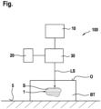
- the single figure shows a schematic representation of a device for generating amorphous volumes on a component.
- the single figure shows a device 100 for producing at least one amorphous volume 1 in the region of a component BT.
- the component BT is shown purely by way of example as a plate-shaped or flat component BT that lies or is positioned on a work surface 5.
- the device 100 has a laser beam device 10, which is designed in the form of an ultrashort pulse laser.
- the laser beam device 10 produces a laser beam LS with pulse packets at a repetition rate of approximately 1.6 gigahertz.
- the pulse packets each comprise approximately between 20 and 1000 laser pulses, preferably approximately between 50 and 250 laser pulses.
- the pulse duration of the laser pulses is between 100 femtoseconds and 50 picoseconds.
- the component BT consists of a material that is transparent to the wavelength of the laser beam LS. This is particularly intended for glasses or monocrystalline insulators and/or semiconductors such as crystalline silicon oxide, which is used to manufacture quartz wafers. Applications with alkali metals that are partially transparent to UV light are also conceivable.
- the energy input which is in the order of one nanojoule to several microjoules per laser pulse, creates an amorphous volume with a diameter of less than 10 ⁇ m.
- the device 10 further comprises an adjustment device 20 for the relative movement between the laser beam LS and the surface O of the Component BT, which is designed as a 5-axis adjustment device 20.
- the component BT or the surface O of the component BT is arranged in operative connection with the surrounding air or possibly with a protective gas atmosphere during the action of the laser beam LS.
- the device 100 comprises an optical device 30 for influencing or guiding the laser beam LS, usually in the form of a scanner.
- the energy input by the laser beam LS is started in the area of the layer S of the material of the component BT that is the greatest distance from the surface O of the component BT on the side facing the laser beam LS or in the direction of propagation of the laser beam LS, i.e. in the area of the deepest layer S.
- this area depending on the lateral extent of the amorphous layer S to be generated, a corresponding lateral movement of the laser beam LS relative to the component BT then takes place.
- the material of the component BT becomes opaque during amorphous solidification, the 3-dimensional structure of volume 1 builds up on the previously solidified layer S in the direction of the surface O after solidification and subsequent repeated energy input.
- the focus can also be set to the area of the layer S closest to the surface O.
Landscapes
- Physics & Mathematics (AREA)
- Engineering & Computer Science (AREA)
- Optics & Photonics (AREA)
- Plasma & Fusion (AREA)
- Mechanical Engineering (AREA)
- Chemical & Material Sciences (AREA)
- Chemical Kinetics & Catalysis (AREA)
- General Chemical & Material Sciences (AREA)
- Oil, Petroleum & Natural Gas (AREA)
- Laser Beam Processing (AREA)
Description
- Die Erfindung betrifft ein Verfahren zur Behandlung wenigstens einer Schicht oder eines Bereichs eines Bauteil mittels eines Laserstrahls zur Erzeugung einer amorphen Schicht oder eines amorphen Bereichs entsprechend dem Oberbegriff des Anspruchs 1 (siehe z.B.
WO 2019/236616 A1 ). - Ein Verfahren zur Behandlung wenigstens einer Schicht eines Bauteils mit den Merkmalen des Oberbegriffs des Anspruchs 1 ist aus der
DD 217 738 A1 - Aus der
WO 2019/236616 A1 ist eine Laserbearbeitungsvorrichtung zur Bearbeitung eines Werkstückes bekannt. DieUS 2009/0280623 A1 offenbart ein Verfahren zur Herstellung eines Halbleiter-Wafers. Aus derUS 2017/0189999 A1 ist ein Verfahren und eine Vorrichtung zur Unterbrechung der Ausbreitung eines einfallenden Risses durch ein transparentes Material bekannt. - Das erfindungsgemäße Verfahren zur Behandlung wenigstens einer Schicht oder eines Bereichs eines Bauteils zur Erzeugung einer amorphen Schicht oder eines amorphen Bereichs in dem Bauteil mit den Merkmalen des Anspruchs 1 hat den Vorteil, dass es dazu verwendet werden kann, nahezu beliebige 3-dimensionale-Strukturen bzw. Formen von amorph erstarrtem Material in einem für die Wellenlänge des Laserstrahls transparenten Material eines Bauteils auszubilden, ohne dass hierzu zusätzliche Kühlmaßnahmen zur Erhöhung der Abkühlgeschwindigkeit beim Erstarren des durch den Laserstrahl aufgeschmolzenen Materials erforderlich sind.
- Hierzu schlägt es das erfindungsgemäße Verfahren gemäß der Lehre des Anspruchs 1 vor, dass der Laserstrahl Laserimpulse mit einer Repetitionsrate im Megaherz- oder Gigaherz-Bereich aufweist, dass als Material ein für die Wellenlänge des Laserstrahls transparentes Material verwendet wird, und dass der Einwirkbereich des Laserstrahls in dem Bauteil durch eine Festverlegung des Fokusbereichs des Laserstrahls in Bezug zur einer in Ausbreitungsrichtung des Laserstrahls im Bauteil verlaufenden Richtung erfolgt.
- Der Erfindung liegt die Idee zugrunde, den Energieeintrag in das Material des Bauteils beim Aufschmelzen des Materials derart gering zu halten bzw. zeitlich zu beschränken, dass auch ohne Kühlmaßnahmen eine hinreichend große Abkühlgeschwindigkeit erzielt wird, die zu einer amorphen Erstarrung des Materials führt. Dies wird dadurch bewirkt, dass durch den geringen Energieeintrag auch nur eine relativ geringe Wärmeenergiemenge abzuführen ist. Zur Erzeugung der amorphen Erstarrung des Materials ist es erforderlich, dass beim Erstarren der aufgeschmolzenen Schicht oder des aufgeschmolzenen Bereichs sich die Atome nicht in einer regelmäßigen Kristallstruktur anordnen können, sodass lediglich eine Nahordnung, nicht aber eine Fernordnung der Atome vorhanden ist. Dazu ist es erforderlich, dass eine sehr hohe Abkühlgeschwindigkeit von mehr 106 K pro Sekunde erzielt wird. Dies wird durch die räumlich stark lokalisierte Absorption und Wärmeeinbringung bei der kurzzeitigen Anwendung einer sehr hohen Repetitionsrate der Laserimpulse ermöglicht, wodurch Abkühlraten von mehr als 106 K pro Sekunde, vorzugsweise mehr als 109 K pro Sekunde gegenüber dem restlichen, nicht erwärmten Material erzielbar sind.
- Das von dem Laserstrahl aufgeschmolzene Volumen wird durch das nichtlineare fokale Volumen bestimmt, welches sich durch die räumliche und zeitliche Intensitätsverteilung des Laserpulses beeinflussen lässt. Somit ist eine Energiedeponierung und Erzeugung eines amorphen Volumens auch unterhalb des Abbe-Limits möglich. Die erwähnten aufgeschmolzenen und anschließend erstarrten Volumina weisen einen Durchmesser, abhängig von der Wellenlänge des Laserstrahls, von einigen 100 nm bis wenigen Mikrometern, typischerweise zwischen 500 nm bis 5 µm, auf. Von Vorteil ist es, wenn beim Relativbewegen des Laserstrahls zum Bauteil die laterale Abweichung weniger als 10 µm beträgt. Dabei ist eine Nachführung der Fokusebene (in einer in Ausbreitungsrichtung des Laserstrahls verlaufenden Richtung) bei transparenten Materialien nur bedingt bzw. nicht notwendig, da bei vielen transparenten Materialien das absorbierende Volumen bei der Erstarrung intransparent oder zumindest zeitlich intransparent wird, und die Absorption nachfolgender Pulse bereits an den Grenzen des Bearbeitungsvolumens stattfindet, wodurch dieses in Richtung des Laserstrahls wächst.
- Vorteilhafte Weiterbildungen des erfindungsgemäßen Verfahrens zur Behandlung wenigstens einer Schicht oder eines Bereichs eines Bauteils sind in den Unteransprüchen aufgeführt.
- Zur Erzeugung einer 3-dimensionalen amorphen Struktur innerhalb des Bauteils kann es vorgesehen sein, dass der Laserstrahl nacheinander auf verschiedene, in Ausbreitungsrichtung des Laserstrahls verlaufende Schichten oder Bereiche im Bauteil einwirkt. Dies ist vor allem dann vorteilhaft, wenn bei der amorphen Erstarrung des Materials dieses nicht intransparent wird. Außerdem wird dadurch eine präzise Einkopplung der Energie in den aufzuschmelzenden Bereich ermöglicht.
- Hierzu ist es besonders bevorzugt vorgesehen, dass der Laserstrahl zunächst auf die von der Bauteiloberfläche auf der Seite des Laserstrahls am weitesten entfernte Schicht oder Bereich einwirkt und die nachfolgenden Schichten oder Bereiche, auf die der Laserstrahl einwirkt, sukzessiv einen geringeren Abstand zur Bauteiloberfläche aufweisen.
- Besonders bevorzugt sind Repetitionsraten der Laserimpulse zwischen 50 Megahertz und 20 Gigahertz, vorzugsweise 1,6 Gigahertz.
- Weiterhin finden bevorzugt Pulspakete mit 10 bis 1000 Laserimpulsen, vorzugsweise zwischen 50 bis 200 Laserimpulsen, Verwendung.
- Der Abstand zwischen zwei Laserimpulsen beträgt zwischen 10 Pikosekunden und 100 Nanosekunden, vorzugsweise etwa 500 Pikosekunden.
- Bevorzugt ist es darüber hinaus, wenn die Dicke einer aufgeschmolzenen Schicht oder eines aufgeschmolzenen Bereichs des Bauteils weniger als 10 µm, vorzugsweise weniger als 2 µm, beträgt. Dadurch lassen sich über das gesamte Volumen homogene amorphe Bereiche bzw. Schichten erzielen.
- Weiterhin ist es von Vorteil, wenn der Fokusdurchmesser des Laserstrahls zwischen 1 µm und 1000 µm, vorzugsweise zwischen 100 µm und 1000 µm, beträgt.
- Die einzige Figur zeigt in einer schematischen Darstellung eine Vorrichtung zur Erzeugung amorpher Volumina an einem Bauteil.
- In der einzigen Figur ist eine Vorrichtung 100 zur Erzeugung wenigstens eines amorphen Volumens 1 im Bereich eines Bauteils BT dargestellt. Das Bauteil BT ist rein beispielhaft als plattenförmiges bzw. ebenes Bauteil BT dargestellt, das auf einer Arbeitsfläche 5 liegt bzw. positioniert ist.
- Zur Erzeugung des amorphen Volumens 1 innerhalb des Bauteils BT weist die Vorrichtung 100 eine Laserstrahleinrichtung 10 auf, die in Form eines Ultrakurzpulslasers ausgebildet ist. Die Laserstrahleinrichtung 10 erzeugt einen Laserstrahl LS mit Pulspaketen bei einer Repetitionsrate von etwa 1,6 Gigahertz. Die Pulspakete umfassen dabei jeweils etwa zwischen 20 und 1000 Laserimpulsen, vorzugsweise etwa zwischen 50 und 250 Laserimpulsen. Die Pulsdauer der Laserimpulse beträgt zwischen 100 Femtosekunden und 50 Pikosekunden.
- Das Bauteil BT besteht aus einem für die Wellenlänge des Laserstrahls LS transparentem Material. Gedacht ist hier insbesondere an Gläser bzw. monokristalline Isolatoren und/oder Halbleiter wie kristallines Siliziumoxid, das der Herstellung von Quarz-Wafern dient. Auch sind Anwendungen bei Alkalimetallen denkbar, die teilweise für UV-Licht transparent sind.
- Der Energieeintrag, der beispielsweise in der Größenordnung von einem Nanojoule bis einigen Mikrojoule pro Laserimpuls liegt, erzeugt ein amorphes Volumen mit einem Durchmesser von weniger als 10 µm.
- Die Vorrichtung 10 umfasst darüber hinaus eine Verstelleinrichtung 20 zur Relativbewegung zwischen dem Laserstrahl LS und der Oberfläche O des Bauteils BT, die als 5-Achs-Verstelleinrichtung 20 ausgebildet ist. Das Bauteil BT bzw. die Oberfläche O des Bauteils BT ist während der Einwirkung des Laserstrahls LS in Wirkverbindung mit der umgebenden Luft oder ggf. mit einer Schutzgasatmosphäre angeordnet. Weiterhin umfasst die Vorrichtung 100 eine Optikeinrichtung 30 zur Beeinflussung bzw. Führung des Laserstrahls LS, üblicherweise in Form eines Scanners.
- Zur Erzeugung des Volumens 1 wird er Energieeintrag durch den Laserstrahl LS im Bereich derjenigen Schicht S des Materials des Bauteils BT begonnen, der von der Oberfläche O des Bauteils BT auf der dem Laserstrahl LS zugewandten Seite bzw. in Ausbreitungsrichtung des Laserstrahls LS betrachtet den größten Abstand aufweist, d.h. im Bereich der tiefsten Schicht S. In diesem Bereich findet dann, je nach lateraler Ausdehnung der zu erzeugenden amorphen Schicht S, anschließend eine entsprechende seitliche Bewegung des Laserstrahls LS relativ zum Bauteil BT statt. Falls das Material des Bauteils BT beim amorphen Erstarren intransparent wird, baut sich nach er Erstarrung und anschließendem wiederholten Energieeintrag die 3-dimensionale Struktur des Volumens 1 auf der zuvor erstarrten Schicht S in Richtung zur Oberfläche O aus. Alternativ kann der Fokus auch auf den Bereich der in Richtung der Oberfläche O nächstliegenden Schicht S eingestellt werden.
Claims (8)
- Verfahren zur Behandlung wenigstens einer Schicht (S) oder eines Bereichs eines Bauteils (BT), bei dem ein Laserstrahl (LS) auf die wenigstens eine Schicht (S) oder den Bereich einwirkt und das Material des Bauteils (BT) im Einwirkbereich des Laserstrahls (LS) derart aufschmelzt, dass bei oder durch Abkühlung das aufgeschmolzene Material amorph erstarrt,
dadurch gekennzeichnet,
dass der Laserstrahl (LS) Laserimpulse mit einer Repetitionsrate im Megahertz- oder Gigahertz-Bereich aufweist, dass als Material für das Bauteil (BT) ein für die Wellenlänge des Laserstrahls (LS) transparentes Material verwendet wird, und dass der Einwirkbereich des Laserstrahls (LS) durch eine Festlegung des Fokusbereichs des Laserstrahls (LS) in Richtung einer in Ausbreitungsrichtung des Laserstrahls (LS) im Bauteil (BT) verlaufenden Richtung erfolgt. - Verfahren nach Anspruch 1,
dadurch gekennzeichnet,
dass zur Erzeugung einer 3-dimensionalen amorphen Struktur bzw. Volumens (1) im Bauteil (BT) der Laserstrahl (LS) nacheinander auf verschiedene, in Ausbreitungsrichtung des Laserstrahls (LS) verlaufende Schichten (S) oder Bereiche im Bauteil (BT) einwirkt. - Verfahren nach Anspruch 2,
dadurch gekennzeichnet,
dass der Laserstrahl (LS) zunächst auf die von der Oberfläche (O) des Bauteils (BT) auf der Seite des Laserstrahls (LS) am weitesten entfernte Schicht (S) oder Bereich einwirkt und die nachfolgenden Schichten (S) oder Bereiche, auf die der Laserstrahl (LS) einwirkt, sukzessiv einen geringeren Abstand zur Oberfläche (O) des Bauteils (BT) aufweisen. - Verfahren nach einem der Ansprüche 1 bis 3,
dadurch gekennzeichnet,
dass die Repetitionsrate zwischen 50 Megahertz und 20 Gigahertz, vorzugsweise 1,6 Gigahertz, beträgt. - Verfahren nach einem der Ansprüche 1 bis 4,
dadurch gekennzeichnet,
dass Pulspakete mit 10 bis 1000 Laserimpulsen erzeugt werden, vorzugsweise Pulspakete mit 50 bis 250 Laserimpulsen. - Verfahren nach einem der Ansprüche 1 bis 5,
dadurch gekennzeichnet,
dass der Abstand zwischen zwei Laserimpulsen zwischen 10 Pikosekunden und 100 Nanosekunden, vorzugsweise etwa 500 Pikosekunden, beträgt. - Verfahren nach einem der Ansprüche 1 bis 6,
dadurch gekennzeichnet,
dass die Dicke einer aufgeschmolzenen Schicht (S) oder eines aufgeschmolzenen Bereichs des Bauteils (BT) weniger als 10 Mikrometer, vorzugsweise weniger als 2 Mikrometer, beträgt. - Verfahren nach einem der Ansprüche 1 bis 7,
dadurch gekennzeichnet,
dass der Fokusdurchmesser des Laserstrahls (LS) zwischen 1µm und 1000µm, vorzugsweise zwischen 100µm und 1000µm beträgt.
Applications Claiming Priority (1)
| Application Number | Priority Date | Filing Date | Title |
|---|---|---|---|
| DE102021203609.0A DE102021203609A1 (de) | 2021-04-13 | 2021-04-13 | Verfahren zur Behandlung wenigstens einer Schicht oder eines Bereichs eines Bauteils und Vorrichtung zum Durchführen des Verfahrens |
Publications (2)
| Publication Number | Publication Date |
|---|---|
| EP4091757A1 EP4091757A1 (de) | 2022-11-23 |
| EP4091757B1 true EP4091757B1 (de) | 2024-12-25 |
Family
ID=80785133
Family Applications (1)
| Application Number | Title | Priority Date | Filing Date |
|---|---|---|---|
| EP22162360.6A Active EP4091757B1 (de) | 2021-04-13 | 2022-03-16 | Verfahren zur behandlung wenigstens einer schicht oder eines bereichs eines bauteils |
Country Status (2)
| Country | Link |
|---|---|
| EP (1) | EP4091757B1 (de) |
| DE (1) | DE102021203609A1 (de) |
Family Cites Families (4)
| Publication number | Priority date | Publication date | Assignee | Title |
|---|---|---|---|---|
| DD217738A1 (de) | 1983-10-03 | 1985-01-23 | Ilmenau Tech Hochschule | Verfahren zum oberflaechenbehandeln von teilen |
| JP5365063B2 (ja) * | 2008-05-07 | 2013-12-11 | 株式会社Sumco | シリコンウェーハの製造方法 |
| EP3536440A1 (de) * | 2014-07-14 | 2019-09-11 | Corning Incorporated | Glasartikel mit einem defektweg |
| CN112074370B (zh) * | 2018-06-05 | 2023-03-14 | 伊雷克托科学工业股份有限公司 | 激光加工设备、其操作方法以及使用其加工工件的方法 |
-
2021
- 2021-04-13 DE DE102021203609.0A patent/DE102021203609A1/de active Pending
-
2022
- 2022-03-16 EP EP22162360.6A patent/EP4091757B1/de active Active
Also Published As
| Publication number | Publication date |
|---|---|
| EP4091757A1 (de) | 2022-11-23 |
| DE102021203609A1 (de) | 2022-10-13 |
Similar Documents
| Publication | Publication Date | Title |
|---|---|---|
| EP3854513B1 (de) | System zur asymmetrischen optischen strahlformung | |
| EP3302864B1 (de) | Verfahren und vorrichtung zur herstellung eines strukturierten elements durch materialabtragende bearbeitung mit gepulster lasersstrahlung | |
| DE102004024643A1 (de) | Werkstückteilungsverfahren unter Verwendung eines Laserstrahls | |
| DE102016205918A1 (de) | Wafer-Herstellungsverfahren | |
| DE102016201779A1 (de) | Wafer-Herstellungsverfahren | |
| DE112007000608T5 (de) | Laserbearbeitungsverfahren und Laserbearbeitungssystem | |
| EP1871566B1 (de) | Verfahren zum feinpolieren/-strukturieren wärmeempflindlicher dielektrischer materialien mittels laserstrahlung | |
| EP4380903B1 (de) | Verfahren und vorrichtung zur laserbearbeitung eines werkstücks | |
| DE102016212318A1 (de) | Wafer-Herstellungsverfahren | |
| DE102020108247A1 (de) | Grossvolumiges entfernen von material durch laser-unterstütztes ätzen | |
| EP3854515A1 (de) | Verfahren zur bearbeitung sprödharter materialien | |
| DE102016213420A1 (de) | Verfahren und Vorrichtung zum generativen Herstellen eines Bauteils | |
| EP4263113A1 (de) | Vorrichtung und verfahren zum trennen eines materials | |
| EP3875436B1 (de) | Verfahren zum vorbereiten und/oder durchführen des trennens eines substratelements und substratteilelement | |
| DE19646332C2 (de) | Verfahren zur Veränderung des optischen Verhaltens an der Oberfläche und/oder innerhalb eines Werkstückes mittels eines Lasers | |
| DE102005047082A1 (de) | Verfahren zur Mikrostrukturierung von Oberflächen eines Werkstücks und seine Verwendung | |
| EP4091757A1 (de) | Verfahren zur behandlung wenigstens einer schicht oder eines bereichs eines bauteils und vorrichtung zum durchführen des verfahrens | |
| DE102008025354A1 (de) | Einrichtung zur Erzeugung von mikrostrukturierten Funktionsoberflächen auf Substraten mit wenigstens einem Laser | |
| WO2012159963A1 (de) | Verfahren zur homogenisierung des laserstrahlprofils bei prozessen unter einsatz eines flüssigkeitsstrahlgeführten lasers und entsprechende vorrichtung | |
| DE102013002222A1 (de) | Verfahren zur Modifikation der Oberfläche eines Metalls | |
| EP4263114A1 (de) | Vorrichtung und verfahren zum trennen eines materials | |
| WO2022128242A1 (de) | Vorrichtung und verfahren zum trennen und abfasen eines materials | |
| DE102019220188A1 (de) | Verfahren und Vorrichtung zur Oberflächenbehandlung von metallischen Oberflächen | |
| DE102007020704B4 (de) | Einrichtung für die Bearbeitung eines Werkstückes mit einem Laserstrahl | |
| DE102019220167A1 (de) | Verfahren zum Polieren und/oder Glätten einer metallischen Oberfläche von einem Werkstück sowie Werkstück mit polierter und/oder geglätteter Oberfläche |
Legal Events
| Date | Code | Title | Description |
|---|---|---|---|
| PUAI | Public reference made under article 153(3) epc to a published international application that has entered the european phase |
Free format text: ORIGINAL CODE: 0009012 |
|
| STAA | Information on the status of an ep patent application or granted ep patent |
Free format text: STATUS: THE APPLICATION HAS BEEN PUBLISHED |
|
| AK | Designated contracting states |
Kind code of ref document: A1 Designated state(s): AL AT BE BG CH CY CZ DE DK EE ES FI FR GB GR HR HU IE IS IT LI LT LU LV MC MK MT NL NO PL PT RO RS SE SI SK SM TR |
|
| STAA | Information on the status of an ep patent application or granted ep patent |
Free format text: STATUS: REQUEST FOR EXAMINATION WAS MADE |
|
| 17P | Request for examination filed |
Effective date: 20230523 |
|
| RBV | Designated contracting states (corrected) |
Designated state(s): AL AT BE BG CH CY CZ DE DK EE ES FI FR GB GR HR HU IE IS IT LI LT LU LV MC MK MT NL NO PL PT RO RS SE SI SK SM TR |
|
| STAA | Information on the status of an ep patent application or granted ep patent |
Free format text: STATUS: EXAMINATION IS IN PROGRESS |
|
| 17Q | First examination report despatched |
Effective date: 20231113 |
|
| GRAP | Despatch of communication of intention to grant a patent |
Free format text: ORIGINAL CODE: EPIDOSNIGR1 |
|
| STAA | Information on the status of an ep patent application or granted ep patent |
Free format text: STATUS: GRANT OF PATENT IS INTENDED |
|
| RIC1 | Information provided on ipc code assigned before grant |
Ipc: B23K 103/00 20060101ALN20240710BHEP Ipc: B23K 26/354 20140101ALI20240710BHEP Ipc: B23K 26/53 20140101ALI20240710BHEP Ipc: B23K 26/082 20140101ALI20240710BHEP Ipc: B23K 26/073 20060101ALI20240710BHEP Ipc: B23K 26/00 20140101AFI20240710BHEP |
|
| RIC1 | Information provided on ipc code assigned before grant |
Ipc: B23K 103/00 20060101ALN20240722BHEP Ipc: B23K 26/354 20140101ALI20240722BHEP Ipc: B23K 26/53 20140101ALI20240722BHEP Ipc: B23K 26/082 20140101ALI20240722BHEP Ipc: B23K 26/073 20060101ALI20240722BHEP Ipc: B23K 26/00 20140101AFI20240722BHEP |
|
| INTG | Intention to grant announced |
Effective date: 20240731 |
|
| GRAS | Grant fee paid |
Free format text: ORIGINAL CODE: EPIDOSNIGR3 |
|
| GRAA | (expected) grant |
Free format text: ORIGINAL CODE: 0009210 |
|
| STAA | Information on the status of an ep patent application or granted ep patent |
Free format text: STATUS: THE PATENT HAS BEEN GRANTED |
|
| AK | Designated contracting states |
Kind code of ref document: B1 Designated state(s): AL AT BE BG CH CY CZ DE DK EE ES FI FR GB GR HR HU IE IS IT LI LT LU LV MC MK MT NL NO PL PT RO RS SE SI SK SM TR |
|
| REG | Reference to a national code |
Ref country code: GB Ref legal event code: FG4D Free format text: NOT ENGLISH |
|
| REG | Reference to a national code |
Ref country code: CH Ref legal event code: EP |
|
| REG | Reference to a national code |
Ref country code: DE Ref legal event code: R096 Ref document number: 502022002471 Country of ref document: DE |
|
| REG | Reference to a national code |
Ref country code: IE Ref legal event code: FG4D Free format text: LANGUAGE OF EP DOCUMENT: GERMAN |
|
| REG | Reference to a national code |
Ref country code: LT Ref legal event code: MG9D |
|
| PG25 | Lapsed in a contracting state [announced via postgrant information from national office to epo] |
Ref country code: HR Free format text: LAPSE BECAUSE OF FAILURE TO SUBMIT A TRANSLATION OF THE DESCRIPTION OR TO PAY THE FEE WITHIN THE PRESCRIBED TIME-LIMIT Effective date: 20241225 |
|
| PG25 | Lapsed in a contracting state [announced via postgrant information from national office to epo] |
Ref country code: FI Free format text: LAPSE BECAUSE OF FAILURE TO SUBMIT A TRANSLATION OF THE DESCRIPTION OR TO PAY THE FEE WITHIN THE PRESCRIBED TIME-LIMIT Effective date: 20241225 |
|
| PG25 | Lapsed in a contracting state [announced via postgrant information from national office to epo] |
Ref country code: BG Free format text: LAPSE BECAUSE OF FAILURE TO SUBMIT A TRANSLATION OF THE DESCRIPTION OR TO PAY THE FEE WITHIN THE PRESCRIBED TIME-LIMIT Effective date: 20241225 |
|
| PG25 | Lapsed in a contracting state [announced via postgrant information from national office to epo] |
Ref country code: NO Free format text: LAPSE BECAUSE OF FAILURE TO SUBMIT A TRANSLATION OF THE DESCRIPTION OR TO PAY THE FEE WITHIN THE PRESCRIBED TIME-LIMIT Effective date: 20250325 |
|
| PG25 | Lapsed in a contracting state [announced via postgrant information from national office to epo] |
Ref country code: LV Free format text: LAPSE BECAUSE OF FAILURE TO SUBMIT A TRANSLATION OF THE DESCRIPTION OR TO PAY THE FEE WITHIN THE PRESCRIBED TIME-LIMIT Effective date: 20241225 Ref country code: GR Free format text: LAPSE BECAUSE OF FAILURE TO SUBMIT A TRANSLATION OF THE DESCRIPTION OR TO PAY THE FEE WITHIN THE PRESCRIBED TIME-LIMIT Effective date: 20250326 |
|
| PG25 | Lapsed in a contracting state [announced via postgrant information from national office to epo] |
Ref country code: RS Free format text: LAPSE BECAUSE OF FAILURE TO SUBMIT A TRANSLATION OF THE DESCRIPTION OR TO PAY THE FEE WITHIN THE PRESCRIBED TIME-LIMIT Effective date: 20250325 |
|
| REG | Reference to a national code |
Ref country code: NL Ref legal event code: MP Effective date: 20241225 |
|
| PG25 | Lapsed in a contracting state [announced via postgrant information from national office to epo] |
Ref country code: NL Free format text: LAPSE BECAUSE OF FAILURE TO SUBMIT A TRANSLATION OF THE DESCRIPTION OR TO PAY THE FEE WITHIN THE PRESCRIBED TIME-LIMIT Effective date: 20241225 |
|
| PG25 | Lapsed in a contracting state [announced via postgrant information from national office to epo] |
Ref country code: SM Free format text: LAPSE BECAUSE OF FAILURE TO SUBMIT A TRANSLATION OF THE DESCRIPTION OR TO PAY THE FEE WITHIN THE PRESCRIBED TIME-LIMIT Effective date: 20241225 |
|
| PG25 | Lapsed in a contracting state [announced via postgrant information from national office to epo] |
Ref country code: PL Free format text: LAPSE BECAUSE OF FAILURE TO SUBMIT A TRANSLATION OF THE DESCRIPTION OR TO PAY THE FEE WITHIN THE PRESCRIBED TIME-LIMIT Effective date: 20241225 |
|
| PGFP | Annual fee paid to national office [announced via postgrant information from national office to epo] |
Ref country code: DE Payment date: 20250522 Year of fee payment: 4 |
|
| PG25 | Lapsed in a contracting state [announced via postgrant information from national office to epo] |
Ref country code: ES Free format text: LAPSE BECAUSE OF FAILURE TO SUBMIT A TRANSLATION OF THE DESCRIPTION OR TO PAY THE FEE WITHIN THE PRESCRIBED TIME-LIMIT Effective date: 20241225 |
|
| PG25 | Lapsed in a contracting state [announced via postgrant information from national office to epo] |
Ref country code: IS Free format text: LAPSE BECAUSE OF FAILURE TO SUBMIT A TRANSLATION OF THE DESCRIPTION OR TO PAY THE FEE WITHIN THE PRESCRIBED TIME-LIMIT Effective date: 20250425 |
|
| PG25 | Lapsed in a contracting state [announced via postgrant information from national office to epo] |
Ref country code: PT Free format text: LAPSE BECAUSE OF FAILURE TO SUBMIT A TRANSLATION OF THE DESCRIPTION OR TO PAY THE FEE WITHIN THE PRESCRIBED TIME-LIMIT Effective date: 20250428 |
|
| PG25 | Lapsed in a contracting state [announced via postgrant information from national office to epo] |
Ref country code: EE Free format text: LAPSE BECAUSE OF FAILURE TO SUBMIT A TRANSLATION OF THE DESCRIPTION OR TO PAY THE FEE WITHIN THE PRESCRIBED TIME-LIMIT Effective date: 20241225 |
|
| PG25 | Lapsed in a contracting state [announced via postgrant information from national office to epo] |
Ref country code: RO Free format text: LAPSE BECAUSE OF FAILURE TO SUBMIT A TRANSLATION OF THE DESCRIPTION OR TO PAY THE FEE WITHIN THE PRESCRIBED TIME-LIMIT Effective date: 20241225 |
|
| PG25 | Lapsed in a contracting state [announced via postgrant information from national office to epo] |
Ref country code: SK Free format text: LAPSE BECAUSE OF FAILURE TO SUBMIT A TRANSLATION OF THE DESCRIPTION OR TO PAY THE FEE WITHIN THE PRESCRIBED TIME-LIMIT Effective date: 20241225 |
|
| PG25 | Lapsed in a contracting state [announced via postgrant information from national office to epo] |
Ref country code: CZ Free format text: LAPSE BECAUSE OF FAILURE TO SUBMIT A TRANSLATION OF THE DESCRIPTION OR TO PAY THE FEE WITHIN THE PRESCRIBED TIME-LIMIT Effective date: 20241225 |
|
| PG25 | Lapsed in a contracting state [announced via postgrant information from national office to epo] |
Ref country code: IT Free format text: LAPSE BECAUSE OF FAILURE TO SUBMIT A TRANSLATION OF THE DESCRIPTION OR TO PAY THE FEE WITHIN THE PRESCRIBED TIME-LIMIT Effective date: 20241225 |
|
| PG25 | Lapsed in a contracting state [announced via postgrant information from national office to epo] |
Ref country code: SE Free format text: LAPSE BECAUSE OF FAILURE TO SUBMIT A TRANSLATION OF THE DESCRIPTION OR TO PAY THE FEE WITHIN THE PRESCRIBED TIME-LIMIT Effective date: 20241225 |
|
| REG | Reference to a national code |
Ref country code: DE Ref legal event code: R097 Ref document number: 502022002471 Country of ref document: DE |
|
| PG25 | Lapsed in a contracting state [announced via postgrant information from national office to epo] |
Ref country code: DK Free format text: LAPSE BECAUSE OF FAILURE TO SUBMIT A TRANSLATION OF THE DESCRIPTION OR TO PAY THE FEE WITHIN THE PRESCRIBED TIME-LIMIT Effective date: 20241225 |
|
| PG25 | Lapsed in a contracting state [announced via postgrant information from national office to epo] |
Ref country code: MC Free format text: LAPSE BECAUSE OF FAILURE TO SUBMIT A TRANSLATION OF THE DESCRIPTION OR TO PAY THE FEE WITHIN THE PRESCRIBED TIME-LIMIT Effective date: 20241225 |
|
| REG | Reference to a national code |
Ref country code: CH Ref legal event code: H13 Free format text: ST27 STATUS EVENT CODE: U-0-0-H10-H13 (AS PROVIDED BY THE NATIONAL OFFICE) Effective date: 20251023 |
|
| PLBE | No opposition filed within time limit |
Free format text: ORIGINAL CODE: 0009261 |
|
| STAA | Information on the status of an ep patent application or granted ep patent |
Free format text: STATUS: NO OPPOSITION FILED WITHIN TIME LIMIT |
|
| PG25 | Lapsed in a contracting state [announced via postgrant information from national office to epo] |
Ref country code: LU Free format text: LAPSE BECAUSE OF NON-PAYMENT OF DUE FEES Effective date: 20250316 |
|
| 26N | No opposition filed |
Effective date: 20250926 |
|
| REG | Reference to a national code |
Ref country code: BE Ref legal event code: MM Effective date: 20250331 |
|
| PG25 | Lapsed in a contracting state [announced via postgrant information from national office to epo] |
Ref country code: FR Free format text: LAPSE BECAUSE OF NON-PAYMENT OF DUE FEES Effective date: 20250331 |
|
| PG25 | Lapsed in a contracting state [announced via postgrant information from national office to epo] |
Ref country code: BE Free format text: LAPSE BECAUSE OF NON-PAYMENT OF DUE FEES Effective date: 20250331 |
|
| PG25 | Lapsed in a contracting state [announced via postgrant information from national office to epo] |
Ref country code: CH Free format text: LAPSE BECAUSE OF NON-PAYMENT OF DUE FEES Effective date: 20250331 |
|
| PG25 | Lapsed in a contracting state [announced via postgrant information from national office to epo] |
Ref country code: IE Free format text: LAPSE BECAUSE OF NON-PAYMENT OF DUE FEES Effective date: 20250316 |
|
| PGFP | Annual fee paid to national office [announced via postgrant information from national office to epo] |
Ref country code: AT Payment date: 20260301 Year of fee payment: 5 |