EP4091495B1 - Connection assembly and wearable device - Google Patents
Connection assembly and wearable device Download PDFInfo
- Publication number
- EP4091495B1 EP4091495B1 EP21207946.1A EP21207946A EP4091495B1 EP 4091495 B1 EP4091495 B1 EP 4091495B1 EP 21207946 A EP21207946 A EP 21207946A EP 4091495 B1 EP4091495 B1 EP 4091495B1
- Authority
- EP
- European Patent Office
- Prior art keywords
- clamping
- groove
- connection assembly
- clamping part
- connection
- Prior art date
- Legal status (The legal status is an assumption and is not a legal conclusion. Google has not performed a legal analysis and makes no representation as to the accuracy of the status listed.)
- Active
Links
Images



Classifications
-
- A—HUMAN NECESSITIES
- A44—HABERDASHERY; JEWELLERY
- A44C—PERSONAL ADORNMENTS, e.g. JEWELLERY; COINS
- A44C5/00—Bracelets; Wrist-watch straps; Fastenings for bracelets or wrist-watch straps
- A44C5/0007—Bracelets specially adapted for other functions or with means for attaching other articles
-
- A—HUMAN NECESSITIES
- A44—HABERDASHERY; JEWELLERY
- A44C—PERSONAL ADORNMENTS, e.g. JEWELLERY; COINS
- A44C5/00—Bracelets; Wrist-watch straps; Fastenings for bracelets or wrist-watch straps
- A44C5/14—Bracelets; Wrist-watch straps; Fastenings for bracelets or wrist-watch straps characterised by the way of fastening to a wrist-watch or the like
Definitions
- watchbands or wristbands acting as connection carriers need not only to conform to human engineering but also need to be disassembled conveniently during use of the smartwatches or smart bracelets.
- US 2016/0037876 A1 discloses a locking assembly for an attachment system of an electronic device. More specifically, embodiments of US 2016/0037876 A1 are directed to an attachment unit that is configured to be inserted and removed from a housing of a consumer product. The attachment unit and/or the housing includes a catch member or other such locking assembly configured to releasably secure the attachment unit within the housing.
- the disclosure relates to the technical field of wearable devices, and relates to a connection assembly and a wearable device.
- connection assembly including:
- the second clamping member further includes: an elastic member which is connected to the second clamping part and located on a side, facing away from the opening, of the second clamping part, and the elastic member is elastically deformable by an external force to drive the second clamping part to be extended or retracted from the opening.
- connection assembly further includes:
- the wall which is in contact with the sliding part, in the sliding groove, is a slope.
- the fixing part of the first clamping member includes: a through-hole through which the operating part passes to control the sliding part to move in the sliding groove.
- the elastic member when an external force acts on the operating part, the elastic member is in a compression state, and the second clamping part is separated from the second clamping groove; and when the external force is removed, the elastic member is in an extension state and the second clamping part is clamped into the first clamping groove.
- the first clamping part includes at least one first stop block
- a wearable device including:
- the device body includes: a first clamping groove and a second clamping groove;
- connection assemblies which are connected to two opposite ends of the device body;
- the wearable device includes a smartwatch; and the device body is a watch face.
- the wearable device includes a smart bracelet; and the device body includes a bracelet chip or a bracelet display screen.
- connection carriers in existing wearable devices are generally connected by integration or by lugs and spring bars.
- connection achieved by the integration cannot meet the demand on repairing or replacing the connection carriers; and connection achieved by the lugs and the spring bars has the problem that the disassembly is inconvenient.
- Fig. 1 is a schematic diagram I illustrating a connection assembly according to an embodiment. As shown in Fig. 1 which is a schematic diagram of disassembly of a connection assembly, the connection assembly includes:
- Fig. 2 is a schematic diagram II illustrating a connection assembly according to an embodiment, the support member 101, the first clamping member 104 and the second clamping member 107 form the connection assembly together.
- connection assembly may be a separate assembly for enabling an interconnection function, for example, the support member of the connection assembly may be connected to a band-shaped connector and the first and second clamping parts are connected to the to-be-connected body to achieve a detachable connection between the band-shaped connector and the to-be-connected body.
- connection assembly may be a part of the band-shaped connector, i.e., the connection assembly may also be integrally formed with the band-shaped connector.
- the connection assembly can be used to connect the watchband and a watch face in the smartwatch; and alternatively, the band-shaped connector is a wristband of a smart bracelet, the wristband has a curved shape, the connection assembly is used to connect the wristband and a bracelet display screen in the smart bracelet. In some embodiments, when the band-shaped connector has a curved shape, the connection assembly may also be set to have a curved shape.
- the support member may be set to be in a curved shape.
- Fig. 3 is a schematic diagram illustrating the support member 101 according to an embodiment. As shown in Fig. 3 , walls on two sides of the accommodating groove 103 in the support body 102 may extend to form extension parts 301, and a curved shape is formed based on the extension parts 301 and side walls on the two sides of the accommodating groove 103. Correspondingly, the fixing part 105 and the first clamping part 106 of the first clamping member 104 may together form a curved shape.
- the curved shape formed by the extension parts on the support member and the side walls on the two sides of the accommodating groove has the same curving angle as the curved shape formed by the fixing part and the first clamping part of the first clamping member, so that the fixing part is totally matched with the support member when the fixing part and the support member are buckled.
- connection assembly when a to-be-connected object is a watch face, the connection assembly is detachably connected to the watch face; when a to-be-connected object is a bracelet display screen, the connection assembly is detachably connected to the bracelet display screen; and when a to-be-connected object is a chip and/or display screen of a smart ring, the connection assembly is detachably connected to the smart ring.
- the second clamping member can be placed in the accommodating groove of the support member and the fixing part of the first clamping member is buckled with the support member, so that the second clamping member can be placed in the accommodating space formed by the fixing part and the accommodating groove.
- the second clamping part of the second clamping member is arranged in a direction of the opening of the accommodating space, so that the second clamping part can be extended or retracted from the opening of the accommodating space.
- the fixing part and the support member may be fixed after the fixing part is buckled with the support member.
- screw holes may be formed in the fixing part and the support member respectively, and then screws pass through the screw holes in the fixing part and the support member respectively, to fix the fixing part and the support member together.
- clamping structures cooperated mutually on the fixing part and the support member respectively, and the fixing between the fixing part and the support member is achieved by the clamping structures.
- the fixing between the fixing part and the support member may be achieved by an injection molding process or a welding process, or by other removable means, which is not limited herein.
- the first clamping part may be clamped into or separated from the first clamping groove in the to-be connected body by an external force.
- a first clamping groove may be formed in the watch face, and in the implementation process, the first clamping part may be aligned with the first clamping groove and is inserted into the first clamping groove, or the first clamping part may be extracted from the first clamping groove to be separated from the first clamping groove.
- a depth of the first clamping groove is the same as a length of the first clamping part.
- a clamping face of the first clamping part is parallel to a display face of the to-be-connected body.
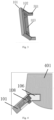
- Fig. 4 is a schematic diagram illustrating clamping of a first clamping member and a to-be-connected body according to an embodiment. As shown in Fig. 4 , the first clamping part 106 may be clamped into a first clamping groove of a to-be-connected body 401, and the second clamping part 108 is located in the accommodating space.
- the first clamping part may be pushed directly into the first clamping groove by an external force, the first clamping part may be also inserted into the first clamping groove by other tools or buttons, for example, an elastic member may be arranged on a side, facing away from a clamping direction, of the first clamping part, and the insertion and extraction of the first clamping part may be controlled by the elastic member, which is not limited herein.
- the to-be-connected body is further provided with a second clamping groove
- the second clamping part extends from the accommodating space to the second clamping groove when the second clamping part is aligned with the opening of the accommodating space.
- the second clamping part may be separated from the second clamping groove when the second clamping part retracts into the accommodating space.
- a depth of the second clamping groove is the same as a length of the second clamping part. In other embodiments, the clamping face of the second clamping part is not parallel to the display face of the to-be-connected body.
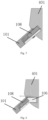
- Fig. 5 is a schematic diagram illustrating clamping of a second clamping member and a to-be-connected body according to an embodiment.
- the second clamping part 108 may be clamped into a second clamping groove of the to-be connected body 401.
- the second clamping part can be pushed directly into the second clamping groove by an external force, and the second clamping part may be also inserted into the second clamping groove by other tools or buttons, for example, an elastic member may be arranged on a side, facing away from a clamping direction, of the second clamping part, and the insertion and extraction of the second clamping part may be controlled by the elastic member, which is not limited herein.
- the second clamping part may be controlled to retract into the accommodating space first, the first clamping part is aligned with the first clamping groove, the first clamping part is inserted into the first clamping groove, and after the first clamping part is inserted into the first clamping groove, the second clamping part is controlled to extend until the second clamping part is inserted into the second clamping groove to connect the connection assembly to the to-be-connected body.
- Fig. 6 is a schematic diagram illustrating extraction of a connection assembly according to an embodiment, as shown in Fig. 6 , a direction of extraction of the second clamping part 108 is the same as a direction of an opening of the second clamping groove, and a direction of extraction of the first clamping part 106 is the same as a direction of an opening of the first clamping groove.
- the first clamping member and the second clamping member are arranged respectively, the first clamping part of the first clamping member is clamped into or separated from the first clamping groove of the to-be-connected body by the external force, the second clamping part of the second clamping member is extendable and retractable, so that the second clamping part can be clamped into or separated from the second clamping groove of the to-be-connected body, and the clamping face of the first clamping part and the clamping face of the second clamping part are located at the different planes, so that the detachable connection between the connection assembly and the to-be-connected body may be achieved by the external force and the mutual cooperation of the first clamping member and the second clamping member.
- the disclosure Compared with the mutual cooperation of multiple components such as a hook, a spring and a pull rod in the related art, the disclosure has simpler design of the mutual cooperation of the first clamping member and the second clamping member and has more convenient disassembly.
- the connection assembly in the disclosure it needs to respectively provide the clamping grooves, which are adaptive to the first clamping part and the second clamping part, in the to-be-connected body, without requiring additional hardware support, so that the operation is easy, and the commonality is high.
- the second clamping member 107 further includes: an elastic member 701, being connected to the second clamping part 108, and located on a side, facing away from the opening of the accommodating space, of the second clamping part 108.
- the elastic member 701 is elastically deformable by an external force to drive the second clamping part 108 to be extended or retracted from the opening.
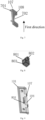
- Fig. 7 is a schematic diagram illustrating a second clamping member according to an embodiment.
- the second clamping member 107 includes the elastic member 701 and the second clamping part 108.
- the elastic member 701 includes springs, clips, or other components, which elastically deform by an external force, which is not limited herein.
- one elastic member or a plurality of elastic members may be arranged on the second clamping part.
- the plurality of elastic members may be respectively arranged on the side, facing away from the opening of the accommodating space, of the second clamping part at intervals, and spacing distances between the respective elastic members may be the same to keep the second clamping part stable in the extension or retraction process.
- the extension and retraction of the second clamping part may be controlled based on deformation of the elastic member by arranging the elastic member on the second clamping part. For example, as shown in Fig. 6 , when the elastic member is in a compression state, the second clamping part retracts into the accommodating space, and as shown in Fig. 5 , when the elastic member is in an extension state, the second clamping part extends into the second clamping groove.
- the extension and retraction of the second clamping part by elastic deformation of the elastic member may improve the use convenience of the connection assembly as compared to the extension and retraction of the second clamping part controlled by direct use of an external force.
- connection assembly further includes:
- Fig. 8 is a schematic diagram illustrating a slider according to an embodiment.
- the slider 801 includes the operating part 802 and the sliding part 803, and during assembly, the sliding part 803 of the slider 801 may be arranged inside the sliding groove 702 of the second clamping member 107 in Fig. 7.
- Fig. 9 is a schematic diagram III illustrating a connection assembly according to an embodiment. As shown in Fig. 9 , the sliding part of the slider 801 is in the sliding groove of the second clamping member 107, and when the second clamping member 107 is arranged in the accommodating space, the operating part of the slider 801 may extend to the outside of the first clamping member 104, so that a user controls the sliding part by the operating part conveniently.
- a volume of the sliding part is greater than that of the operating part.
- the fixing part of the first clamping member includes a through-hole through which the operating part passes to control the sliding part to move in the sliding groove.
- a through-hole is provided in the fixing part of the first clamping part, so that the operating part may pass through the through-hole to control the sliding part to move in the sliding groove.
- a size of the sliding part is larger than a diameter of the through-hole.
- the size of the sliding part includes a length and a width of the sliding part.
- Fig. 10 is a schematic diagram IV illustrating a connection assembly according to an embodiment.
- the operating part of the slider 801 may extend out through the through-hole in the fixing part of the first clamping part, and in the use process, the sliding part may be controlled by the operating part to move in a direction of an arrow shown in Fig. 10 to control the elastic deformation of the elastic member, so as to provide operation convenience for a user.
- the elastic deformation of the elastic member can be controlled by the slider, and thus the extension and retraction of the second clamping part is controlled, so as to save more efforts.
- the through-hole is arranged, and the operating part of the slider extends to the outside of the first clamping member by the through-hole, so that the operation convenience can be provided for a user.
- a wall, which is in contact with the sliding part, in the sliding groove, is a slope.
- a wall, which is in contact with the sliding part, in the sliding groove is a slope.
- the sliding part due to the limited volume of the accommodating space, when the sliding part is arranged in the sliding groove, if the sliding part is pushed by the operating part in a first direction indicated in Fig. 7 , the sliding part generates an extrusion force on the second clamping part, the extrusion force is applied to the elastic member by the body of the second clamping part, and at the moment, the elastic member is compressed to drive the second clamping part to retract in a direction facing away from the opening.
- the sliding part Upon removal of the external force applied by the operating part, the sliding part automatically moves in a second direction opposite to the first direction due to the elastic action of the elastic member to achieve a reset effect.
- the wall, which is in contact with the sliding part, in the sliding groove is set to be the slope to control the elastic member to extend or retract conveniently, and the automatic reset of the slider without the external force can reduce the operating force to be applied by a user as compared to the manual reset of the slider, so as to improve the user experience.
- the elastic member when an external force acts on the operating part, the elastic member is in a compression state, and the second clamping part is separated from the second clamping groove. When the external force is removed, the elastic member is in an extension state, and the second clamping part is clamped into the first clamping groove.
- FIG. 11 is a schematic diagram V illustrating a connection assembly according to an embodiment, and as shown in Fig. 11 , the second clamping part 108 retracts into the accommodating space.
- Fig. 12 is a schematic diagram illustrating insertion of a first clamping part according to an embodiment. As shown in Fig. 12 , the first clamping part may be aligned with the first clamping groove and the connection assembly may move until the first clamping part is inserted into the first clamping groove.
- the external force applied to the operating part may be removed, and at the moment, the slider is reset and the second clamping part extends into the second clamping groove to achieve the clamping of the connection assembly and the to-be-connected body.
- Fig. 13 is a schematic diagram VI illustrating a connection assembly according to an embodiment, and as shown Fig. 13 , after the external force applied to the operating part is removed, the second clamping part extends to the second clamping groove and the slider 801 is reset.
- the first clamping part includes at least one first stop block
- the second clamping part includes at least one second stop block.
- the first and second stop blocks are arranged at intervals.
- first stop blocks there may be a plurality of first stop blocks, and correspondingly, there also may be a plurality of second stop blocks.
- first clamping part may be provided with three first stop blocks
- second clamping part may be provided with two second stop blocks
- two spacer regions are formed between the three first stop blocks
- the two second stop blocks of the second clamping part are arranged in the two spacer regions at intervals.
- the two second stop blocks of the second clamping part can be extended or retracted in the two spacer regions through the opening of the accommodating space.
- a support part may also be arranged on the second clamping member and used to support the second clamping part when the second clamping part extends out.
- a support part 1001 may be arranged on the second clamping member.
- the support part may include at least one support block and the number of the support block is the same as the number of the second stop block, and each support block is used to support one second stop block.
- An embodiment of the disclosure also provides a wearable device, including:
- the device body may be the to-be-connected body of any one of the above embodiments. It should be noted that the band-shaped connector, the device body, and the connection assembly are connected to form the wearing loop, which facilitates that a user wears the wearable device and conforms to the human engineering.
- the device body includes a first clamping groove and a second clamping groove.
- the first clamping part of the first clamping member is clamped into the first clamping groove by an external force
- the second clamping part of the second clamping member is clamped into the second clamping groove when in an extension state.
- An opening of the second clamping groove and an opening of the first clamping groove are in different directions.
- the first clamping part can be clamped into or separated from the first clamping groove in the device body by an external force.
- a first clamping groove may be formed in the watch face, and in the implementation process, the first clamping part may be aligned with the first clamping groove and is inserted into the first clamping groove, or the first clamping part may be extracted from the first clamping groove to be separated from the first clamping groove.
- a depth of the first clamping groove is the same as a length of the first clamping part.
- a clamping face of the first clamping part is parallel to a display face of the device body.
- the device body is further provided with a second clamping groove
- the second clamping part extends from the accommodating space to the second clamping groove when the second clamping part is aligned with the opening of the accommodating space.
- the second clamping part may be separated from the second clamping groove when the second clamping part retracts into the accommodating space.
- a depth of the second clamping groove is the same as a length of the second clamping part. In other embodiments, the clamping face of the second clamping part is not parallel to the display face of the device body.
- the second clamping part may be controlled to retract into the accommodating space first, the first clamping part is aligned with the first clamping groove, the first clamping part is inserted into the first clamping groove, and after the first clamping part is inserted into the first clamping groove, the second clamping part is controlled to extend until the second clamping part is inserted into the second clamping groove to connect the connection assembly to the device body.
- the disclosure has simpler design of the mutual cooperation of the first clamping member and the second clamping member and has more convenient disassembly.
- it needs to respectively provide the clamping grooves, which are adaptive to the first clamping part and the second clamping part, on the device body, without requiring additional hardware support, so that the operation is easy, the commonality is high, and in the use process, a user can rapidly change different band-shaped connectors.
- the band-shaped connector includes: a first connection part and a second connection part, which are respectively located at two opposite ends of the band-shaped connector.
- the first connection part is connected to a support member of one of the connection assemblies
- the second connection part is connected to a support member of the other connection assembly.
- connection between the first and second connection parts and the support members of the connection assemblies may be achieved by clamping, or by fixing, which is not limited herein.
- connection assembly there may be one connection assembly.
- the connection assembly may be located at one end of the device body, the first connection part of the band-shaped connector is connected to a support member of the connection assembly, and the second connection part is connected to the other end of the device body.
- the number of the connection assembly may be set, and is not limited herein.
- the wearable device includes a smartwatch; the device body is a watch face.
- the wearable device includes a smart bracelet; and the device body includes: a bracelet chip or a bracelet display screen.
Landscapes
- Clamps And Clips (AREA)
Description
- With the development of wearable devices and the needs of users, smartwatches or smart bracelets have become popular smart wearable electronic devices, watchbands or wristbands acting as connection carriers need not only to conform to human engineering but also need to be disassembled conveniently during use of the smartwatches or smart bracelets.
- During use, a user has higher requirements not only on the functionality and performance of an electronic device, but also on accessories of connection carriers. The connection carriers are prone to damage during repeated use. Specifically chain-type metal watchbands and plastic watchbands with diversified appearances need to be replaced frequently, and additionally, connection carriers in different styles also need to be replaced frequently due to the pursuit of personalized styles by users.
US 2016/0037876 A1 discloses a locking assembly for an attachment system of an electronic device. More specifically, embodiments ofUS 2016/0037876 A1 are directed to an attachment unit that is configured to be inserted and removed from a housing of a consumer product. The attachment unit and/or the housing includes a catch member or other such locking assembly configured to releasably secure the attachment unit within the housing. - The disclosure relates to the technical field of wearable devices, and relates to a connection assembly and a wearable device.
- According to a first aspect of the disclosure, a connection assembly is provided, including:
- a support member, including: a support body and an accommodating groove on the support body;
- a first clamping member, including: a fixing part and a first clamping part, the fixing part and the support member being buckled to form an accommodating space with the accommodating groove, the accommodating space having an opening, and the first clamping part is adapted to be detachably clamped into a first clamping groove of a to-be-connected body by an external force;
- a second clamping member, including: a second clamping part which is at least partially arranged in the accommodating space and can be extended or retracted from the opening of the accommodating space to be clamped into or separated from a second clamping groove; and
- a clamping face of the first clamping part and a clamping face of the second clamping part are in different planes.
- According to the invention, the second clamping member further includes:
an elastic member which is connected to the second clamping part and located on a side, facing away from the opening, of the second clamping part, and the elastic member is elastically deformable by an external force to drive the second clamping part to be extended or retracted from the opening. - According to the invention, the connection assembly further includes:
- a slider, including: an operating part and a sliding part;
- the second clamping member further including:
- a sliding groove, and the sliding part of the slider is in the sliding groove, the operating part can drive the sliding part to move in the sliding groove by an external force to generate an extrusion force to a wall of the sliding groove, and the extrusion force is transmitted to the elastic member by a body of the second clamping part to cause the elastic member to elastically deform.
- Optionally, the wall, which is in contact with the sliding part, in the sliding groove, is a slope.
- Optionally, the fixing part of the first clamping member includes: a through-hole through which the operating part passes to control the sliding part to move in the sliding groove.
- Optionally, when an external force acts on the operating part, the elastic member is in a compression state, and the second clamping part is separated from the second clamping groove; and when the external force is removed, the elastic member is in an extension state and the second clamping part is clamped into the first clamping groove.
- Optionally, the first clamping part includes at least one first stop block;
- the second clamping part includes at least one second stop block; and
- the first stop block and the second stop block are arranged at intervals.
- According to a second aspect of the disclosure, a wearable device is provided, including:
- a device body;
- a band-shaped connector;
- the connection assembly according to the invention, a support member of the connection assembly being connected to the band-shaped connector, and a first clamping member and a second clamping member of the connection assembly being connected to the device body;
- in a wearing state, the connection assembly, the band-shaped connector and the device body form a wearing loop.
- Optionally, the device body includes: a first clamping groove and a second clamping groove;
- a first clamping part of the first clamping member is clamped into the first clamping groove by an external force;
- a second clamping part of the second clamping member is clamped into the second clamping groove when in an extension state; and
- an opening of the second clamping groove and an opening of the first clamping groove are in different direction.
- Optionally, there are two connection assemblies which are connected to two opposite ends of the device body;
- the band-shaped connector includes: a first connection part and a second connection part, which are located at two opposite ends of the band-shaped connector respectively; and
- in the wearing state of the wearable device, the first connection part is connected to a support member of one of the two connection assemblies, and the second connection part is connected to a support member of the other one of the two connection assemblies.
- Optionally, the wearable device includes a smartwatch; and the device body is a watch face.
- Optionally, the wearable device includes a smart bracelet; and the device body includes a bracelet chip or a bracelet display screen.
- It should be understood that both the foregoing general description and the following detailed description are explanatory only and cannot limit the disclosure.
- The accompanying drawings herein, which are incorporated in and constitute a part of the description, illustrate embodiments consistent with the disclosure and, together with the description, serve to explain the principles of the disclosure.
-
Fig. 1 is a schematic diagram I illustrating a connection assembly according to an embodiment. -
Fig. 2 is a schematic diagram II illustrating a connection assembly according to an embodiment. -
Fig. 3 is a schematic diagram illustrating a support member according to an embodiment. -
Fig. 4 is a schematic diagram illustrating clamping of a first clamping member and a to-be-connected body according to an embodiment. -
Fig. 5 is a schematic diagram illustrating clamping of a second clamping member and a to-be-connected body according to an embodiment. -
Fig. 6 is a schematic diagram illustrating extraction of a connection assembly according to an embodiment. -
Fig. 7 is a schematic diagram illustrating a second clamping member according to an embodiment. -
Fig. 8 is a schematic diagram illustrating a slider according to an embodiment. -
Fig. 9 is a schematic diagram III illustrating a connection assembly according to an embodiment. -
Fig. 10 is a schematic diagram IV illustrating a connection assembly according to an embodiment. -
Fig. 11 is a schematic diagram V illustrating a connection assembly according to an embodiment. -
Fig. 12 is a schematic diagram illustrating insertion of a first clamping part according to an embodiment. -
Fig. 13 is a schematic diagram VI illustrating a connection assembly according to an embodiment. - Embodiments will be described in detail herein, and examples of the embodiments are illustrated in the accompanying drawings. When the following description refers to accompanying drawings, the same numerals in different drawings refer to the same or similar elements unless otherwise indicated. The implementations described in the following examples do not represent all implementations consistent with the disclosure. On the contrary, they are examples of devices and methods consistent with some aspects of the disclosure.
- The connection carriers in existing wearable devices are generally connected by integration or by lugs and spring bars. However, the connection achieved by the integration cannot meet the demand on repairing or replacing the connection carriers; and connection achieved by the lugs and the spring bars has the problem that the disassembly is inconvenient.
-
Fig. 1 is a schematic diagram I illustrating a connection assembly according to an embodiment. As shown inFig. 1 which is a schematic diagram of disassembly of a connection assembly, the connection assembly includes: - a
support member 101, including: asupport body 102 and anaccommodating groove 103 on thesupport body 102; - a
first clamping member 104, including: a fixingpart 105 and afirst clamping part 106, the fixingpart 105 and thesupport member 101 being buckled to form an accommodating space with theaccommodating groove 103, the accommodating space having an opening, and thefirst clamping part 106 is detachable clamped into a first clamping groove of a to-be-connected body by an external force; - a
second clamping member 107, including: asecond clamping part 108 which is at least partially arranged in the accommodating space and can be extended or retracted from the opening of the accommodating space to be clamped into or separated from a second clamping groove of the to-be-connected boy; and - a clamping face of the
first clamping part 106 and a clamping face of thesecond clamping part 108 are in different planes. -
Fig. 2 is a schematic diagram II illustrating a connection assembly according to an embodiment, thesupport member 101, thefirst clamping member 104 and thesecond clamping member 107 form the connection assembly together. - In some embodiments, the connection assembly may be a separate assembly for enabling an interconnection function, for example, the support member of the connection assembly may be connected to a band-shaped connector and the first and second clamping parts are connected to the to-be-connected body to achieve a detachable connection between the band-shaped connector and the to-be-connected body. In other embodiments, the connection assembly may be a part of the band-shaped connector, i.e., the connection assembly may also be integrally formed with the band-shaped connector.
- By taking the band-shaped connector being a watchband of a smartwatch as an example, the watchband has a curved shape, the connection assembly can be used to connect the watchband and a watch face in the smartwatch; and alternatively, the band-shaped connector is a wristband of a smart bracelet, the wristband has a curved shape, the connection assembly is used to connect the wristband and a bracelet display screen in the smart bracelet. In some embodiments, when the band-shaped connector has a curved shape, the connection assembly may also be set to have a curved shape.
- In some embodiments, the support member may be set to be in a curved shape.
Fig. 3 is a schematic diagram illustrating thesupport member 101 according to an embodiment. As shown inFig. 3 , walls on two sides of theaccommodating groove 103 in thesupport body 102 may extend to formextension parts 301, and a curved shape is formed based on theextension parts 301 and side walls on the two sides of theaccommodating groove 103. Correspondingly, the fixingpart 105 and thefirst clamping part 106 of thefirst clamping member 104 may together form a curved shape. - In some embodiments, the curved shape formed by the extension parts on the support member and the side walls on the two sides of the accommodating groove has the same curving angle as the curved shape formed by the fixing part and the first clamping part of the first clamping member, so that the fixing part is totally matched with the support member when the fixing part and the support member are buckled.
- In some embodiments, when a to-be-connected object is a watch face, the connection assembly is detachably connected to the watch face; when a to-be-connected object is a bracelet display screen, the connection assembly is detachably connected to the bracelet display screen; and when a to-be-connected object is a chip and/or display screen of a smart ring, the connection assembly is detachably connected to the smart ring.
- It should be noted that during assembly of the connection assembly, the second clamping member can be placed in the accommodating groove of the support member and the fixing part of the first clamping member is buckled with the support member, so that the second clamping member can be placed in the accommodating space formed by the fixing part and the accommodating groove. Here, the second clamping part of the second clamping member is arranged in a direction of the opening of the accommodating space, so that the second clamping part can be extended or retracted from the opening of the accommodating space.
- In some embodiments, the fixing part and the support member may be fixed after the fixing part is buckled with the support member. For example, screw holes may be formed in the fixing part and the support member respectively, and then screws pass through the screw holes in the fixing part and the support member respectively, to fix the fixing part and the support member together. In other embodiments, it is also possible to arrange clamping structures cooperated mutually on the fixing part and the support member respectively, and the fixing between the fixing part and the support member is achieved by the clamping structures. In other embodiments, the fixing between the fixing part and the support member may be achieved by an injection molding process or a welding process, or by other removable means, which is not limited herein.
- In an embodiment of the disclosure, the first clamping part may be clamped into or separated from the first clamping groove in the to-be connected body by an external force. By taking the to-be-connected body being a watch face as an example, a first clamping groove may be formed in the watch face, and in the implementation process, the first clamping part may be aligned with the first clamping groove and is inserted into the first clamping groove, or the first clamping part may be extracted from the first clamping groove to be separated from the first clamping groove. In some embodiments, a depth of the first clamping groove is the same as a length of the first clamping part. In other embodiments, a clamping face of the first clamping part is parallel to a display face of the to-be-connected body.
-
Fig. 4 is a schematic diagram illustrating clamping of a first clamping member and a to-be-connected body according to an embodiment. As shown inFig. 4 , thefirst clamping part 106 may be clamped into a first clamping groove of a to-be-connected body 401, and thesecond clamping part 108 is located in the accommodating space. In the implementation process, the first clamping part may be pushed directly into the first clamping groove by an external force, the first clamping part may be also inserted into the first clamping groove by other tools or buttons, for example, an elastic member may be arranged on a side, facing away from a clamping direction, of the first clamping part, and the insertion and extraction of the first clamping part may be controlled by the elastic member, which is not limited herein. - In an embodiment of the disclosure, the to-be-connected body is further provided with a second clamping groove, the second clamping part extends from the accommodating space to the second clamping groove when the second clamping part is aligned with the opening of the accommodating space. Correspondingly, the second clamping part may be separated from the second clamping groove when the second clamping part retracts into the accommodating space.
- In some embodiments, a depth of the second clamping groove is the same as a length of the second clamping part. In other embodiments, the clamping face of the second clamping part is not parallel to the display face of the to-be-connected body.
-
Fig. 5 is a schematic diagram illustrating clamping of a second clamping member and a to-be-connected body according to an embodiment. As shown inFig. 5 , thesecond clamping part 108 may be clamped into a second clamping groove of the to-be connectedbody 401. In the implementation process, the second clamping part can be pushed directly into the second clamping groove by an external force, and the second clamping part may be also inserted into the second clamping groove by other tools or buttons, for example, an elastic member may be arranged on a side, facing away from a clamping direction, of the second clamping part, and the insertion and extraction of the second clamping part may be controlled by the elastic member, which is not limited herein. - In the implementation process, the second clamping part may be controlled to retract into the accommodating space first, the first clamping part is aligned with the first clamping groove, the first clamping part is inserted into the first clamping groove, and after the first clamping part is inserted into the first clamping groove, the second clamping part is controlled to extend until the second clamping part is inserted into the second clamping groove to connect the connection assembly to the to-be-connected body.
- When the connection assembly needs to be separated from the to-be-connected body, the second clamping part may be extracted from the second clamping groove first, and then the first clamping part is extracted from the first clamping groove.
Fig. 6 is a schematic diagram illustrating extraction of a connection assembly according to an embodiment, as shown inFig. 6 , a direction of extraction of thesecond clamping part 108 is the same as a direction of an opening of the second clamping groove, and a direction of extraction of thefirst clamping part 106 is the same as a direction of an opening of the first clamping groove. - In the embodiment of the disclosure, the first clamping member and the second clamping member are arranged respectively, the first clamping part of the first clamping member is clamped into or separated from the first clamping groove of the to-be-connected body by the external force, the second clamping part of the second clamping member is extendable and retractable, so that the second clamping part can be clamped into or separated from the second clamping groove of the to-be-connected body, and the clamping face of the first clamping part and the clamping face of the second clamping part are located at the different planes, so that the detachable connection between the connection assembly and the to-be-connected body may be achieved by the external force and the mutual cooperation of the first clamping member and the second clamping member.
- Compared with the mutual cooperation of multiple components such as a hook, a spring and a pull rod in the related art, the disclosure has simpler design of the mutual cooperation of the first clamping member and the second clamping member and has more convenient disassembly. In addition, on the basis of the presence of the connection assembly in the disclosure, it needs to respectively provide the clamping grooves, which are adaptive to the first clamping part and the second clamping part, in the to-be-connected body, without requiring additional hardware support, so that the operation is easy, and the commonality is high.
- In some embodiments, the
second clamping member 107 further includes:
anelastic member 701, being connected to thesecond clamping part 108, and located on a side, facing away from the opening of the accommodating space, of thesecond clamping part 108. Theelastic member 701 is elastically deformable by an external force to drive thesecond clamping part 108 to be extended or retracted from the opening. -
Fig. 7 is a schematic diagram illustrating a second clamping member according to an embodiment. As shown inFig. 7 , thesecond clamping member 107 includes theelastic member 701 and thesecond clamping part 108. Theelastic member 701 includes springs, clips, or other components, which elastically deform by an external force, which is not limited herein. - In some embodiments, one elastic member or a plurality of elastic members may be arranged on the second clamping part. For embodiments in which a plurality of elastic members is arranged, the plurality of elastic members may be respectively arranged on the side, facing away from the opening of the accommodating space, of the second clamping part at intervals, and spacing distances between the respective elastic members may be the same to keep the second clamping part stable in the extension or retraction process.
- In an embodiment of the disclosure, the extension and retraction of the second clamping part may be controlled based on deformation of the elastic member by arranging the elastic member on the second clamping part. For example, as shown in
Fig. 6 , when the elastic member is in a compression state, the second clamping part retracts into the accommodating space, and as shown inFig. 5 , when the elastic member is in an extension state, the second clamping part extends into the second clamping groove. - In the disclosure, the extension and retraction of the second clamping part by elastic deformation of the elastic member may improve the use convenience of the connection assembly as compared to the extension and retraction of the second clamping part controlled by direct use of an external force.
- According to the invention, the connection assembly further includes:
- a
slider 801, including: an operatingpart 802 and a slidingpart 803; - the
second clamping member 107 further includes:
a slidinggroove 702, the slidingpart 803 of theslider 801 is in the slidinggroove 702, and theoperating part 802 being capable of driving the slidingpart 803 to move in the slidinggroove 702 by an external force to generate an extrusion force on a wall of the slidinggroove 702, which is transmitted to theelastic member 701 by a body of thesecond clamping part 108 to cause theelastic member 701 to elastically deform. -
Fig. 8 is a schematic diagram illustrating a slider according to an embodiment. As shown inFig. 8 , theslider 801 includes the operatingpart 802 and the slidingpart 803, and during assembly, the slidingpart 803 of theslider 801 may be arranged inside the slidinggroove 702 of thesecond clamping member 107 inFig. 7. Fig. 9 is a schematic diagram III illustrating a connection assembly according to an embodiment. As shown inFig. 9 , the sliding part of theslider 801 is in the sliding groove of thesecond clamping member 107, and when thesecond clamping member 107 is arranged in the accommodating space, the operating part of theslider 801 may extend to the outside of thefirst clamping member 104, so that a user controls the sliding part by the operating part conveniently. - In some embodiments, a volume of the sliding part is greater than that of the operating part.
- In some embodiments, the fixing part of the first clamping member includes a through-hole through which the operating part passes to control the sliding part to move in the sliding groove.
- Here, in order to extend the operating part to the outside of the first clamping part, a through-hole is provided in the fixing part of the first clamping part, so that the operating part may pass through the through-hole to control the sliding part to move in the sliding groove. In some embodiments, in order to reduce the possibility that the sliding part separates from the through-hole, a size of the sliding part is larger than a diameter of the through-hole. The size of the sliding part includes a length and a width of the sliding part.
- In some embodiments, the operating part and the sliding part may be fixedly connected, for example, the sliding part and the operating part are integrally formed, and in other embodiments, the operating part and the sliding part may be detachably connected, as long as the control on the sliding part can be achieved by the operating part. The connection between the operating part and the sliding part is not limited by the disclosure.
Fig. 10 is a schematic diagram IV illustrating a connection assembly according to an embodiment. As shown inFig. 10 , the operating part of theslider 801 may extend out through the through-hole in the fixing part of the first clamping part, and in the use process, the sliding part may be controlled by the operating part to move in a direction of an arrow shown inFig. 10 to control the elastic deformation of the elastic member, so as to provide operation convenience for a user. - In an embodiment of the disclosure, the elastic deformation of the elastic member can be controlled by the slider, and thus the extension and retraction of the second clamping part is controlled, so as to save more efforts. The through-hole is arranged, and the operating part of the slider extends to the outside of the first clamping member by the through-hole, so that the operation convenience can be provided for a user.
- In some embodiments, a wall, which is in contact with the sliding part, in the sliding groove, is a slope.
- As shown in
Fig. 7 , a wall, which is in contact with the sliding part, in the sliding groove is a slope. In the implementation process, due to the limited volume of the accommodating space, when the sliding part is arranged in the sliding groove, if the sliding part is pushed by the operating part in a first direction indicated inFig. 7 , the sliding part generates an extrusion force on the second clamping part, the extrusion force is applied to the elastic member by the body of the second clamping part, and at the moment, the elastic member is compressed to drive the second clamping part to retract in a direction facing away from the opening. - Upon removal of the external force applied by the operating part, the sliding part automatically moves in a second direction opposite to the first direction due to the elastic action of the elastic member to achieve a reset effect. In the embodiment of the disclosure, the wall, which is in contact with the sliding part, in the sliding groove is set to be the slope to control the elastic member to extend or retract conveniently, and the automatic reset of the slider without the external force can reduce the operating force to be applied by a user as compared to the manual reset of the slider, so as to improve the user experience.
- In some embodiments, when an external force acts on the operating part, the elastic member is in a compression state, and the second clamping part is separated from the second clamping groove. When the external force is removed, the elastic member is in an extension state, and the second clamping part is clamped into the first clamping groove.
- As shown in
Fig. 10 , when the operating part receives an external force in the direction of the arrow inFig. 10 , the compression of the elastic member may be controlled by the sliding part is in the sliding groove, so that the second clamping part to be separated from the second clamping groove and retract into the accommodating space.Fig. 11 is a schematic diagram V illustrating a connection assembly according to an embodiment, and as shown inFig. 11 , thesecond clamping part 108 retracts into the accommodating space. - In some embodiments, after the second clamping part retracts into the accommodating space, an external force (first external force) is applied to the operating part continuously, and the first clamping part may be pushed into the first clamping groove by an external force (second external force).
Fig. 12 is a schematic diagram illustrating insertion of a first clamping part according to an embodiment. As shown inFig. 12 , the first clamping part may be aligned with the first clamping groove and the connection assembly may move until the first clamping part is inserted into the first clamping groove. After the first clamping part is inserted into the first clamping groove, the external force applied to the operating part may be removed, and at the moment, the slider is reset and the second clamping part extends into the second clamping groove to achieve the clamping of the connection assembly and the to-be-connected body. -
Fig. 13 is a schematic diagram VI illustrating a connection assembly according to an embodiment, and as shownFig. 13 , after the external force applied to the operating part is removed, the second clamping part extends to the second clamping groove and theslider 801 is reset. - In some embodiments, the first clamping part includes at least one first stop block, the second clamping part includes at least one second stop block. The first and second stop blocks are arranged at intervals.
- Here, there may be a plurality of first stop blocks, and correspondingly, there also may be a plurality of second stop blocks. As shown in
Fig. 11 , the first clamping part may be provided with three first stop blocks, the second clamping part may be provided with two second stop blocks, two spacer regions are formed between the three first stop blocks, and the two second stop blocks of the second clamping part are arranged in the two spacer regions at intervals. In the implementation process, the two second stop blocks of the second clamping part can be extended or retracted in the two spacer regions through the opening of the accommodating space. - In some embodiments, a support part may also be arranged on the second clamping member and used to support the second clamping part when the second clamping part extends out. As shown in
Fig. 11 , asupport part 1001 may be arranged on the second clamping member. In some embodiments, the support part may include at least one support block and the number of the support block is the same as the number of the second stop block, and each support block is used to support one second stop block. - An embodiment of the disclosure also provides a wearable device, including:
- a device body and a band-shaped connector; and
- the connection assembly of any one of the above embodiments, the support member of the connection assembly being connected to the band-shaped connector and the first clamping member and the second clamping member of the connection assembly being connected to the device body;
- in a wearing state, the connection assembly, the band-shaped connector, and the device body form a wearing loop.
- Here, the device body may be the to-be-connected body of any one of the above embodiments. It should be noted that the band-shaped connector, the device body, and the connection assembly are connected to form the wearing loop, which facilitates that a user wears the wearable device and conforms to the human engineering.
- In some embodiments, the device body includes a first clamping groove and a second clamping groove. The first clamping part of the first clamping member is clamped into the first clamping groove by an external force, and the second clamping part of the second clamping member is clamped into the second clamping groove when in an extension state. An opening of the second clamping groove and an opening of the first clamping groove are in different directions.
- In an embodiment of the disclosure, the first clamping part can be clamped into or separated from the first clamping groove in the device body by an external force. By taking the device body being a watch face as an example, a first clamping groove may be formed in the watch face, and in the implementation process, the first clamping part may be aligned with the first clamping groove and is inserted into the first clamping groove, or the first clamping part may be extracted from the first clamping groove to be separated from the first clamping groove. In some embodiments, a depth of the first clamping groove is the same as a length of the first clamping part. In other embodiments, a clamping face of the first clamping part is parallel to a display face of the device body.
- In an embodiment of the disclosure, the device body is further provided with a second clamping groove, the second clamping part extends from the accommodating space to the second clamping groove when the second clamping part is aligned with the opening of the accommodating space. Correspondingly, the second clamping part may be separated from the second clamping groove when the second clamping part retracts into the accommodating space.
- In some embodiments, a depth of the second clamping groove is the same as a length of the second clamping part. In other embodiments, the clamping face of the second clamping part is not parallel to the display face of the device body.
- In the implementation process, the second clamping part may be controlled to retract into the accommodating space first, the first clamping part is aligned with the first clamping groove, the first clamping part is inserted into the first clamping groove, and after the first clamping part is inserted into the first clamping groove, the second clamping part is controlled to extend until the second clamping part is inserted into the second clamping groove to connect the connection assembly to the device body.
- The disclosure has simpler design of the mutual cooperation of the first clamping member and the second clamping member and has more convenient disassembly. In addition, on the basis of the presence of the connection assembly in the disclosure, it needs to respectively provide the clamping grooves, which are adaptive to the first clamping part and the second clamping part, on the device body, without requiring additional hardware support, so that the operation is easy, the commonality is high, and in the use process, a user can rapidly change different band-shaped connectors.
- In some embodiments, there are two connection assemblies which are connected to two opposite ends of the device body respectively, the band-shaped connector includes: a first connection part and a second connection part, which are respectively located at two opposite ends of the band-shaped connector. In a wearing state of the wearable device, the first connection part is connected to a support member of one of the connection assemblies, and the second connection part is connected to a support member of the other connection assembly.
- Here, the connection between the first and second connection parts and the support members of the connection assemblies may be achieved by clamping, or by fixing, which is not limited herein.
- In other embodiments, there may be one connection assembly. In the case that there is one connection assembly, the connection assembly may be located at one end of the device body, the first connection part of the band-shaped connector is connected to a support member of the connection assembly, and the second connection part is connected to the other end of the device body. The number of the connection assembly may be set, and is not limited herein.
- In some embodiments, the wearable device includes a smartwatch; the device body is a watch face. Alternatively, the wearable device includes a smart bracelet; and the device body includes: a bracelet chip or a bracelet display screen.
- Those skilled in the art will easily conceive other implementation solutions of the disclosure after considering the specification and practicing the disclosure disclosed herein. The invention is intended to cover any variations, uses or adaptive changes of the disclosure, falling within the scope of the claims. These variations, uses or adaptive changes follow the general principle of the disclosure and include the general knowledge or customary technical means in the art, which are not disclosed by the disclosure.
- It should be understood that the disclosure is not limited to the precise structures that have been described above and illustrated in the accompanying drawings, and may be subjected to various modifications and changes without departing from the scope of the invention. The scope of the invention is limited only by the appended claims.
Claims (10)
- A connection assembly, comprising:a support member (101), comprising: a support body (102) and an accommodating groove (103) on the support body (102);a first clamping member (104), comprising: a fixing part (105) and a first clamping part (106), the fixing part (105) and the support member (101) being buckled to form an accommodating space with the accommodating groove (103), the accommodating space having an opening, and the first clamping part (106) is adapted to be detachably clamped into a first clamping groove of a to-be-connected body (401) by an external force;a second clamping member (107), comprising: a second clamping part (108) and an elastic member (701), the second clamping part (108) is arranged at least partially in the accommodating space, and the elastic member (701) is connected to the second clamping part (108) and located on a side, facing away from the opening, of the second clamping part (108), wherein the elastic member (701) is elastically deformable by an external force to drive the second clamping part (108) to be extended or retracted from the opening of the accommodating space to be clamped into or separated from a second clamping groove of the to-be-connected body (401); anda clamping face of the first clamping part (106) and a clamping face of the second clamping part (108) that are in different planes;characterized by,the connection assembly further comprising:a slider (801), comprising: an operating part (802) and a sliding part (803);the second clamping member (107) further comprising:
a sliding groove (702), wherein the sliding part (803) of the slider (801) is in the sliding groove (702), the operating part (802) can drive the sliding part (803) to move in the sliding groove (702) by an external force to generate an extrusion force to a wall of the sliding groove (702), and the extrusion force is transmitted to the elastic member (701) by a body of the second clamping part (108) to cause the elastic member (701) to elastically deform. - The connection assembly according to claim 1, wherein the wall, which is in contact with the sliding part (803), in the sliding groove (702), is a slope.
- The connection assembly according to claim 1 or 2, wherein the fixing part (105) of the first clamping member (104) comprises:
a through-hole through which the operating part (802) passes to control the sliding part (803) to move in the sliding groove (702). - The connection assembly according to any one of claims 1 to 3, whereinwhen the external force acts on the operating part (802), the elastic member (701) is in a compression state, and the second clamping part (108) is separated from the second clamping groove; andwhen the external force is removed, the elastic member (701) is in an extension state and the second clamping part (108) is clamped into the first clamping groove.
- The connection assembly according to any one of claims 1 to 4, wherein the first clamping part (106) comprises at least one first stop block;the second clamping part (108) comprises at least one second stop block; andthe first stop block and the second stop block are arranged at intervals.
- A wearable device, comprising:a device body;a band-shaped connector; anda connection assembly of any one of claims 1 to 5, a support member (101) of the connection assembly being connected to the band-shaped connector, and a first clamping member (104) and a second clamping member (107) of the connection assembly being connected to the device body;wherein in a wearing state, the connection assembly, the band-shaped connector and the device body form a wearing loop.
- The wearable device according to claim 6, wherein the device body comprises: a first clamping groove and a second clamping groove;a first clamping part (106) of the first clamping member (104) is clamped into the first clamping groove by an external force;a second clamping part (108) of the second clamping member (107) is clamped into the second clamping groove when in an extension state; andan opening of the second clamping groove and an opening of the first clamping groove are in different direction.
- The wearable device according to any one of claims 6 to 7, whereinthere are two connection assemblies which are connected to two opposite ends of the device body;the band-shaped connector comprises: a first connection part and a second connection part, which are located at two opposite ends of the band-shaped connector respectively; andin the wearing state of the wearable device, the first connection part is connected to a support member (101) of one of the two connection assemblies, and the second connection part is connected to a support member (101) of the other one of the two connection assemblies.
- The wearable device according to any one of claims 6 to 8, wherein the wearable device comprises a smartwatch; and wherein the device body is a watch face.
- The wearable device according to any one of claims 6 to 8, wherein the wearable device comprises a smart bracelet; and wherein the device body comprises a bracelet chip or a bracelet display screen.
Applications Claiming Priority (1)
| Application Number | Priority Date | Filing Date | Title |
|---|---|---|---|
| CN202110539803.4A CN113273773B (en) | 2021-05-18 | 2021-05-18 | Coupling assembling and wearing formula equipment |
Publications (2)
| Publication Number | Publication Date |
|---|---|
| EP4091495A1 EP4091495A1 (en) | 2022-11-23 |
| EP4091495B1 true EP4091495B1 (en) | 2024-08-28 |
Family
ID=77279569
Family Applications (1)
| Application Number | Title | Priority Date | Filing Date |
|---|---|---|---|
| EP21207946.1A Active EP4091495B1 (en) | 2021-05-18 | 2021-11-12 | Connection assembly and wearable device |
Country Status (3)
| Country | Link |
|---|---|
| US (1) | US11559119B2 (en) |
| EP (1) | EP4091495B1 (en) |
| CN (1) | CN113273773B (en) |
Families Citing this family (1)
| Publication number | Priority date | Publication date | Assignee | Title |
|---|---|---|---|---|
| EP4473863A1 (en) * | 2023-06-06 | 2024-12-11 | Harry Winston SA | Interchangeable buckle device |
Citations (1)
| Publication number | Priority date | Publication date | Assignee | Title |
|---|---|---|---|---|
| US20180011448A1 (en) * | 2016-07-07 | 2018-01-11 | The Swatch Group Research And Development Ltd | Watch and item of jewellery with interchangeable wristband |
Family Cites Families (22)
| Publication number | Priority date | Publication date | Assignee | Title |
|---|---|---|---|---|
| JPH0682590U (en) * | 1993-05-07 | 1994-11-25 | セイコー電子工業株式会社 | Band mounting structure for mobile watches |
| JP2002253311A (en) * | 2000-12-27 | 2002-09-10 | Seiko Instruments Inc | Arm-mounted electronic devices |
| CN2706786Y (en) * | 2004-05-28 | 2005-06-29 | 新永祥有限公司 | Connection structure of watch dial and bracelet |
| EP2720093B1 (en) * | 2012-10-10 | 2014-12-10 | The Swatch Group Management Services AG | System for connecting a bracelet to a watch case |
| US10184506B2 (en) * | 2014-08-11 | 2019-01-22 | Apple Inc. | Captive elements of an attachment system |
| US10182623B2 (en) | 2014-08-11 | 2019-01-22 | Apple Inc. | Consumer product attachment systems having locking or expansion characteristics |
| US9498029B2 (en) * | 2015-03-13 | 2016-11-22 | Google Inc. | Clasp mechanisms for wristwatch bands |
| JP6284042B2 (en) * | 2015-12-10 | 2018-02-28 | カシオ計算機株式会社 | Band and watch |
| US10219591B2 (en) * | 2016-03-21 | 2019-03-05 | Apple Inc. | Attachment system for an electronic device |
| CN205696116U (en) * | 2016-04-29 | 2016-11-23 | 歌尔股份有限公司 | A kind of wrist-watch of the easy mounting or dismounting of watchband |
| US20180084873A1 (en) * | 2016-09-23 | 2018-03-29 | Apple Inc. | Accessory contacts |
| US10418693B2 (en) * | 2017-04-11 | 2019-09-17 | Fitbit, Inc. | Band latch mechanism and housing with integrated antenna |
| US10542794B2 (en) * | 2017-04-11 | 2020-01-28 | Fitbit, Inc. | Buckle with slotted-hole tang |
| US10327520B1 (en) * | 2017-08-17 | 2019-06-25 | Apple Inc. | Attachment system for watchband |
| TWI640268B (en) * | 2017-12-22 | 2018-11-11 | 仁寶電腦工業股份有限公司 | Wearable device |
| CN108936991B (en) * | 2018-05-23 | 2021-02-23 | 宇龙计算机通信科技(深圳)有限公司 | Watch (watch) |
| CN109123933A (en) * | 2018-11-17 | 2019-01-04 | 东莞市亿丰钟表有限公司 | One kind is by hoodle snib formula watchband watchcase fixed structure processed |
| CN211154104U (en) * | 2019-06-25 | 2020-08-04 | Oppo广东移动通信有限公司 | Wearables and watch straps |
| CN210539308U (en) * | 2019-10-11 | 2020-05-19 | 深圳市华威尔科技有限公司 | Child watch with sweat releasing function |
| CN211354127U (en) * | 2019-12-31 | 2020-08-28 | 歌尔科技有限公司 | Watchband connection structure and wearable equipment |
| CN111552168A (en) * | 2020-04-22 | 2020-08-18 | 深圳五洲无线股份有限公司 | a watch |
| CN212938383U (en) * | 2020-09-27 | 2021-04-13 | 广东小天才科技有限公司 | A watchband that can be quickly disassembled and assembled and a wearable device including the watchband |
-
2021
- 2021-05-18 CN CN202110539803.4A patent/CN113273773B/en active Active
- 2021-11-05 US US17/453,760 patent/US11559119B2/en active Active
- 2021-11-12 EP EP21207946.1A patent/EP4091495B1/en active Active
Patent Citations (1)
| Publication number | Priority date | Publication date | Assignee | Title |
|---|---|---|---|---|
| US20180011448A1 (en) * | 2016-07-07 | 2018-01-11 | The Swatch Group Research And Development Ltd | Watch and item of jewellery with interchangeable wristband |
Also Published As
| Publication number | Publication date |
|---|---|
| US11559119B2 (en) | 2023-01-24 |
| EP4091495A1 (en) | 2022-11-23 |
| US20220369770A1 (en) | 2022-11-24 |
| CN113273773A (en) | 2021-08-20 |
| CN113273773B (en) | 2024-03-01 |
Similar Documents
| Publication | Publication Date | Title |
|---|---|---|
| CN105423088B (en) | Attachment system for electronic devices | |
| CN109363306B (en) | Wearable equipment and removable wrist strap structure thereof | |
| US10667584B2 (en) | Wearable device and main body of wearable device | |
| CN109924618B (en) | Self-locking watchband with bottom-pressed quick-release telescopic needle and watch with same | |
| CN110051091B (en) | Quick-connect components and watches | |
| CN212878018U (en) | Wearable device | |
| CN110200360B (en) | Wearable equipment and area body connection structure thereof | |
| CN109330123B (en) | Wearable equipment and watchband | |
| CN110897279A (en) | Quick detach module, watchband and wrist equipment of wearing | |
| US11559119B2 (en) | Connection assembly and wearable device | |
| CN105429242A (en) | Annular wearable electronic product | |
| CN109372842B (en) | Wearable equipment connection structure and wearable equipment | |
| CN110101172B (en) | Wearable equipment with detachable belt body | |
| CN214483527U (en) | Connection structure and wrist-worn device | |
| CN213428729U (en) | Wearing equipment and coupling assembling thereof | |
| CN112971289B (en) | Watchband and wearable equipment | |
| CN215225203U (en) | Wearable device | |
| CN109907441A (en) | Wrist wears equipment and wrist wears equipment list band | |
| CN110989331B (en) | Intelligent wrist-wearing equipment | |
| CN210784334U (en) | Wearable equipment | |
| CN109171128B (en) | Wearable electronic equipment and watchband | |
| CN114081253B (en) | Wearable equipment | |
| CN217906600U (en) | Watchband unit, watchband and wearable equipment | |
| CN209195880U (en) | A kind of wearable device connection structure and wearable device | |
| CN217471384U (en) | Wrist-worn device |
Legal Events
| Date | Code | Title | Description |
|---|---|---|---|
| PUAI | Public reference made under article 153(3) epc to a published international application that has entered the european phase |
Free format text: ORIGINAL CODE: 0009012 |
|
| STAA | Information on the status of an ep patent application or granted ep patent |
Free format text: STATUS: REQUEST FOR EXAMINATION WAS MADE |
|
| 17P | Request for examination filed |
Effective date: 20211112 |
|
| AK | Designated contracting states |
Kind code of ref document: A1 Designated state(s): AL AT BE BG CH CY CZ DE DK EE ES FI FR GB GR HR HU IE IS IT LI LT LU LV MC MK MT NL NO PL PT RO RS SE SI SK SM TR |
|
| RBV | Designated contracting states (corrected) |
Designated state(s): AL AT BE BG CH CY CZ DE DK EE ES FI FR GB GR HR HU IE IS IT LI LT LU LV MC MK MT NL NO PL PT RO RS SE SI SK SM TR |
|
| RIC1 | Information provided on ipc code assigned before grant |
Ipc: A44C 5/14 20060101AFI20240302BHEP |
|
| GRAP | Despatch of communication of intention to grant a patent |
Free format text: ORIGINAL CODE: EPIDOSNIGR1 |
|
| STAA | Information on the status of an ep patent application or granted ep patent |
Free format text: STATUS: GRANT OF PATENT IS INTENDED |
|
| INTG | Intention to grant announced |
Effective date: 20240416 |
|
| GRAS | Grant fee paid |
Free format text: ORIGINAL CODE: EPIDOSNIGR3 |
|
| GRAA | (expected) grant |
Free format text: ORIGINAL CODE: 0009210 |
|
| STAA | Information on the status of an ep patent application or granted ep patent |
Free format text: STATUS: THE PATENT HAS BEEN GRANTED |
|
| P01 | Opt-out of the competence of the unified patent court (upc) registered |
Free format text: CASE NUMBER: APP_39878/2024 Effective date: 20240704 |
|
| AK | Designated contracting states |
Kind code of ref document: B1 Designated state(s): AL AT BE BG CH CY CZ DE DK EE ES FI FR GB GR HR HU IE IS IT LI LT LU LV MC MK MT NL NO PL PT RO RS SE SI SK SM TR |
|
| REG | Reference to a national code |
Ref country code: CH Ref legal event code: EP |
|
| REG | Reference to a national code |
Ref country code: DE Ref legal event code: R096 Ref document number: 602021017854 Country of ref document: DE |
|
| REG | Reference to a national code |
Ref country code: IE Ref legal event code: FG4D |
|
| REG | Reference to a national code |
Ref country code: LT Ref legal event code: MG9D |
|
| PG25 | Lapsed in a contracting state [announced via postgrant information from national office to epo] |
Ref country code: NO Free format text: LAPSE BECAUSE OF FAILURE TO SUBMIT A TRANSLATION OF THE DESCRIPTION OR TO PAY THE FEE WITHIN THE PRESCRIBED TIME-LIMIT Effective date: 20241128 |
|
| REG | Reference to a national code |
Ref country code: AT Ref legal event code: MK05 Ref document number: 1716972 Country of ref document: AT Kind code of ref document: T Effective date: 20240828 |
|
| PG25 | Lapsed in a contracting state [announced via postgrant information from national office to epo] |
Ref country code: PT Free format text: LAPSE BECAUSE OF FAILURE TO SUBMIT A TRANSLATION OF THE DESCRIPTION OR TO PAY THE FEE WITHIN THE PRESCRIBED TIME-LIMIT Effective date: 20241230 Ref country code: NL Free format text: LAPSE BECAUSE OF FAILURE TO SUBMIT A TRANSLATION OF THE DESCRIPTION OR TO PAY THE FEE WITHIN THE PRESCRIBED TIME-LIMIT Effective date: 20240828 Ref country code: PL Free format text: LAPSE BECAUSE OF FAILURE TO SUBMIT A TRANSLATION OF THE DESCRIPTION OR TO PAY THE FEE WITHIN THE PRESCRIBED TIME-LIMIT Effective date: 20240828 Ref country code: GR Free format text: LAPSE BECAUSE OF FAILURE TO SUBMIT A TRANSLATION OF THE DESCRIPTION OR TO PAY THE FEE WITHIN THE PRESCRIBED TIME-LIMIT Effective date: 20241129 Ref country code: FI Free format text: LAPSE BECAUSE OF FAILURE TO SUBMIT A TRANSLATION OF THE DESCRIPTION OR TO PAY THE FEE WITHIN THE PRESCRIBED TIME-LIMIT Effective date: 20240828 |
|
| PG25 | Lapsed in a contracting state [announced via postgrant information from national office to epo] |
Ref country code: BG Free format text: LAPSE BECAUSE OF FAILURE TO SUBMIT A TRANSLATION OF THE DESCRIPTION OR TO PAY THE FEE WITHIN THE PRESCRIBED TIME-LIMIT Effective date: 20240828 |
|
| PG25 | Lapsed in a contracting state [announced via postgrant information from national office to epo] |
Ref country code: LV Free format text: LAPSE BECAUSE OF FAILURE TO SUBMIT A TRANSLATION OF THE DESCRIPTION OR TO PAY THE FEE WITHIN THE PRESCRIBED TIME-LIMIT Effective date: 20240828 |
|
| REG | Reference to a national code |
Ref country code: NL Ref legal event code: MP Effective date: 20240828 |
|
| PG25 | Lapsed in a contracting state [announced via postgrant information from national office to epo] |
Ref country code: AT Free format text: LAPSE BECAUSE OF FAILURE TO SUBMIT A TRANSLATION OF THE DESCRIPTION OR TO PAY THE FEE WITHIN THE PRESCRIBED TIME-LIMIT Effective date: 20240828 Ref country code: IS Free format text: LAPSE BECAUSE OF FAILURE TO SUBMIT A TRANSLATION OF THE DESCRIPTION OR TO PAY THE FEE WITHIN THE PRESCRIBED TIME-LIMIT Effective date: 20241228 |
|
| PG25 | Lapsed in a contracting state [announced via postgrant information from national office to epo] |
Ref country code: HR Free format text: LAPSE BECAUSE OF FAILURE TO SUBMIT A TRANSLATION OF THE DESCRIPTION OR TO PAY THE FEE WITHIN THE PRESCRIBED TIME-LIMIT Effective date: 20240828 |
|
| PG25 | Lapsed in a contracting state [announced via postgrant information from national office to epo] |
Ref country code: ES Free format text: LAPSE BECAUSE OF FAILURE TO SUBMIT A TRANSLATION OF THE DESCRIPTION OR TO PAY THE FEE WITHIN THE PRESCRIBED TIME-LIMIT Effective date: 20240828 Ref country code: RS Free format text: LAPSE BECAUSE OF FAILURE TO SUBMIT A TRANSLATION OF THE DESCRIPTION OR TO PAY THE FEE WITHIN THE PRESCRIBED TIME-LIMIT Effective date: 20241128 |
|
| PG25 | Lapsed in a contracting state [announced via postgrant information from national office to epo] |
Ref country code: RS Free format text: LAPSE BECAUSE OF FAILURE TO SUBMIT A TRANSLATION OF THE DESCRIPTION OR TO PAY THE FEE WITHIN THE PRESCRIBED TIME-LIMIT Effective date: 20241128 Ref country code: PT Free format text: LAPSE BECAUSE OF FAILURE TO SUBMIT A TRANSLATION OF THE DESCRIPTION OR TO PAY THE FEE WITHIN THE PRESCRIBED TIME-LIMIT Effective date: 20241230 Ref country code: PL Free format text: LAPSE BECAUSE OF FAILURE TO SUBMIT A TRANSLATION OF THE DESCRIPTION OR TO PAY THE FEE WITHIN THE PRESCRIBED TIME-LIMIT Effective date: 20240828 Ref country code: NO Free format text: LAPSE BECAUSE OF FAILURE TO SUBMIT A TRANSLATION OF THE DESCRIPTION OR TO PAY THE FEE WITHIN THE PRESCRIBED TIME-LIMIT Effective date: 20241128 Ref country code: NL Free format text: LAPSE BECAUSE OF FAILURE TO SUBMIT A TRANSLATION OF THE DESCRIPTION OR TO PAY THE FEE WITHIN THE PRESCRIBED TIME-LIMIT Effective date: 20240828 Ref country code: LV Free format text: LAPSE BECAUSE OF FAILURE TO SUBMIT A TRANSLATION OF THE DESCRIPTION OR TO PAY THE FEE WITHIN THE PRESCRIBED TIME-LIMIT Effective date: 20240828 Ref country code: IS Free format text: LAPSE BECAUSE OF FAILURE TO SUBMIT A TRANSLATION OF THE DESCRIPTION OR TO PAY THE FEE WITHIN THE PRESCRIBED TIME-LIMIT Effective date: 20241228 Ref country code: HR Free format text: LAPSE BECAUSE OF FAILURE TO SUBMIT A TRANSLATION OF THE DESCRIPTION OR TO PAY THE FEE WITHIN THE PRESCRIBED TIME-LIMIT Effective date: 20240828 Ref country code: GR Free format text: LAPSE BECAUSE OF FAILURE TO SUBMIT A TRANSLATION OF THE DESCRIPTION OR TO PAY THE FEE WITHIN THE PRESCRIBED TIME-LIMIT Effective date: 20241129 Ref country code: FI Free format text: LAPSE BECAUSE OF FAILURE TO SUBMIT A TRANSLATION OF THE DESCRIPTION OR TO PAY THE FEE WITHIN THE PRESCRIBED TIME-LIMIT Effective date: 20240828 Ref country code: ES Free format text: LAPSE BECAUSE OF FAILURE TO SUBMIT A TRANSLATION OF THE DESCRIPTION OR TO PAY THE FEE WITHIN THE PRESCRIBED TIME-LIMIT Effective date: 20240828 Ref country code: BG Free format text: LAPSE BECAUSE OF FAILURE TO SUBMIT A TRANSLATION OF THE DESCRIPTION OR TO PAY THE FEE WITHIN THE PRESCRIBED TIME-LIMIT Effective date: 20240828 Ref country code: AT Free format text: LAPSE BECAUSE OF FAILURE TO SUBMIT A TRANSLATION OF THE DESCRIPTION OR TO PAY THE FEE WITHIN THE PRESCRIBED TIME-LIMIT Effective date: 20240828 |
|
| PG25 | Lapsed in a contracting state [announced via postgrant information from national office to epo] |
Ref country code: RO Free format text: LAPSE BECAUSE OF FAILURE TO SUBMIT A TRANSLATION OF THE DESCRIPTION OR TO PAY THE FEE WITHIN THE PRESCRIBED TIME-LIMIT Effective date: 20240828 Ref country code: DK Free format text: LAPSE BECAUSE OF FAILURE TO SUBMIT A TRANSLATION OF THE DESCRIPTION OR TO PAY THE FEE WITHIN THE PRESCRIBED TIME-LIMIT Effective date: 20240828 Ref country code: SM Free format text: LAPSE BECAUSE OF FAILURE TO SUBMIT A TRANSLATION OF THE DESCRIPTION OR TO PAY THE FEE WITHIN THE PRESCRIBED TIME-LIMIT Effective date: 20240828 |
|
| PG25 | Lapsed in a contracting state [announced via postgrant information from national office to epo] |
Ref country code: EE Free format text: LAPSE BECAUSE OF FAILURE TO SUBMIT A TRANSLATION OF THE DESCRIPTION OR TO PAY THE FEE WITHIN THE PRESCRIBED TIME-LIMIT Effective date: 20240828 |
|
| PG25 | Lapsed in a contracting state [announced via postgrant information from national office to epo] |
Ref country code: CZ Free format text: LAPSE BECAUSE OF FAILURE TO SUBMIT A TRANSLATION OF THE DESCRIPTION OR TO PAY THE FEE WITHIN THE PRESCRIBED TIME-LIMIT Effective date: 20240828 |
|
| PG25 | Lapsed in a contracting state [announced via postgrant information from national office to epo] |
Ref country code: IT Free format text: LAPSE BECAUSE OF FAILURE TO SUBMIT A TRANSLATION OF THE DESCRIPTION OR TO PAY THE FEE WITHIN THE PRESCRIBED TIME-LIMIT Effective date: 20240828 Ref country code: SK Free format text: LAPSE BECAUSE OF FAILURE TO SUBMIT A TRANSLATION OF THE DESCRIPTION OR TO PAY THE FEE WITHIN THE PRESCRIBED TIME-LIMIT Effective date: 20240828 |
|
| REG | Reference to a national code |
Ref country code: DE Ref legal event code: R097 Ref document number: 602021017854 Country of ref document: DE |
|
| REG | Reference to a national code |
Ref country code: DE Ref legal event code: R119 Ref document number: 602021017854 Country of ref document: DE |
|
| REG | Reference to a national code |
Ref country code: CH Ref legal event code: PL |
|
| PLBE | No opposition filed within time limit |
Free format text: ORIGINAL CODE: 0009261 |
|
| STAA | Information on the status of an ep patent application or granted ep patent |
Free format text: STATUS: NO OPPOSITION FILED WITHIN TIME LIMIT |
|
| PG25 | Lapsed in a contracting state [announced via postgrant information from national office to epo] |
Ref country code: MC Free format text: LAPSE BECAUSE OF FAILURE TO SUBMIT A TRANSLATION OF THE DESCRIPTION OR TO PAY THE FEE WITHIN THE PRESCRIBED TIME-LIMIT Effective date: 20240828 |
|
| PG25 | Lapsed in a contracting state [announced via postgrant information from national office to epo] |
Ref country code: LU Free format text: LAPSE BECAUSE OF NON-PAYMENT OF DUE FEES Effective date: 20241112 |
|
| REG | Reference to a national code |
Ref country code: CH Ref legal event code: PL |
|
| PG25 | Lapsed in a contracting state [announced via postgrant information from national office to epo] |
Ref country code: CH Free format text: LAPSE BECAUSE OF NON-PAYMENT OF DUE FEES Effective date: 20241130 |
|
| 26N | No opposition filed |
Effective date: 20250530 |
|
| REG | Reference to a national code |
Ref country code: BE Ref legal event code: MM Effective date: 20241130 |
|
| PG25 | Lapsed in a contracting state [announced via postgrant information from national office to epo] |
Ref country code: SE Free format text: LAPSE BECAUSE OF FAILURE TO SUBMIT A TRANSLATION OF THE DESCRIPTION OR TO PAY THE FEE WITHIN THE PRESCRIBED TIME-LIMIT Effective date: 20240828 |
|
| PG25 | Lapsed in a contracting state [announced via postgrant information from national office to epo] |
Ref country code: DE Free format text: LAPSE BECAUSE OF NON-PAYMENT OF DUE FEES Effective date: 20250603 |
|
| PG25 | Lapsed in a contracting state [announced via postgrant information from national office to epo] |
Ref country code: BE Free format text: LAPSE BECAUSE OF NON-PAYMENT OF DUE FEES Effective date: 20241130 |
|
| PG25 | Lapsed in a contracting state [announced via postgrant information from national office to epo] |
Ref country code: FR Free format text: LAPSE BECAUSE OF NON-PAYMENT OF DUE FEES Effective date: 20241130 |
|
| PG25 | Lapsed in a contracting state [announced via postgrant information from national office to epo] |
Ref country code: IE Free format text: LAPSE BECAUSE OF NON-PAYMENT OF DUE FEES Effective date: 20241112 |
|
| PGFP | Annual fee paid to national office [announced via postgrant information from national office to epo] |
Ref country code: GB Payment date: 20251121 Year of fee payment: 5 |
|
| PG25 | Lapsed in a contracting state [announced via postgrant information from national office to epo] |
Ref country code: HU Free format text: LAPSE BECAUSE OF FAILURE TO SUBMIT A TRANSLATION OF THE DESCRIPTION OR TO PAY THE FEE WITHIN THE PRESCRIBED TIME-LIMIT; INVALID AB INITIO Effective date: 20211112 |
|
| PG25 | Lapsed in a contracting state [announced via postgrant information from national office to epo] |
Ref country code: CY Free format text: LAPSE BECAUSE OF FAILURE TO SUBMIT A TRANSLATION OF THE DESCRIPTION OR TO PAY THE FEE WITHIN THE PRESCRIBED TIME-LIMIT; INVALID AB INITIO Effective date: 20211112 |