EP4090499B1 - Roboteranordnung mit paralleler architektur - Google Patents
Roboteranordnung mit paralleler architektur Download PDFInfo
- Publication number
- EP4090499B1 EP4090499B1 EP21703978.3A EP21703978A EP4090499B1 EP 4090499 B1 EP4090499 B1 EP 4090499B1 EP 21703978 A EP21703978 A EP 21703978A EP 4090499 B1 EP4090499 B1 EP 4090499B1
- Authority
- EP
- European Patent Office
- Prior art keywords
- frame
- cable
- proximal
- actuation
- cables
- Prior art date
- Legal status (The legal status is an assumption and is not a legal conclusion. Google has not performed a legal analysis and makes no representation as to the accuracy of the status listed.)
- Active
Links
Images


Classifications
-
- B—PERFORMING OPERATIONS; TRANSPORTING
- B25—HAND TOOLS; PORTABLE POWER-DRIVEN TOOLS; MANIPULATORS
- B25J—MANIPULATORS; CHAMBERS PROVIDED WITH MANIPULATION DEVICES
- B25J9/00—Programme-controlled manipulators
- B25J9/003—Programme-controlled manipulators having parallel kinematics
- B25J9/0078—Programme-controlled manipulators having parallel kinematics actuated by cables
-
- B—PERFORMING OPERATIONS; TRANSPORTING
- B25—HAND TOOLS; PORTABLE POWER-DRIVEN TOOLS; MANIPULATORS
- B25J—MANIPULATORS; CHAMBERS PROVIDED WITH MANIPULATION DEVICES
- B25J13/00—Controls for manipulators
- B25J13/08—Controls for manipulators by means of sensing devices, e.g. viewing or touching devices
- B25J13/085—Force or torque sensors
Definitions
- the present description relates to a robotic arrangement with parallel architecture, comprising a frame and an end effector mounted on a mobile support, in particular a mobile platform, said mobile support being connected to said frame via a plurality of actuation cables, in particular four actuation cables, in such a way as to move according to two degrees of freedom in a rectangular plane movement space, said robotic arrangement comprising a plurality of actuators for moving respective actuation cables, said actuators being in a number greater than said degrees of freedom of the end effector, each actuation cable coupling a respective portion of said frame and a respective portion of said mobile support according to a loop path between at least two proximal anchorage points associated to the frame and two distal anchorage points associated to the frame.
- the present invention relates to a robotic arrangement used by moving the end effector in a plane of movement oriented vertically, for applications, for example, such as laser etching for the decoration of surfaces, restoration, welding, thermal treatments, and inspection using video cameras.
- robotic arrangements with parallel architecture actuated via cables which comprise a frame and an end effector, specifically a mobile platform, which carries out a task or operation, moving according to two degrees of freedom, i.e., in a plane.
- These arrangements have a rectangular plane working space and present a redundant actuation; i.e., to control the machine, a number of actuators is used higher than the number of degrees of freedom that have to be controlled according to the operation to be performed.
- a parallel robot is meant a machine constituted by a platform, which supports, for example, an end effector, moved via cables that are connected to a frame.
- the cables are connected to the platform in so-called distal points and to the frame in so-called proximal points.
- the length of the cables varies thanks to an actuation system, made up of a servo-controlled drum, also known as winch.
- the mobile platform is connected to the frame by at least two kinematic chains, which are, in this case, cables.
- both the structure and the actuation of the machine comprise flexible and ultralight members, which can withstand very high tensional loads.
- the cables can moreover be easily wound on drums, and then be guided along their path by a system of pulleys.
- manipulators obtained as cable parallel robots as compared to classic parallel robots with rigid members derive from their mechanical structure.
- the use of flexible members makes it possible to provide very extensive strokes of the actuators given that these are determined by the variation of length of the cables, obtained by unwinding of a reel on the winch. It follows that the only limitation on the dimension of the working space lies in the capacity of the drum, i.e., in the amount of cable that it is able to hold. It is clear that only by varying the length of the cables is it possible to obtain working spaces of large dimensions, without altering the mechanical simplicity of the system.
- a standard model is used as reference, which follows the hypotheses of a multibody system with rigid members: the cables are considered as "distances" between points in space, the proximal point on the frame and the distal point on the platform. In this way, all the problems introduced by the non-linear behaviour of the cables are neglected, the cables being modelled simply as prismatic joints.
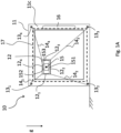
- FIG. 1A represented schematically therein is in front side view of a robotic arrangement 10 of the parallel-architecture type actuated by means of cables, of a known type, hence comprising a frame 11, having a parallelepipedal shape, as illustrated in the perspective view of Figure 1B , each side or edge of the parallelepiped being obtained, in the example, via a metal sectional element.
- the parallelepipedal frame 11 has six faces: a top face 11a, a bottom face 11b, and four side faces, namely the front face 11c, parallel to the working plane, illustrated in Figure 1A , the left-hand side face 11d, the rear side face 11e, and the right-hand side face 11f.
- actuators 13, in particular 13 1 , 13 2 , 13 3 , 13 4 which are, for example, motor-driven winders, or winches, which unwind and wind actuation cables 14, respectively 14 1 , 14 2 , 14 3 , 14 4 , the other end of which is fixed to a portion of a mobile support 12, respectively 12 1 , 12 2 , 12 3 , 12 4 , in the form of a rectangular mobile platform.
- This mobile support 12 comprises an end effector 15, in the example a laser source for etching surfaces.
- the laser source may have different powers and characteristics for carrying out other operations, or else there may be a video camera, or any other instrument suited to being moved by the robotic arrangement 10 described herein.
- the end effector 15 comprises, in the example, also a respective system for control of the laser source 151 and a Bluetooth communication module 152 for exchanging signals and for being in particular governed by a control module 16 located on the frame 11.
- Designated by 153 are power-supply batteries.
- the space of movement of the end effector 15, designated by 17 in Figure 1A is visible as a plane substantially parallel to the plane of the front face 11c of the frame 11 and defined by the strokes of the actuators 13, as well as being defined on the basis of its installation.
- the control module 16 and the actuators 13 are coupled to a power-supply system (not illustrated in the figures).
- FIG. 1B Represented in Figure 1B is a cable robotic arrangement of the same type as the arrangement 10 of Figure 1A , and it may be appreciated how, in this case, the frame 11 is a parallelepiped, with six faces consisting of a top face 11a, a bottom face 11b, and four side faces, namely, a front side face 11c, parallel to the working plane, illustrated in Figure 1A , a left-hand side face 11d, a rear side face 11e, and a right-hand side face 11f.
- the terms used for the faces refer to the configuration illustrated in Figures 1A-1B , given that the frame 11 has a parallelepipedal shape, as illustrated in 1B, where g indicates the direction of the acceleration of gravity, which enables definition of the vertical direction, the horizontal direction, and the top and bottom sides.
- the perspective view moreover makes it possible to appreciate how in this case in actual fact the plane 17 of movement is a parallelepipedal movement space 17 inside the parallelepiped defined by the frame 11, with faces parallel thereto, and once again defined by the strokes of the actuators 13 relative to each face or edge of the frame 11, in this case, as well as being defined on the basis of the installation.
- the mobile support 12 is in the form of a horizontal mobile platform. It should be noted that in general the mobile platform does not need to be a plane support.
- a robotic arrangement of the type described in Figures 1A , 1B is suited to industrial applications that do not envisage contact of the end effector with the surrounding environment, i.e., where the only external action exerted on the platform is gravity, for instance, laser etching for the decoration of surfaces, restoration, welding, thermal treatments, and inspection by means of video cameras.
- it has a rectangular plane working space, having a shape and size that may vary according to the installation. It is possible to scale the robotic arrangement, vary orientation of the working plane, and possibly render it portable, in a nimble and economically advantageous way thanks to the architecture and the logic of cable robots, without the need to redesign the actuation system.
- the actuators 13 that determine variation of the effective length of the actuation cables are preferably of a rotary type, for example, as illustrated, comprising a drum 131 that turns about an axis of rotation 131a, on and off which the cable 14 is wound and unwound, the drum 131 being driven by a servo-controlled electric motor 132.
- a system of this kind is commonly referred to as servo-controlled winch.
- each winch controls the length of a cable 14, which is guided along a path thereof P-a-b, from the drum 131, the point of exit of the cable therefrom being designated by P, to a distal anchorage point b on the platform 12, by one (or more) transmission pulleys 21 that identify a point a of transmission of the cable 14, or proximal anchorage point, towards the platform 12.
- a single-layer drum is preferably chosen, with a cable-guiding system determined by a helical groove. Furthermore, to enable the point A of exit of the cable 14 to be defined, the drum is configured to translate on a guide system, in the direction of its axis, during rotation. This linear motion is obtained by transforming the rotary motion, thanks to a transmission system, for example via a trapezoidal screw or a ballscrew. Translation of the drum on the linear guides and its rotation about the screw, are synchronized by a single actuation. The pitch of the winch and the pitch of the screw have for this purpose to be the same , but for their manufacturing tolerances.
- the robotic arrangement must in general be preferably configured to get the actuation cable 14 to exit at a fixed point, P, in space, for example via the translation of the drum in an axial direction during rotation described above. Then, the robotic arrangement, in order to be able to position the actuator at any point, even one not constrained to the frame, for example an ground, may envisage cable transmissions, such as the pulley 21, as far as the anchorage points, in the positions envisaged by the configuration of the robotic arrangement.
- the pattern of motion of the end effector is that of a point in the plane; i.e., it has two translational degrees of freedom, and is also referred to as "2T".
- 2T two translational degrees of freedom
- the working space and the installation space would have a triangular shape, which cannot be adapted to the requirements of certain applications among the ones mentioned.
- the working space broadens, and can become a quadrilateral, and moreover the platform is more stable and easily controllable.
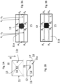
- FIG. 2A illustrated in Figure 2A is a front side view of a robotic arrangement 10 that operates in vertical configuration, as indicated by the acceleration of gravity g, whereas in Figure 2B the robotic arrangement 10 is illustrated in top plan view, where it is possible to identify the plane of movement 17 parallel to a working plane 18 and parallel to the front face 11c.
- each pair of cables in fact, comes under one and the same actuator, and is hence subject to one and the same variation of length.
- the lengths of the two cables remain the same.
- Illustrated in top plan view in Figure 3A is an eight-cable configuration, where designated by c 1 , c 2 , c 3 , c 4 are four of the actuation cables 14 visible from above through the top face 11a, the other four not being visible. Since the distance between the points of attachment of the cables (for example, the distances A 1 A 3 or B 1 B 3 ) that represent two sides of a parallelogram, where the other two sides are the cables (for example c 1 and c 3 ), does not vary in time, the cables are forced to lie in parallel planes.
- the distal anchorage points B 1 , B 2 , B 3 , B 4 or distal points B i are hence located on the edges of the platform 12, whereas the corresponding proximal anchorage points A 1 , A 2 , A 3 , A 4 or anchorage points Ai are arranged on two opposite sides of the face of the frame 11 parallel to the plane of movement 17, in the example the top face 11a, in positions determined by the parallelism of the cables 14, i.e., as has been said, equidistant. Even though this solution constrains the platform 12 to moving in a plane, it does not guarantee that both of the cables belonging to a parallelogram, controlled by one and the same motor, will be in tension.
- DE 10 2010 015530 discloses a planar cabledriven parallel robot whose actuation cables form loops, and whose distal transmission groups comprise articulated pulleys comprising a first pulley rotation axis parallel to the movement plane and a second rotation axis, about which said first rotation axis rotates, perpendicular to the movement plane.
- the object of the embodiments described herein is to improve the apparatuses and processes according to the prior art as discussed previously.
- the solution described herein relates to a parallel-architecture robotic arrangement, comprising a frame and an end effector mounted on a mobile support, in particular a mobile platform,
- said sensor assembly comprises a load cell configured to measure a load acting on the actuation cable that passes over a pulley of the proximal transmission assembly.
- said sensor assembly is configured in such a way that said acting load is set in a direction normal to the axis of the load cell.
- said proximal assembly comprises two articulated pulleys, the exit points of which represent the proximal anchorage points of the actuation cable arranged in a loop, and two fixed pulleys associated in a fixed way to the frame, which are set on the path of the actuation cable between the respective actuator and the respective articulated pulley.
- said distal assembly comprises respective articulated pulleys, the exit points of which represent the distal anchorage points of the actuation cable arranged in a loop, one of said two articulated pulleys transmitting said actuation cable to the other.
- said actuators are associated to the frame, in particular in the proximity of the respective proximal assembly.
- each actuation-cable loop is just one actuator; in particular, the ends of the actuation cable are associated to the drum of a servo-controlled winch.
- the two proximal anchorage points are associated to a respective portion of the frame, and two distal anchorage points are associated to a respective portion of the support in an equidistant way.
- the set of proximal anchorage points associated to a respective portion of the frame identifies a parallelepiped of the frame
- the set of distal anchorage points associated to a respective portion of the support identifies a respective parallelepiped of the support comprised in the parallelepiped of the frame.
- the cable-guide system for example the transmission pulley
- the actuation system is independent of the actuation system, in so far as the two parts may be combined together, without particular restrictive conditions.
- the solution described herein substantially envisages that, in the context of a cable robotic arrangement of a redundant type, with vertical orientation, which uses loop cable paths, as illustrated in Figure 3 , the guide system will comprise articulated pulleys, configured to rotate the plane of the pulley about an axis perpendicular to the plane of movement of the support of the end effector, and will moreover comprise a force sensor for detecting the force applied to the cables of each loop.
- FIG 5 illustrates a robotic arrangement 10' according to the invention, in schematic front side view.
- the robotic arrangement 10' is illustrated in schematic top plan view.
- the robotic arrangement 10' has a configuration like the one of Figure 3A .
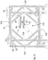
- the robotic arrangement 11 has the substantially parallelepipedal frame 11, as may be seen more clearly in the perspective view of Figure 11 , which comprises within it the support 12, while four actuation cables 14 are provided, which couple the facing sides of the frame 11 and of the support 12, each forming a respective loop or parallelogram l 1 , l 2 , l 3 , l 4 .
- the frame 11 does not need to have a parallepipedal shape, but must be such as to make possible an arrangement of proximal points of a parallepipedal shape.
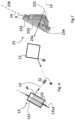
- articulated or mobile pulleys 23 which are described in greater detail in what follows with reference to Figure 7 .
- These articulated or mobile pulleys 23 reduce considerably the wear of the cable for deflections having components in the direction of the articulated joint, even though they introduce a complexity in the kinematic model.
- Figure 7 which represents an articulated pulley 23 in schematic perspective view, the aforesaid articulated pulley 23 comprises a rotating disk 231 of its own that turns about an axis of rotation 23a.
- the articulated pulley 23 further comprises a hollow tubular support 232, having a respective main longitudinal axis that identifies a second axis of rotation 23b, and is associated to cantilever supports 233 for carrying the pins of rotation of the rotating disk 231.
- the second axis of rotation 23b is perpendicular to the axis of the pulley proper, i.e., the axis 23a, and coaxial with the direction of the incoming cable 14, which is introduced through the hollow support 232.
- the articulated pulley 23 can turn through an angle of attachment ⁇ about the second axis of rotation 23b, also the first axis of rotation 23a of the pulley turning through the same angle, and hence also the direction of the cable 14 that exits towards the support 12 turning through the same angle.
- This system enables orientation of the cable in a wide range of directions.
- the second axis of rotation 23b is perpendicular to the plane of movement 17, which substantially coincides with the side of the frame to which the pulley 23 is fixed, so that the plane of the rotating disk 231 of the articulated pulley 23 turns according to an axis perpendicular to the plane of movement 17 through the angle of attachment ⁇ .
- the robotic arrangement 10' in the proximal anchorage points A i on the frame 11 comprises respective articulated pulleys 23 that receive the cable 14 from actuators 13.
- the proximal anchorage points in this case are located along the side of the frame 11 at the same distance as the points of Figure 3B ; however, they are shifted by a distance equal to the radius r of the articulated pulley 23 in the direction of the cable 14.
- proximal anchorage points A i and distal anchorage points B i in the solution described here are defined as virtual points identified by the intersection between the second axes of rotation of the mobile pulleys, the proximal ones 23 and the distal ones 24 respectively, and the planes passing through the cables li and parallel to the working plane 17.
- the (virtual) proximal points Ai and distal points B i are identified by the intersection of the axes 23bi and 24bi with the aforesaid plane passing through an i-th cable li parallel to the aforesaid vertical working plane.
- the actuators 13 are not visible either in Figure 5 or in Figure 6 , but are in general located, for example, on the outer part of the frame 11, as illustrated for example in Figure 11 , described in what follows.
- associated to each loop li of the actuation cable 14 is just one actuator 13, the ends of the actuation cable 14 being associated to the drum 131 of a servo-controlled winch, as illustrated in Figure 4 .
- This embodiment is preferable, but in variant embodiments there may be two actuators for each end of the actuation cable 14 that forms the loop li.
- articulated pulleys 24 are located at the points of attachment B i of the cables on the platform 12; i.e., the second axis of rotation is parallel to the side of the platform 12, and also the plane of the rotating disk of the articulated pulley 24 turns according to an axis perpendicular to the plane of movement 17 through the angle of attachment ⁇ .
- These articulated pulleys 24 hence make it possible to maintain the standard kinematic model defined, leaving to the cable 14 the possibility of deflecting freely, with a wide range of angles ⁇ of attachment and so that the cable can transmit force to another element of the robotic arrangement 10'.
- the cableplatform connection must be able to withstand forces acting in different directions.
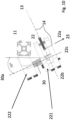
- the robotic arrangement 10' as illustrated in Figure 8 , comprises a proximal assembly 25, represented in perspective view; i.e., the assembly for transmission of the cable 14 from the actuator 13, at a pair of proximal points of a loop, in the example A 1 and A 2 of the loop l 1 , gathers the cable 14 leaving the drum 131 of the actuator 13 with a fixed pulley 22, mounted with axis normal to the plane in which the cables 14 lie, and transmits it immediately to the mobile pulley 23, the articulated axis 23b of which lies perpendicular to the plane of movement 17.
- the proximal point Ai of the cable 14, corresponding to the exit point on the articulated pulley 23, is defined by the position of the articulated axis or second axis of rotation 23b, fixed with respect to the frame 11.
- the cable-guide system is hence integrated with the sensors necessary for control of the machine.
- the most common strategies of control of cable robots require measurements to be carried out on the system during its operation in order to improve the performance of the robot.
- the solution described comprises a force sensor, specifically a load cell, to determine the tension of the cable and hence the forces applied to the platform 12 and to the end effector 15.
- a sensor assembly 30 that is associated to the fixed pulleys 22 for measuring the tension of the cables actuated by the actuator 13.
- the fixed pulley 22 comprises, in addition to a body 221 in which the rotating disk turns, a second body 222 associated to the frame 11, between which bodies the sensor 30, i.e., the load cell, is set.
- the load cell used for measuring the tension of the cable 14 is preferably a strain-gauge load cell.
- the overall support formed by the bodies 221 and 222 between which the sensor 30 is set has an axis 22c, which is perpendicular to the direction of loading and forms a certain angle, e.g., 30°, with the plane of the frame 11.
- the load cell is directly connected to a pulley present in the system, without any need for additional devices.
- the fixed pulley and the mobile pulley have two different purposes, respectively, measurement of the average tension in the cable branch, via a load cell connected thereto, and orientation of the cable within the working space.
- the cable hence departs from the drum 131 always from the same position, and is sent to the sensorized pulley 22.
- This solution is particularly economical in so far as it enables use of a minimal number of components.
- the sensor 30, provided with two pairs of threaded holes for constraint to the frame 11 on one side, through the body 222, and the anchorage of the load on the other side (body 221), is positioned within the system of fixed pulleys 22, which gathers the cable leaving the drum 13.
- the sensor assembly 30 is thus configured in such a way that the acting load is oriented in a direction normal to the axis of the load cell, i.e., the axis 22c.
- the robotic arrangement 10' comprises a control system, for example a microprocessor control system, which is coupled in communication with the servo-controlled actuators and receives the measurements of tension of the cables from the sensor 30, and which preferably implements a standard control model, which follows the hypotheses of a multibody system with rigid members: the cables are considered as "distances" between points in space, the proximal point on the frame and the distal point on the platform. In this way, all the problems introduced by the non-linear behaviour of the cables are neglected and they are simply modelled as prismatic joints.
- the apparatus according to the invention advantageously makes it possible to apply the standard model for control once also a the value of average tension of the entire segment of actuation cable of a loop to be entered in the control model is known.
Landscapes
- Engineering & Computer Science (AREA)
- Robotics (AREA)
- Mechanical Engineering (AREA)
- Human Computer Interaction (AREA)
- Manipulator (AREA)
Claims (9)
- Roboteranordnung mit paralleler Architektur, umfassend einen Rahmen (11) und einen Endeffektor (15), der auf einem mobilen Träger (12), insbesondere einer mobilen Plattform, montiert ist,wobei der mobile Träger (12) mit dem Rahmen (11) über eine Vielzahl von Betätigungskabeln (14), insbesondere vier Betätigungskabel, so verbunden ist, dass dieser sich gemäß zwei Freiheitsgraden in einem ebenen rechteckigen Bewegungsraum (17) bewegt,wobei die Roboteranordnung (10) eine Vielzahl von Aktuatoren (13) zum Bewegen jeweiliger Betätigungskabel (14) umfasst, wobei die Anzahl der Aktuatoren (13) größer als die Freiheitsgrade des Endeffektors (15) ist,wobei jedes Betätigungskabel (14) einen entsprechenden Abschnitt des Rahmens (11) und einen entsprechenden Abschnitt des mobilen Trägers (12) gemäß einem Schleifenweg (Ii) zwischen zumindest zwei proximalen dem Abschnitt des Rahmens (11) zugeordneten Ankerpunkten (Al) und zwei distalen dem jeweiligen Abschnitt des Trägers (12) zugeordneten Ankerpunkten (Bi) koppelt,wobei die Roboteranordnung (10) für jede Schleife (Ii) eine proximale Übertragungsbaugruppe (25) umfasst, die an dem Rahmen (11) stromabwärts jedes Aktuators (13) in Bezug auf den Weg des Kabels (14) positioniert ist, und eine distale Übertragungsbaugruppe (26) umfasst, die auf dem mobilen Träger (12) des Endeffektors (15) positioniert ist,wobei jede zwischen der proximalen Übertragungsbaugruppe (25) und der distalen Übertragungsbaugruppe (26) an den jeweiligen Ankerpunkten (Ai, Bi) Gelenkrollen (23, 24) umfassen, die jeweils eine erste Drehachse (23a, 24a) der jeweiligen Rolle aufweisen, insbesondere einer rotierenden Scheibe davon (231), die parallel zu dem ebenen rechteckigen Bewegungsraum (17) ist, und eine zweite Drehachse (23b) aufweisen, um welche die erste Drehachse (23a) sich dreht, die senkrecht zu dem ebenen rechteckigen Bewegungsraum (17) ist, wobei der Austrittspunkt des Betätigungskabels (14) an jeder Rolle (23, 24) den jeweiligen Ankerpunkt (Ai, Bi) kennzeichnet,wobei die proximale Übertragungsbaugruppe (25) einem Sensor (30) zugeordnet ist, der ausgebildet ist, die Spannung des jeweiligen Betätigungskabels (14) zu messen.
- Anordnung nach Anspruch 1, dadurch gekennzeichnet, dass die Sensoranordnung (30) eine Lastzelle umfasst, die ausgebildet ist, eine Last zu messen, die auf das Betätigungskabel (14) wirkt, das über eine weitere Rolle (22) der proximalen Übertragungsbaugruppe (25) läuft.
- Anordnung nach Anspruch 2, dadurch gekennzeichnet, dass die Sensoranordnung (30) so ausgebildet ist, dass die wirkende Last in einer Richtung normal zu der Lastachse (22c) der Lastzelle (30) eingestellt ist.
- Anordnung nach Anspruch 1, dadurch gekennzeichnet, dass die proximale Baugruppe (25) zwei Gelenkrollen (24) umfasst, deren Austrittspunkte die proximalen Ankerpunkte des in einer Schleife angeordneten Betätigungskabels (14) darstellen, und zwei feste Rollen (22) umfasst, die fest dem Rahmen (11) zugeordnet sind und auf dem Weg des Betätigungskabels (14) zwischen dem jeweiligen Aktuator (13) und der jeweiligen Gelenkrolle (24) angeordnet sind.
- Anordnung nach Anspruch 4, dadurch gekennzeichnet, dass die distale Baugruppe (26) jeweilige Gelenkrollen (24) umfasst, deren Ausgangspunkte die distalen Ankerpunkte (Bi) des in einer Schleife angeordneten Betätigungskabels (14) darstellen, wobei eine der beiden Gelenkrollen das Betätigungskabel (14) auf die andere überträgt.
- Anordnung nach einem der vorhergehenden Ansprüche, dadurch gekennzeichnet, dass die Aktuatoren (13) dem Rahmen (11) zugeordnet sind, insbesondere in der Nähe der jeweiligen proximalen Baugruppe (25).
- Anordnung nach einem der vorhergehenden Ansprüche, dadurch gekennzeichnet, dass nur ein Aktuator (13) jeder Betätigungskabelschleife zugeordnet ist, wobei insbesondere die Enden des Betätigungskabels (14) der Trommel (131) einer servogesteuerten Winde zugeordnet sind.
- Anordnung nach einem der vorhergehenden Ansprüche, dadurch gekennzeichnet, dass die beiden proximalen Ankerpunkte einem jeweiligen Abschnitt des Rahmens (11) zugeordnet sind, und dass die beiden distalen Ankerpunkte (Bi) einem jeweiligen Abschnitt des Trägers (12) in gleichem Abstand zugeordnet sind.
- Anordnung nach einem der vorhergehenden Ansprüche, dadurch gekennzeichnet, dass die Menge der proximalen Ankerpunkte (Ai), die einem jeweiligen Abschnitt des Rahmens (11) zugeordnet sind, ein Parallelepiped des Rahmens kennzeichnet, und dass die Menge der distalen Ankerpunkte (Bi), die einem jeweiligen Abschnitt des Trägers (12) zugeordnet sind, ein entsprechendes Parallelepiped des Trägers kennzeichnet, das in dem Parallelepiped des Rahmens (11) umfasst ist.
Applications Claiming Priority (2)
| Application Number | Priority Date | Filing Date | Title |
|---|---|---|---|
| IT102020000000478A IT202000000478A1 (it) | 2020-01-13 | 2020-01-13 | Dispositivo robotico ad architettura parallela |
| PCT/IB2021/050185 WO2021144685A1 (en) | 2020-01-13 | 2021-01-12 | Robotic arrangement with parallel architecture |
Publications (3)
| Publication Number | Publication Date |
|---|---|
| EP4090499A1 EP4090499A1 (de) | 2022-11-23 |
| EP4090499B1 true EP4090499B1 (de) | 2023-12-20 |
| EP4090499C0 EP4090499C0 (de) | 2023-12-20 |
Family
ID=70295732
Family Applications (1)
| Application Number | Title | Priority Date | Filing Date |
|---|---|---|---|
| EP21703978.3A Active EP4090499B1 (de) | 2020-01-13 | 2021-01-12 | Roboteranordnung mit paralleler architektur |
Country Status (3)
| Country | Link |
|---|---|
| EP (1) | EP4090499B1 (de) |
| IT (1) | IT202000000478A1 (de) |
| WO (1) | WO2021144685A1 (de) |
Families Citing this family (3)
| Publication number | Priority date | Publication date | Assignee | Title |
|---|---|---|---|---|
| EP4155033A1 (de) * | 2021-09-28 | 2023-03-29 | ETH Zurich | Roboter, robotisches system, und verfahren zum manipulieren von objekten mit diesem robotischen system |
| CN114393565B (zh) * | 2022-01-20 | 2023-09-05 | 清华大学 | 绳索驱动的高精度两自由度并联机器人 |
| CN114434423B (zh) * | 2022-01-20 | 2023-09-05 | 清华大学 | 平行索驱动的平面两自由度并联机器人 |
Family Cites Families (2)
| Publication number | Priority date | Publication date | Assignee | Title |
|---|---|---|---|---|
| DE102010015530B4 (de) * | 2010-04-20 | 2012-09-06 | Sandra Wahle | Lagersystem, insbesondere Regallager |
| US11926051B2 (en) * | 2018-06-14 | 2024-03-12 | Cameron Reed McROBERTS | Apparatus and method for cable-driven robotics |
-
2020
- 2020-01-13 IT IT102020000000478A patent/IT202000000478A1/it unknown
-
2021
- 2021-01-12 EP EP21703978.3A patent/EP4090499B1/de active Active
- 2021-01-12 WO PCT/IB2021/050185 patent/WO2021144685A1/en not_active Ceased
Also Published As
| Publication number | Publication date |
|---|---|
| WO2021144685A1 (en) | 2021-07-22 |
| EP4090499C0 (de) | 2023-12-20 |
| IT202000000478A1 (it) | 2021-07-13 |
| EP4090499A1 (de) | 2022-11-23 |
Similar Documents
| Publication | Publication Date | Title |
|---|---|---|
| EP4090499B1 (de) | Roboteranordnung mit paralleler architektur | |
| US5313854A (en) | Light weight robot mechanism | |
| US6840127B2 (en) | Tendon link mechanism with six degrees of freedom | |
| US10189158B2 (en) | Robot manipulator with modular torque controlled link | |
| US4606696A (en) | Mechanism to determine position and orientation in space | |
| Izard et al. | A reconfigurable robot for cable-driven parallel robotic research and industrial scenario proofing | |
| Horigome et al. | Development of a coupled tendon-driven 3D multi-joint manipulator | |
| EP4069993B1 (de) | Vorrichtung mit einem antriebssystem und einem mobilen roboter | |
| US20190009417A1 (en) | Driving mechanism, robot arm, and robot system | |
| US11491645B2 (en) | Scissor linkage design and method of operation | |
| US7477965B2 (en) | Twisting wire actuator | |
| Choi et al. | Design and evaluation of a cable-actuated palletizing robot with geared rolling joints | |
| CN114434423B (zh) | 平行索驱动的平面两自由度并联机器人 | |
| US10035265B2 (en) | Manipulator | |
| JP3777783B2 (ja) | 水平アームを有するロボット | |
| US20250058482A1 (en) | Joint apparatus for robot | |
| Luo et al. | D3-ARM: High-Dynamic, Dexterous and Fully Decoupled Cable-driven Robotic Arm | |
| Komendera et al. | Control system design implementation and preliminary demonstration for a tendon actuated lightweight in-space MANipulator (TALISMAN) | |
| Suh et al. | Design and verification of parallelogram mechanism with geared unit rolling joints for reliable wiring | |
| US20230182327A1 (en) | Holding mechanism, robot device | |
| Sciarra et al. | Design and kinetostatic modeling of a cable-driven Schönflies-motion generator | |
| JP4124232B2 (ja) | 水平アームを有するロボット | |
| KR101252108B1 (ko) | 모션 비간섭 케이블 구동장치 | |
| Zhang | Kinematically controllable cable robots with reconfigurable end-effectors | |
| KR20190129323A (ko) | 로봇 암 어셈블리 |
Legal Events
| Date | Code | Title | Description |
|---|---|---|---|
| STAA | Information on the status of an ep patent application or granted ep patent |
Free format text: STATUS: UNKNOWN |
|
| STAA | Information on the status of an ep patent application or granted ep patent |
Free format text: STATUS: THE INTERNATIONAL PUBLICATION HAS BEEN MADE |
|
| PUAI | Public reference made under article 153(3) epc to a published international application that has entered the european phase |
Free format text: ORIGINAL CODE: 0009012 |
|
| STAA | Information on the status of an ep patent application or granted ep patent |
Free format text: STATUS: REQUEST FOR EXAMINATION WAS MADE |
|
| 17P | Request for examination filed |
Effective date: 20220713 |
|
| AK | Designated contracting states |
Kind code of ref document: A1 Designated state(s): AL AT BE BG CH CY CZ DE DK EE ES FI FR GB GR HR HU IE IS IT LI LT LU LV MC MK MT NL NO PL PT RO RS SE SI SK SM TR |
|
| DAV | Request for validation of the european patent (deleted) | ||
| DAX | Request for extension of the european patent (deleted) | ||
| GRAP | Despatch of communication of intention to grant a patent |
Free format text: ORIGINAL CODE: EPIDOSNIGR1 |
|
| STAA | Information on the status of an ep patent application or granted ep patent |
Free format text: STATUS: GRANT OF PATENT IS INTENDED |
|
| INTG | Intention to grant announced |
Effective date: 20230808 |
|
| GRAS | Grant fee paid |
Free format text: ORIGINAL CODE: EPIDOSNIGR3 |
|
| GRAA | (expected) grant |
Free format text: ORIGINAL CODE: 0009210 |
|
| STAA | Information on the status of an ep patent application or granted ep patent |
Free format text: STATUS: THE PATENT HAS BEEN GRANTED |
|
| AK | Designated contracting states |
Kind code of ref document: B1 Designated state(s): AL AT BE BG CH CY CZ DE DK EE ES FI FR GB GR HR HU IE IS IT LI LT LU LV MC MK MT NL NO PL PT RO RS SE SI SK SM TR |
|
| REG | Reference to a national code |
Ref country code: GB Ref legal event code: FG4D |
|
| REG | Reference to a national code |
Ref country code: CH Ref legal event code: EP |
|
| REG | Reference to a national code |
Ref country code: DE Ref legal event code: R096 Ref document number: 602021007886 Country of ref document: DE |
|
| REG | Reference to a national code |
Ref country code: IE Ref legal event code: FG4D |
|
| U01 | Request for unitary effect filed |
Effective date: 20240109 |
|
| U07 | Unitary effect registered |
Designated state(s): AT BE BG DE DK EE FI FR IT LT LU LV MT NL PT SE SI Effective date: 20240118 |
|
| U20 | Renewal fee for the european patent with unitary effect paid |
Year of fee payment: 4 Effective date: 20240115 |
|
| PG25 | Lapsed in a contracting state [announced via postgrant information from national office to epo] |
Ref country code: GR Free format text: LAPSE BECAUSE OF FAILURE TO SUBMIT A TRANSLATION OF THE DESCRIPTION OR TO PAY THE FEE WITHIN THE PRESCRIBED TIME-LIMIT Effective date: 20240321 |
|
| PG25 | Lapsed in a contracting state [announced via postgrant information from national office to epo] |
Ref country code: ES Free format text: LAPSE BECAUSE OF FAILURE TO SUBMIT A TRANSLATION OF THE DESCRIPTION OR TO PAY THE FEE WITHIN THE PRESCRIBED TIME-LIMIT Effective date: 20231220 |
|
| PG25 | Lapsed in a contracting state [announced via postgrant information from national office to epo] |
Ref country code: GR Free format text: LAPSE BECAUSE OF FAILURE TO SUBMIT A TRANSLATION OF THE DESCRIPTION OR TO PAY THE FEE WITHIN THE PRESCRIBED TIME-LIMIT Effective date: 20240321 Ref country code: ES Free format text: LAPSE BECAUSE OF FAILURE TO SUBMIT A TRANSLATION OF THE DESCRIPTION OR TO PAY THE FEE WITHIN THE PRESCRIBED TIME-LIMIT Effective date: 20231220 |
|
| PG25 | Lapsed in a contracting state [announced via postgrant information from national office to epo] |
Ref country code: RS Free format text: LAPSE BECAUSE OF FAILURE TO SUBMIT A TRANSLATION OF THE DESCRIPTION OR TO PAY THE FEE WITHIN THE PRESCRIBED TIME-LIMIT Effective date: 20231220 Ref country code: NO Free format text: LAPSE BECAUSE OF FAILURE TO SUBMIT A TRANSLATION OF THE DESCRIPTION OR TO PAY THE FEE WITHIN THE PRESCRIBED TIME-LIMIT Effective date: 20240320 Ref country code: HR Free format text: LAPSE BECAUSE OF FAILURE TO SUBMIT A TRANSLATION OF THE DESCRIPTION OR TO PAY THE FEE WITHIN THE PRESCRIBED TIME-LIMIT Effective date: 20231220 |
|
| PG25 | Lapsed in a contracting state [announced via postgrant information from national office to epo] |
Ref country code: IS Free format text: LAPSE BECAUSE OF FAILURE TO SUBMIT A TRANSLATION OF THE DESCRIPTION OR TO PAY THE FEE WITHIN THE PRESCRIBED TIME-LIMIT Effective date: 20240420 |
|
| PG25 | Lapsed in a contracting state [announced via postgrant information from national office to epo] |
Ref country code: CZ Free format text: LAPSE BECAUSE OF FAILURE TO SUBMIT A TRANSLATION OF THE DESCRIPTION OR TO PAY THE FEE WITHIN THE PRESCRIBED TIME-LIMIT Effective date: 20231220 |
|
| PG25 | Lapsed in a contracting state [announced via postgrant information from national office to epo] |
Ref country code: SK Free format text: LAPSE BECAUSE OF FAILURE TO SUBMIT A TRANSLATION OF THE DESCRIPTION OR TO PAY THE FEE WITHIN THE PRESCRIBED TIME-LIMIT Effective date: 20231220 |
|
| PG25 | Lapsed in a contracting state [announced via postgrant information from national office to epo] |
Ref country code: SM Free format text: LAPSE BECAUSE OF FAILURE TO SUBMIT A TRANSLATION OF THE DESCRIPTION OR TO PAY THE FEE WITHIN THE PRESCRIBED TIME-LIMIT Effective date: 20231220 Ref country code: SK Free format text: LAPSE BECAUSE OF FAILURE TO SUBMIT A TRANSLATION OF THE DESCRIPTION OR TO PAY THE FEE WITHIN THE PRESCRIBED TIME-LIMIT Effective date: 20231220 Ref country code: RO Free format text: LAPSE BECAUSE OF FAILURE TO SUBMIT A TRANSLATION OF THE DESCRIPTION OR TO PAY THE FEE WITHIN THE PRESCRIBED TIME-LIMIT Effective date: 20231220 Ref country code: IS Free format text: LAPSE BECAUSE OF FAILURE TO SUBMIT A TRANSLATION OF THE DESCRIPTION OR TO PAY THE FEE WITHIN THE PRESCRIBED TIME-LIMIT Effective date: 20240420 Ref country code: CZ Free format text: LAPSE BECAUSE OF FAILURE TO SUBMIT A TRANSLATION OF THE DESCRIPTION OR TO PAY THE FEE WITHIN THE PRESCRIBED TIME-LIMIT Effective date: 20231220 |
|
| PG25 | Lapsed in a contracting state [announced via postgrant information from national office to epo] |
Ref country code: PL Free format text: LAPSE BECAUSE OF FAILURE TO SUBMIT A TRANSLATION OF THE DESCRIPTION OR TO PAY THE FEE WITHIN THE PRESCRIBED TIME-LIMIT Effective date: 20231220 |
|
| PG25 | Lapsed in a contracting state [announced via postgrant information from national office to epo] |
Ref country code: PL Free format text: LAPSE BECAUSE OF FAILURE TO SUBMIT A TRANSLATION OF THE DESCRIPTION OR TO PAY THE FEE WITHIN THE PRESCRIBED TIME-LIMIT Effective date: 20231220 |
|
| REG | Reference to a national code |
Ref country code: CH Ref legal event code: PL |
|
| U1N | Appointed representative for the unitary patent procedure changed after the registration of the unitary effect |
Representative=s name: BUZZI, NOTARO & ANTONIELLI D'OULX S.P.A.; IT |
|
| REG | Reference to a national code |
Ref country code: DE Ref legal event code: R097 Ref document number: 602021007886 Country of ref document: DE |
|
| PG25 | Lapsed in a contracting state [announced via postgrant information from national office to epo] |
Ref country code: MC Free format text: LAPSE BECAUSE OF FAILURE TO SUBMIT A TRANSLATION OF THE DESCRIPTION OR TO PAY THE FEE WITHIN THE PRESCRIBED TIME-LIMIT Effective date: 20231220 |
|
| PG25 | Lapsed in a contracting state [announced via postgrant information from national office to epo] |
Ref country code: CH Free format text: LAPSE BECAUSE OF NON-PAYMENT OF DUE FEES Effective date: 20240131 |
|
| PLBE | No opposition filed within time limit |
Free format text: ORIGINAL CODE: 0009261 |
|
| STAA | Information on the status of an ep patent application or granted ep patent |
Free format text: STATUS: NO OPPOSITION FILED WITHIN TIME LIMIT |
|
| PG25 | Lapsed in a contracting state [announced via postgrant information from national office to epo] |
Ref country code: CH Free format text: LAPSE BECAUSE OF NON-PAYMENT OF DUE FEES Effective date: 20240131 |
|
| 26N | No opposition filed |
Effective date: 20240923 |
|
| PG25 | Lapsed in a contracting state [announced via postgrant information from national office to epo] |
Ref country code: IE Free format text: LAPSE BECAUSE OF NON-PAYMENT OF DUE FEES Effective date: 20240112 |
|
| PG25 | Lapsed in a contracting state [announced via postgrant information from national office to epo] |
Ref country code: IE Free format text: LAPSE BECAUSE OF NON-PAYMENT OF DUE FEES Effective date: 20240112 |
|
| PG25 | Lapsed in a contracting state [announced via postgrant information from national office to epo] |
Ref country code: CY Free format text: LAPSE BECAUSE OF FAILURE TO SUBMIT A TRANSLATION OF THE DESCRIPTION OR TO PAY THE FEE WITHIN THE PRESCRIBED TIME-LIMIT; INVALID AB INITIO Effective date: 20210112 |
|
| PG25 | Lapsed in a contracting state [announced via postgrant information from national office to epo] |
Ref country code: HU Free format text: LAPSE BECAUSE OF FAILURE TO SUBMIT A TRANSLATION OF THE DESCRIPTION OR TO PAY THE FEE WITHIN THE PRESCRIBED TIME-LIMIT; INVALID AB INITIO Effective date: 20210112 |
|
| U90 | Renewal fees not paid: noting of loss of rights |
Free format text: RENEWAL FEE NOT PAID FOR YEAR 05 Effective date: 20250814 |
|
| GBPC | Gb: european patent ceased through non-payment of renewal fee |
Effective date: 20250112 |
|
| PG25 | Lapsed in a contracting state [announced via postgrant information from national office to epo] |
Ref country code: GB Free format text: LAPSE BECAUSE OF NON-PAYMENT OF DUE FEES Effective date: 20250112 |
|
| U93 | Unitary patent lapsed |
Free format text: RENEWAL FEE NOT PAID Effective date: 20250131 |