EP4155033A1 - Roboter, robotisches system, und verfahren zum manipulieren von objekten mit diesem robotischen system - Google Patents
Roboter, robotisches system, und verfahren zum manipulieren von objekten mit diesem robotischen system Download PDFInfo
- Publication number
- EP4155033A1 EP4155033A1 EP21199312.6A EP21199312A EP4155033A1 EP 4155033 A1 EP4155033 A1 EP 4155033A1 EP 21199312 A EP21199312 A EP 21199312A EP 4155033 A1 EP4155033 A1 EP 4155033A1
- Authority
- EP
- European Patent Office
- Prior art keywords
- pulley
- robot
- actuator
- cable
- coaxial
- Prior art date
- Legal status (The legal status is an assumption and is not a legal conclusion. Google has not performed a legal analysis and makes no representation as to the accuracy of the status listed.)
- Withdrawn
Links
- 238000000034 method Methods 0.000 title claims abstract description 11
- 230000005540 biological transmission Effects 0.000 claims abstract description 41
- 230000033001 locomotion Effects 0.000 claims abstract description 28
- 238000012545 processing Methods 0.000 claims abstract description 7
- 230000007246 mechanism Effects 0.000 claims description 49
- 238000004804 winding Methods 0.000 claims description 14
- 230000004913 activation Effects 0.000 description 27
- 230000008878 coupling Effects 0.000 description 24
- 238000010168 coupling process Methods 0.000 description 24
- 238000005859 coupling reaction Methods 0.000 description 24
- 230000008901 benefit Effects 0.000 description 13
- 241000196324 Embryophyta Species 0.000 description 5
- 238000010586 diagram Methods 0.000 description 5
- 239000011159 matrix material Substances 0.000 description 4
- 238000013461 design Methods 0.000 description 3
- 238000005265 energy consumption Methods 0.000 description 3
- 238000012546 transfer Methods 0.000 description 3
- 230000015572 biosynthetic process Effects 0.000 description 2
- 238000010276 construction Methods 0.000 description 2
- 230000001419 dependent effect Effects 0.000 description 2
- 238000013138 pruning Methods 0.000 description 2
- 240000008042 Zea mays Species 0.000 description 1
- 235000005824 Zea mays ssp. parviglumis Nutrition 0.000 description 1
- 235000002017 Zea mays subsp mays Nutrition 0.000 description 1
- 230000008859 change Effects 0.000 description 1
- 238000006243 chemical reaction Methods 0.000 description 1
- 238000001816 cooling Methods 0.000 description 1
- 235000005822 corn Nutrition 0.000 description 1
- 230000000694 effects Effects 0.000 description 1
- 238000007667 floating Methods 0.000 description 1
- 230000017525 heat dissipation Effects 0.000 description 1
- 238000010348 incorporation Methods 0.000 description 1
- 238000000465 moulding Methods 0.000 description 1
- 230000037361 pathway Effects 0.000 description 1
- 230000008707 rearrangement Effects 0.000 description 1
- 239000000126 substance Substances 0.000 description 1
- 238000003466 welding Methods 0.000 description 1
Images


Classifications
-
- F—MECHANICAL ENGINEERING; LIGHTING; HEATING; WEAPONS; BLASTING
- F16—ENGINEERING ELEMENTS AND UNITS; GENERAL MEASURES FOR PRODUCING AND MAINTAINING EFFECTIVE FUNCTIONING OF MACHINES OR INSTALLATIONS; THERMAL INSULATION IN GENERAL
- F16H—GEARING
- F16H19/00—Gearings comprising essentially only toothed gears or friction members and not capable of conveying indefinitely-continuing rotary motion
- F16H19/02—Gearings comprising essentially only toothed gears or friction members and not capable of conveying indefinitely-continuing rotary motion for interconverting rotary or oscillating motion and reciprocating motion
- F16H19/06—Gearings comprising essentially only toothed gears or friction members and not capable of conveying indefinitely-continuing rotary motion for interconverting rotary or oscillating motion and reciprocating motion comprising flexible members, e.g. an endless flexible member
-
- B—PERFORMING OPERATIONS; TRANSPORTING
- B25—HAND TOOLS; PORTABLE POWER-DRIVEN TOOLS; MANIPULATORS
- B25J—MANIPULATORS; CHAMBERS PROVIDED WITH MANIPULATION DEVICES
- B25J9/00—Programme-controlled manipulators
- B25J9/003—Programme-controlled manipulators having parallel kinematics
- B25J9/0078—Programme-controlled manipulators having parallel kinematics actuated by cables
-
- F—MECHANICAL ENGINEERING; LIGHTING; HEATING; WEAPONS; BLASTING
- F16—ENGINEERING ELEMENTS AND UNITS; GENERAL MEASURES FOR PRODUCING AND MAINTAINING EFFECTIVE FUNCTIONING OF MACHINES OR INSTALLATIONS; THERMAL INSULATION IN GENERAL
- F16H—GEARING
- F16H48/00—Differential gearings
- F16H48/06—Differential gearings with gears having orbital motion
- F16H48/08—Differential gearings with gears having orbital motion comprising bevel gears
-
- F—MECHANICAL ENGINEERING; LIGHTING; HEATING; WEAPONS; BLASTING
- F16—ENGINEERING ELEMENTS AND UNITS; GENERAL MEASURES FOR PRODUCING AND MAINTAINING EFFECTIVE FUNCTIONING OF MACHINES OR INSTALLATIONS; THERMAL INSULATION IN GENERAL
- F16M—FRAMES, CASINGS OR BEDS OF ENGINES, MACHINES OR APPARATUS, NOT SPECIFIC TO ENGINES, MACHINES OR APPARATUS PROVIDED FOR ELSEWHERE; STANDS; SUPPORTS
- F16M11/00—Stands or trestles as supports for apparatus or articles placed thereon ; Stands for scientific apparatus such as gravitational force meters
- F16M11/02—Heads
- F16M11/04—Means for attachment of apparatus; Means allowing adjustment of the apparatus relatively to the stand
- F16M11/043—Allowing translations
-
- F—MECHANICAL ENGINEERING; LIGHTING; HEATING; WEAPONS; BLASTING
- F16—ENGINEERING ELEMENTS AND UNITS; GENERAL MEASURES FOR PRODUCING AND MAINTAINING EFFECTIVE FUNCTIONING OF MACHINES OR INSTALLATIONS; THERMAL INSULATION IN GENERAL
- F16M—FRAMES, CASINGS OR BEDS OF ENGINES, MACHINES OR APPARATUS, NOT SPECIFIC TO ENGINES, MACHINES OR APPARATUS PROVIDED FOR ELSEWHERE; STANDS; SUPPORTS
- F16M11/00—Stands or trestles as supports for apparatus or articles placed thereon ; Stands for scientific apparatus such as gravitational force meters
- F16M11/02—Heads
- F16M11/04—Means for attachment of apparatus; Means allowing adjustment of the apparatus relatively to the stand
- F16M11/06—Means for attachment of apparatus; Means allowing adjustment of the apparatus relatively to the stand allowing pivoting
-
- F—MECHANICAL ENGINEERING; LIGHTING; HEATING; WEAPONS; BLASTING
- F16—ENGINEERING ELEMENTS AND UNITS; GENERAL MEASURES FOR PRODUCING AND MAINTAINING EFFECTIVE FUNCTIONING OF MACHINES OR INSTALLATIONS; THERMAL INSULATION IN GENERAL
- F16M—FRAMES, CASINGS OR BEDS OF ENGINES, MACHINES OR APPARATUS, NOT SPECIFIC TO ENGINES, MACHINES OR APPARATUS PROVIDED FOR ELSEWHERE; STANDS; SUPPORTS
- F16M11/00—Stands or trestles as supports for apparatus or articles placed thereon ; Stands for scientific apparatus such as gravitational force meters
- F16M11/02—Heads
- F16M11/18—Heads with mechanism for moving the apparatus relatively to the stand
-
- F—MECHANICAL ENGINEERING; LIGHTING; HEATING; WEAPONS; BLASTING
- F16—ENGINEERING ELEMENTS AND UNITS; GENERAL MEASURES FOR PRODUCING AND MAINTAINING EFFECTIVE FUNCTIONING OF MACHINES OR INSTALLATIONS; THERMAL INSULATION IN GENERAL
- F16M—FRAMES, CASINGS OR BEDS OF ENGINES, MACHINES OR APPARATUS, NOT SPECIFIC TO ENGINES, MACHINES OR APPARATUS PROVIDED FOR ELSEWHERE; STANDS; SUPPORTS
- F16M11/00—Stands or trestles as supports for apparatus or articles placed thereon ; Stands for scientific apparatus such as gravitational force meters
- F16M11/42—Stands or trestles as supports for apparatus or articles placed thereon ; Stands for scientific apparatus such as gravitational force meters with arrangement for propelling the support stands on wheels
- F16M11/425—Stands or trestles as supports for apparatus or articles placed thereon ; Stands for scientific apparatus such as gravitational force meters with arrangement for propelling the support stands on wheels along guiding means
-
- F—MECHANICAL ENGINEERING; LIGHTING; HEATING; WEAPONS; BLASTING
- F16—ENGINEERING ELEMENTS AND UNITS; GENERAL MEASURES FOR PRODUCING AND MAINTAINING EFFECTIVE FUNCTIONING OF MACHINES OR INSTALLATIONS; THERMAL INSULATION IN GENERAL
- F16M—FRAMES, CASINGS OR BEDS OF ENGINES, MACHINES OR APPARATUS, NOT SPECIFIC TO ENGINES, MACHINES OR APPARATUS PROVIDED FOR ELSEWHERE; STANDS; SUPPORTS
- F16M13/00—Other supports for positioning apparatus or articles; Means for steadying hand-held apparatus or articles
- F16M13/02—Other supports for positioning apparatus or articles; Means for steadying hand-held apparatus or articles for supporting on, or attaching to, an object, e.g. tree, gate, window-frame, cycle
-
- F—MECHANICAL ENGINEERING; LIGHTING; HEATING; WEAPONS; BLASTING
- F16—ENGINEERING ELEMENTS AND UNITS; GENERAL MEASURES FOR PRODUCING AND MAINTAINING EFFECTIVE FUNCTIONING OF MACHINES OR INSTALLATIONS; THERMAL INSULATION IN GENERAL
- F16H—GEARING
- F16H19/00—Gearings comprising essentially only toothed gears or friction members and not capable of conveying indefinitely-continuing rotary motion
- F16H19/02—Gearings comprising essentially only toothed gears or friction members and not capable of conveying indefinitely-continuing rotary motion for interconverting rotary or oscillating motion and reciprocating motion
- F16H19/06—Gearings comprising essentially only toothed gears or friction members and not capable of conveying indefinitely-continuing rotary motion for interconverting rotary or oscillating motion and reciprocating motion comprising flexible members, e.g. an endless flexible member
- F16H2019/069—Gearings comprising essentially only toothed gears or friction members and not capable of conveying indefinitely-continuing rotary motion for interconverting rotary or oscillating motion and reciprocating motion comprising flexible members, e.g. an endless flexible member with means for generating two superposed movements, e.g. for driving a X-Y table
-
- F—MECHANICAL ENGINEERING; LIGHTING; HEATING; WEAPONS; BLASTING
- F16—ENGINEERING ELEMENTS AND UNITS; GENERAL MEASURES FOR PRODUCING AND MAINTAINING EFFECTIVE FUNCTIONING OF MACHINES OR INSTALLATIONS; THERMAL INSULATION IN GENERAL
- F16M—FRAMES, CASINGS OR BEDS OF ENGINES, MACHINES OR APPARATUS, NOT SPECIFIC TO ENGINES, MACHINES OR APPARATUS PROVIDED FOR ELSEWHERE; STANDS; SUPPORTS
- F16M2200/00—Details of stands or supports
- F16M2200/06—Arms
Definitions
- the invention concerns a robot, a robotic system comprising a robot according to the invention, a manipulation device comprising a robotic system according to the invention and a method for manipulating objects.
- Robots or robotic systems especially those which are suspended from cables, often comprise pulleys or winches outside the floating platform to reduce weight and cable tensions. This leads to an increased complexity in terms of cablings and controlling software in order to control the movement of the robot. Further, as cables cannot exert negative force due to their inability to push an object because of their flexible nature. In cable-driven robots, redundancy can be achieved by employing more cables in their design.
- WO 2016 132 284 A1 discloses a system for moving a platform suspended on ropes/ cables, with which equipment such as a camera can be moved in space.
- the moving of the platform is achieved by means of a so-called endless cable, which is passed over a plurality of positioning drums and is wound or unwound by means of a winding drum, the plurality of positioning drums and the winding drum are arranged on the platform.
- the cable is further passed over mounting pulleys arranged on a fixed support structure.
- the problem to be solved by the present invention is to provide a robot, a robotic system comprising a robot according to the invention, a manipulation device comprising a robotic system according to the invention and a method for manipulating objects, in particular for processing plants, such that a minimization of an overall energy consumption is realized.
- a robot according to claim 1 a robotic system according to claim 11, a manipulation device according to claim 13 and method for manipulating according to claim 14.
- Advantageous embodiments of the robot are given in subclaims 2 to 10, whereas advantageous embodiments of said robotic system and said method are given in subclaims 12 and 15, respectively.
- a first aspect of the invention is a robot comprising at least two pulleys, each pulley adapted to carry a cable and at least one transmission, wherein each pulley is mechanically coupled to at least another pulley by means of the transmission, such that at least a part of rotational motion of one pulley is transferrable to another pulley, wherein each pulley is adapted to wind up or wind down a corresponding cable depending on the direction of rotation of the corresponding pulley, such that the robot is movable within at least one work plane.
- the robot is a cable-driven robot comprising at least two pulleys, each pulley adapted to carry a cable.
- the robot may comprise a casing in which the at least two pulleys are arranged.
- Each pulley may be in form a winch, upon which a respective cable is attached.
- One end of each cable is attached to the respective pulley, the cable being wound around the pulley, whereas the other end of the cable can be subjected to a pulling force, thereby increasing the tension in the respective cable.
- the robot further comprises at least one transmission.
- the transmission is a mechanical mechanism, which provides controlled application of power and enables a transmission of motion from one body to another.
- a transmission may be gearbox, that uses gears and gear trains to provide speed and torque conversions from a rotating power source to another device.
- each pulley is mechanically coupled to at least another pulley by means of the transmission, such that at least a part of rotational motion of one pulley is transferrable to another pulley.
- each pulley is adapted to wind up or wind down a corresponding cable depending on the direction of rotation of the corresponding pulley, such that the robot is movable within at least one work plane.
- each of the at least two cables wound around the respective pulleys can be subjected to a respective pulling force.
- the respective pulling force would provide a torque to the respective pulley, which in turn would tend to rotate depending on the orientation of the winding of the cable around it.
- a similar effect is applicable to the other pulleys as well.
- the pulleys are mechanically coupled to each other by means of the transmission, for example a respective rotation of one pulley due to the torque acting on it would be at least partially transmitted to another pulley which is coupled to said pulley.
- each corresponding pulley would either wind up or wind down the corresponding cable depending on the direction of rotation of the pulley.
- the winding up or winding down of the corresponding cable would also depend on the orientation of the winding of the cable around the respective pulley.
- the transmission can be a differential gear
- the robot can comprise a plurality of coaxial bevel gears, wherein each pulley is coaxially arranged between two coaxial bevel gears.
- the differential gear can comprise at least one internal bevel gear, in particular at least two, internal bevel gears, rotationally mounted within a space inside the respective pulley, such that an axis of rotation of each respective internal bevel gear is directed radially, wherein each internal bevel gear can be configured to engage with the two neighboring coaxial bevel gears, to form the differential gear.
- Each pulley can comprise a cylindrical outer pulley wall and a cylindrical inner pulley wall, such that the cylindrical outer pulley wall and the cylindrical inner pulley wall enclose the space inside the respective pulley.
- the cylindrical inner pulley wall encloses a center of the pulley, whereas the cylindrical outer pulley wall and the cylindrical inner pulley wall are concentric to each other.
- An outer surface of the cylindrical outer pulley wall can be adapted to carry a cable.
- At least one internal bevel gear, in particular at least two internal bevel gears can be embedded within said space of the respective pulley, such that an axis of rotation of each respective internal bevel gear is directed in a radial direction towards the center of the pulley.
- Each internal bevel gear can be configured to engage with the two neighboring coaxial bevel gears to form the differential gear.
- the pulley comprising the internal bevel gear, together with the two neighboring coaxial bevel gears, each on either side of the pulley, can form a respective differential gear.
- the axis of rotation of the internal bevel gear embedded within a pulley can be orthogonal to the axis of rotation of the neighboring coaxial bevel gears, each on either side of said pulley.
- the internal bevel gear is configured to engage with the two neighboring coaxial bevel gears to form the differential gear, such that the rotational speed of the internal bevel gear about its axis is an average of the rotational speeds of the two neighboring coaxial bevel gears.
- each internal bevel gear can be connected or fixed to an inner side of the cylindrical outer pulley wall of the respective pulley, whereas the other end of the axis can be connected or fixed to an outer side of the cylindrical inner pulley wall, that the side facing the inner side of the cylindrical outer pulley wall of said pulley, such that said axis of the is directed in the radial direction towards the center of the respective pulley.
- the rotational speed of the pulley would be same as the rotational speed of the axis of internal bevel gear about the axis of the pulley, wherein the axis of the pulley is orthogonal to the axis of the respective internal bevel gear.
- the rotational speed of the pulley being dependent on the rotational speed of the internal bevel gear, the rotational speed of the pulley would also be an average of the rotational speeds of the two neighboring coaxial bevel gears.
- the robot can comprise at least two rotary actuators, wherein each actuator can be connected to at least one coaxial bevel gear by means of an actuator transmission such that each actuator is configured to rotate at least one of the pulleys, and wherein each pulley is configured to rotate by means of at least one actuator via the corresponding differential gear.
- the actuator can be mechanically coupled with one of the coaxial bevel gears by means of the actuator transmission, such that a rotational motion of the actuator is transferrable to said coaxial bevel gear.
- each pulley is configured to rotate by means of said actuator via the corresponding differential gear.
- two actuators each mechanically coupled to either of the neighboring coaxial bevel gears of a pulley, may be configured to rotate the respective coaxial bevel gear.
- a rotational motion from each actuator may be transferred to the corresponding coaxial bevel gear via the respective actuator transmission.
- the rotational motion of each of the rotating coaxial bevel gear would be transferred to the internal bevel gear of the pulley therebetween, such that the rotational speed of the internal bevel gear is an average of the individual rotational speeds of the neighboring bevel gears.
- said pulley would be enabled to rotate by means of two actuators, each being coupled to the respective coaxial bevel gears on either side of said pulley. This is of advantage because this enables to control the release or withdrawal of the wounded cable around said pulley by controlling a rotational motion of each of the two actuators in an efficient manner.
- the actuator transmission may comprise an actuator spur gear and a coaxial spur gear engaging with each other, wherein the coaxial spur gear can be fixed to the respective coaxial bevel gear, such that rotational motion of the actuator is transferrable to said respective coaxial bevel gear.
- the coaxial spur gear and the coaxial bevel gear can be fixed to each other and form a single gear unit. Furthermore, the coaxial spur gear can be fixed in between two coaxial bevel gears to form a single gear unit, wherein the tooth-bearing faces of each of the corresponding coaxial bevel gears is directed in a respective outward opposite direction.
- Each actuator can be axially connected to a respective motor, in particular a respective electric motor, such that the respective motor is configured to drive the respective actuator.
- the motor can be axially connected to the actuator spur gear, such that the torque pathway could involve a transmission of torque from the motor to the axial actuator spur gear.
- the actuator spur gear being engaged to the coaxial spur gear, would transfer the torque to the coaxial spur gear.
- the torque from the coaxial bevel gear can be transmitted to the respective coaxial bevel gear.
- the respective coaxial bevel gear being mechanically connected to the internal bevel gear of the adjacent pulley, would transmit the torque to the internal bevel gear of said pulley. This in turn would enable the respective pulley to rotate depending on the rotation of the coaxial bevel gear on the other side of the pulley, which can be enabled in a similar manner.
- the robot can comprise a shaft passing through the coaxial bevel gears and pulleys, wherein the shaft can be rotationally fixed to at least two coaxial bevel gears on a first section and can be rotationally fixed to one coaxial bevel gear on a second section wherein at least one pulley, in particular two pulleys, can be arranged between the first section and the second section.
- the first section and the second section are separated by a predefined distance, so that at least one pulley, in particular two pulleys, can be arranged between the first section and the second section. Further, this is of advantage because it would enable a simple and efficient coupling between the at least two coaxial bevel gears on the first section and the one coaxial bevel gear on the second section of the shaft.
- coaxial bevel gears and the pulleys can comprise a similar radius, this would then enable a formation of a cylindrical structure, with the shaft passing though said coaxial bevel gears and said pulleys. This is of advantage because it would enable a formation of compact structure as a whole.
- a differential gear comprising a plurality of bevel gears
- a differential gear comprising a plurality of spur gears
- the transmission can be a cable-pulley mechanism comprising the at least two pulleys, each pulley being adapted to carry a cable, and wherein the robot comprises at least one rotary actuator adapted to rotate at least one of the at least two pulleys, wherein at least one of the two pulleys is coaxially and rotationally fixed to the at least one actuator.
- the transmission can be a cable-pulley mechanism comprising the at least two pulleys, each pulley being adapted to carry a cable
- the robot comprises at least one rotary actuator adapted to rotate at least one of the at least two pulleys, wherein at least one of the two pulleys is coaxially and rotationally fixed to the at least one actuator.
- the transmission can be a cable-pulley mechanism comprising the at least two pulleys, each pulley being adapted to carry a cable.
- the robot can comprise at least two rotary actuators adapted to rotate the respective pulleys, wherein each of the at least two actuator is fixed to a respective pulley. This is of advantage because this would provide a coupling of the two actuators in a simpler and an efficient manner.
- the cable-pulley mechanism can comprise at least two guiding pulleys each being at least partially wound around by the cable which is further connected to the at least two pulleys, wherein the guiding pulley can be adapted to be attached to an external body, wherein at least a part of rotation of the at least one pulley is transferable to another pulley by means of the cable-pulley mechanism.
- a cable is connected between one pulley and another pulley via a respective guiding pulley.
- the guiding pulley can be attached a respective external body. This is of advantage because this would enable a convenient transfer of a part of the rotational motion of one pulley to the pulley via the respective guiding pulley.
- each of the two guiding pulleys are fixed to a corresponding external body it would enable the robot to move n a two-dimensional plane, especially between the two respective external bodies.
- the robot can also be enabled to move in a two-dimensional plane between the three or more external bodies or be enabled to move in a three-dimensional space between the three or more external bodies in an efficient manner.
- a respective actuator adapted to drive one pulley would be coupled with another actuator adapted to drive the other corresponding pulley, both of the pulleys being connected by means of the cable via the guiding pulley. Hence, it would enable an efficient coupling between the two respective actuators by means of said cable.
- the robot can comprise at least two pulleys that are rotationally and coaxially fixed to at least one of the at least two actuators.
- two coaxial pulleys can be rotationally fixed to each other and form a single pulley unit.
- This pulley unit can be mounted on one actuator, such that the pulley unit is rotationally fixed on the actuator.
- the actuator is adapted to drive the pulley unit, thereby driving both the mutually fixed pulleys of the pulley unit.
- Each of the two pulleys of the corresponding pulley unit can carry a respective cable. Hence, two cables can be carried by one pulley unit.
- One cable from a first pulley of said pulley unit can be connected to another single separate pulley or a pulley of a different pulley unit, whereas the other cable from the second pulley of said pulley unit can be connected to a different single separate pulley or a different pulley of another pulley unit other than the one connecting the first pulley of said pulley unit. Therefore, a simpler construction for coupling different pulleys or pulley units, thereby coupling the corresponding actuators can be achieved in an efficient manner.
- the robot can comprise at least four pulleys and at least four rotary actuators.
- the robot can comprise four pulleys and four rotary actuators, such that the cables from each of the four pulleys could be pulled along the four cardinal directions, for example the directions north, east, south and west, in a plane, so that the robot can be maneuvered efficiently in any possible direction on a two-dimensional work plane.
- the robot can also be maneuvered efficiently in any possible direction in a three-dimensional work space when at least two of the four cables are pulled along a direction normal to a two-dimensional plane.
- the cable-driven robot could also be used as suspended robot.
- each rotary actuator can comprise a motor, the motor being configured to drive the rotary actuator.
- a second aspect of the invention is a robotic system comprising a robot according to the first aspect of the invention, a plurality of cables, wherein the number of cables corresponds to the number of pulleys arranged in the robot, wherein each cable is attached to a respective pulley, and a plurality of fixation means, each fixation means being attachable to respective external bodies, wherein the number of pulleys corresponds to at least the number of pulleys.
- such a robotic system allows energy saving between all the actuators of the robot and enables a cost-effective and simple design of the robotic system comprising a minimum number of cables and pulleys in order to achieve the desired movement of the robot with the work plane between the respective external bodies. Furthermore, such a robot can be easily carried as a single peace and uninstalled after use and moved around in a comfortable manner.
- the robot can be configured to be suspended by means of the plurality of cables, wherein each cable is connected to the respective fixation means.
- each cable is connected to the respective fixation means.
- a third aspect of the invention is a manipulation device comprising the inventive robotic system as well as at least one manipulating unit mechanically connected to the robot for manipulating objects.
- the manipulating unit can comprise a camera, a cutting tool, a chemical dispenser, a plant processing tool or a tool to which other objects can be attached.
- Such a manipulation device is of advantage because as per requirement different manipulating units can be replaced or added in simple and efficient manner. Moreover, as the different manipulating units can be connected to the robot, the manipulating device as such would be light to carry or transport without having any attached manipulating units.
- a fourth aspect of the invention is a method for manipulating objects, in particular for processing plants, in which the inventive robotic system is provided, wherein the robot is moved by rotating at least one pulley by means of at least one actuator.
- each actuator can be constantly supplied with electrical energy in order to drive a pulley or to provide a brake to the rotational motion of the pulley during winding/ unwinding of the cable.
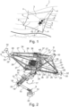
- Fig. 1 shows a perspective view of an embodiment of a robotic system 1 comprising a robot 2.
- the robot 2 is suspended from four cables 3, such that one end of each cable 3 is fixed on to a respective external body 4, for example a respective tree or a respective pole.
- the other end of each cable 3 is attached to a respective pulley, as shown in Figs. 6 to 10 , such that the robot 2 is movable within at least one work plane in the work space 5 between the four external bodies 4.
- Such a robot 2 is adapted to move on terrains 7 of arbitrary inclinations 8, for example mountainous terrains, marshy terrains, rocky terrains or flat terrains.
- the robot 2 is a part of a manipulation device 6.
- the manipulation device 6 comprises a manipulation unit 9 mechanically connected to the robot 2 for manipulating objects 10, for example a tree.
- the manipulating unit 9 is a pruning device 11 for cutting certain dried-up branches of the tree, which is the object in this case.
- the manipulation device 6, that is the robot 2 is movable such that the manipulating unit 9 could optimally reach to the desired point of the object 10, which needs to be manipulated as per requirement.
- Fig. 2 depicts a schematic view of an embodiment of the manipulation device 6 comprising the robot 2 and the manipulating unit 9 connected to the robot 2.
- the manipulating unit 9 is a camera 12.
- the manipulating unit 9 is connected to the robot 2 by means of a mechanical arm 13.
- the mechanical arm 13 is attached to the robot 2 at one end and comprises the camera 12 on the other end.
- the mechanical arm 13 comprises a first section 14 and a second section 15, the first section 14 is connected to the robot 2 at a first end 16, such that the first section 14 is rotatable along a direction depicted by the first rotation arrow 17, said rotational motion can be realized by means of a bevel gear arrangement 34.
- the second end 18 of the first section 14 is connected to a first end 19 of the second section 15, such that the second section 15 is rotatable in a direction depicted by the second rotation arrow 20, said rotational motion can be realized by means of a belt drive arrangement 23.
- the second end 21 of the second section 15 is connected to the camera 12, such that the camera 12 is rotatable in a direction depicted by the third rotation arrow 22.
- the manipulation device 6 is configured such that the manipulating unit 9 can optimally operate on a required point by means of the degrees of freedom offered to the movement and positioning of the manipulating unit 9 by means of the mechanical arm 13 in addition to the movement of the robot 2 suspended by the four cables 3, as shown in Fig. 1 , so that the robot 2 can be optimally moved with the work space 5 as per requirement.
- the robot 2 comprises a diamond-shaped frame 24 enclosing a frame space 25.
- the diamond-shaped frame 24, is in form of a pyramid with a square base.
- the square base is formed by means of base connecting rods 26, whereas the pyramid shape is formed by means of side connecting rods 27, such that one end of each of the side connecting rods 27 is connected to a respective end of corresponding base connecting rods 26.
- the connections are depicted by the frame ends 28.
- the other ends of the side connecting rods 27 are connected to the casing 40 enclosed within the frame space 25.
- Each frame end 28 comprises a respective cable guide 29, each of which is configured to receive a respective cable 3, to pass through a guide respective guide structure 30 via a corresponding cable duct 31.
- Each guide structure 30 is configured to rotate along directions depicted by a fourth rotation arrow 32, wherein the angle of rotation of the guide structure 30 along the fourth rotation arrow 32 can range between -45° to +45°.
- each guide structure 30 is configured to rotate along directions depicted by a fifth rotation arrow 33 in a plane of rotation normal to the plane of rotation depicted by the fourth rotation arrow 32, wherein the angle of rotation of the guide structure 30 along the fifth rotation arrow 33 can range between -75° to +75°.
- the guide structure 30 provides two degrees of freedom for the positioning of the corresponding cable 3 passing through the respective guide structure 30. Furthermore, the guide structure 30 can comprise rotary encoders, not shown in figures, to measure cable directions with the rotary encoders in order to locate the robot 2 in the work space 5.
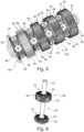
- the robot 2 further comprises four actuators 36, as shown in Fig. 4 . Each actuator 36 is configured to rotate at least one pulley 35.
- the robot 2 comprises an actuator controller 37.
- the robot 2 comprises an actuator fan 38, for example for cooling the actuators 36 as well as the actuator controller 37.
- the robot 2 further comprises an electronic control unit 39 including a processor, which may be configured to control the movement and positioning of the robot 2 and that of the manipulating unit 9 as per requirement for a treatment of the manipulating object 10.
- the four actuators 36, the four pulleys 35, four motors 41, wherein each motor 41 is configured to drive each of the corresponding actuator 36, the actuator controller 37 and the electronic control unit 39 are installed within the casing 40.
- each pulley 35 is adapted to wind up or wind out the corresponding attached cable 3.
- the pulley 35 comprises a cylindrical outer pulley wall 45 and a cylindrical inner pulley wall 46.
- the cylindrical outer pulley wall 45 and the cylindrical inner pulley wall 46 are concentric to each other.
- the cylindrical outer pulley wall 45 and the cylindrical inner pulley wall 46 enclose a first pulley space 47 and the cylindrical inner pulley wall 46 encloses a second pulley space 48 enclosing a center of the pulley 35.
- One of the cables 3 is attached to an outer surface of the cylindrical outer pulley wall 45 and is wound around the outer surface of the cylindrical outer pulley wall 45.
- a plurality of internal bevel gears 49 are embedded within the first pulley space 47, wherein a respective axis of rotation of each of the respective internal bevel gear 49 is directed in a radial direction towards the center of the respective pulley 35.
- Each internal bevel gear 49 is rotationally mounted within the first pulley space 47 inside the respective pulley 35, such that the axis of rotation of each respective internal bevel gear 49 is directed radially.
- Further spokes 50 are mounted within the first pulley space 47, such that each spoke 50 is arranged between to radially neighboring internal bevel gears 49.
- Each spoke 50 is directed in the radial direction and joins the cylindrical outer pulley wall 45 and the cylindrical inner pulley wall 46.
- the plurality of spokes 50 provide additional structural strength to the corresponding pulley 35.
- the robot 2 comprises four pulleys 35 and four transmissions 42, wherein the cylindrical outer pulley wall 45 and the cylindrical inner pulley wall 46 of each pulley are omitted for the sake of understandability.
- the transmission 42 is a differential gear 43.
- the robot 2 comprises a plurality of coaxial bevel gears 44, wherein each pulley 35 is coaxially arranged between two coaxial bevel gears 44.
- the teeth of the respective coaxial bevel gear are directed radially with an axial directed inclination at the center of the respective coaxial bevel gear 44.
- the tooth-bearing face of the coaxial bevel gear 44 is conically shaped.
- the differential gear 43 comprises the plurality of internal bevel gears 49 of the pulley, which is arranged between two coaxial bevel gears 44.
- the two coaxial bevel gears 44 on either side of the pulley are arranged such that the conically shaped tooth-bearing face of the respective coaxial bevel gear 44 faces the pulley 35 therebetween.
- the axis of rotation of the internal bevel gear 49 is be orthogonal to the axis of rotation of the neighboring coaxial bevel gears 44, each on either side of the pulley 35.
- the internal bevel gears 49 are configured to engage with the two neighboring coaxial bevel gears 44, to form the differential gear 43, such that the rotational speed of each of the respective internal bevel gear 49 about its axis is an average of the rotational speeds of the two neighboring coaxial bevel gears 44.
- each internal bevel gear 49 is fixed to an internal side of the cylindrical outer pulley wall 45 of the respective pulley 35, whereas the other end of the axis of each of the internal bevel gears 49 is fixed to an outer side of the cylindrical inner pulley wall 46, wherein said outer side of the cylindrical inner pulley wall 46 faces the first pulley space 47.
- the rotational speed of the pulley 35 is dependent on the rotational speed of the internal bevel gear 44, the rotational speed of the pulley 35 would also be an average of the rotational speeds of the two neighboring coaxial bevel gears 44. This in turn would enable a winding up or winding down of the cable 3 wound on the outer surface of the cylindrical outer pulley wall 45 to be released or withdrawn at rate at which the respective pulley 35 rotates. In other words, the rate at which the cable 3, that is wound around the pulley 35, is released or withdrawn is proportional to the average of the rotational speeds of the corresponding neighboring coaxial bevel gears 44 of said pulley 35.
- a gear unit 52 is formed by fixing to coaxial bevel gears 44 and a coaxial spur gear 53 therebetween, such that the respective tooth-bearing face of each of the two coaxial bevel gears 44 faces a respective side, that is opposite to the side where the corresponding coaxial spur gear 53 is arranged therebetween.
- the gear unit 52 has a cylindrical structure with an outwardly conical shaped front side comprising a coaxial bevel gear 44, wherein a normal to said front side is parallel to the axis of the gear unit 52 or the corresponding coaxial bevel gear 44.
- the gear unit 52 comprises an outwardly conical shaped back side comprising another coaxial bevel gear 44, wherein a normal to said front side is parallel to the axis of the gear unit 52 or the corresponding coaxial bevel gear 44.
- the gear unit 52 comprises a coaxial spur gear 53, which is fixed between each of the aforementioned two coaxial bevel gears 44, such that the coaxial spur gear 53 forms the curved side of the cylindrical structure of the gear unit 52.
- the tooth-bearing face of the coaxial spur gear are directed in an axial direction which is parallel to the axis of rotation of the corresponding gear unit 52.
- the coaxial spur gear 53 is fixed to each coaxial bevel gear 44 on either side by means of screws 54. Other fixing means known to a person skilled in the art, such as nails or welding can also be used to fix the coaxial spur gear 53 with the coaxial bevel gears 44.
- the gear unit 52 can be also produced as a single unit, for example using molding.
- the tooth-bearing face of the respective coaxial bevel gear 44 comprises a circular space 51 around its respective center, such that the diameter of the circular space 51 equal to the diameter of the second pulley space 48.
- the robot 2 comprises a shaft 55 which passes through the coaxial bevel gears 44 and the pulleys 35.
- the diameter of the shaft 55 is chosen such that the shaft 55 passes through the second space of the respective pulley 35 as well as the circular space 51 of the respective coaxial bevel gear 44.
- the coaxial bevel gears 44, the gear units 52 comprising the coaxial bevel gears 44 and the coaxial spur gear 53, respectively, and the pulleys 35 arranged between two coaxial bevel gears 44 or between two gear units 52 are arranged coaxially on the shaft 55, and are arranged in form of a cylindrical unit 56.
- the robot 2 comprises four actuators 36 and a cylindrical unit 56.
- the cylindrical unit 56 comprises four gear units 52 including a first gear unit 57, a second gear unit 58, a third gear unit 59 and a fourth gear unit 60.
- a first pulley 61 is arranged between the first gear unit 57 and the second gear unit 58
- a second pulley 62 is arranged between the second gear unit and the third gear unit 59
- a third pulley 63 is arranged between the third gear unit 59 and the fourth gear unit 60
- a fourth pulley 64 is arranged between the fourth gear 60 and an end coaxial bevel gear 65.
- the four actuators 36 include a first actuator 66, a second actuator 67, a third actuator 68 and fourth actuator 69.
- Each actuator 36 is connected to a corresponding gear unit 52 by means of an actuator transmission 70 such that each actuator 36 is configured to rotate at least one of the pulleys 35, and wherein each pulley 35 is configured to rotate by means of at least one actuator 36 via the corresponding differential gear 43.
- the actuator transmission 70 comprises an actuator spur gear 71 and a coaxial spur gear 53 engaging with each other, wherein the coaxial spur gear 53 is configured to engage with the respective coaxial bevel gear 44, such that rotational motion of the actuator 36 is transferrable to said respective coaxial bevel gear 44.
- the actuator spur gear 71 of the first actuator 66 engages with the coaxial spur gear 53 of the fourth gear unit 60, so that the rotational motion of the first actuator 66 is transferred to the respective coaxial bevel gears 44 of the fourth gear unit 60.
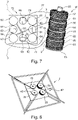
- This connection of the first actuator 66 with the fourth gear unit 60 is depicted by the first connection line 75 in mechanical connection diagram 72 of Fig. 7 .
- the actuator spur gear 71 of the second actuator 67 engages with the coaxial spur gear 53 of the second gear unit 58, so that the rotational motion of the second actuator 67 is transferred to the respective coaxial bevel gears 44 of the second gear unit 58.
- This connection of the second actuator 67 with the second gear unit 58 is depicted by the second connection line 76 in mechanical connection diagram 72.
- the actuator spur gear 71 of the third actuator 68 engages with the coaxial spur gear 53 of the first gear unit 57, so that the rotational motion of the third actuator 68 is transferred to the respective coaxial bevel gears 44 of the first gear unit 57.
- This connection of the third actuator 68 with the first gear unit 57 is depicted by the third connection line 77 in mechanical connection diagram 72.
- the actuator spur gear 71 of the fourth actuator 69 engages with the coaxial spur gear 53 of the third gear unit 59, so that the rotational motion of the fourth actuator 69 is transferred to the respective coaxial bevel gears 44 of the third gear unit 59.
- This connection of the fourth actuator 69 with the third gear unit 59 is depicted by the fourth connection line 78 in mechanical connection diagram 72.
- the first pulley 61 is arranged between the first gear unit 57 and the second gear unit 58, such that the internal bevel gears 49 of the first pulley 61 are engaged with the coaxial bevel gear 44 of the first gear unit 57 as well as with the coaxial bevel gear 44 of the second gear unit 58.
- the rotational speed of the first pulley 61 would be an average of the rotational speed of the coaxial bevel gear 44 of the first gear unit 57 and that of the coaxial bevel gear 44 of the second gear unit 58.
- the first pulley 61 is configured to rotate by means of the third actuator 66 which is connected to the first gear unit 57, as depicted by the third connection line 77.
- first pulley 61 is also configured to rotate by means of the second actuator 67 which is connected to the second gear unit 58, as is depicted by the second connection line 76.
- the activation of the rotation of the first pulley 61 by means of the third actuator 68 is shown by the first activation line 79, whereas the activation of the rotation of the first pulley 61 by means of the second actuator 67 is shown by the second activation line 80.
- the fourth pulley 64 is arranged between the second gear unit 58 and the third gear unit 59, such that the internal bevel gears 49 of the fourth pulley 64 are engaged with the coaxial bevel gear 44 of the second gear unit 58 as well as with the coaxial bevel gear 44 of the third gear unit 59.
- the rotational speed of the fourth pulley 64 would be an average of the rotational speed of the coaxial bevel gear 44 of the second gear unit 58 and that of the coaxial bevel gear 44 of the third gear unit 59.
- the fourth pulley 64 is configured to rotate by means of the second actuator 67 which is connected to the second gear unit 58, as depicted by the second connection line 76.
- the fourth pulley 64 is also configured to rotate by means of the fourth actuator 69 which is connected to the third gear unit 59, as depicted by the fourth connection line 78.
- the activation of the rotation of the fourth pulley 64 by means of the second actuator 67 is shown by the third activation line 81, whereas the activation of the rotation of the fourth pulley 64 by means of the fourth actuator 69 is shown by the fourth activation line 82.
- the second pulley 62 is arranged between the third gear unit 59 and the fourth gear unit 60, such that the internal bevel gears 49 of the second pulley 62 are engaged with the coaxial bevel gear 44 of the third gear unit 59 as well as with the coaxial bevel gear 44 of the fourth gear unit 60.
- the rotational speed of the second pulley 62 would be an average of the rotational speed of the coaxial bevel gear 44 of the third gear unit 59 and that of the coaxial bevel gear 44 of the fourth gear unit 60.
- the second pulley 62 is configured to rotate by means of the fourth actuator 67, which is connected to the third gear unit 59, as depicted by the fourth connection line 78.
- the second pulley 62 is also configured to rotate by means of the first actuator 66, which is connected to the fourth gear unit 60, as is depicted by the first connection line 75.
- the activation of the rotation of the second pulley 62 by means of the fourth actuator 69 is shown by the fifth activation line 83, whereas the activation of the rotation of the second pulley 62 by means of the first actuator 66 is shown by the sixth activation line 84.
- a first coupling 96 between the second gear unit 58 and the end coaxial bevel gear 65 is depicted, especially the first coupling 96 between the first actuator 66 and the second actuator 67 is shown.
- the second gear unit 58 comprising two coaxial bevel gears 44 and one coaxial spur gear 53 is rotationally fixed on a first section 73 of the shaft 55, whereas the end coaxial bevel gear 65 is rotationally fixed on a second section 74 of the shaft 55. This means that when the second gear unit 58 is rotated by means of the second actuator 58 at a rotational speed, the end coaxial bevel gear 65 would also rotate with the same rotational speed.
- the third pulley 63 is arranged between the fourth gear unit 60 and the end coaxial bevel gear 65, such that the internal bevel gears 49 of the third pulley 63 are engaged with the coaxial bevel gear 44 of the fourth gear unit 60 as well as with the end coaxial bevel gear 65.
- the rotational speed of the third pulley 63 would be an average of the rotational speed of the coaxial bevel gear 44 of the fourth gear unit 60 and that of the end coaxial bevel gear 65.
- an activation of the rotation of the second gear unit 58 by means of the second actuator 67 would also enable an activation of the rotation of the end coaxial bevel gear 65.
- the third pulley 63 is configured to rotate by means of the second actuator 67, which is connected to the second gear unit 58. This in turn enables to rotate the end coaxial bevel gear 65 by means of the first coupling 96. Further, the third pulley 63 is configured to rotate by means of the first actuator 66, which is connected to the fourth gear unit 60, as depicted by the first connection line 75.
- the activation of the rotation of the third pulley 63 by means of the second actuator 67 is shown by the seventh activation line 85, whereas the activation of the rotation of the third pulley 63 by means of the first actuator 66 is shown by the eighth activation line 86.
- the robot 2 comprises a plurality of pulleys 35, which can also be referred to as drums, a plurality of transmissions 42 and plurality of actuators 36.
- Each transmission 42 is a cable-pulley mechanism 87, which can also be referred to as a cable-coupled mechanism.
- the cable-pulley mechanism 87 includes a first cable-pulley mechanism 88 comprising two pulleys 35, wherein each pulley 35 is attached to a respective cable 3, which is wound on each of the respective pulley 35 of the first cable-pulley mechanism 88.
- the first cable-pulley mechanism 88 is coaxially and rotationally fixed to a first coaxial actuator 89, which is configured to rotate the first cable-pulley mechanism 88, for example by means of a motor 41 included within the first coaxial actuator 89.
- the cable-pulley mechanism 87 includes a second cable-pulley mechanism 90 comprising three pulleys 35, wherein each pulley 35 is attached to a respective cable 3, which is wound on each of the respective pulley 35 of the second cable-pulley mechanism 90.
- the second cable-pulley mechanism 90 is coaxially and rotationally fixed to a second coaxial actuator 91, which is configured to rotate the second cable-pulley mechanism 90, for example by means of a motor included within the second coaxial actuator 91.
- the cable-pulley mechanism 87 includes a third cable-pulley mechanism 92 comprising one pulley 35, wherein the one pulley 35 is attached to a corresponding cable 3, which is wound on the corresponding pulley 35 of the third cable-pulley mechanism 92.
- the third cable-pulley mechanism 92 is coaxially and rotationally fixed to a third coaxial actuator 93, which is configured to rotate the third cable-pulley mechanism 92, for example by means of a motor included within the third coaxial actuator 93.
- the cable-pulley mechanism 87 includes a fourth cable-pulley mechanism 94 comprising two pulleys 35, wherein each pulley 35 is attached to a respective cable 3, which is wound on the corresponding pulley 35 of the fourth cable-pulley mechanism 94.
- the fourth cable-pulley mechanism 94 is coaxially and rotationally fixed to a fourth coaxial actuator 95, which is configured to rotate the fourth cable-pulley mechanism 94, for example by means of a motor included within the fourth coaxial actuator 95.
- a coupling 96 between the four coaxial actuators 88, 91, 93 and 95 is shown.
- the first cable 97 is connected to the single pulley 35 of the third cable-pulley mechanism 92 and a first of the three pulleys 35 of the second cable-pulley mechanism 90 via the first guiding pulley 98, wherein the first guiding pulley 98 is adapted to be attached the first external body 99.
- the third coaxial actuator 93 is coupled to the second coaxial actuator 91 by means of the first cable 97.
- the second cable 100 is connected to a second of the two pulleys 35 of the second cable-pulley mechanism 90 and a first of the two pulleys 35 of the first cable-pulley mechanism 88 via the fourth guiding pulley 107, wherein the fourth guiding pulley 107 is adapted to be attached the fourth external body 108.
- the second coaxial actuator 91 is coupled to the first coaxial actuator 89 by means of the second cable 100.
- the third cable 103 which is connected to a second of the two pulleys 35 of the first cable-pulley mechanism 88 and a second of the two pulleys 35 of the fourth cable-pulley mechanism 94 via the second guiding pulley 101, wherein the second guiding pulley 101 is adapted to be attached the second external body 108.
- the first coaxial actuator 89 is coupled to the fourth coaxial actuator 95 by means of the third cable 103.
- the fourth cable 106 is connected to a second of the two pulleys 35 of the fourth cable-pulley mechanism 94 and a third of the three pulleys 35 of the second cable-pulley mechanism 90 via the second guiding pulley 101, wherein the third guiding pulley 104 is adapted to be attached the third external body 106.
- the fourth coaxial actuator 94 is coupled to the second coaxial actuator 91 by means of the fourth cable 106.
- the coupling 96 of four coaxial actuators 88, 91, 93 and 95 is depicted by the coupling matrix Q.
- the inventive robot 2 as well as the robotic system 1 comprising said robot 2, the manipulation device 6 comprising said robotic system 1 and the method for manipulating objects 10, in particular for processing plants, enable a minimization of an overall energy consumption by reducing actuator torques, current and thus, heat dissipation.
Landscapes
- Engineering & Computer Science (AREA)
- General Engineering & Computer Science (AREA)
- Mechanical Engineering (AREA)
- Robotics (AREA)
- Manipulator (AREA)
Priority Applications (2)
| Application Number | Priority Date | Filing Date | Title |
|---|---|---|---|
| EP21199312.6A EP4155033A1 (de) | 2021-09-28 | 2021-09-28 | Roboter, robotisches system, und verfahren zum manipulieren von objekten mit diesem robotischen system |
| PCT/EP2022/071614 WO2023051975A1 (en) | 2021-09-28 | 2022-08-02 | Robot, robotic system, manipulation device and method for manipulating objects |
Applications Claiming Priority (1)
| Application Number | Priority Date | Filing Date | Title |
|---|---|---|---|
| EP21199312.6A EP4155033A1 (de) | 2021-09-28 | 2021-09-28 | Roboter, robotisches system, und verfahren zum manipulieren von objekten mit diesem robotischen system |
Publications (1)
| Publication Number | Publication Date |
|---|---|
| EP4155033A1 true EP4155033A1 (de) | 2023-03-29 |
Family
ID=77998818
Family Applications (1)
| Application Number | Title | Priority Date | Filing Date |
|---|---|---|---|
| EP21199312.6A Withdrawn EP4155033A1 (de) | 2021-09-28 | 2021-09-28 | Roboter, robotisches system, und verfahren zum manipulieren von objekten mit diesem robotischen system |
Country Status (2)
| Country | Link |
|---|---|
| EP (1) | EP4155033A1 (de) |
| WO (1) | WO2023051975A1 (de) |
Cited By (1)
| Publication number | Priority date | Publication date | Assignee | Title |
|---|---|---|---|---|
| US20220009532A1 (en) * | 2020-02-14 | 2022-01-13 | Georgia Tech Research Corporation | Wire-Traversing Robot and Method of Operation |
Citations (5)
| Publication number | Priority date | Publication date | Assignee | Title |
|---|---|---|---|---|
| US6873355B1 (en) | 1998-08-07 | 2005-03-29 | Skycam, Llc | Three-dimensional moving camera assembly with an informational cover housing |
| WO2016132284A1 (en) | 2015-02-20 | 2016-08-25 | Airnamics D.O.O. | System for moving a platform and a useful load in space by using cables and drums arranged on the platform |
| EP3318369A1 (de) | 2016-11-08 | 2018-05-09 | Centre National De La Recherche Scientifique | Kabelbetriebener parallelmanipulator |
| US20200047332A1 (en) * | 2017-04-26 | 2020-02-13 | The Board Of Trustees Of The Leland Stanford Junior University | Cabled differential for cable controlled joint |
| WO2021144685A1 (en) * | 2020-01-13 | 2021-07-22 | Alma Mater Studiorum - Universita' Di Bologna | Robotic arrangement with parallel architecture |
-
2021
- 2021-09-28 EP EP21199312.6A patent/EP4155033A1/de not_active Withdrawn
-
2022
- 2022-08-02 WO PCT/EP2022/071614 patent/WO2023051975A1/en not_active Ceased
Patent Citations (5)
| Publication number | Priority date | Publication date | Assignee | Title |
|---|---|---|---|---|
| US6873355B1 (en) | 1998-08-07 | 2005-03-29 | Skycam, Llc | Three-dimensional moving camera assembly with an informational cover housing |
| WO2016132284A1 (en) | 2015-02-20 | 2016-08-25 | Airnamics D.O.O. | System for moving a platform and a useful load in space by using cables and drums arranged on the platform |
| EP3318369A1 (de) | 2016-11-08 | 2018-05-09 | Centre National De La Recherche Scientifique | Kabelbetriebener parallelmanipulator |
| US20200047332A1 (en) * | 2017-04-26 | 2020-02-13 | The Board Of Trustees Of The Leland Stanford Junior University | Cabled differential for cable controlled joint |
| WO2021144685A1 (en) * | 2020-01-13 | 2021-07-22 | Alma Mater Studiorum - Universita' Di Bologna | Robotic arrangement with parallel architecture |
Cited By (2)
| Publication number | Priority date | Publication date | Assignee | Title |
|---|---|---|---|---|
| US20220009532A1 (en) * | 2020-02-14 | 2022-01-13 | Georgia Tech Research Corporation | Wire-Traversing Robot and Method of Operation |
| US11866079B2 (en) * | 2020-02-14 | 2024-01-09 | Georgia Tech Research Corporation | Wire-traversing robot and method of operation |
Also Published As
| Publication number | Publication date |
|---|---|
| WO2023051975A1 (en) | 2023-04-06 |
Similar Documents
| Publication | Publication Date | Title |
|---|---|---|
| US8511197B2 (en) | Robot arm assembly | |
| JP4964190B2 (ja) | パラレルメカニズム | |
| WO2012059791A1 (en) | Robotic snake-like movement device | |
| US12281678B2 (en) | Tethered payload motion control and cable robot using magnetorheological actuators | |
| EP3469230B1 (de) | Kinematische kette zur übertragung von mechanischen drehmomenten | |
| CN111673715A (zh) | 机器人 | |
| EP4155033A1 (de) | Roboter, robotisches system, und verfahren zum manipulieren von objekten mit diesem robotischen system | |
| US20220331036A1 (en) | Surgical tool, surgery support system, and surgical operating unit | |
| CN115488873A (zh) | 一种少输入的绳驱动变刚度七自由度机械臂 | |
| US20210031383A1 (en) | Mechanism with three degrees-of-freedom (dof) output to provide independent control over roll, pitch, and yaw of output structure | |
| CN105798947B (zh) | 可重构的绳驱动串联解耦机械臂关节及其工作方法 | |
| US6267356B1 (en) | Apparatus and a method for use in handling a load | |
| JPS63289366A (ja) | 運動変換装置 | |
| JP6687928B2 (ja) | 関節駆動装置及び多軸マニュピレータ | |
| CN105798900B (zh) | 基于轮系的绳驱动解耦机构及其解耦方法 | |
| JP2007319954A (ja) | 可動軸駆動装置およびロボット装置 | |
| JPH0451312B2 (de) | ||
| JPS6216796B2 (de) | ||
| KR102897202B1 (ko) | 케이블 로봇용 컴팩트 윈치 모듈 | |
| CN217256391U (zh) | 机械肩关节、机械臂及机器人 | |
| CN205704261U (zh) | 可重构的绳驱动串联解耦机械臂回转关节及俯仰旋转关节 | |
| KR102782209B1 (ko) | 웨어러블 로봇용 케이블 구동 회전 관절 장치 | |
| KR20230140761A (ko) | 케이블 로봇용 컴팩트 윈치 모듈 | |
| KR102609029B1 (ko) | 로봇을 위한 경량 관절 장치 | |
| JPS6260235B2 (de) |
Legal Events
| Date | Code | Title | Description |
|---|---|---|---|
| PUAI | Public reference made under article 153(3) epc to a published international application that has entered the european phase |
Free format text: ORIGINAL CODE: 0009012 |
|
| STAA | Information on the status of an ep patent application or granted ep patent |
Free format text: STATUS: THE APPLICATION HAS BEEN PUBLISHED |
|
| AK | Designated contracting states |
Kind code of ref document: A1 Designated state(s): AL AT BE BG CH CY CZ DE DK EE ES FI FR GB GR HR HU IE IS IT LI LT LU LV MC MK MT NL NO PL PT RO RS SE SI SK SM TR |
|
| STAA | Information on the status of an ep patent application or granted ep patent |
Free format text: STATUS: THE APPLICATION IS DEEMED TO BE WITHDRAWN |
|
| 18D | Application deemed to be withdrawn |
Effective date: 20230930 |