EP4090218B1 - Handgriff mit einem mechanismus zur steuerung der beugung des kopfes eines medizinischen endoskops - Google Patents
Handgriff mit einem mechanismus zur steuerung der beugung des kopfes eines medizinischen endoskops Download PDFInfo
- Publication number
- EP4090218B1 EP4090218B1 EP20853533.6A EP20853533A EP4090218B1 EP 4090218 B1 EP4090218 B1 EP 4090218B1 EP 20853533 A EP20853533 A EP 20853533A EP 4090218 B1 EP4090218 B1 EP 4090218B1
- Authority
- EP
- European Patent Office
- Prior art keywords
- handle
- pivoting part
- casing
- shell
- rotation
- Prior art date
- Legal status (The legal status is an assumption and is not a legal conclusion. Google has not performed a legal analysis and makes no representation as to the accuracy of the status listed.)
- Active
Links
Images

Classifications
-
- A—HUMAN NECESSITIES
- A61—MEDICAL OR VETERINARY SCIENCE; HYGIENE
- A61B—DIAGNOSIS; SURGERY; IDENTIFICATION
- A61B1/00—Instruments for performing medical examinations of the interior of cavities or tubes of the body by visual or photographical inspection, e.g. endoscopes; Illuminating arrangements therefor
- A61B1/00112—Connection or coupling means
- A61B1/00121—Connectors, fasteners and adapters, e.g. on the endoscope handle
-
- A—HUMAN NECESSITIES
- A61—MEDICAL OR VETERINARY SCIENCE; HYGIENE
- A61B—DIAGNOSIS; SURGERY; IDENTIFICATION
- A61B1/00—Instruments for performing medical examinations of the interior of cavities or tubes of the body by visual or photographical inspection, e.g. endoscopes; Illuminating arrangements therefor
- A61B1/00064—Constructional details of the endoscope body
- A61B1/00066—Proximal part of endoscope body, e.g. handles
-
- A—HUMAN NECESSITIES
- A61—MEDICAL OR VETERINARY SCIENCE; HYGIENE
- A61B—DIAGNOSIS; SURGERY; IDENTIFICATION
- A61B1/00—Instruments for performing medical examinations of the interior of cavities or tubes of the body by visual or photographical inspection, e.g. endoscopes; Illuminating arrangements therefor
- A61B1/00112—Connection or coupling means
- A61B1/00121—Connectors, fasteners and adapters, e.g. on the endoscope handle
- A61B1/00124—Connectors, fasteners and adapters, e.g. on the endoscope handle electrical, e.g. electrical plug-and-socket connection
-
- A—HUMAN NECESSITIES
- A61—MEDICAL OR VETERINARY SCIENCE; HYGIENE
- A61B—DIAGNOSIS; SURGERY; IDENTIFICATION
- A61B1/00—Instruments for performing medical examinations of the interior of cavities or tubes of the body by visual or photographical inspection, e.g. endoscopes; Illuminating arrangements therefor
- A61B1/005—Flexible endoscopes
- A61B1/0051—Flexible endoscopes with controlled bending of insertion part
- A61B1/0052—Constructional details of control elements, e.g. handles
-
- A—HUMAN NECESSITIES
- A61—MEDICAL OR VETERINARY SCIENCE; HYGIENE
- A61B—DIAGNOSIS; SURGERY; IDENTIFICATION
- A61B1/00—Instruments for performing medical examinations of the interior of cavities or tubes of the body by visual or photographical inspection, e.g. endoscopes; Illuminating arrangements therefor
- A61B1/012—Instruments for performing medical examinations of the interior of cavities or tubes of the body by visual or photographical inspection, e.g. endoscopes; Illuminating arrangements therefor characterised by internal passages or accessories therefor
- A61B1/015—Control of fluid supply or evacuation
Definitions
- the present invention relates to the technical field of medical endoscopes in the general sense allowing access to the interior of a hollow organ, a cavity or a natural or artificial conduit of the human body in order to carry out various operations for therapeutic, surgical or diagnostic purposes.
- the present invention relates more specifically to the control handle of such endoscopes, adapted to remain outside the hollow organ, cavity or duct to be inspected and equipped in particular with a mechanism for controlling the flexion of the head of a medical endoscope.
- an endoscope comprises a control handle in the form of a housing adapted to be held by a user of the endoscope and to which is attached a tubular structure designed to be inserted into a body cavity of a patient to be examined.
- This tubular insertion structure comprises a distal head equipped with a vision system for illuminating and examining the organ, cavity or duct of the human body. Upstream of the distal head, the tubular insertion structure comprises a deflection portion controlled by a control handle mechanism to orient the distal head within the insertion path.
- the handle comprises a lever movable along a curved path and connected to a lever which can pivot about a pivot axis and acts on two control wires to ensure the flexion of the distal head.
- the patent application WO 2011/089349 describes an endoscope having a system for actuating the distal head of the insertion tube having pulleys mounted coaxially in the housing of the control handle. These pulleys are rotated by rotary control levers extending laterally and on the rear of the handle.
- actuating the control button is a delicate operation to be carried out by the operator given that the operator must firmly hold the control handle during the inspection operation.
- the user has difficulty in exerting on the control button an effort adapted to ensure the flexion of the distal head while holding the handle.
- An additional difficulty arises when the user must also act on the device for closing off a fluid circulation circuit to bring fluids or to suck fluids at the distal head.
- the present invention therefore aims to remedy the drawbacks of the state of the art by proposing a new control handle for a medical endoscope, designed to facilitate the control operations aimed at ensuring the flexion of the distal head.
- the handle for a medical endoscope comprises the features of claim 1, namely a housing having two opposite main faces and provided with a mechanism for controlling the flexion of a distal head of the medical endoscope, this control mechanism comprising at least one actuating member of a pivoting part produced in the form of an actuating ring having an axial ferrule having a cylindrical external surface cooperating with an annular bearing to be guided in rotation by this annular bearing, along a transverse axis of rotation and the rotation of which causes the flexion of the distal head, the axial ferrule having an internal bore partly delimiting an opening cylindrical configured for the insertion of a finger and which passes right through the housing, opening through internal bores on the two opposite main faces of the housing, the pivoting part and the annular bearing being arranged to be located outside the cylindrical opening.
- the cylindrical opening has a passage section of between 8 x 8 mm and 30 x 30 mm and preferably between 8 x 8 mm and 25 x 25 mm.
- the pivoting part is guided in movement by a pivot connection around a transverse axis of rotation coinciding with the transverse axis of the cylindrical opening, the pivoting part being blocked in translation on one side, by the annular bearing mounted integrally with a first half-shell of the housing and on the other side, by a second half-shell of the housing.
- the axial ferrule of the actuating ring has at its free end a support edge cooperating with a stop edge of a neck of the annular bearing to together form an empty cylinder internally delimiting the cylindrical opening.
- the actuating member is part of an annular collar fixed to the pivoting part and having an internal bore of section identical to the internal bore of the axial ferrule to form with the axial ferrule and the neck of the bearing, an empty cylinder internally delimiting the cylindrical opening.
- first half-shell and the second half-shell of the housing are fixed together.
- pivoting part is blocked transversely in one direction, by a stop edge of the annular bearing arranged or fixed on the first half-shell and in the other direction, by being in abutment on the second half-shell of the housing.
- the actuating member is a lever mounted integral with the pivoting part guided in rotation so as to move the pivoting part in rotation by a rotational movement of the lever.
- the lever comprises an actuating arm extending parallel to the transverse axis of rotation and externally to the housing, between the two main faces of the housing.
- the actuating member is part of an annular collar delimited by a bore mounted integral with the pivoting part while abutting the second half-shell of the housing.
- the actuating member is guided in linear movement and acts on the pivoting part using a system for transforming the linear movement of the control member into a rotational movement of the pivoting part.
- At least one control cable for flexion of the distal head is mounted inside the control handle, the pivoting part acting directly or by a motion transformation system, on at least said control cable for flexion of the distal head.
- the housing comprises a first housing for a fluid circulation circuit and a second housing for an electric cable, a part of these housings passing on either side of the cylindrical opening, these housings opening out at a proximal part of the housing.
- Another object of the invention is to provide a medical endoscope comprising a tubular insertion structure supported by a handle according to the invention.
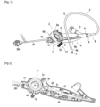
- the subject of the invention relates to a medical endoscope 1 comprising an actuation support 2 such as a control handle equipped with a consumable medical instrument 3.
- This consumable medical instrument 3 which is in contact with human tissues or organs is essentially for single or multiple use by a patient or even for reusable use after decontamination, disinfection and even sterilization.
- the consumable medical instrument 3 is assembled to the handle 2 definitively or temporarily using an assembly system 4.
- the assembly system 4 ensures a complete connection between the handle 2 and the consumable medical instrument 3 or is of the snap-in type to quickly ensure at least a temporary mechanical connection while offering the advantage of allowing easy separation of the consumable medical instrument 3 from the handle 2.
- the consumable medical instrument 3 comprises an external insertion tube 5 having a greater or lesser length and flexibility and intended to be introduced into a natural or artificial access route in order to perform various operations or functions for therapeutic, surgical or diagnostic purposes.
- the insertion tube 5 has a distal portion 7 forming the head of the endoscope 1.
- the insertion tube 5 also comprises a proximal portion 8 opposite the distal portion 7 and extending in projection from the distal end 9i of a housing 9 forming the main body of the handle 2.
- This housing 9 is in the form of an elongated body designed to provide easy gripping of the endoscope.
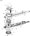
- the housing 9 comprises a first half-shell 9 1 and a second half-shell 9 2 of a shape complementary to the first half-shell 9 1 so as to be able to be assembled or fixed together by any fixing systems such as by snap-fastening for example ( Fig. 5 ).
- the first half-shell 9 1 and the second half-shell 9 2 have C-shaped cross-sections.
- This housing 9 thus has on one side of a median longitudinal plane P, a first main face 9a and on the opposite side of this plane, a second main face 9b. These two opposite main faces 9a, 9b are connected by a peripheral area 9p.
- the handle 2 comprises a mechanism 11 for controlling the flexion of the distal head 7 of the insertion tube 5, making it possible to orient the distal head 7 relative to the longitudinal axis of the insertion tube 5.
- the insertion tube 5 comprises, upstream of the distal head 7, a flexion, folding or bending part 5a allowing the orientation of the distal head 7 relative to the longitudinal axis of the insertion tube 5.
- This flexion, folding or bending part 5a can be produced in any suitable manner to ensure the flexion of the distal head 7 relative to the longitudinal axis of the insertion tube 5.
- this flexion, folding or bending part 6 can be produced by a spring or by tubular vertebrae articulated together.
- the control mechanism 11 comprises at least one actuating member 12 which, following the application of a manual force, causes the flexion of the distal head 7.
- the actuating member 12 is a lever guided in rotation over a limited angular range, along a transverse axis of rotation T.
- the actuating member 12 is a pusher guided in linear movement and subjected to elastic return.
- the actuating member 12 acts on a pivoting part 13 so as to directly or indirectly drive its rotation around the transverse axis of rotation T.
- This pivoting part 13 is connected to the distal head 7 so that a rotation of the pivoting part 13 drives the bending of the distal head 7.
- This pivoting part 13 is guided in rotation by an annular-shaped bearing 14.
- the pivoting part 13 and the annular bearing 14 are arranged to be located outside a cylindrical opening or hole 15 which passes right through the housing 9 to open onto the two opposite main faces 9a, 9b of the housing.
- the cylindrical opening 15 passes completely through the housing 9, opening onto the two opposite main faces 9a, 9b of the housing and corresponding to an empty space.
- the cylindrical opening 15 thus passes through the annular bearing 14, the pivoting part 13, the first half-shell 9 1 and the second half-shell 9 2 .
- the operator can thus insert a finger therein to facilitate the operations of gripping and/or maneuvering the endoscope.
- the cylindrical opening 15 has a circular section with a diameter of between 10 and 40 mm and preferably between 10 mm and 25 mm to allow in particular the insertion of an operator's finger or a hook for suspending the medical endoscope 1.
- the cylindrical opening 15 has a passage section of between 8 mm x 8 mm and 30 mm x 30 mm and preferably between 8 mm x 8 mm and 25 mm x 25 mm.
- the cylindrical opening 15 has a transverse axis which is advantageously coincident with the transverse axis of rotation T of the part. pivoting 13.
- the cylindrical opening 15 has a circular section but it is clear that the section of the cylindrical opening 15 can be of different shape.
- the lever 12 directly drives the pivoting part 13 in rotation about the transverse axis of rotation T.
- the lever 12 is part of an annular collar 12a delimited by an internal bore 12i , intended to be fixed by any suitable means on the pivoting part 13.
- the annular collar 12a comprises lugs 12b adapted to engage in holes 13t provided in the pivoting part 13.
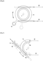
- the lever 12 can be an integral part of the pivoting part 13, as in the variant embodiment illustrated in FIG. Fig. 6 in which the pivoting part 13 is a ring provided radially with an arm forming a lever 12 for rotational actuation.
- the actuating member 12 can indirectly drive the rotation of the pivoting part 13 about the transverse axis of rotation T.
- the actuating member 12 which is a pusher movable in translation and returned to position by a spring 12r, acts on the pivoting part 13 by means of a system for transforming the linear movement of the pusher into a rotational movement of the pivoting part 13.
- This transformation system comprises a pinion 13p and a rack 12c fixed respectively to the pivoting part 13 and to the actuating member 12.
- the actuating member 12 is part of an annular collar 12a mounted around the pivoting part 13 and delimited by an internal bore 12i partly delimiting the cylindrical opening 15 which passes right through the housing.
- the pivoting part 13 is guided by a pivot connection so as to present only a rotational movement around the transverse axis of rotation T.
- the pivoting part 13 can be produced in different ways, considering that the rotational movement of the pivoting part is generally limited to an angular amplitude of less than one turn and in particular, less than a third of a turn.
- the pivoting part 13 is made in the form of a ring comprising a complete or closed ring 13a.
- the pivoting part 13 can be made differently, such as in the form of a half-ring or a portion of a ring in particular, as illustrated according to the variant embodiment of the Fig. 7 For example.
- This ring 13 is guided in rotation by an axial ferrule 13b cooperating with the annular bearing 14.
- This axial ferrule 13b extends in axial projection relative to the ring 13a of the ring while being centered along the transverse axis of rotation T.
- the axial ferrule 13b has a cylindrical outer surface 13e cooperating with the annular bearing 14 to ensure the rotational guidance of the ring.
- the annular bearing 14 has an annular guide formed by a series of axial ribs 14a each having an axial inner edge 14b. These radial inner edges 14b are distributed on a circle centered along the transverse axis of rotation T in order to cooperate with the cylindrical outer surface 13e of the axial ferrule.
- the ring 13a of the ring 13 is delimited at its periphery by an outer edge 13 1 and in its central part, by an inner bore 13 2 .
- the inner bore 13 2 delimits the inner surface of the axial ferrule 13b, which is coaxial with the cylindrical outer surface 13e.
- the ring 13 has an inner bore 13 2 forming a part of the cylindrical opening 15 which passes right through the housing. The pivoting part 13 is thus guided externally by the inside of the annular bearing 14 making it possible to delimit an inner bore 13 2 with a large diameter and corresponding to an empty space.
- the ring 13 has an internal bore 13 2 of section identical to the internal bore 14 1 of the annular bearing 14. It follows that the ring 13 and the annular bearing 14 which are juxtaposed by coming in the extension of one another, together delimit the cylindrical opening 15 which opens into the first half-shell 9 1 and into the second half-shell 9 2 .
- the axial ferrule 13b of the actuating ring cooperates by its bearing edge 13c, with the stop edge 14c of the cylindrical neck 14d of the annular bearing to form together an empty cylinder internally delimiting the cylindrical opening 15.
- the lever 12 is attached by an annular collar 12a fixed to the ring 13.
- the inner bore 12i of the annular collar 12a has a section identical to the inner bore 13 2 of the ring 13 so that the ring 13, the annular bearing 14 and the annular collar 12a together delimit the cylindrical opening 15 which passes right through the housing.
- the annular collar 12a comes by its inner part delimiting the inner bore 12i, in support or in the extension of the axial ferrule 13b, on the side opposite the support edge 13c. It follows that the annular collar 12a delimits by the inner bore 12i with the axial ferrule 13b of the ring 13 and the neck 14d of the bearing, an empty cylinder internally delimiting the cylindrical opening 15.
- the annular bearing 14 is fixed to a main face of the housing and more precisely to the first half-shell 9 1 of the housing.
- the annular bearing 14 is in the form of an attached annular trim and fixed by any suitable means to a half-shell of the housing, for example the first half-shell 9 1 .
- the first half-shell 9 1 has a mounting hole 9' 1 for the trim 14 which comprises, for example, at its periphery, radial lugs 14r blocked axially by tabs 9j arranged on the inner face of the first half-shell 9 1 at the periphery of the mounting hole 9' 1 .
- the ring 13 abuts on the second main face of the housing and more precisely on the second half-shell 9 2 , by means of the annular collar 12a of the actuating member, fixed to the ring 13.
- the annular collar 12a comprises lugs 12e distributed around its periphery to come into abutment against a rim 9c of a hole 9' 2 made in the second half-shell 9 2 .
- the second half-shell 9 2 is made to have a handle or a circular collar 9e forming a projection or a boss and extending axially while being centered on the transverse axis of rotation T and delimiting the mounting hole 9' 2 of circular section.
- the annular collar 12a is therefore mounted inside the mounting hole 9' 2 provided in the second half-shell 9 2 and delimited by the handle or the circular collar 9e.
- the circular handle or collar 9d arranged in the first half-shell 9 1 and the circular handle or collar 9e arranged in the second half-shell 9 2 together form a tubular transverse barrel 9d, 9e crossed by the cylindrical opening 15.
- the housing 9 thus has at its proximal part, the transverse barrel 9d, 9e which extends in the direction of the distal end 9d of the housing 9, by an elongated body.
- the transverse barrel 9d, 9e of the housing 9 is extended in the opposite direction of the distal end 9i, by a proximal nose 9n delimiting the proximal end 9k of the housing.
- the actuating member 12 and in particular the support arm 12p has a non-slip surface, produced for example by the material constituting the support arm 12p (rubber for example) or by a textured surface (by knurling for example).
- This non-slip surface guarantees good grip with the thumb during the crutch phase during the examination despite the practitioner's gloves or fluids that can make the support arm slippery.
- the handle or circular collar 9e of the second half-shell 92 is provided with a notch 9f delimited on either side by shoulders 9g and in which the radial segment 12s of the actuating lever 12 is placed.
- the shoulders 9g thus constitute end-of-travel stops for the actuating lever 12.
- This notch 9f is arranged on a limited portion of the handle or circular collar 9e, for example of the order of 45°, being located in the lower part of the housing when the handle is in the use position.
- the pivoting part 13 acts directly or by a transformation mechanism, on at least one and in the example illustrated two control cables 20 to ensure the flexion of the distal head 7.
- the ends of the cables 20 are fixed to the pivoting part 13 in any suitable manner so that a rotation of the pivoting part 13 causes the flexion of the distal head 7.
- each cable 20 passes through a groove 13g arranged in the outer edge 13 1 of the ring 13.
- the pivoting part 13 thus forms a pivoting annular pulley ensuring for example the left-right or down-up movement of the head 7.
- the cables 20 are made in any suitable manner to ensure this flexion function.
- these cables 20 can be mounted in a sheath and be made of rods, wires or chains, made of a metallic or polymer material for example.
- the actuation cables 20 are mounted inside the control handle 2, exiting therefrom through the distal end 9i to enter inside the insertion tube 5 and to be fixed by their distal ends to the distal part 7 of the insertion tube.
- the proximal ends of the actuation cables 20 are fixed to the pivoting part 13 in any suitable manner.
- the pivoting part 13 is made of two parts assembled together, namely a male annular flange 13' provided with assembly pins and a female annular flange 13" provided with housings for receiving the pins of the male annular flange.
- At least one of the annular flanges 13', 13" is arranged to include two housings 13x adapted to each receive a sleeve crimped onto the end of a cable 20. These housings 13x which are closed during the assembly of the two annular flanges 13', 13" ensure the anchoring of the cables 20 to the pivoting part 13.
- the handle according to the invention has optimized handling ergonomics thanks to the cylindrical opening 15 which corresponds to an empty space crossing the handle housing.
- This cylindrical opening 15 in particular allows good gripping of the handle while providing ease for maneuvering the actuating member 12 which is located near the cylindrical opening 15.
- This cylindrical opening 15 also offers the possibility of hooking the handle onto a hook of any type known per se.
- this handle 2 has a longitudinal symmetry allowing an ambidextrous grip.
- the actuation of the actuating member 12 can be carried out as easily with the left hand as with the right hand.
- this handle 1 offers good resistance to crushing through cooperation with the tubular transverse barrel 9d, 9e of the half-shells, the pivoting part 13 and the annular bearing 14.
- this handle has a reduced weight given the presence of the cylindrical opening 15 making it possible to reduce the mass of the material constituting the half-shells of the housing.
- actuating lever 12 is easily mounted on the pivoting part 13 which is guided in rotation over a large angular range making it possible to obtain precision for the rotation of the pivoting part 13.
- the handle 1 comprises a control mechanism 11 for bending the distal head 7 in one direction, but it is clear that the handle can comprise two control mechanisms 11 for bending the distal head 7 in two perpendicular directions.
- the handle 1 comprises a fluid circulation circuit 22 adapted to bring fluid to the distal head 7 or to suck fluids from the distal head 7.
- This fluid circulation circuit 22 is mounted inside the housing, between the proximal end 9k and the distal end 9i to extend inside the insertion tube 5 to the distal head 7.
- the handle 2 is capable of allowing to illuminate and bring back an image of the distal part 7 of the insertion tube 5.
- an electric cable 24 is mounted inside the housing, between the proximal end and the distal end to extend inside the insertion tube 5 to the distal head 7.
- the housing 9 is arranged to allow the positioning of the fluid circulation circuit 22 on one side of the cylindrical opening 15 and the positioning of the electric cable 24 on the other side of the cylindrical opening 15.
- the housing 9 and in particular the first half-shell 9 1 at the level of the handle or the circular collar 9e is arranged so as to delimit on one side of the mounting hole 9' 1 , a first housing 25 for the passage of the fluid circulation circuit 20 and on the other side of the mounting hole 9' 1 , a second housing 26 for the electric cable 24.
- These housings 25, 26 which each have the shape of a half-crown meet in the elongated part of the housing in which the fluid circulation circuit 20 and the electric cable 24 are mounted.
- the fluid circulation circuit 20 and the electric cable 24 pass through the distal end 9i of the housing to be inserted into the insertion tube 5.
- These housings 25, 26 also meet on the opposite side, to open into the proximal nose 9n of the housing and allow the mounting outside the housing of a connector 24r on the electric cable 24 and of a connector 20r on the fluid circulation circuit 20 for its connection to a source of suction or supply of a fluid.
- the preceding description shows a good balance of the masses inside the handle 2 insofar as in particular the outlets of the fluid circulation circuit 20 and the electric cable 24 are located at the proximal end 9k of the housing, that is to say opposite the distal end 9i of the housing through which the fluid circulation circuit 20 and the electric cable 24 exit.
- the fluid circulation circuit 20 and the electric cable 24 are thus mounted inside the housing 9 from one end 9k to the other end 9i, passing on either side of the cylindrical opening 15. The positioning of these outlets at the proximal end 9k of the housing provides good quality gripping of the handle.
- the fluid circulation circuit 20 is provided with a shutter 30 controlling the opening and closing of the circuit 20 using a control button 31 movable in translation and projecting from the housing.
- the housing 9 is arranged to have an orifice 9t bordering the tubular transverse barrel 9d, 9e of the half-shells so that the control button 31 extends tangent to this tubular transverse barrel 9d, 9e of the half-shells, in the upper part of the housing when the handle is in the use position.
- this control button 31 can be easily actuated by the hand also moving the lever 12 for the flexion of the distal head 7.
Landscapes
- Health & Medical Sciences (AREA)
- Life Sciences & Earth Sciences (AREA)
- Surgery (AREA)
- Biomedical Technology (AREA)
- Medical Informatics (AREA)
- Optics & Photonics (AREA)
- Pathology (AREA)
- Radiology & Medical Imaging (AREA)
- Biophysics (AREA)
- Engineering & Computer Science (AREA)
- Physics & Mathematics (AREA)
- Heart & Thoracic Surgery (AREA)
- Nuclear Medicine, Radiotherapy & Molecular Imaging (AREA)
- Molecular Biology (AREA)
- Animal Behavior & Ethology (AREA)
- General Health & Medical Sciences (AREA)
- Public Health (AREA)
- Veterinary Medicine (AREA)
- Endoscopes (AREA)
- Instruments For Viewing The Inside Of Hollow Bodies (AREA)
Claims (14)
- Griff für medizinisches Endoskop, umfassend ein Gehäuse (9), das zwei gegenüberliegende Hauptflächen (9a, 9b) aufweist und das mit einem Steuermechanismus (11) der Biegung eines distalen Kopfs (7) des medizinischen Endoskops versehen ist, dieser Steuermechanismus (11) umfassend mindestens ein Betätigungselement (12) eines schwenkbaren Teils (13) umfasst, das in Form eines Betätigungsrings (13a) ausgeführt ist, der einen axialen Ring (13b) aufweist, der eine zylindrische Außenfläche (13e) aufweist, die mit einem ringförmigen Lager (14) zusammenwirkt, um durch dieses ringförmige Lager (14) in Drehung um eine transversale Drehachse (T) geführt zu werden, und dessen Drehung die Biegung des distalen Kopfs bewirkt, wobei der axiale Ring (13b) eine innere Bohrung (132) aufweist, die teilweise eine zylindrische Öffnung (15) begrenzt, die das Gehäuse (9) durchquert, indem sie durch innere Bohrungen (12i, 14i) an den zwei gegenüberliegenden Hauptflächen (91, 92) des Gehäuses mündet, wobei das schwenkbare Teil (13) und das ringförmige Lager (14) angeordnet sind, um sich außerhalb der zylindrischen Öffnung (15) zu befinden.
- Griff nach Anspruch 1, wobei die zylindrische Öffnung (15) einen Durchgangsquerschnitt zwischen 8 x 8 mm und 30 x 30 mm und vorzugsweise zwischen 8 x 8 mm und 25 x 25 mm aufweist.
- Griff nach einem der vorherigen Ansprüche, wobei das schwenkbare Teil (13) durch eine Schwenkverbindung um eine transversale Drehachse (T) geführt wird, die mit der transversalen Achse der zylindrischen Öffnung (15) zusammenfällt, wobei das schwenkbare Teil (13) auf der einen Seite durch das ringförmige Lager (14), das fest mit einer ersten Halbschale (91) des Gehäuses verbunden ist, und auf der anderen Seite durch eine zweite Halbschale (92) des Gehäuses in Translation blockiert ist.
- Griff nach dem vorherigen Anspruch, wobei der axiale Ring (13b) des Betätigungsrings an seinem freien Ende einen Stützrand (13c) aufweist, der mit einem Anschlagrand (14c) eines Halses (14d) des ringförmigen Lagers zusammenwirkt, um gemeinsam einen leeren Zylinder zu bilden, der die zylindrische Öffnung (15) innen begrenzt.
- Griff nach dem vorherigen Anspruch, wobei das Betätigungselement (12) Teil eines ringförmigen Bunds (12a) ist, der an dem schwenkbaren Teil (13) befestigt ist, und eine Innenbohrung (12i) mit gleichem Querschnitt wie die Innenbohrung (132) des axialen Rings (13b) aufweist, um mit dem axialen Ring (13b) und dem Hals (14d) des Lagers einen leeren Zylinder zu bilden, der die zylindrische Öffnung (15) innen begrenzt.
- Griff nach einem der vorherigen Ansprüche, wobei die erste Halbschale (91) und die zweite Halbschale (92) des Gehäuses aneinander befestigt sind.
- Griff nach dem vorherigen Anspruch, wobei das schwenkbare Teil (13) quer in einer Richtung durch einen Anschlagrand (14c) des ringförmigen Lagers (14), der an der ersten Halbschale (91) angeordnet oder befestigt ist, und in der anderen Richtung durch Anliegen an der zweiten Halbschale (92) des Gehäuses blockiert ist.
- Griff nach einem der vorherigen Ansprüche, wobei das Betätigungselement (12) ein Hebel ist, der fest mit dem drehbar geführten schwenkbaren Teil (13) montiert ist, um das schwenkbare Teil (13) durch eine Drehbewegung des Hebels in Drehung zu versetzen.
- Griff nach dem vorherigen Anspruch, wobei der Hebel (12) einen Betätigungsarm (12p) umfasst, der sich parallel zu der transversalen Drehachse (T) und außerhalb des Gehäuses zwischen den zwei Hauptflächen des Gehäuses erstreckt.
- Griff nach einem der vorherigen Ansprüche, wobei das Betätigungselement (12) Teil eines ringförmigen Bunds (12a) ist, der fest mit dem schwenkbaren Teil (13) montiert ist, indem er an der zweiten Halbschale (92) des Gehäuses anliegt.
- Griff nach einem der Ansprüche 1 bis 8, wobei das Betätigungselement (12) linear beweglich geführt wird und mittels eines Umwandlungssystems (12c, 13p) der linearen Bewegung des Betätigungselements in eine Drehbewegung des schwenkbaren Teils auf das schwenkbare Teil einwirkt.
- Griff nach einem der vorherigen Ansprüche, wobei mindestens ein Steuerkabel (20) für die Biegung des distalen Kopfs im Inneren des Steuergriffs montiert ist, das schwenkbare Teil (13) direkt oder über ein Bewegungsumwandlungssystem auf mindestens das Steuerkabel (20) für die Biegung des distalen Kopfs einwirkt.
- Griff nach einem der vorherigen Ansprüche, wobei das Gehäuse eine erste Aufnahme (25) für einen Fluidkreislauf (20) und eine zweite Aufnahme (26) für ein Stromkabel (24) umfasst, ein Teil dieser Aufnahmen auf beiden Seiten der zylindrischen Öffnung (15) verläuft, wobei diese Aufnahmen (25, 26) an einem proximalen Teil (9n) des Gehäuses münden.
- Medizinisches Endoskop, umfassend einen Griff (2) nach einem der vorherigen Ansprüche und eine röhrenförmigen Einführstruktur (3), die von dem Griff (2) getragen wird.
Applications Claiming Priority (2)
| Application Number | Priority Date | Filing Date | Title |
|---|---|---|---|
| FR2000446A FR3106269B1 (fr) | 2020-01-17 | 2020-01-17 | Poignée avec mécanisme de commande de la flexion de la tête d’un endoscope médical |
| PCT/FR2020/052593 WO2021144513A1 (fr) | 2020-01-17 | 2020-12-22 | Poignée avec mécanisme de commande de la flexion de la tête d'un endoscope médical |
Publications (3)
| Publication Number | Publication Date |
|---|---|
| EP4090218A1 EP4090218A1 (de) | 2022-11-23 |
| EP4090218C0 EP4090218C0 (de) | 2025-02-26 |
| EP4090218B1 true EP4090218B1 (de) | 2025-02-26 |
Family
ID=71111495
Family Applications (1)
| Application Number | Title | Priority Date | Filing Date |
|---|---|---|---|
| EP20853533.6A Active EP4090218B1 (de) | 2020-01-17 | 2020-12-22 | Handgriff mit einem mechanismus zur steuerung der beugung des kopfes eines medizinischen endoskops |
Country Status (6)
| Country | Link |
|---|---|
| US (1) | US12533010B2 (de) |
| EP (1) | EP4090218B1 (de) |
| JP (1) | JP2023510924A (de) |
| CN (1) | CN114980792A (de) |
| FR (1) | FR3106269B1 (de) |
| WO (1) | WO2021144513A1 (de) |
Families Citing this family (3)
| Publication number | Priority date | Publication date | Assignee | Title |
|---|---|---|---|---|
| FR3131188B1 (fr) * | 2021-12-23 | 2024-05-10 | Axess Vision Tech | Procédé d’assemblage pour une poignée de commande d’un endoscope médical |
| JP7834531B2 (ja) * | 2022-03-25 | 2026-03-24 | 富士フイルム株式会社 | 内視鏡の操作装置及び内視鏡 |
| TWI890460B (zh) * | 2024-05-30 | 2025-07-11 | 晶豪科技股份有限公司 | 電壓準位移位器 |
Family Cites Families (17)
| Publication number | Priority date | Publication date | Assignee | Title |
|---|---|---|---|---|
| DE19511092A1 (de) * | 1995-03-25 | 1996-09-26 | Winter & Ibe Olympus | Daumenring für endoskopische Geräte |
| US5860953A (en) | 1995-11-21 | 1999-01-19 | Catheter Imaging Systems, Inc. | Steerable catheter having disposable module and sterilizable handle and method of connecting same |
| US6673012B2 (en) * | 2000-04-19 | 2004-01-06 | Pentax Corporation | Control device for an endoscope |
| JP2005237817A (ja) * | 2004-02-27 | 2005-09-08 | Olympus Corp | 内視鏡 |
| US7922650B2 (en) * | 2004-03-23 | 2011-04-12 | Boston Scientific Scimed, Inc. | Medical visualization system with endoscope and mounted catheter |
| US7789826B2 (en) | 2004-09-30 | 2010-09-07 | Boston Scientific Scimed, Inc. | Manually controlled endoscope |
| US8790250B2 (en) * | 2008-12-10 | 2014-07-29 | Ambu A/S | Endoscope bending section control mechanism |
| GB0920116D0 (en) * | 2009-11-17 | 2009-12-30 | Single Use Surgical Ltd | Endoscope |
| FR2955242B1 (fr) * | 2010-01-19 | 2013-02-08 | Axess Vision Technology | Endoscope medical comportant un instrument consommable avec circuit de circulation d'un fluide |
| US20120109186A1 (en) * | 2010-10-29 | 2012-05-03 | Parrott David A | Articulating laparoscopic surgical instruments |
| JP5669671B2 (ja) * | 2011-06-03 | 2015-02-12 | オリンパスメディカルシステムズ株式会社 | 湾曲操作装置 |
| US9162036B2 (en) * | 2011-12-30 | 2015-10-20 | Biosense Webster (Israel), Ltd. | Medical device control handle with multiple puller wires |
| US8998844B2 (en) * | 2012-06-04 | 2015-04-07 | St. Jude Medical, Atrial Fibrillation Division, Inc. | Handle extension for an elongate medical device |
| DE102012012877A1 (de) * | 2012-06-28 | 2014-01-02 | Itp Innovative Tomography Products Gmbh | Handgriff |
| FR3047887B1 (fr) | 2016-02-18 | 2019-04-05 | Axess Vision Technology | Dispositif medical avec une partie de bequillage a ressort helicoidal |
| EP3517017B1 (de) * | 2018-01-26 | 2023-01-18 | Ambu A/S | Verfahren zur fixierung eines drahtabschnitts eines endoskops sowie ein endoskop |
| US12201267B2 (en) * | 2020-01-15 | 2025-01-21 | EnTellect Medical Holdings | Endoscope control handle with a steering assembly |
-
2020
- 2020-01-17 FR FR2000446A patent/FR3106269B1/fr active Active
- 2020-12-22 WO PCT/FR2020/052593 patent/WO2021144513A1/fr not_active Ceased
- 2020-12-22 CN CN202080093451.8A patent/CN114980792A/zh active Pending
- 2020-12-22 JP JP2022543538A patent/JP2023510924A/ja not_active Ceased
- 2020-12-22 US US17/793,064 patent/US12533010B2/en active Active
- 2020-12-22 EP EP20853533.6A patent/EP4090218B1/de active Active
Also Published As
| Publication number | Publication date |
|---|---|
| EP4090218A1 (de) | 2022-11-23 |
| EP4090218C0 (de) | 2025-02-26 |
| FR3106269A1 (fr) | 2021-07-23 |
| FR3106269B1 (fr) | 2022-04-29 |
| CN114980792A (zh) | 2022-08-30 |
| WO2021144513A1 (fr) | 2021-07-22 |
| US12533010B2 (en) | 2026-01-27 |
| US20230041660A1 (en) | 2023-02-09 |
| JP2023510924A (ja) | 2023-03-15 |
Similar Documents
| Publication | Publication Date | Title |
|---|---|---|
| EP4090218B1 (de) | Handgriff mit einem mechanismus zur steuerung der beugung des kopfes eines medizinischen endoskops | |
| EP2525701B1 (de) | Medizinisches endoskop mit einem verbrauchsinstrument mit flüssigkeitskreis | |
| CN102271572B (zh) | 内镜弯曲段控制机构 | |
| EP0921758B1 (de) | Pinzette, insbesondere zur biopsie | |
| FR2713129A1 (fr) | Manipulateur et son utilisation comme instrument chirurgical. | |
| CN110678143A (zh) | 机器人显微手术组件 | |
| FR2681775A1 (fr) | Pince pour chirurgie endoscopique a outil inclinable. | |
| FR2961682A1 (fr) | Instrument chirurgical notamment pour chirurgie peritoneale | |
| FR2767051A1 (fr) | Dispositif de pincement ameliore, notamment du type pince a biopsie | |
| FR3133989A1 (fr) | dispositif pour assurer le support d’une boîte de prélèvement sur un endoscope médical | |
| FR3015218A1 (fr) | Instrument medical rotatif et pliable | |
| EP0873152A1 (de) | Mikrovorrichtung mit hebelmechanismus zur herzklappensprengung | |
| EP3509503B1 (de) | Endoskopischer nadelträger | |
| WO2021144544A1 (fr) | Procédé de fixation des câbles d'actionnement de la tête distale d'un dispositif médical | |
| FR2829396A1 (fr) | Dispositif d'obturation selective de l'acces a l'interieur d'un catheter | |
| EP0516494B1 (de) | Miniaturisierte Zange als chirurgisches Instrument für Coeliochirurgie | |
| EP0485279A1 (de) | Dissektor, insbesondere für endoskopische Chirurgie | |
| EP1042999A1 (de) | Halter für eine Intraocularlinse | |
| EP4090225A1 (de) | Verfahren zum befestigen der führungshülle für kabel zum betätigen des distalen kopfes einer medizinischen vorrichtung | |
| FR2997286A1 (fr) | Poignee pour instrument de microchirurgie, et instrument equipe de ladite poignee | |
| FR2925177A1 (fr) | Sonde endoscopie a double bequillage | |
| WO2022200274A1 (fr) | Système de suture endoscopique et dispositif médical utilisant ce système | |
| BE1006566A6 (fr) | Instrument de chirurgie, notamment pour de la chirurgie dite non invasive. | |
| FR2795942A1 (fr) | Pince a biopsie endoscopique | |
| EP1970017A1 (de) | Griffanordnung, insbesondere für chirurgisches Endoskopiegerät |
Legal Events
| Date | Code | Title | Description |
|---|---|---|---|
| STAA | Information on the status of an ep patent application or granted ep patent |
Free format text: STATUS: UNKNOWN |
|
| STAA | Information on the status of an ep patent application or granted ep patent |
Free format text: STATUS: THE INTERNATIONAL PUBLICATION HAS BEEN MADE |
|
| PUAI | Public reference made under article 153(3) epc to a published international application that has entered the european phase |
Free format text: ORIGINAL CODE: 0009012 |
|
| STAA | Information on the status of an ep patent application or granted ep patent |
Free format text: STATUS: REQUEST FOR EXAMINATION WAS MADE |
|
| 17P | Request for examination filed |
Effective date: 20220628 |
|
| AK | Designated contracting states |
Kind code of ref document: A1 Designated state(s): AL AT BE BG CH CY CZ DE DK EE ES FI FR GB GR HR HU IE IS IT LI LT LU LV MC MK MT NL NO PL PT RO RS SE SI SK SM TR |
|
| DAV | Request for validation of the european patent (deleted) | ||
| DAX | Request for extension of the european patent (deleted) | ||
| GRAP | Despatch of communication of intention to grant a patent |
Free format text: ORIGINAL CODE: EPIDOSNIGR1 |
|
| STAA | Information on the status of an ep patent application or granted ep patent |
Free format text: STATUS: GRANT OF PATENT IS INTENDED |
|
| INTG | Intention to grant announced |
Effective date: 20240917 |
|
| GRAS | Grant fee paid |
Free format text: ORIGINAL CODE: EPIDOSNIGR3 |
|
| GRAA | (expected) grant |
Free format text: ORIGINAL CODE: 0009210 |
|
| STAA | Information on the status of an ep patent application or granted ep patent |
Free format text: STATUS: THE PATENT HAS BEEN GRANTED |
|
| AK | Designated contracting states |
Kind code of ref document: B1 Designated state(s): AL AT BE BG CH CY CZ DE DK EE ES FI FR GB GR HR HU IE IS IT LI LT LU LV MC MK MT NL NO PL PT RO RS SE SI SK SM TR |
|
| REG | Reference to a national code |
Ref country code: GB Ref legal event code: FG4D Free format text: NOT ENGLISH |
|
| REG | Reference to a national code |
Ref country code: CH Ref legal event code: EP |
|
| REG | Reference to a national code |
Ref country code: DE Ref legal event code: R096 Ref document number: 602020046940 Country of ref document: DE |
|
| REG | Reference to a national code |
Ref country code: IE Ref legal event code: FG4D Free format text: LANGUAGE OF EP DOCUMENT: FRENCH |
|
| U01 | Request for unitary effect filed |
Effective date: 20250325 |
|
| U07 | Unitary effect registered |
Designated state(s): AT BE BG DE DK EE FI FR IT LT LU LV MT NL PT RO SE SI Effective date: 20250331 |
|
| PG25 | Lapsed in a contracting state [announced via postgrant information from national office to epo] |
Ref country code: RS Free format text: LAPSE BECAUSE OF FAILURE TO SUBMIT A TRANSLATION OF THE DESCRIPTION OR TO PAY THE FEE WITHIN THE PRESCRIBED TIME-LIMIT Effective date: 20250526 |
|
| PG25 | Lapsed in a contracting state [announced via postgrant information from national office to epo] |
Ref country code: PL Free format text: LAPSE BECAUSE OF FAILURE TO SUBMIT A TRANSLATION OF THE DESCRIPTION OR TO PAY THE FEE WITHIN THE PRESCRIBED TIME-LIMIT Effective date: 20250226 |
|
| PG25 | Lapsed in a contracting state [announced via postgrant information from national office to epo] |
Ref country code: ES Free format text: LAPSE BECAUSE OF FAILURE TO SUBMIT A TRANSLATION OF THE DESCRIPTION OR TO PAY THE FEE WITHIN THE PRESCRIBED TIME-LIMIT Effective date: 20250226 |
|
| PG25 | Lapsed in a contracting state [announced via postgrant information from national office to epo] |
Ref country code: NO Free format text: LAPSE BECAUSE OF FAILURE TO SUBMIT A TRANSLATION OF THE DESCRIPTION OR TO PAY THE FEE WITHIN THE PRESCRIBED TIME-LIMIT Effective date: 20250526 Ref country code: IS Free format text: LAPSE BECAUSE OF FAILURE TO SUBMIT A TRANSLATION OF THE DESCRIPTION OR TO PAY THE FEE WITHIN THE PRESCRIBED TIME-LIMIT Effective date: 20250626 |
|
| PG25 | Lapsed in a contracting state [announced via postgrant information from national office to epo] |
Ref country code: HR Free format text: LAPSE BECAUSE OF FAILURE TO SUBMIT A TRANSLATION OF THE DESCRIPTION OR TO PAY THE FEE WITHIN THE PRESCRIBED TIME-LIMIT Effective date: 20250226 |
|
| PG25 | Lapsed in a contracting state [announced via postgrant information from national office to epo] |
Ref country code: GR Free format text: LAPSE BECAUSE OF FAILURE TO SUBMIT A TRANSLATION OF THE DESCRIPTION OR TO PAY THE FEE WITHIN THE PRESCRIBED TIME-LIMIT Effective date: 20250527 |
|
| U1N | Appointed representative for the unitary patent procedure changed after the registration of the unitary effect |
Representative=s name: HINDLES LIMITED; GB |
|
| PG25 | Lapsed in a contracting state [announced via postgrant information from national office to epo] |
Ref country code: SM Free format text: LAPSE BECAUSE OF FAILURE TO SUBMIT A TRANSLATION OF THE DESCRIPTION OR TO PAY THE FEE WITHIN THE PRESCRIBED TIME-LIMIT Effective date: 20250226 |
|
| PG25 | Lapsed in a contracting state [announced via postgrant information from national office to epo] |
Ref country code: CZ Free format text: LAPSE BECAUSE OF FAILURE TO SUBMIT A TRANSLATION OF THE DESCRIPTION OR TO PAY THE FEE WITHIN THE PRESCRIBED TIME-LIMIT Effective date: 20250226 |
|
| PG25 | Lapsed in a contracting state [announced via postgrant information from national office to epo] |
Ref country code: SK Free format text: LAPSE BECAUSE OF FAILURE TO SUBMIT A TRANSLATION OF THE DESCRIPTION OR TO PAY THE FEE WITHIN THE PRESCRIBED TIME-LIMIT Effective date: 20250226 |
|
| PLBE | No opposition filed within time limit |
Free format text: ORIGINAL CODE: 0009261 |
|
| STAA | Information on the status of an ep patent application or granted ep patent |
Free format text: STATUS: NO OPPOSITION FILED WITHIN TIME LIMIT |
|
| 26N | No opposition filed |
Effective date: 20251127 |