EP4090202B1 - Machine and method for preparing a hot beverage - Google Patents
Machine and method for preparing a hot beverage Download PDFInfo
- Publication number
- EP4090202B1 EP4090202B1 EP20829827.3A EP20829827A EP4090202B1 EP 4090202 B1 EP4090202 B1 EP 4090202B1 EP 20829827 A EP20829827 A EP 20829827A EP 4090202 B1 EP4090202 B1 EP 4090202B1
- Authority
- EP
- European Patent Office
- Prior art keywords
- filter holder
- water
- opening
- feed
- chamber
- Prior art date
- Legal status (The legal status is an assumption and is not a legal conclusion. Google has not performed a legal analysis and makes no representation as to the accuracy of the status listed.)
- Active
Links
- 235000012171 hot beverage Nutrition 0.000 title claims description 13
- 238000000034 method Methods 0.000 title claims description 11
- XLYOFNOQVPJJNP-UHFFFAOYSA-N water Substances O XLYOFNOQVPJJNP-UHFFFAOYSA-N 0.000 claims description 75
- 238000000605 extraction Methods 0.000 claims description 26
- 239000000463 material Substances 0.000 claims description 24
- 238000007789 sealing Methods 0.000 claims description 4
- 238000007599 discharging Methods 0.000 claims 1
- 239000008236 heating water Substances 0.000 claims 1
- 238000004519 manufacturing process Methods 0.000 claims 1
- 238000002360 preparation method Methods 0.000 claims 1
- 238000010438 heat treatment Methods 0.000 description 8
- 238000013124 brewing process Methods 0.000 description 5
- 230000003287 optical effect Effects 0.000 description 5
- 241001122767 Theaceae Species 0.000 description 1
- 238000004026 adhesive bonding Methods 0.000 description 1
- 230000009286 beneficial effect Effects 0.000 description 1
- 235000013361 beverage Nutrition 0.000 description 1
- 238000011109 contamination Methods 0.000 description 1
- 238000001816 cooling Methods 0.000 description 1
- 238000001514 detection method Methods 0.000 description 1
- 230000000694 effects Effects 0.000 description 1
- 239000013505 freshwater Substances 0.000 description 1
- 230000005484 gravity Effects 0.000 description 1
- 238000003780 insertion Methods 0.000 description 1
- 230000037431 insertion Effects 0.000 description 1
- 230000003993 interaction Effects 0.000 description 1
- 238000012544 monitoring process Methods 0.000 description 1
- 238000003466 welding Methods 0.000 description 1
Images

Classifications
-
- A—HUMAN NECESSITIES
- A47—FURNITURE; DOMESTIC ARTICLES OR APPLIANCES; COFFEE MILLS; SPICE MILLS; SUCTION CLEANERS IN GENERAL
- A47J—KITCHEN EQUIPMENT; COFFEE MILLS; SPICE MILLS; APPARATUS FOR MAKING BEVERAGES
- A47J31/00—Apparatus for making beverages
- A47J31/04—Coffee-making apparatus with rising pipes
- A47J31/057—Coffee-making apparatus with rising pipes with water container separated from beverage container, the hot water passing the filter only once i.e. classical type of drip coffee makers
- A47J31/0573—Coffee-making apparatus with rising pipes with water container separated from beverage container, the hot water passing the filter only once i.e. classical type of drip coffee makers with flow through heaters
-
- A—HUMAN NECESSITIES
- A23—FOODS OR FOODSTUFFS; TREATMENT THEREOF, NOT COVERED BY OTHER CLASSES
- A23F—COFFEE; TEA; THEIR SUBSTITUTES; MANUFACTURE, PREPARATION, OR INFUSION THEREOF
- A23F5/00—Coffee; Coffee substitutes; Preparations thereof
- A23F5/24—Extraction of coffee; Coffee extracts; Making instant coffee
- A23F5/26—Extraction of water-soluble constituents
-
- A—HUMAN NECESSITIES
- A47—FURNITURE; DOMESTIC ARTICLES OR APPLIANCES; COFFEE MILLS; SPICE MILLS; SUCTION CLEANERS IN GENERAL
- A47J—KITCHEN EQUIPMENT; COFFEE MILLS; SPICE MILLS; APPARATUS FOR MAKING BEVERAGES
- A47J31/00—Apparatus for making beverages
- A47J31/06—Filters or strainers for coffee or tea makers ; Holders therefor
- A47J31/0652—Filters or strainers for coffee or tea makers ; Holders therefor with means to by-pass a quantity of water, e.g. to adjust beverage strength
-
- A—HUMAN NECESSITIES
- A47—FURNITURE; DOMESTIC ARTICLES OR APPLIANCES; COFFEE MILLS; SPICE MILLS; SUCTION CLEANERS IN GENERAL
- A47J—KITCHEN EQUIPMENT; COFFEE MILLS; SPICE MILLS; APPARATUS FOR MAKING BEVERAGES
- A47J31/00—Apparatus for making beverages
- A47J31/44—Parts or details or accessories of beverage-making apparatus
- A47J31/4403—Constructional details
- A47J31/446—Filter holding means; Attachment of filters to beverage-making apparatus
-
- A—HUMAN NECESSITIES
- A47—FURNITURE; DOMESTIC ARTICLES OR APPLIANCES; COFFEE MILLS; SPICE MILLS; SUCTION CLEANERS IN GENERAL
- A47J—KITCHEN EQUIPMENT; COFFEE MILLS; SPICE MILLS; APPARATUS FOR MAKING BEVERAGES
- A47J31/00—Apparatus for making beverages
- A47J31/44—Parts or details or accessories of beverage-making apparatus
- A47J31/4403—Constructional details
- A47J31/4475—Hot water outlets for drip coffee makers
-
- A—HUMAN NECESSITIES
- A47—FURNITURE; DOMESTIC ARTICLES OR APPLIANCES; COFFEE MILLS; SPICE MILLS; SUCTION CLEANERS IN GENERAL
- A47J—KITCHEN EQUIPMENT; COFFEE MILLS; SPICE MILLS; APPARATUS FOR MAKING BEVERAGES
- A47J31/00—Apparatus for making beverages
- A47J31/44—Parts or details or accessories of beverage-making apparatus
- A47J31/46—Dispensing spouts, pumps, drain valves or like liquid transporting devices
- A47J31/461—Valves, e.g. drain valves
-
- A—HUMAN NECESSITIES
- A47—FURNITURE; DOMESTIC ARTICLES OR APPLIANCES; COFFEE MILLS; SPICE MILLS; SUCTION CLEANERS IN GENERAL
- A47J—KITCHEN EQUIPMENT; COFFEE MILLS; SPICE MILLS; APPARATUS FOR MAKING BEVERAGES
- A47J31/00—Apparatus for making beverages
- A47J31/44—Parts or details or accessories of beverage-making apparatus
- A47J31/52—Alarm-clock-controlled mechanisms for coffee- or tea-making apparatus ; Timers for coffee- or tea-making apparatus; Electronic control devices for coffee- or tea-making apparatus
- A47J31/525—Alarm-clock-controlled mechanisms for coffee- or tea-making apparatus ; Timers for coffee- or tea-making apparatus; Electronic control devices for coffee- or tea-making apparatus the electronic control being based on monitoring of specific process parameters
Definitions
- the present invention relates to a machine for preparing a hot drink, with a device for generating and conveying hot water, a holding device into which a filter holder can be detachably inserted, an inlet for the hot water, which has an outlet arranged above the filter holder, to dispense the hot water from above onto the filter holder into an upwardly open receptacle with an extraction material, and a drive device to move the inlet for the hot water relative to the filter holder, and a method for preparing a hot drink.
- the EP 2 700 337 B1 discloses a coffee machine in which water can be conveyed from a water tank via a heating device and a pump to an inlet in order to fill the hot water with ground coffee into a filter holder with a filter paper insert. The brewed coffee is then dispensed from the filter holder into a container.
- Such coffee machines have proven themselves, but the full amount of heated water is always dispensed via the inlet. At the beginning of the brewing process, the cold water behind the heating device is dispensed.
- the following amount of water heated in the heating device is initially cooled down significantly because it releases energy to the still cold pipe in the inlet, so that a first amount of water at a low temperature is dispensed via the inlet until the inlet is above that heated water has warmed accordingly. This has a negative effect, at least when brewing small amounts of coffee.
- a hot drink brewing device in which a switching device is arranged in front of an introduction, which can be switched via a control device so that the water is only fed into the introduction from a certain temperature.
- US 2015 / 0093483 A1 discloses a device for preparing a hot drink with the features of the preamble of claim 1.
- an inlet for heated water is arranged above a filter holder with an outlet, hot water being able to be dispensed via the outlet into an upwardly open receptacle with an extraction material, a drive device being provided to drive the inlet for the hot water to move relative to the filter holder, and the filter holder has a chamber for water which can be filled via an opening, and the inlet relative to the filter holder between a position substantially vertically above the opening and a further position substantially vertically above the receptacle the extraction material can be moved.
- the inlet can be arranged above the opening in a first step in order to fill a first amount of water into the chamber for collecting water, so that this first amount of water is used to heat the line of the inlet without already having contact with it To have extraction material.
- the inlet with the outlet is then positioned over the receptacle with the extraction material in order to be able to dispense hot water onto the extraction material at the beginning of the brewing process. This avoids the initial release of initially completely unheated water and then rather cooler water in the supply line due to cooling through the energy release to the line.
- the chamber for collecting water in the filter holder has a volume between 10 ml to 400 ml, in particular 20 ml to 80 ml. This means that a sufficient amount of water can be introduced into the chamber before the actual brewing process begins, and then after heating the inlet line to deliver the heated water to the intake with the extraction material.
- the filter holder is preferably designed in several parts and comprises a first part for holding extraction material, in particular with the interposition of a filter paper insert, and a second part which surrounds the first part at least in some areas.
- a chamber for collecting water is formed between the first part and the second part, which can then be emptied again by removing the filter holder and pivoting it.
- at least one further opening is arranged on the filter holder, which is arranged opposite the receptacle, so that the receptacle is arranged between the first opening and a second opening, both of which are connected to the chamber to collect water.
- the filter holder can be used equally by left- and right-handed people with just one handle section, as the filter holder can also be inserted into the holder rotated by 180° around the vertical axis.
- one or the other opening is used to absorb the first amount of water.
- the additional opening simplifies a defined pouring of the collected amount of water, since when pouring through one opening, air can flow through the other opening. It is also conceivable to add additional openings to the filter holder.
- the first part and the second part of the filter holder can be inserted into one another in a substantially shell-shaped manner.
- An annular chamber can be formed between the first part and the second part, which is sealed in a connection region between the first part and the second part by at least one sealing element.
- the filter holder is preferably movable as a unit with the first part and the second part, the second part and the first part being fixed to one another via fastening means. Screws, clamping means, locking means, a thread or a bayonet lock as well as other fastening means can be used as fastening means. Furthermore, other connection techniques such as gluing or welding can also be used.
- an impact surface that is inclined to the horizontal is preferably provided at the opening, from which the applied hot water drains into the chamber.
- the inclination of the impact surface to the horizontal can, for example, be in an angular range between 10° and 60°, in particular 30° to 55°. This allows water to flow downwards via the outlet via gravity and is then essentially completely introduced into the chamber. This also largely prevents splashing upon impact, thus minimizing the risk of scalding.
- a valve for opening and closing an outlet opening can be provided on the underside of the receptacle.
- the valve can optionally be opened mechanically, for example by placing a can below the filter holder, by inserting it into a holder and interacting with an actuating geometry or by a control by means of which the valve can be controlled.
- the filter holder is preferably arranged stationary on the machine while the inlet is moved via a drive.
- the inlet and filter holder or just the filter holder can of course be moved to cause a relative movement between the filter holder and inlet.
- a sensor is provided on the inlet or the holding device, by means of which it can be detected whether the filter holder is arranged on the holding device. The sensor can then be used to activate a control that prevents hot water from being dispensed if the filter holder is not inserted into the holding device or is not inserted correctly.
- a sensor can be designed as a contact sensor, for example as an electrical sensor or as an optical sensor.
- An optical sensor can also be used to detect whether an extraction material is arranged in the filter holder.
- a light source can also be provided on the inlet that radiates downwards.
- a first amount of water is first dispensed at the inlet into an opening on the filter holder, so that the first amount of water is introduced into a chamber for collecting the water on the filter holder.
- This first involves cold water, which may be located behind the heater in the system, and then the water heated in the heating device, which has already cooled down slightly at the beginning due to the passage in the inlet.
- the inlet is moved relative to the filter holder from a position above the opening to a position above an upwardly open receptacle with extraction material, optionally the filter holder Inlet or the filter holder and the inlet can be moved.
- a second amount of hot water is then dispensed onto the extraction material to brew the hot drink. This procedure enables any dead water to be completely removed and rinsed, which is advantageous from a hygienic point of view. Preheating the supply line has a beneficial effect on the extraction, especially for small quantities of drinks.
- the first amount of hot water that is introduced into the chamber is preferably between 1 ml and 80 ml, in particular between 5 ml and 30 ml. This allows the inlet to be heated and rinsed to a certain extent using the first amount.
- the filter holder can be arranged stationary when the inlet is moved via a drive device.
- a machine 1 for preparing a hot drink includes a base station 2, which has a housing in which a heating device, a pump and a controller are arranged.
- a removable tank 3 for fresh water is provided at the base station 2, via which water can be conveyed to the pump, the heating device and to an inlet 7.
- the inlet 7 is designed as a pipeline that protrudes upwards from the base station 2.
- the inlet 7 is not arranged stationary on the housing of the base station 2, but can be moved via a drive device.
- a carriage 6 is provided, which can be moved linearly by the drive device along a guide below a housing opening 25 on the base station 2.
- the carriage 6 can be rotated via another drive, so that the inlet 7 can be rotated about a vertical axis.
- Other drives can also be used to move the inlet 7.
- the inlet 7 has a vertical section and a horizontal section, with the inlet 7 opening at an outlet 9 which is arranged above a filter holder 10.
- a holder 8 is also provided on the inlet 7 above the outlet 9, on which, for example, a light source, in particular LED lamps, is provided, which can be controlled via a control in the base station 2.
- an optical sensor can be provided on the holder 8, which detects whether a filter holder 10 is inserted on a holding device 4 of the machine 1 or not.
- such a sensor can also determine whether a filter paper insert and/or an extraction material is arranged in the filter holder 10.
- an optical sensor with appropriate color recognition can be used for this.
- the machine has a fixed holding device 4 at the base station 2, on which a bowl-shaped holder 5 is provided for releasably inserting the filter holder 10.
- a bowl-shaped holder 5 On the underside of the holder 5 there is an outlet 12 for the brewed drink, in particular for coffee or tea.
- the filter holder 10 is in Figure 2 shown in section.
- the filter holder 10 includes an upwardly open receptacle 13 on a first part 16.
- a filter paper insert or another filter insert with an extraction material can be inserted into the receptacle 13.
- a valve 14 is provided on a base, by means of which a lower outlet opening on the part 16 can be opened and closed.
- the valve 14 is biased into the closed position and can be opened or closed either via mechanical actuation means, for example a vessel below the filter holder 10, insertion into the holder 5 and interaction with an actuation geometry 15 or by a control.
- the valve 14 When the valve 14 is open, the brewed drink can be dispensed into a vessel through the outlet 12.
- a second part 17 is arranged around the first part 16 of the filter holder 10, which is also shell-shaped and is arranged at a distance from the first part 16. As a result, an annular or sleeve-shaped chamber 21 for collecting water is formed between the first part 16 and the second part 17.
- the first part 16 and the second part 17 are arranged sealingly against one another in a lower region via at least one sealing element 20.
- the filter holder 10 is detachably inserted into the ring- or bowl-shaped holder 5 of the machine 1 and can be easily removed upwards via a protruding handle section 23.
- An upward-pointing opening 19 is formed on the filter holder 10, into which a first amount of water can be filled.
- an impact surface 22 which is arranged integrally with the second part 17 below a horizontal edge 18 of the filter holder 10.
- the impact surface 22 is inclined to the horizontal, for example at an angle between 10 ° and 60 °, in particular 30 ° to 55 °, in order to divert impinging water into the chamber 21 without the edge 18, other components or, in the worst case, the user be splashed with hot water.
- the annular chamber 21 between the first part 16 and the second part 17 preferably has a volume between 10 ml to 400 ml, in particular 20 ml to 80 ml.
- a filter paper insert with an extraction material is first inserted into the filter holder 10.
- the filter paper insert can either be designed to be open at the top or closed in order to then only create an opening by applying hot water, as is the case, for example DE 10 2018 101 333 is revealed.
- the filter holder 10 can then be inserted into the holding device 4 of the machine 1.
- a sensor can then be used to detect whether the filter holder 10 is filled with extraction material or a portion pack.
- a light source on the holder 8 can illuminate the filter holder 10 accordingly in order to then carry out a detection using an optical sensor, which is forwarded to a controller in the base station 2.
- the machine 1 now sucks water from the tank 3 and conveys it via a pump and a heating device into the inlet 7, which is arranged in a first position with the outlet 9 above the opening 19.
- a first amount of water is introduced into the opening 19 and thus the chamber 21 for collecting water.
- the first amount of water can be between 5 ml and 30 ml, for example, and is sufficient to preheat and rinse the inlet 7.
- the inlet 7 After introducing a first amount of water into the chamber 21, the inlet 7 is moved relative to the filter holder 10, wherein in this exemplary embodiment the filter holder 10 is arranged stationary and the inlet 7 is moved via one or more drives. Then hot water from the inlet 7 can either be applied directly to the extraction material or to a Closure device can be placed on a portion pack to begin the brewing process. Optionally, the hot water from the inlet 7 can also be distributed over the extraction material according to predetermined patterns, so that a more uniform extraction is possible. The inlet 7 can therefore also be moved while a second amount of hot water is being dispensed. The brewed drink, in particular the coffee, is now dispensed at the outlet 12 into a vessel, not shown.
- the vessel is placed on the cup tray of a drip tray 11.
- the cup plate is provided with openings so that drops of the brewed beverage can be collected in the drip tray 11 after the container has been removed.
- the filter holder 10 can then be removed from the holder 5 in order to both dispose of the brewed extraction material and to empty the collected water from the chamber 21.
- a second opening 19 ' is arranged opposite the first opening 19 in relation to the receptacle 13.
- the filter holder 10 can also be used rotated by 180 ° in order to collect water in the chamber 21 via the second opening 19 '.
- the chamber 21 is arranged in a ring shape between the first part 16 and the second part 17. It is of course also possible to provide the chamber 21 only on one side of the filter holder and not to make it ring-shaped.
Description
Die vorliegende Erfindung betrifft eine Maschine zur Zubereitung eines Heißgetränkes, mit einer Einrichtung zum Erzeugen und zum Fördern von heißem Wasser, einer Haltevorrichtung, in die ein Filterhalter lösbar einsetzbar ist, einem Zulauf für das heiße Wasser, der einen oberhalb des Filterhalters angeordneten Auslass aufweist, um das heiße Wasser von oben auf den Filterhalter in eine nach oben offene Aufnahme mit einem Extraktionsmaterial auszugeben, und einer Antriebseinrichtung, um den Zulauf für das heiße Wasser relativ zu dem Filterhalter zu bewegen, und ein Verfahren zur Zubereitung eines Heißgetränkes.The present invention relates to a machine for preparing a hot drink, with a device for generating and conveying hot water, a holding device into which a filter holder can be detachably inserted, an inlet for the hot water, which has an outlet arranged above the filter holder, to dispense the hot water from above onto the filter holder into an upwardly open receptacle with an extraction material, and a drive device to move the inlet for the hot water relative to the filter holder, and a method for preparing a hot drink.
Die
In der
Es ist daher Aufgabe der vorliegenden Erfindung, eine Vorrichtung und ein Verfahren zur Zubereitung eines Heißgetränkes zu schaffen, die ein verbessertes Brühen des Extraktionsmaterials ermöglichen.It is therefore the object of the present invention to create a device and a method for preparing a hot drink which enable improved brewing of the extraction material.
Diese Aufgabe wird mit einer Vorrichtung mit den Merkmalen des Anspruches 1 sowie einem Verfahren mit den Merkmalen des Anspruches 11 gelöst.This object is achieved with a device having the features of claim 1 and a method having the features of
Bei der erfindungsgemäßen Maschine ist ein Zulauf für erhitztes Wasser oberhalb eines Filterhalters mit einem Auslass angeordnet, wobei über den Auslass heißes Wasser in eine nach oben offene Aufnahme mit einem Extraktionsmaterial ausgegeben werden kann, wobei eine Antriebseinrichtung vorgesehen ist, um den Zulauf für das heiße Wasser relativ zu dem Filterhalter zu bewegen, und der Filterhalter eine Kammer für Wasser aufweist, die über eine Öffnung befüllbar ist, und der Zulauf relativ zu dem Filterhalter zwischen einer Position im Wesentlichen vertikal über der Öffnung und einer weiteren Position im Wesentlichen vertikal über der Aufnahme mit dem Extraktionsmaterial bewegbar ist. Dadurch kann der Zulauf in einem ersten Schritt über der Öffnung angeordnet werden, um eine erste Menge an Wasser in die Kammer zum Sammeln von Wasser einzufüllen, so dass diese erste Menge an Wasser genutzt wird, um die Leitung des Zulaufes zu erwärmen ohne bereits Kontakt zum Extraktionsmaterial zu haben. In einem zweiten Schritt wird dann der Zulauf mit dem Auslass über die Aufnahme mit dem Extraktionsmaterial positioniert, um dann auch schon zu Beginn des Brühvorganges heißes Wasser auf das Extraktionsmaterial ausgeben zu können. Dadurch wird das anfängliche Aufgeben von zunächst komplett unbeheiztem Wasser und danach eher kühlerem Wasser durch die Abkühlung durch die Energieabgabe an die Leitung in der Zuleitung vermieden. Die Anordnung des Zulaufes vertikal über der Öffnung oder der Aufnahme kann, muss aber nicht exakt sein, beispielsweise kann der austretende Strahl an kaltem oder heißem Wasser auch eine horizontale Bewegungskomponente aufweisen, so dass eine horizontal leicht versetzte Anordnung des Zulaufes zur Kompensierung des zur Vertikalen leicht geneigten Strahls noch als im Wesentlichen vertikal über der Aufnahme oder der Öffnung angesehen wird.In the machine according to the invention, an inlet for heated water is arranged above a filter holder with an outlet, hot water being able to be dispensed via the outlet into an upwardly open receptacle with an extraction material, a drive device being provided to drive the inlet for the hot water to move relative to the filter holder, and the filter holder has a chamber for water which can be filled via an opening, and the inlet relative to the filter holder between a position substantially vertically above the opening and a further position substantially vertically above the receptacle the extraction material can be moved. As a result, the inlet can be arranged above the opening in a first step in order to fill a first amount of water into the chamber for collecting water, so that this first amount of water is used to heat the line of the inlet without already having contact with it To have extraction material. In a second step, the inlet with the outlet is then positioned over the receptacle with the extraction material in order to be able to dispense hot water onto the extraction material at the beginning of the brewing process. This avoids the initial release of initially completely unheated water and then rather cooler water in the supply line due to cooling through the energy release to the line. The arrangement of the inlet vertically above the opening or the receptacle can, but does not have to be exact, for example the emerging jet of cold or hot water can also have a horizontal movement component, so that a slightly horizontally offset arrangement of the inlet to compensate for the vertical inclined beam is still considered to be essentially vertical above the receptacle or the opening.
Vorzugsweise weist die Kammer zum Sammeln von Wasser in dem Filterhalter ein Volumen zwischen 10 ml bis 400 ml, insbesondere 20 ml bis 80 ml, auf. Dadurch kann eine ausreichende Menge an Wasser vor Beginn des eigentlichen Brühvorganges in die Kammer eingeleitet werden, um dann nach Erhitzen der Leitung des Zulaufes das erhitzte Wasser an der Aufnahme mit dem Extraktionsmaterial abzugeben.Preferably, the chamber for collecting water in the filter holder has a volume between 10 ml to 400 ml, in particular 20 ml to 80 ml. This means that a sufficient amount of water can be introduced into the chamber before the actual brewing process begins, and then after heating the inlet line to deliver the heated water to the intake with the extraction material.
Vorzugsweise ist der Filterhalter mehrteilig ausgebildet und umfasst ein erstes Teil für die Aufnahme von Extraktionsmaterial, insbesondere unter Zwischenschaltung eines Filterpapiereinsatzes, und ein zweites Teil, das das erste Teil zumindest bereichsweise umgibt. Dabei ist zwischen dem ersten Teil und dem zweiten Teil eine Kammer zum Sammeln von Wasser ausgebildet, die dann durch Entnahme des Filterhalters und Verschwenken desselben wieder entleert werden kann. In einer besonders vorteilhaften Gestaltung ist an dem Filterhalter zusätzlich zu einer ersten Öffnung noch mindestens eine weitere Öffnung angeordnet, die bezogen auf die Aufnahme gegenüberliegend angeordnet ist, so dass die Aufnahme zwischen der ersten Öffnung und einer zweiten Öffnung angeordnet ist, die beide mit der Kammer zum Sammeln von Wasser verbunden sind. Dadurch kann der Filterhalter auch mit nur einem Griffabschnitt gleichermaßen durch Links- und Rechtshänder benutzt werden, da der Filterhalter auch um 180° um die Hochachse gedreht in die Halterung eingesetzt werden kann. Je nach Orientierung dient dann die eine oder die andere Öffnung zur Aufnahme der ersten Wassermenge. Zusätzlich vereinfacht die zusätzliche Öffnung ein definiertes Ausgießen der aufgefangenen Wassermenge, da beim Ausgießen durch die eine Öffnung Luft durch die jeweils andere Öffnung nachströmen kann. Es ist auch denkbar noch weitere Öffnungen am Filterhalter anzubringen.The filter holder is preferably designed in several parts and comprises a first part for holding extraction material, in particular with the interposition of a filter paper insert, and a second part which surrounds the first part at least in some areas. A chamber for collecting water is formed between the first part and the second part, which can then be emptied again by removing the filter holder and pivoting it. In a particularly advantageous design, in addition to a first opening, at least one further opening is arranged on the filter holder, which is arranged opposite the receptacle, so that the receptacle is arranged between the first opening and a second opening, both of which are connected to the chamber to collect water. This means that the filter holder can be used equally by left- and right-handed people with just one handle section, as the filter holder can also be inserted into the holder rotated by 180° around the vertical axis. Depending on the orientation, one or the other opening is used to absorb the first amount of water. In addition, the additional opening simplifies a defined pouring of the collected amount of water, since when pouring through one opening, air can flow through the other opening. It is also conceivable to add additional openings to the filter holder.
Das erste Teil und das zweite Teil des Filterhalters können im Wesentlichen schalenförmig ineinander gesteckt sein. Dabei kann zwischen dem ersten Teil und dem zweiten Teil eine ringförmige Kammer ausgebildet sein, die in einem Verbindungsbereich zwischen dem ersten Teil und dem zweiten Teil durch mindestens ein Dichtelement abgedichtet ist. Der Filterhalter ist mit dem ersten Teil und dem zweiten Teil vorzugsweise als Einheit bewegbar, wobei das zweite Teil und das erste Teil über Befestigungsmittel aneinander fixiert sind. Als Befestigungsmittel können Schrauben, Klemmmittel, Rastmittel, ein Gewinde oder ein Bajonettverschluss sowie andere Befestigungsmittel eingesetzt werden. Des weiteren können auch andere Verbindungstechniken wie Kleben oder Schweißen eingesetzt werden.The first part and the second part of the filter holder can be inserted into one another in a substantially shell-shaped manner. An annular chamber can be formed between the first part and the second part, which is sealed in a connection region between the first part and the second part by at least one sealing element. The filter holder is preferably movable as a unit with the first part and the second part, the second part and the first part being fixed to one another via fastening means. Screws, clamping means, locking means, a thread or a bayonet lock as well as other fastening means can be used as fastening means. Furthermore, other connection techniques such as gluing or welding can also be used.
Um eine Verunreinigung durch Verspritzen von heißem Wasser zu vermeiden, ist an der Öffnung vorzugsweise eine zur Horizontalen geneigte Aufprallfläche vorgesehen, von der das aufgegebene heiße Wasser in die Kammer abläuft.In order to avoid contamination due to splashing of hot water, an impact surface that is inclined to the horizontal is preferably provided at the opening, from which the applied hot water drains into the chamber.
Die Neigung der Aufprallfläche zur Horizontalen kann beispielsweise in einem Winkelbereich zwischen 10° und 60°, insbesondere 30° bis 55°, liegen. Dadurch kann über den Auslass Wasser über die Schwerkraft nach unten ausströmen und wird dann im Wesentlichen vollständig in die Kammer eingeleitet. Dabei wird auch ein Spritzen beim Auftreffen weitestgehend verhindert und so das Risiko des Verbrühens minimiert.The inclination of the impact surface to the horizontal can, for example, be in an angular range between 10° and 60°, in particular 30° to 55°. This allows water to flow downwards via the outlet via gravity and is then essentially completely introduced into the chamber. This also largely prevents splashing upon impact, thus minimizing the risk of scalding.
Für eine einfache Handhabung beim Brühen des Heißgetränkes kann an der Aufnahme an der Unterseite ein Ventil zum Öffnen und Schließen einer Auslassöffnung vorgesehen sein. das Ventil kann wahlweise mechanisch geöffnet werden, beispielsweise durch Abstellen einer Kanne unterhalb des Filterhalters, durch Einsetzen in einen Halter und Interaktion mit einer Betätigungsgeometrie oder durch eine Steuerung, mittels der das Ventil ansteuerbar ist. Der Filterhalter ist vorzugsweise stationär an der Maschine angeordnet, während der Zulauf über einen Antrieb bewegt wird. Optional können natürlich Zulauf und Filterhalter oder nur der Filterhalter bewegt werden, um eine Relativbewegung zwischen Filterhalter und Zulauf zu bewirken.For easy handling when brewing the hot drink, a valve for opening and closing an outlet opening can be provided on the underside of the receptacle. The valve can optionally be opened mechanically, for example by placing a can below the filter holder, by inserting it into a holder and interacting with an actuating geometry or by a control by means of which the valve can be controlled. The filter holder is preferably arranged stationary on the machine while the inlet is moved via a drive. Optionally, the inlet and filter holder or just the filter holder can of course be moved to cause a relative movement between the filter holder and inlet.
In einer weiteren Ausgestaltung ist an dem Zulauf oder der Haltevorrichtung ein Sensor vorgesehen, mittels dem erfassbar ist, ob der Filterhalter an der Haltevorrichtung angeordnet ist. Dann kann mittels des Sensors eine Steuerung aktiviert werden, die eine Ausgabe von heißem Wasser verhindert, sollte der Filterhalter nicht oder nicht richtig in die Haltevorrichtung eingesetzt sein. Ein solcher Sensor kann als Kontaktsensor, beispielsweise als elektrischer Sensor oder als optischer Sensor, ausgebildet sein. Mit einem optischen Sensor kann zudem erfasst werden, ob ein Extraktionsmaterial in dem Filterhalter angeordnet ist. Für eine besserte Überwachung des Brühvorganges kann zudem ein Leuchtmittel an dem Zulauf vorgesehen sein, das nach unten abstrahlt.In a further embodiment, a sensor is provided on the inlet or the holding device, by means of which it can be detected whether the filter holder is arranged on the holding device. The sensor can then be used to activate a control that prevents hot water from being dispensed if the filter holder is not inserted into the holding device or is not inserted correctly. Such a sensor can be designed as a contact sensor, for example as an electrical sensor or as an optical sensor. An optical sensor can also be used to detect whether an extraction material is arranged in the filter holder. For better monitoring of the brewing process, a light source can also be provided on the inlet that radiates downwards.
Bei dem erfindungsgemäßen Verfahren wird zunächst eine erste Menge an Wasser an dem Zulauf in eine Öffnung an dem Filterhalter ausgegeben, damit die erste Menge an Wasser in eine Kammer zum Sammeln des Wassers an dem Filterhalter eingeleitet wird. Dabei handelt es sich zuerst um kaltes Wasser, das sich unter Umständen hinter dem Heizer im System befinden kann und danach das in der Heizeinrichtung erhitzte Wasser das zu Beginn durch die Durchleitung in dem Zulauf bereits etwas abgekühlt ist. Nach dem Einleiten des Wassers in die Kammer wird der Zulauf relativ zu dem Filterhalter von einer Position oberhalb der Öffnung zu einer Position oberhalb einer nach oben offenen Aufnahme mit Extraktionsmaterial bewegt, wobei wahlweise der Filterhalter, der Zulauf oder der Filterhalter und der Zulauf bewegt werden. Anschließend wird eine zweite Menge an heißem Wasser auf das Extraktionsmaterial zum Brühen des Heißgetränkes abgegeben. Diese Verfahrensweise ermöglicht ein vollständiges Entfernen von eventuellem Totwasser, ein und ein Spülen, was unter hygienischen Gesichtspunkten vorteilhaft ist. Das Vorwärmen der Zuleitung wirkt sich, besonders bei kleinen Getränkemengen, vorteilhaft auf die Extraktion aus.In the method according to the invention, a first amount of water is first dispensed at the inlet into an opening on the filter holder, so that the first amount of water is introduced into a chamber for collecting the water on the filter holder. This first involves cold water, which may be located behind the heater in the system, and then the water heated in the heating device, which has already cooled down slightly at the beginning due to the passage in the inlet. After introducing the water into the chamber, the inlet is moved relative to the filter holder from a position above the opening to a position above an upwardly open receptacle with extraction material, optionally the filter holder Inlet or the filter holder and the inlet can be moved. A second amount of hot water is then dispensed onto the extraction material to brew the hot drink. This procedure enables any dead water to be completely removed and rinsed, which is advantageous from a hygienic point of view. Preheating the supply line has a beneficial effect on the extraction, especially for small quantities of drinks.
Vorzugsweise beträgt die erste Menge an heißem Wasser, das in die Kammer eingeleitet wird, zwischen 1 ml bis 80 ml, insbesondere zwischen 5 ml und 30 ml. Dadurch kann über die erste Menge der Zulauf in einem gewissen Maß erhitzt und gespült werden. Für das Verfahren kann der Filterhalter stillstehend angeordnet sein, wenn der Zulauf über eine Antriebseinrichtung bewegt wird.The first amount of hot water that is introduced into the chamber is preferably between 1 ml and 80 ml, in particular between 5 ml and 30 ml. This allows the inlet to be heated and rinsed to a certain extent using the first amount. For the method, the filter holder can be arranged stationary when the inlet is moved via a drive device.
Die Erfindung wird nachfolgend anhand eines Ausführungsbeispiels mit Bezug auf die beigefügten Zeichnungen näher erläutert. Es zeigen:
- Figur 1
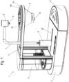
- eine Ansicht einer erfindungsgemäßen Maschine zur Zubereitung eines Heißgetränkes, und
Figur 2- eine Schnittansicht durch den Filterhalter der Maschine der
Figur 1 .
- Figure 1
- a view of a machine according to the invention for preparing a hot drink, and
- Figure 2
- a sectional view through the filter holder of the machine
Figure 1 .
Eine Maschine 1 zur Zubereitung eines Heißgetränkes umfasst eine Basisstation 2, die ein Gehäuse aufweist, in dem eine Heizeinrichtung, eine Pumpe und eine Steuerung angeordnet sind. An der Basisstation 2 ist ein abnehmbarer Tank 3 für Frischwasser vorgesehen, über den Wasser zu der Pumpe, der Heizeinrichtung und zu einem Zulauf 7 förderbar ist. Der Zulauf 7 ist als Rohrleitung ausgebildet, die von der Basisstation 2 nach oben hervorsteht. Dabei ist der Zulauf 7 nicht stationär an dem Gehäuse der Basisstation 2 angeordnet, sondern über eine Antriebseinrichtung bewegbar. Hierfür ist ein Schlitten 6 vorgesehen, der durch die Antriebseinrichtung entlang einer Führung unterhalb einer Gehäuseöffnung 25 an der Basisstation 2 linear bewegbar ist. Zudem kann der Schlitten 6 über einen weiteren Antrieb gedreht werden, so dass der Zulauf 7 um eine vertikale Achse drehbar ist. Es können auch andere Antriebe zum Bewegen des Zulaufes 7 eingesetzt werden.A machine 1 for preparing a hot drink includes a
Der Zulauf 7 weist einen vertikalen Abschnitt und einen horizontalen Abschnitt auf, wobei der Zulauf 7 an einem Auslass 9 mündet, der oberhalb eines Filterhalters 10 angeordnet ist. An dem Zulauf 7 ist oberhalb des Auslasses 9 ferner ein Halter 8 vorgesehen, an dem beispielsweise ein Leuchtmittel, insbesondere LED-Leuchtmittel, vorgesehen ist, das über eine Steuerung in der Basisstation 2 ansteuerbar ist. Zudem kann an dem Halter 8 ein optischer Sensor vorgesehen sein, der erfasst, ob ein Filterhalter 10 an einer Haltevorrichtung 4 der Maschine 1 eingesetzt ist oder nicht. Optional kann ein solcher Sensor auch feststellen, ob in dem Filterhalter 10 ein Filterpapiereinsatz und/oder ein Extraktionsmaterial angeordnet ist. Hierfür kann beispielsweise ein optischer Sensor mit entsprechender Farberkennung eingesetzt werden.The
Die Maschine weist an der Basisstation 2 eine feststehende Haltevorrichtung 4 auf, an der eine schalenförmige Halterung 5 zum lösbaren Einsetzen des Filterhalters 10 vorgesehen ist. An der Unterseite der Halterung 5 ist ein Auslass 12 für das Brühgetränk vorgesehen, insbesondere für Kaffee oder Tee.The machine has a fixed holding device 4 at the
Der Filterhalter 10 ist in
Der Filterhalter 10 umfasst eine nach oben offene Aufnahme 13 an einem ersten Teil 16. In die Aufnahme 13 kann ein Filterpapiereinsatz oder ein anderer Filtereinsatz mit einem Extraktionsmaterial eingefügt werden. An der Unterseite der Aufnahme 13 ist an einem Boden ein Ventil 14 vorgesehen, mittels dem eine untere Auslassöffnung an dem Teil 16 geöffnet und geschlossen werden kann. Das Ventil 14 ist dabei in die geschlossene Position vorgespannt und kann wahlweise über mechanische Betätigungsmittel, beispielsweise ein Gefäß unterhalb des Filterhalters 10, das Einsetzen in den Halter 5 und Interaktion mit einer Betätigungsgeometrie 15 oder durch eine Steuerung geöffnet oder geschlossen werden. Bei geöffnetem Ventil 14 kann das gebrühte Getränk durch den Auslass 12 in ein Gefäß abgegeben werden.The
Um das erste Teil 16 des Filterhalters 10 ist ein zweites Teil 17 angeordnet, das ebenfalls schalenförmig ausgebildet ist und in einem Abstand zu dem ersten Teil 16 angeordnet ist. Dadurch ist zwischen dem ersten Teil 16 und dem zweiten Teil 17 eine ringförmige oder hülsenförmige Kammer 21 zum Sammeln von Wasser ausgebildet. Das erste Teil 16 und das zweite Teil 17 sind in einem unteren Bereich über mindestens ein Dichtelement 20 dichtend aneinander angeordnet.A
Der Filterhalter 10 ist in die ring- oder schalenförmige Halterung 5 der Maschine 1 lösbar eingesetzt und kann über einen hervorstehenden Griffabschnitt 23 auf einfache Weise nach oben entnommen werden.The
An dem Filterhalter 10 ist eine nach oben weisende Öffnung 19 ausgebildet, in die eine erste Menge an Wasser einfüllbar ist. Unterhalb der Öffnung 19 ist eine Aufprallfläche 22 vorgesehen, die integral mit dem zweiten Teil 17 unterhalb eines horizontalen Randes 18 des Filterhalters 10 angeordnet ist. Die Aufprallfläche 22 ist zur Horizontalen geneigt, beispielsweise in einem Winkel zwischen 10° und 60°, insbesondere 30° bis 55°, um auftreffendes Wasser in die Kammer 21 abzuleiten, ohne dass der Rand 18, andere Bauteile oder im schlimmsten Fall der Nutzer mit heißem Wasser bespritzt werden.An upward-pointing
Die ringförmige Kammer 21 zwischen dem ersten Teil 16 und dem zweiten Teil 17 weist vorzugsweise ein Volumen zwischen 10 ml bis 400 ml, insbesondere 20 ml bis 80 ml, auf.The annular chamber 21 between the
Zum Brühen von Kaffee wird zunächst in den Filterhalter 10 ein Filterpapiereinsatz mit einem Extraktionsmaterial eingesetzt. Der Filterpapiereinsatz kann dabei wahlweise nach oben offen ausgestaltet sein oder geschlossen, um dann erst über das Aufbringen von heißem Wasser eine Öffnung zu bewirken, wie dies beispielsweise in der
Optional kann dann über einen Sensor erfasst werden, ob der Filterhalter 10 mit Extraktionsmaterial oder einer Portionspackung befüllt ist. Hierfür kann ein Leuchtmittel an dem Halter 8 den Filterhalter 10 entsprechend beleuchten, um dann mit einem optischen Sensor eine Erfassung durchzuführen, die an eine Steuerung in der Basisstation 2 weitergeleitet wird.Optionally, a sensor can then be used to detect whether the
Die Maschine 1 saugt nun Wasser aus dem Tank 3 an und fördert dies über eine Pumpe und eine Heizeinrichtung in den Zulauf 7, der in einer ersten Position mit dem Auslass 9 oberhalb der Öffnung 19 angeordnet ist. Dadurch wird eine erste Menge an Wasser in die Öffnung 19 und somit die Kammer 21 zum Sammeln von Wasser eingeleitet. Die erste Menge an Wasser kann beispielsweise zwischen 5 ml und 30 ml betragen und reicht aus, um den Zulauf 7 vorzuwärmen und zu spülen.The machine 1 now sucks water from the
Nach dem Einleiten einer ersten Menge an Wasser in die Kammer 21 wird der Zulauf 7 relativ zu dem Filterhalter 10 bewegt, wobei in diesem Ausführungsbeispiel der Filterhalter 10 stationär angeordnet ist und der Zulauf 7 über einen oder mehrere Antriebe bewegt wird. Dann kann nun heißes Wasser aus dem Zulauf 7 entweder direkt auf das Extraktionsmaterial oder eine Verschlussvorrichtung an einer Portionspackung aufgegeben werden, um den Brühvorgang zu beginnen. Optional kann das heiße Wasser aus dem Zulauf 7 auch über das Extraktionsmaterial verteilt werden entsprechend vorgegebenen Mustern, so dass eine gleichmäßigere Extraktion möglich ist. Der Zulauf 7 kann somit auch während des Ausgebens einer zweiten Menge an heißem Wasser bewegt werden. Das Brühgetränk, insbesondere der Kaffee, wird nun an dem Auslass 12 in ein nicht dargestelltes Gefäß ausgegeben. Das Gefäß ist dabei auf dem Tassenblech einer Tropfschale 11 abgestellt. Dabei ist das Tassenblech mit Öffnungen versehen, so dass nach der Entnahme des Gefäßes Tropfen des Brühgetränkes in der Tropfschale 11 gesammelt werden können. Nach dem Brühen kann dann der Filterhalter 10 aus der Halterung 5 entnommen werden, um sowohl das gebrühte Extraktionsmaterial zu entsorgen als auch das gesammelte Wasser aus der Kammer 21 zu entleeren.After introducing a first amount of water into the chamber 21, the
An dem Filterhalter 10 ist bezogen auf die Aufnahme 13 eine zweite Öffnung 19' gegenüberliegend zu der ersten Öffnung 19 angeordnet. Dadurch kann der Filterhalter 10 auch um 180° gedreht eingesetzt werden, um über die zweite Öffnung 19' Wasser in der Kammer 21 zu sammeln.On the
In dem dargestellten Ausführungsbeispiel ist die Kammer 21 ringförmig zwischen dem ersten Teil 16 und dem zweiten Teil 17 angeordnet. Es ist natürlich auch möglich, die Kammer 21 nur an einer Seite des Filterhalters vorzusehen, und nicht ringförmig zu gestalten.In the exemplary embodiment shown, the chamber 21 is arranged in a ring shape between the
- 11
- Maschinemachine
- 22
- BasisstationBase station
- 33
- Tanktank
- 44
- HaltevorrichtungHolding device
- 55
- Halterungbracket
- 66
- SchlittenSleds
- 77
- ZulaufIntake
- 88th
- Halterholder
- 99
- Auslassoutlet
- 1010
- FilterhalterFilter holder
- 1111
- TropfschaleDrip tray
- 1212
- Auslassoutlet
- 1313
- AufnahmeRecording
- 1414
- VentilValve
- 1515
- BetätigungsgeometrieActuation geometry
- 1616
- erstes Teilfirst part
- 1717
- zweites Teilsecond part
- 1818
- Randedge
- 1919
- Öffnungopening
- 19'19'
- Öffnungopening
- 2020
- DichtelementSealing element
- 2121
- Kammerchamber
- 2222
- AufprallflächeImpact surface
- 2323
- GriffabschnittHandle section
- 2525
- GehäuseöffnungCase opening
Claims (13)
- Machine (1) for the preparation of a hot beverage, comprising- a device for the production and delivery of hot water;- a holding device (4) into which a filter holder (10) can be detachably inserted;- a feed (7) for the hot water having an outlet (9) arranged above the filter holder (10) for discharging the hot water from above the filter holder (10) into an upwardly open receptacle (13) containing an extraction material, and- a drive device to move the feed (7) for the hot water relative to the filter holder (10),characterized in that the filter holder (10) comprises a chamber (21) for water which is fillable via an opening (19, 19') and the feed (7) is movable relative to the filter holder (10) between a position substantially vertically above the opening (19) and a further position substantially vertically above the receptacle (13) with the extraction material.
- Machine according to claim 1, characterized in that the chamber (21) for collecting water in the filter holder (10) has a volume between 10 ml to 400 ml, in particular 20 ml to 80 ml.
- Machine according to claim 1 or 2, characterized in that the filter holder (10) is formed in several parts and a first part (16) forms a receptacle for the extraction material and the first part (16) is surrounded by a second part (17) at least in regions, and the chamber (21) for collecting water is formed between the first part (16) and the second part (17).
- Machine according to claim 3, characterized in that the chamber (21) is of annular design and a sealing element (20) is arranged between the first part (16) and the second part (17).
- Machine according to claim 3 or 4, characterized in that the second part (17) is fixed to the first part (16) by fastening means.
- Machine according to one of the preceding claims, characterized in that an impact surface (22) inclined to the horizontal is provided at the opening (19, 19'), from which the applied hot water drains into the chamber (21).
- Machine according to one of the preceding claims, characterized in that on the filter holder (10) the receptacle (13) is arranged between a first opening (19) and a second opening (19') connected to the chamber (21) for collecting water.
- Machine according to one of the preceding claims, characterized in that a valve (14) for opening or closing an outlet opening is provided on the receptacle (13) on the underside.
- Machine according to one of the preceding claims, characterized in that a sensor is provided on the feed (7) or the holding device (4), by means of which it can be detected whether the filter holder (10) is arranged on the holding device (4).
- Machine according to one of the preceding claims, characterized in that a downwardly radiating light source is provided at the feed (7).
- Method for preparing a hot beverage, comprising the steps of:- heating water and conveying the heated water to a feed (7);- dispensing a first amount of water at the feed (7) into an opening (19, 19') on a filter holder (10) from which the first amount of water is directed into a chamber (21) for collecting the water;- moving the feed (7) relative to the filter holder (10) to move the feed (7) from a position above the opening (19, 19') to a position above an upwardly open receptacle (13) containing an extraction material, and- dispensing a second amount of hot water onto the extraction material in the filter holder (10) to brew the hot beverage.
- Method according to claim 11, characterized in that the first amount of hot water is between 1 ml to 80 ml, in particular between 5 ml to 30 ml.
- Method according to claim 11 or 12, characterized in that the filter holder (10) is arranged stationary and the feed (7) is moved via a drive device.
Applications Claiming Priority (2)
| Application Number | Priority Date | Filing Date | Title |
|---|---|---|---|
| DE102020101086.9A DE102020101086A1 (en) | 2020-01-17 | 2020-01-17 | Machine and method for preparing a hot beverage |
| PCT/EP2020/085781 WO2021144089A1 (en) | 2020-01-17 | 2020-12-11 | Machine and method for preparing a hot beverage |
Publications (2)
| Publication Number | Publication Date |
|---|---|
| EP4090202A1 EP4090202A1 (en) | 2022-11-23 |
| EP4090202B1 true EP4090202B1 (en) | 2023-09-20 |
Family
ID=74095791
Family Applications (1)
| Application Number | Title | Priority Date | Filing Date |
|---|---|---|---|
| EP20829827.3A Active EP4090202B1 (en) | 2020-01-17 | 2020-12-11 | Machine and method for preparing a hot beverage |
Country Status (7)
| Country | Link |
|---|---|
| US (1) | US20230034000A1 (en) |
| EP (1) | EP4090202B1 (en) |
| JP (1) | JP2023512614A (en) |
| DE (1) | DE102020101086A1 (en) |
| DK (1) | DK4090202T3 (en) |
| FI (1) | FI4090202T3 (en) |
| WO (1) | WO2021144089A1 (en) |
Families Citing this family (2)
| Publication number | Priority date | Publication date | Assignee | Title |
|---|---|---|---|---|
| DE102021132207A1 (en) * | 2021-12-07 | 2023-06-07 | Melitta Single Portions Gmbh & Co. Kg | Machine and method for preparing a brewed beverage |
| USD1005035S1 (en) * | 2021-12-23 | 2023-11-21 | Balmuda Inc. | Coffee maker |
Family Cites Families (7)
| Publication number | Priority date | Publication date | Assignee | Title |
|---|---|---|---|---|
| DE7735174U1 (en) * | 1977-11-16 | 1979-04-26 | Bosch-Siemens Hausgeraete Gmbh, 7000 Stuttgart | Electric coffee maker |
| DE19920581A1 (en) * | 1999-05-04 | 2000-11-16 | Franzius Kristian | Device for putting hot water into hot drinks heats up water from a reservoir container in a pipe with heating integrated feeding into a coffee filter. |
| DE20119704U1 (en) * | 2001-12-05 | 2002-02-21 | Cloer Elektrogeraete Gmbh | Electrically operated device for preparing hot infusion drinks |
| US8539876B2 (en) | 2010-02-02 | 2013-09-24 | Newco Enterprises, Inc. | Brew basket with integrated separate cavity for water bypass or additives |
| CN103313634B (en) | 2010-12-28 | 2016-10-26 | 星巴克公司,贸易用名星巴克咖啡公司 | Equipment and correlation technique for beverage brewed |
| DE202012103158U1 (en) | 2012-08-21 | 2013-11-25 | Melitta Europa Gmbh & Co. Kg | coffee machine |
| DE102018101333A1 (en) | 2018-01-22 | 2019-07-25 | Melitta Single Portions Gmbh & Co. Kg | Portion pack and method of making a beverage |
-
2020
- 2020-01-17 DE DE102020101086.9A patent/DE102020101086A1/en active Pending
- 2020-12-11 US US17/791,313 patent/US20230034000A1/en active Pending
- 2020-12-11 DK DK20829827.3T patent/DK4090202T3/en active
- 2020-12-11 FI FIEP20829827.3T patent/FI4090202T3/en active
- 2020-12-11 WO PCT/EP2020/085781 patent/WO2021144089A1/en unknown
- 2020-12-11 JP JP2022543595A patent/JP2023512614A/en active Pending
- 2020-12-11 EP EP20829827.3A patent/EP4090202B1/en active Active
Also Published As
| Publication number | Publication date |
|---|---|
| US20230034000A1 (en) | 2023-02-02 |
| DE102020101086A1 (en) | 2021-07-22 |
| DK4090202T3 (en) | 2023-12-11 |
| WO2021144089A1 (en) | 2021-07-22 |
| CN114929076A (en) | 2022-08-19 |
| FI4090202T3 (en) | 2023-12-04 |
| EP4090202A1 (en) | 2022-11-23 |
| JP2023512614A (en) | 2023-03-28 |
Similar Documents
| Publication | Publication Date | Title |
|---|---|---|
| EP3166451B1 (en) | Apparatus and method for preparing a brewed beverage | |
| EP3166452B1 (en) | Apparatus and method for preparing a brewed beverage | |
| EP4090202B1 (en) | Machine and method for preparing a hot beverage | |
| DE60129486T2 (en) | Apparatus for applying and heating liquids, in particular milk | |
| EP1817991B1 (en) | Hot drinks machine | |
| DE102008007254A1 (en) | Container, in particular coffee mug, and apparatus and method for preparing liquid food, in particular coffee, for a vehicle | |
| DE102010004730A1 (en) | Milk frothing unit according to the circulation principle | |
| EP0292649A1 (en) | Domestic apparatus for making tea | |
| EP3166450B1 (en) | Method and apparatus for preparing a brewed beverage | |
| EP1878369B1 (en) | Device for heating a drinking vessel | |
| WO1981001951A1 (en) | Device for the preparation of hot beverages and method for its operation | |
| DE2421620A1 (en) | DEVICE FOR INDEPENDENT BEVERAGE PRODUCTION | |
| EP3873306A1 (en) | Machine for preparing hot beverages | |
| EP1804629A2 (en) | Coffee machine with a pouring vessel | |
| EP3727107B1 (en) | Device and method for producing a brewed beverage | |
| WO2021144469A1 (en) | Percolator-type device for preparing hot drinks, especially coffee and/or tea | |
| DE102010004727B4 (en) | Device according to the riser principle for the preparation of a hot beverage | |
| EP3838076B1 (en) | Device and method for producing a brewed beverage | |
| EP3838075B1 (en) | Device for preparing a brewed drink | |
| DE102014019878B3 (en) | Device and method for preparing a brewed beverage | |
| DE2740249A1 (en) | COFFEE MACHINE | |
| EP3838077A1 (en) | Device for preparing a brewed beverage | |
| DE3207046C2 (en) |
Legal Events
| Date | Code | Title | Description |
|---|---|---|---|
| STAA | Information on the status of an ep patent application or granted ep patent |
Free format text: STATUS: UNKNOWN |
|
| STAA | Information on the status of an ep patent application or granted ep patent |
Free format text: STATUS: THE INTERNATIONAL PUBLICATION HAS BEEN MADE |
|
| PUAI | Public reference made under article 153(3) epc to a published international application that has entered the european phase |
Free format text: ORIGINAL CODE: 0009012 |
|
| STAA | Information on the status of an ep patent application or granted ep patent |
Free format text: STATUS: REQUEST FOR EXAMINATION WAS MADE |
|
| 17P | Request for examination filed |
Effective date: 20220713 |
|
| AK | Designated contracting states |
Kind code of ref document: A1 Designated state(s): AL AT BE BG CH CY CZ DE DK EE ES FI FR GB GR HR HU IE IS IT LI LT LU LV MC MK MT NL NO PL PT RO RS SE SI SK SM TR |
|
| DAV | Request for validation of the european patent (deleted) | ||
| DAX | Request for extension of the european patent (deleted) | ||
| GRAP | Despatch of communication of intention to grant a patent |
Free format text: ORIGINAL CODE: EPIDOSNIGR1 |
|
| STAA | Information on the status of an ep patent application or granted ep patent |
Free format text: STATUS: GRANT OF PATENT IS INTENDED |
|
| INTG | Intention to grant announced |
Effective date: 20230517 |
|
| P01 | Opt-out of the competence of the unified patent court (upc) registered |
Effective date: 20230704 |
|
| GRAS | Grant fee paid |
Free format text: ORIGINAL CODE: EPIDOSNIGR3 |
|
| GRAA | (expected) grant |
Free format text: ORIGINAL CODE: 0009210 |
|
| STAA | Information on the status of an ep patent application or granted ep patent |
Free format text: STATUS: THE PATENT HAS BEEN GRANTED |
|
| AK | Designated contracting states |
Kind code of ref document: B1 Designated state(s): AL AT BE BG CH CY CZ DE DK EE ES FI FR GB GR HR HU IE IS IT LI LT LU LV MC MK MT NL NO PL PT RO RS SE SI SK SM TR |
|
| REG | Reference to a national code |
Ref country code: GB Ref legal event code: FG4D Free format text: NOT ENGLISH |
|
| REG | Reference to a national code |
Ref country code: CH Ref legal event code: EP |
|
| REG | Reference to a national code |
Ref country code: DE Ref legal event code: R096 Ref document number: 502020005344 Country of ref document: DE |
|
| REG | Reference to a national code |
Ref country code: IE Ref legal event code: FG4D Free format text: LANGUAGE OF EP DOCUMENT: GERMAN |
|
| REG | Reference to a national code |
Ref country code: NL Ref legal event code: FP |
|
| REG | Reference to a national code |
Ref country code: NO Ref legal event code: T2 Effective date: 20230920 |
|
| REG | Reference to a national code |
Ref country code: DK Ref legal event code: T3 Effective date: 20231205 |
|
| REG | Reference to a national code |
Ref country code: SE Ref legal event code: TRGR |
|
| REG | Reference to a national code |
Ref country code: LT Ref legal event code: MG9D |
|
| PG25 | Lapsed in a contracting state [announced via postgrant information from national office to epo] |
Ref country code: GR Free format text: LAPSE BECAUSE OF FAILURE TO SUBMIT A TRANSLATION OF THE DESCRIPTION OR TO PAY THE FEE WITHIN THE PRESCRIBED TIME-LIMIT Effective date: 20231221 |
|
| PG25 | Lapsed in a contracting state [announced via postgrant information from national office to epo] |
Ref country code: RS Free format text: LAPSE BECAUSE OF FAILURE TO SUBMIT A TRANSLATION OF THE DESCRIPTION OR TO PAY THE FEE WITHIN THE PRESCRIBED TIME-LIMIT Effective date: 20230920 Ref country code: LV Free format text: LAPSE BECAUSE OF FAILURE TO SUBMIT A TRANSLATION OF THE DESCRIPTION OR TO PAY THE FEE WITHIN THE PRESCRIBED TIME-LIMIT Effective date: 20230920 Ref country code: LT Free format text: LAPSE BECAUSE OF FAILURE TO SUBMIT A TRANSLATION OF THE DESCRIPTION OR TO PAY THE FEE WITHIN THE PRESCRIBED TIME-LIMIT Effective date: 20230920 Ref country code: HR Free format text: LAPSE BECAUSE OF FAILURE TO SUBMIT A TRANSLATION OF THE DESCRIPTION OR TO PAY THE FEE WITHIN THE PRESCRIBED TIME-LIMIT Effective date: 20230920 Ref country code: GR Free format text: LAPSE BECAUSE OF FAILURE TO SUBMIT A TRANSLATION OF THE DESCRIPTION OR TO PAY THE FEE WITHIN THE PRESCRIBED TIME-LIMIT Effective date: 20231221 |
|
| PGFP | Annual fee paid to national office [announced via postgrant information from national office to epo] |
Ref country code: SE Payment date: 20231220 Year of fee payment: 4 Ref country code: NO Payment date: 20231222 Year of fee payment: 4 Ref country code: NL Payment date: 20231220 Year of fee payment: 4 Ref country code: LU Payment date: 20231220 Year of fee payment: 4 Ref country code: FR Payment date: 20231222 Year of fee payment: 4 Ref country code: FI Payment date: 20231221 Year of fee payment: 4 Ref country code: DK Payment date: 20231227 Year of fee payment: 4 Ref country code: DE Payment date: 20231231 Year of fee payment: 4 |
|
| PGFP | Annual fee paid to national office [announced via postgrant information from national office to epo] |
Ref country code: BE Payment date: 20231220 Year of fee payment: 4 |
|
| PG25 | Lapsed in a contracting state [announced via postgrant information from national office to epo] |
Ref country code: IS Free format text: LAPSE BECAUSE OF FAILURE TO SUBMIT A TRANSLATION OF THE DESCRIPTION OR TO PAY THE FEE WITHIN THE PRESCRIBED TIME-LIMIT Effective date: 20240120 |