EP4089709B1 - Betätigungsmechanismus eines elektromagnetischen reststromschutzschalters mit 2p2-modulus und überstromschutz - Google Patents
Betätigungsmechanismus eines elektromagnetischen reststromschutzschalters mit 2p2-modulus und überstromschutz Download PDFInfo
- Publication number
- EP4089709B1 EP4089709B1 EP21844625.0A EP21844625A EP4089709B1 EP 4089709 B1 EP4089709 B1 EP 4089709B1 EP 21844625 A EP21844625 A EP 21844625A EP 4089709 B1 EP4089709 B1 EP 4089709B1
- Authority
- EP
- European Patent Office
- Prior art keywords
- latch
- linked
- hinging
- linking shaft
- hinged
- Prior art date
- Legal status (The legal status is an assumption and is not a legal conclusion. Google has not performed a legal analysis and makes no representation as to the accuracy of the status listed.)
- Active
Links
Images


Classifications
-
- H—ELECTRICITY
- H01—ELECTRIC ELEMENTS
- H01H—ELECTRIC SWITCHES; RELAYS; SELECTORS; EMERGENCY PROTECTIVE DEVICES
- H01H71/00—Details of the protective switches or relays covered by groups H01H73/00 - H01H83/00
- H01H71/10—Operating or release mechanisms
- H01H71/50—Manual reset mechanisms which may be also used for manual release
- H01H71/52—Manual reset mechanisms which may be also used for manual release actuated by lever
- H01H71/526—Manual reset mechanisms which may be also used for manual release actuated by lever the lever forming a toggle linkage with a second lever, the free end of which is directly and releasably engageable with a contact structure
-
- H—ELECTRICITY
- H01—ELECTRIC ELEMENTS
- H01H—ELECTRIC SWITCHES; RELAYS; SELECTORS; EMERGENCY PROTECTIVE DEVICES
- H01H71/00—Details of the protective switches or relays covered by groups H01H73/00 - H01H83/00
- H01H71/10—Operating or release mechanisms
- H01H71/1009—Interconnected mechanisms
-
- H—ELECTRICITY
- H01—ELECTRIC ELEMENTS
- H01H—ELECTRIC SWITCHES; RELAYS; SELECTORS; EMERGENCY PROTECTIVE DEVICES
- H01H71/00—Details of the protective switches or relays covered by groups H01H73/00 - H01H83/00
- H01H71/10—Operating or release mechanisms
- H01H71/50—Manual reset mechanisms which may be also used for manual release
- H01H71/505—Latching devices between operating and release mechanism
- H01H2071/508—Latching devices between operating and release mechanism with serial latches, e.g. primary latch latched by secondary latch for requiring a smaller trip force
Definitions
- the present invention relates to the technical field of circuit breakers, and more particularly, to an operation mechanism of a 2P2M electromagnetic residual current circuit breaker with overcurrent protection (RCBO).
- RCBO overcurrent protection
- RCBO also called earth leakage circuit breaker or ground fault circuit interrupter
- the RCBO is mainly used to protect a person in danger when current leakage occurs in a device, and may be used to protect a line or a motor to avoid overload or short circuit, or may be used in normal cases when a line is infrequently converted and started.
- the RCBO usually includes a housing.
- a circuit breaker apparatus and a current leakage protection apparatus are distributed in the housing.
- the circuit breaker apparatus is used to control connection or disconnection of a movable contact and a fixed contact when short circuit or overload occurs or a line is infrequently started.
- the current leakage protection apparatus is used to control the connection or disconnection of the movable contact and the fixed contact when current leakage occurs.
- the circuit breaker apparatus usually includes an operation mechanism, a thermal tripping mechanism, an electromagnetic tripping mechanism, and an arc extinguishing system.
- the operation mechanism includes a handle, a contact lever, and a latch.
- the connection or disconnection of the movable contact and the fixed contact may be controlled through a linkage structure among the handle, the contact lever, and the latch.
- the latch is used to link the current leakage protection apparatus to the operation mechanism, to control the connection or disconnection of the movable contact and the fixed contact when current leakage occurs.
- circuit breaker in the prior art has a large quantity of components.
- each circuit breaker is connected to one handle linkage mechanism for operation.
- handle linkage mechanisms Document CN 111 293 009 A discloses an operation mechanism according to the preamble of claim 1.
- the present invention provides an operation mechanism of a 2P2M electromagnetic RCBO in which a single handle may control multiple circuit breakers. This simplifies a structure and reduces the overall structural complicity of the circuit breaker and a quantity of components so that costs are reduced and processing and assembly are convenient.
- An operation mechanism of a 2P2M electromagnetic RCBO including a handle and a connection rod with one end linked to the handle, where the other end of the connection rod opposite to the end linked to the handle is linked to a contact lever; a first hinging and linking shaft with one end hinged to a housing of the circuit breaker is disposed in the middle part of the contact lever; a first latch hinged to one end of the first hinging and linking shaft is linked to one side of the contact lever; an end of the first latch intermittently abuts against and is linked to the contact lever, and a second latch hinged to the other end of the first hinging and linking shaft is linked to the other side of the contact lever opposite to the side linked to the first latch; the other end of the contact lever opposite to the end linked to the connection rod is provided with a second hinging and linking shaft; the side of the contact lever towards the first latch is linked to a first movable contact, where the first movable contact is hinged
- the structure of the operation mechanism is improved.
- the first latch and the second latch are respectively linked to the two sides of the contact lever through the two ends of the first hinging and linking shaft, and further the first movable contact and the second movable contact are respectively linked to the two sides of the contact lever through the two ends of the second hinging and linking shaft.
- one handle may drive two movable contacts, and further, a single handle may control multiple circuit breakers. This simplifies a structure of the operation mechanism and reduces the overall structural complicity of the circuit breaker and a quantity of components, so that costs are reduced and processing and assembly are convenient.
- a relative linkage structure is disposed between the first latch and the second latch.
- the foregoing operation mechanism of a 2P2M electromagnetic RCBO is further set as follows.
- the relative linkage structure includes an insertion pin disposed on a side of the middle part of the second latch towards the first latch; the first latch is provided with a linkage shaft hole that fits with the insertion pin; and the contact lever may be driven by the connection rod to push the first latch to rotate around the first hinging and linking shaft, and the second latch follows the first latch through the insertion pin to rotate around the first hinging and linking shaft.
- the first latch drives the second latch to work with the handle, so that a single handle may control multiple circuit breakers.
- the two circuit breakers work highly simultaneously, security of the circuit breakers is enhanced.
- the foregoing operation mechanism of a 2P2M electromagnetic RCBO is further set as follows.
- a side of the middle part of the second latch far away from the first latch is provided with a first push pin linked to a current leakage protection apparatus.
- the first push pin is disposed, so that the current leakage protection apparatus is linked to the circuit breaker apparatus. Therefore, when current leakage occurs, the current leakage protection apparatus may control multiple circuit breakers by using the first push pin, to ensure that the current leakage protection apparatus works normally.
- the foregoing operation mechanism of a 2P2M electromagnetic RCBO may further be set as follows.
- a flexible connection mechanism is disposed between the connection rod and the contact lever.
- the foregoing operation mechanism of a 2P2M electromagnetic RCBO may further be set as follows.
- the flexible connection mechanism includes a flexible linkage block with one end hinged to an end of the connection rod, and the other end of the flexible linkage block opposite to the end linked to the connection rod is hinged to the contact lever.
- connection manner of the handle and the connection rod makes the connection rod move curvedly, and the flexible connection mechanism disposed between the connection rod and the contact lever makes the connection rod and the contact lever move more smoothly and free from getting stuck.
- the two ends of the flexible linkage block may perform adaptive motion under action of the connection rod and the contact lever, so that the two ends of the flexible linkage block may not get stuck.
- the foregoing operation mechanism of a 2P2M electromagnetic RCBO may further be set as follows. An end of the first movable contact adjacent to the second hinging and linking shaft and an end of the second movable contact adjacent to the second hinging and linking shaft are separately fixed to a second push pin intermittently linked to a thermal tripping mechanism in the circuit breaker.
- the second push pin is disposed, so that the thermal tripping mechanism in the circuit breaker may be linked to the operation mechanism.
- the thermal tripping mechanism may successively drive the two movable contacts to be separated from a fixed contact, to ensure that the thermal tripping mechanism works normally, thereby enhancing security of the circuit breaker.
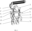
- An operation mechanism of a 2P2M electromagnetic RCBO shown in FIG. 1 to FIG. 7 includes a handle 1 and a connection rod 2 with one end linked to the handle 1.
- the other end of the connection rod 2 opposite to the end linked to the handle 1 is linked to a contact lever 3.
- a first hinging and linking shaft 4 with one end hinged to a housing of the circuit breaker is disposed in the middle part of the contact lever 3.
- a first latch 5 hinged to one end of the first hinging and linking shaft 4 is linked to one side of the contact lever 3.
- An end of the first latch 5 intermittently abuts against and is linked to the contact lever 3.
- a second latch 6 hinged to the other end of the first hinging and linking shaft 4 is linked to the other side of the contact lever 3 opposite to the side linked to the first latch 5.
- a relative linkage structure is disposed between the first latch 5 and the second latch 6.
- the other end of the contact lever 3 opposite to the end linked to the connection rod 2 is provided with a second hinging and linking shaft 7.
- the side of the contact lever 3 towards the first latch 5 is linked to a first movable contact 8, where the first movable contact 8 is hinged to an end of the second hinging and linking shaft 7 and may be intermittently linked to the first latch 5.
- a first reset spring 10 linked to the first movable contact 8 is sleeved on a position where the second hinging and linking shaft 7 is hinged to the first movable contact 8.
- the side of the contact lever 3 towards the second latch 6 is linked to a second movable contact 9, where the second movable contact 9 is hinged to the end of the second hinging and linking shaft 7 and may be intermittently linked to the second latch 6.
- a second reset spring 11 linked to the second movable contact 9 is sleeved on a position where the second hinging and linking shaft 7 is hinged to the second movable contact 9.
- the relative linkage structure includes an insertion pin 61 disposed on a side of the middle part of the second latch 6 towards the first latch 5.
- the first latch 5 is provided with a linkage shaft hole 51 that fits with the insertion pin 61.
- the contact lever 3 is driven by the connection rod 2 to push the first latch 5 to rotate around the first hinging and linking shaft 4.
- the second latch 6 follows the first latch 5 through the insertion pin 61 to rotate around the first hinging and linking shaft 4.
- One side of the middle part of the second latch 6 far away from the first latch 5 is provided with a first push pin 62 linked to a current leakage protection apparatus.
- a flexible connection mechanism is disposed between the connection rod 2 and the contact lever 3, and the flexible connection mechanism includes a flexible linkage block 12 with one end hinged to an end of the connection rod 2. The other end of the flexible linkage block 12 opposite to the end linked to the connection rod 2 is hinged to the contact lever 3.
- An end of the first movable contact adjacent to the second hinging and linking shaft 7 and an end of the second movable contact adjacent to the second hinging and linking shaft 7 are separately fixed to a second push pin 13 intermittently linked to a thermal tripping mechanism of the circuit breaker.
- the whole operation procedure is easy, in which one handle may drive two movable contacts, and further, a single handle may control multiple circuit breakers. This simplifies a structure of the operation mechanism and reduces the overall structural complicity of the circuit breaker and a quantity of components, so that costs are reduced and processing and assembly are convenient.
Landscapes
- Breakers (AREA)
- Driving Mechanisms And Operating Circuits Of Arc-Extinguishing High-Tension Switches (AREA)
Claims (4)
- Betätigungsmechanismus eines elektromagnetischen 2P2M-Fehlerstromschutzschalters mit Überstromschutz (RCBO), der einen Griff (1) und eine Verbindungsstange (2), von der ein Ende mit dem Griff (1) gekuppelt ist, umfasst, wobei das andere Ende der Verbindungsstange (2), dem Ende, das mit dem Griff (1) gekuppelt ist, entgegengesetzt, mit einem Kontakthebel (3) gekuppelt ist; eine erste Scharnier- und Kupplungswelle (4), von der ein Ende dazu konfiguriert ist, mit einem Gehäuse des Schutzschalters angelenkt zu sein, in einem Mittenteil des Kontakthebels (3) angeordnet ist; ein erster Riegel (5), der an einem Ende der ersten Scharnier- und Kupplungswelle (4) angelenkt ist, mit einer Seite des Kontakthebels (3) gekuppelt ist; ein Ende des ersten Riegels (5) intermittierend gegen den Kontakthebel (3) anliegt und damit gekuppelt ist, und ein zweiter Riegel (6), der an dem anderen Ende der ersten Scharnier- und Kupplungswelle (4) angelenkt ist, mit der anderen Seite des Kontakthebels (3), der Seite entgegengesetzt, die mit dem ersten Riegel (5) gekuppelt ist, gekuppelt ist; das andere Ende des Kontakthebels (3), das dem Ende, das mit der Verbindungsstange (2) gekuppelt ist, entgegengesetzt ist, mit einer zweiten Scharnier- und Kupplungswelle (7) versehen ist; die Seite des Kontakthebels (3) in Richtung des ersten Riegels (5) mit einem ersten bewegbaren Kontakthebel (8) gekuppelt ist, wobei der erste bewegbare Kontakthebel (8) an ein Ende der zweiten Scharnier- und Kupplungswelle (7) angelenkt und intermittierend mit dem ersten Riegel (5) gekuppelt ist; eine erste Rückstellfeder (10), die mit dem ersten bewegbaren Kontakthebel (8) gekuppelt ist, auf einer Position aufgehülst ist, an der die zweite Scharnier- und Kupplungswelle (7) an dem ersten bewegbaren KontakthfHülstebel (8) angelenkt ist; die Seite des Kontakthebels (3) in Richtung des zweiten Riegels (6) mit einem zweiten bewegbaren Kontakthebel (9) gekuppelt ist, wobei der zweite bewegbare Kontakthebel (9) an das Ende der zweiten Scharnier- und Kupplungswelle (7) angelenkt ist und intermittierend mit dem zweiten Riegel (6) gekuppelt ist; eine zweite Rückstellfeder (11), die mit dem zweiten bewegbaren Kontakthebel (9) gekuppelt ist, an einer Position aufgehülst ist, an der die zweite Scharnier- und Kupplungswelle (7) an dem zweiten bewegbaren Kontakthebel (9) angelenkt ist; und eine relative Kupplungsstruktur zwischen den ersten Riegel (5) und dem zweiten Riegel (6) angeordnet ist, und dadurch gekennzeichnet, dassdie relative Kupplungsstruktur einen Einfügestift (61) umfasst, der an einer Seite des Mittenteils des zweiten Riegels (6) in Richtung das ersten Riegels (5) angeordnet ist; der erste Riegel (5) mit einem Kupplungswellenloch (51) versehen ist, das mit dem Einfügestift (61) zusammenpasst; und der Kontakthebel (3) von der Verbindungsstange (2) angetrieben ist, um den ersten Riegel (5) zum Drehen um die erste Scharnier- und Kupplungswelle (4) zu schieben, und der zweite Riegel (6) dem ersten Riegel (5) durch den Einfügestift (61) folgt, um sich um die erste Scharnier- und Kupplungswelle (4) zu drehen,wobei eine Seite des Mittenteils des zweiten Riegels (6), die weit von dem ersten Riegel (5) entfernt ist, mit einem ersten Schubstift (62) versehen ist, der mit einem Fehlerstromschutzgerät gekuppelt ist.
- Betätigungsmechanismus des elektromagnetischen 2P2M-RCBO nach Anspruch 1, wobei ein flexibler Verbindungsmechanismus zwischen der Verbindungsstange (2) und dem Kontakthebel (3) angeordnet ist.
- Betätigungsmechanismus des elektromagnetischen 2P2M-RCBO nach Anspruch 2, wobei der flexible Verbindungsmechanismus einen flexiblen Kupplungsblock (12) umfasst, von dem ein Ende an einem Ende der Verbindungsstange (2) angelenkt ist, und das andere Ende des flexiblen Kupplungsblocks (12), das dem mit der Verbindungsstange (2) gekuppelten Ende entgegengesetzt ist, an dem Kontakthebel (3) angelenkt ist.
- Betätigungsmechanismus des elektromagnetischen 2P2M-RCBO nach Anspruch 1, wobei ein Ende des ersten bewegbaren Kontakts (8), das an die zweite Scharnier- und Kupplungswelle (7) angrenzt, und ein Ende des zweiten bewegbaren Kontakthebel (9), das an die zweite Scharnier- und Kupplungswelle (7) angrenzt, separat an einem zweiten Schubstift (13) befestigt sind, der intermittierend mit einem thermischen Auslösemechanismus in dem Schutzschalter gekuppelt ist.
Applications Claiming Priority (2)
| Application Number | Priority Date | Filing Date | Title |
|---|---|---|---|
| CN202110350635.4A CN112967912A (zh) | 2021-03-31 | 2021-03-31 | 一种2p2模数电磁式漏电保护断路器的操作机构 |
| PCT/CN2021/114977 WO2022205757A1 (zh) | 2021-03-31 | 2021-08-27 | 一种2p2模数电磁式漏电保护断路器的操作机构 |
Publications (4)
| Publication Number | Publication Date |
|---|---|
| EP4089709A1 EP4089709A1 (de) | 2022-11-16 |
| EP4089709A4 EP4089709A4 (de) | 2023-10-18 |
| EP4089709C0 EP4089709C0 (de) | 2024-07-31 |
| EP4089709B1 true EP4089709B1 (de) | 2024-07-31 |
Family
ID=76280660
Family Applications (1)
| Application Number | Title | Priority Date | Filing Date |
|---|---|---|---|
| EP21844625.0A Active EP4089709B1 (de) | 2021-03-31 | 2021-08-27 | Betätigungsmechanismus eines elektromagnetischen reststromschutzschalters mit 2p2-modulus und überstromschutz |
Country Status (3)
| Country | Link |
|---|---|
| EP (1) | EP4089709B1 (de) |
| CN (1) | CN112967912A (de) |
| WO (1) | WO2022205757A1 (de) |
Families Citing this family (2)
| Publication number | Priority date | Publication date | Assignee | Title |
|---|---|---|---|---|
| CN112967912A (zh) * | 2021-03-31 | 2021-06-15 | 英特曼电工(常州)有限公司 | 一种2p2模数电磁式漏电保护断路器的操作机构 |
| GB2644353A (en) * | 2024-09-30 | 2026-04-01 | Eaton Intelligent Power Ltd | Operating mechanism for a circuit breaker |
Family Cites Families (11)
| Publication number | Priority date | Publication date | Assignee | Title |
|---|---|---|---|---|
| US6614334B1 (en) * | 2002-06-27 | 2003-09-02 | Eaton Corporation | Circuit breaker including two circuit breaker mechanisms and an operating handle |
| CN202434448U (zh) * | 2012-01-06 | 2012-09-12 | 浙江鼎威科技有限公司 | 小体积的1p+n漏电断路器 |
| CN204179039U (zh) * | 2014-11-06 | 2015-02-25 | 张森林 | 断路器的四连杆机构 |
| CN205140895U (zh) * | 2015-09-22 | 2016-04-06 | 浙江正泰电器股份有限公司 | 断路器 |
| CN106783423B (zh) * | 2017-01-13 | 2018-08-07 | 乐清市也为电气有限公司 | 一种电气开关的操作机构 |
| CN208157335U (zh) * | 2018-05-03 | 2018-11-27 | 首瑞(天津)电气设备有限公司 | 一种断路器的操作机构和断路器 |
| CN111293009A (zh) * | 2020-03-27 | 2020-06-16 | 北京明日电器设备有限责任公司 | 一种单相双极小型漏电断路器的动作机构 |
| CN212365897U (zh) * | 2020-07-24 | 2021-01-15 | 上海良信电器股份有限公司 | 一种脱扣机构以及断路器 |
| CN112967912A (zh) * | 2021-03-31 | 2021-06-15 | 英特曼电工(常州)有限公司 | 一种2p2模数电磁式漏电保护断路器的操作机构 |
| CN112951665A (zh) * | 2021-03-31 | 2021-06-11 | 英特曼电工(常州)有限公司 | 一种2p2模数电磁式漏电保护断路器 |
| CN214542094U (zh) * | 2021-03-31 | 2021-10-29 | 英特曼电工(常州)有限公司 | 一种2p2模数电磁式漏电保护断路器的操作机构 |
-
2021
- 2021-03-31 CN CN202110350635.4A patent/CN112967912A/zh active Pending
- 2021-08-27 WO PCT/CN2021/114977 patent/WO2022205757A1/zh not_active Ceased
- 2021-08-27 EP EP21844625.0A patent/EP4089709B1/de active Active
Also Published As
| Publication number | Publication date |
|---|---|
| WO2022205757A1 (zh) | 2022-10-06 |
| EP4089709C0 (de) | 2024-07-31 |
| EP4089709A1 (de) | 2022-11-16 |
| CN112967912A (zh) | 2021-06-15 |
| EP4089709A4 (de) | 2023-10-18 |
Similar Documents
| Publication | Publication Date | Title |
|---|---|---|
| EP4089707B1 (de) | 2p2m elektromagnetischer fehlerstrom leistungsschalter mit überstrom schutz | |
| EP2277187B1 (de) | Elektrisches schaltgerät mit spannmechanismus und entsprechender verriegelung dazu | |
| EP4089709B1 (de) | Betätigungsmechanismus eines elektromagnetischen reststromschutzschalters mit 2p2-modulus und überstromschutz | |
| WO2008049336A1 (en) | Circuit breaker for rapidly breaking low voltage circuit | |
| EP4173019B1 (de) | Fehlerstrom-reststrom-anzeigemechanismus und schutzschalter mit fehlerstrom-anzeigemechanismus | |
| CN101170034A (zh) | 小型断路器 | |
| KR20250127068A (ko) | 하이브리드 회로 차단기에서 사용되는 초고속 액츄에이터를 위한 다부품 이동 샤프트 어셈블리 | |
| EP0632478A1 (de) | Elektrischer Schalteinrichtung mit Vorrichtung um verschweisste Kontakte aufzubrechen | |
| JP4454823B2 (ja) | 回路遮断器用の制御機構 | |
| EP1529299B1 (de) | Antriebsvorrichtung und verfahren zum betrieb einer schaltanordnung | |
| CN219759495U (zh) | 防撞型智能弹操断路器 | |
| EP4089708B1 (de) | Mehrfach verbindender betätigungshebel für schutzschalter | |
| CN214542094U (zh) | 一种2p2模数电磁式漏电保护断路器的操作机构 | |
| CN115602502B (zh) | 断路器脱扣结构 | |
| CN215069826U (zh) | 一种2p2模数电磁式漏电保护断路器 | |
| CN117116717A (zh) | 一种带漏电保护的断路器 | |
| CN213025989U (zh) | 断路器用漏电显示机构 | |
| CN212113603U (zh) | 一种脱扣机构及其采用该机构的微型断路器 | |
| CN210778385U (zh) | 负荷开关-熔断器组合电器 | |
| EP4089710B1 (de) | 2p2m fehlerstrom-schutzschalter mit elektromagnetischen überstrom schutz | |
| JP5217020B2 (ja) | 回路遮断器の開閉機構 | |
| CN223513884U (zh) | 操作系统、控制与保护开关 | |
| CN215869239U (zh) | 断路器脱扣结构 | |
| CN114709115B (zh) | 断路器旋转机构 | |
| CN214898300U (zh) | 一种断路器的动触头操作机构 |
Legal Events
| Date | Code | Title | Description |
|---|---|---|---|
| STAA | Information on the status of an ep patent application or granted ep patent |
Free format text: STATUS: UNKNOWN |
|
| STAA | Information on the status of an ep patent application or granted ep patent |
Free format text: STATUS: THE INTERNATIONAL PUBLICATION HAS BEEN MADE |
|
| PUAI | Public reference made under article 153(3) epc to a published international application that has entered the european phase |
Free format text: ORIGINAL CODE: 0009012 |
|
| STAA | Information on the status of an ep patent application or granted ep patent |
Free format text: STATUS: REQUEST FOR EXAMINATION WAS MADE |
|
| 17P | Request for examination filed |
Effective date: 20220127 |
|
| AK | Designated contracting states |
Kind code of ref document: A1 Designated state(s): AL AT BE BG CH CY CZ DE DK EE ES FI FR GB GR HR HU IE IS IT LI LT LU LV MC MK MT NL NO PL PT RO RS SE SI SK SM TR |
|
| A4 | Supplementary search report drawn up and despatched |
Effective date: 20230919 |
|
| RIC1 | Information provided on ipc code assigned before grant |
Ipc: H01H 71/52 20060101ALI20230913BHEP Ipc: H01H 71/10 20060101AFI20230913BHEP |
|
| GRAP | Despatch of communication of intention to grant a patent |
Free format text: ORIGINAL CODE: EPIDOSNIGR1 |
|
| STAA | Information on the status of an ep patent application or granted ep patent |
Free format text: STATUS: GRANT OF PATENT IS INTENDED |
|
| RIC1 | Information provided on ipc code assigned before grant |
Ipc: H01H 71/52 20060101ALI20240424BHEP Ipc: H01H 71/10 20060101AFI20240424BHEP |
|
| INTG | Intention to grant announced |
Effective date: 20240516 |
|
| GRAS | Grant fee paid |
Free format text: ORIGINAL CODE: EPIDOSNIGR3 |
|
| GRAA | (expected) grant |
Free format text: ORIGINAL CODE: 0009210 |
|
| STAA | Information on the status of an ep patent application or granted ep patent |
Free format text: STATUS: THE PATENT HAS BEEN GRANTED |
|
| DAV | Request for validation of the european patent (deleted) | ||
| DAX | Request for extension of the european patent (deleted) | ||
| AK | Designated contracting states |
Kind code of ref document: B1 Designated state(s): AL AT BE BG CH CY CZ DE DK EE ES FI FR GB GR HR HU IE IS IT LI LT LU LV MC MK MT NL NO PL PT RO RS SE SI SK SM TR |
|
| REG | Reference to a national code |
Ref country code: CH Ref legal event code: EP Ref country code: GB Ref legal event code: FG4D |
|
| REG | Reference to a national code |
Ref country code: DE Ref legal event code: R096 Ref document number: 602021016609 Country of ref document: DE |
|
| REG | Reference to a national code |
Ref country code: IE Ref legal event code: FG4D |
|
| U01 | Request for unitary effect filed |
Effective date: 20240805 |
|
| U07 | Unitary effect registered |
Designated state(s): AT BE BG DE DK EE FI FR IT LT LU LV MT NL PT SE SI Effective date: 20240821 |
|
| U20 | Renewal fee for the european patent with unitary effect paid |
Year of fee payment: 4 Effective date: 20240827 |
|
| PG25 | Lapsed in a contracting state [announced via postgrant information from national office to epo] |
Ref country code: NO Free format text: LAPSE BECAUSE OF FAILURE TO SUBMIT A TRANSLATION OF THE DESCRIPTION OR TO PAY THE FEE WITHIN THE PRESCRIBED TIME-LIMIT Effective date: 20241031 |
|
| PG25 | Lapsed in a contracting state [announced via postgrant information from national office to epo] |
Ref country code: GR Free format text: LAPSE BECAUSE OF FAILURE TO SUBMIT A TRANSLATION OF THE DESCRIPTION OR TO PAY THE FEE WITHIN THE PRESCRIBED TIME-LIMIT Effective date: 20241101 Ref country code: PL Free format text: LAPSE BECAUSE OF FAILURE TO SUBMIT A TRANSLATION OF THE DESCRIPTION OR TO PAY THE FEE WITHIN THE PRESCRIBED TIME-LIMIT Effective date: 20240731 |
|
| PG25 | Lapsed in a contracting state [announced via postgrant information from national office to epo] |
Ref country code: IS Free format text: LAPSE BECAUSE OF FAILURE TO SUBMIT A TRANSLATION OF THE DESCRIPTION OR TO PAY THE FEE WITHIN THE PRESCRIBED TIME-LIMIT Effective date: 20241130 |
|
| PG25 | Lapsed in a contracting state [announced via postgrant information from national office to epo] |
Ref country code: HR Free format text: LAPSE BECAUSE OF FAILURE TO SUBMIT A TRANSLATION OF THE DESCRIPTION OR TO PAY THE FEE WITHIN THE PRESCRIBED TIME-LIMIT Effective date: 20240731 |
|
| PG25 | Lapsed in a contracting state [announced via postgrant information from national office to epo] |
Ref country code: ES Free format text: LAPSE BECAUSE OF FAILURE TO SUBMIT A TRANSLATION OF THE DESCRIPTION OR TO PAY THE FEE WITHIN THE PRESCRIBED TIME-LIMIT Effective date: 20240731 Ref country code: RS Free format text: LAPSE BECAUSE OF FAILURE TO SUBMIT A TRANSLATION OF THE DESCRIPTION OR TO PAY THE FEE WITHIN THE PRESCRIBED TIME-LIMIT Effective date: 20241031 |
|
| PG25 | Lapsed in a contracting state [announced via postgrant information from national office to epo] |
Ref country code: RS Free format text: LAPSE BECAUSE OF FAILURE TO SUBMIT A TRANSLATION OF THE DESCRIPTION OR TO PAY THE FEE WITHIN THE PRESCRIBED TIME-LIMIT Effective date: 20241031 Ref country code: PL Free format text: LAPSE BECAUSE OF FAILURE TO SUBMIT A TRANSLATION OF THE DESCRIPTION OR TO PAY THE FEE WITHIN THE PRESCRIBED TIME-LIMIT Effective date: 20240731 Ref country code: NO Free format text: LAPSE BECAUSE OF FAILURE TO SUBMIT A TRANSLATION OF THE DESCRIPTION OR TO PAY THE FEE WITHIN THE PRESCRIBED TIME-LIMIT Effective date: 20241031 Ref country code: IS Free format text: LAPSE BECAUSE OF FAILURE TO SUBMIT A TRANSLATION OF THE DESCRIPTION OR TO PAY THE FEE WITHIN THE PRESCRIBED TIME-LIMIT Effective date: 20241130 Ref country code: HR Free format text: LAPSE BECAUSE OF FAILURE TO SUBMIT A TRANSLATION OF THE DESCRIPTION OR TO PAY THE FEE WITHIN THE PRESCRIBED TIME-LIMIT Effective date: 20240731 Ref country code: GR Free format text: LAPSE BECAUSE OF FAILURE TO SUBMIT A TRANSLATION OF THE DESCRIPTION OR TO PAY THE FEE WITHIN THE PRESCRIBED TIME-LIMIT Effective date: 20241101 Ref country code: ES Free format text: LAPSE BECAUSE OF FAILURE TO SUBMIT A TRANSLATION OF THE DESCRIPTION OR TO PAY THE FEE WITHIN THE PRESCRIBED TIME-LIMIT Effective date: 20240731 |
|
| REG | Reference to a national code |
Ref country code: CH Ref legal event code: PL |
|
| PG25 | Lapsed in a contracting state [announced via postgrant information from national office to epo] |
Ref country code: SM Free format text: LAPSE BECAUSE OF FAILURE TO SUBMIT A TRANSLATION OF THE DESCRIPTION OR TO PAY THE FEE WITHIN THE PRESCRIBED TIME-LIMIT Effective date: 20240731 |
|
| PG25 | Lapsed in a contracting state [announced via postgrant information from national office to epo] |
Ref country code: MC Free format text: LAPSE BECAUSE OF FAILURE TO SUBMIT A TRANSLATION OF THE DESCRIPTION OR TO PAY THE FEE WITHIN THE PRESCRIBED TIME-LIMIT Effective date: 20240731 Ref country code: CH Free format text: LAPSE BECAUSE OF NON-PAYMENT OF DUE FEES Effective date: 20240831 |
|
| PG25 | Lapsed in a contracting state [announced via postgrant information from national office to epo] |
Ref country code: CZ Free format text: LAPSE BECAUSE OF FAILURE TO SUBMIT A TRANSLATION OF THE DESCRIPTION OR TO PAY THE FEE WITHIN THE PRESCRIBED TIME-LIMIT Effective date: 20240731 |
|
| PG25 | Lapsed in a contracting state [announced via postgrant information from national office to epo] |
Ref country code: SK Free format text: LAPSE BECAUSE OF FAILURE TO SUBMIT A TRANSLATION OF THE DESCRIPTION OR TO PAY THE FEE WITHIN THE PRESCRIBED TIME-LIMIT Effective date: 20240731 |
|
| PLBE | No opposition filed within time limit |
Free format text: ORIGINAL CODE: 0009261 |
|
| STAA | Information on the status of an ep patent application or granted ep patent |
Free format text: STATUS: NO OPPOSITION FILED WITHIN TIME LIMIT |
|
| 26N | No opposition filed |
Effective date: 20250501 |
|
| PG25 | Lapsed in a contracting state [announced via postgrant information from national office to epo] |
Ref country code: IE Free format text: LAPSE BECAUSE OF NON-PAYMENT OF DUE FEES Effective date: 20240827 |
|
| U20 | Renewal fee for the european patent with unitary effect paid |
Year of fee payment: 5 Effective date: 20250819 |
|
| PG25 | Lapsed in a contracting state [announced via postgrant information from national office to epo] |
Ref country code: RO Free format text: LAPSE BECAUSE OF FAILURE TO SUBMIT A TRANSLATION OF THE DESCRIPTION OR TO PAY THE FEE WITHIN THE PRESCRIBED TIME-LIMIT Effective date: 20240731 |
|
| PG25 | Lapsed in a contracting state [announced via postgrant information from national office to epo] |
Ref country code: CY Free format text: LAPSE BECAUSE OF FAILURE TO SUBMIT A TRANSLATION OF THE DESCRIPTION OR TO PAY THE FEE WITHIN THE PRESCRIBED TIME-LIMIT; INVALID AB INITIO Effective date: 20210827 |
|
| PG25 | Lapsed in a contracting state [announced via postgrant information from national office to epo] |
Ref country code: HU Free format text: LAPSE BECAUSE OF FAILURE TO SUBMIT A TRANSLATION OF THE DESCRIPTION OR TO PAY THE FEE WITHIN THE PRESCRIBED TIME-LIMIT; INVALID AB INITIO Effective date: 20210827 |