EP4089699B1 - Trennschalter mit drei positionen - Google Patents
Trennschalter mit drei positionen Download PDFInfo
- Publication number
- EP4089699B1 EP4089699B1 EP21173956.0A EP21173956A EP4089699B1 EP 4089699 B1 EP4089699 B1 EP 4089699B1 EP 21173956 A EP21173956 A EP 21173956A EP 4089699 B1 EP4089699 B1 EP 4089699B1
- Authority
- EP
- European Patent Office
- Prior art keywords
- contact
- flexible locking
- locking element
- piston
- groove
- Prior art date
- Legal status (The legal status is an assumption and is not a legal conclusion. Google has not performed a legal analysis and makes no representation as to the accuracy of the status listed.)
- Active
Links
Images

Classifications
-
- H—ELECTRICITY
- H01—ELECTRIC ELEMENTS
- H01H—ELECTRIC SWITCHES; RELAYS; SELECTORS; EMERGENCY PROTECTIVE DEVICES
- H01H31/00—Air-break switches for high tension without arc-extinguishing or arc-preventing means
- H01H31/02—Details
- H01H31/026—Movable parts and contacts mounted thereon
-
- H—ELECTRICITY
- H01—ELECTRIC ELEMENTS
- H01H—ELECTRIC SWITCHES; RELAYS; SELECTORS; EMERGENCY PROTECTIVE DEVICES
- H01H1/00—Contacts
- H01H1/12—Contacts characterised by the manner in which co-operating contacts engage
- H01H1/36—Contacts characterised by the manner in which co-operating contacts engage by sliding
- H01H1/365—Bridging contacts
-
- H—ELECTRICITY
- H01—ELECTRIC ELEMENTS
- H01H—ELECTRIC SWITCHES; RELAYS; SELECTORS; EMERGENCY PROTECTIVE DEVICES
- H01H31/00—Air-break switches for high tension without arc-extinguishing or arc-preventing means
- H01H31/02—Details
- H01H31/04—Interlocking mechanisms
-
- H—ELECTRICITY
- H01—ELECTRIC ELEMENTS
- H01H—ELECTRIC SWITCHES; RELAYS; SELECTORS; EMERGENCY PROTECTIVE DEVICES
- H01H3/00—Mechanisms for operating contacts
- H01H3/22—Power arrangements internal to the switch for operating the driving mechanism
- H01H3/26—Power arrangements internal to the switch for operating the driving mechanism using dynamo-electric motor
- H01H3/264—Power arrangements internal to the switch for operating the driving mechanism using dynamo-electric motor using a travelling nut mechanism
-
- H—ELECTRICITY
- H01—ELECTRIC ELEMENTS
- H01H—ELECTRIC SWITCHES; RELAYS; SELECTORS; EMERGENCY PROTECTIVE DEVICES
- H01H31/00—Air-break switches for high tension without arc-extinguishing or arc-preventing means
- H01H31/003—Earthing switches
-
- H—ELECTRICITY
- H01—ELECTRIC ELEMENTS
- H01H—ELECTRIC SWITCHES; RELAYS; SELECTORS; EMERGENCY PROTECTIVE DEVICES
- H01H31/00—Air-break switches for high tension without arc-extinguishing or arc-preventing means
- H01H31/02—Details
- H01H31/04—Interlocking mechanisms
- H01H31/08—Interlocking mechanisms for interlocking two or more parts of the mechanism for operating contacts
-
- H—ELECTRICITY
- H01—ELECTRIC ELEMENTS
- H01H—ELECTRIC SWITCHES; RELAYS; SELECTORS; EMERGENCY PROTECTIVE DEVICES
- H01H31/00—Air-break switches for high tension without arc-extinguishing or arc-preventing means
- H01H31/26—Air-break switches for high tension without arc-extinguishing or arc-preventing means with movable contact that remains electrically connected to one line in open position of switch
- H01H31/32—Air-break switches for high tension without arc-extinguishing or arc-preventing means with movable contact that remains electrically connected to one line in open position of switch with rectilinearly-movable contact
-
- H—ELECTRICITY
- H01—ELECTRIC ELEMENTS
- H01H—ELECTRIC SWITCHES; RELAYS; SELECTORS; EMERGENCY PROTECTIVE DEVICES
- H01H1/00—Contacts
- H01H1/12—Contacts characterised by the manner in which co-operating contacts engage
- H01H1/36—Contacts characterised by the manner in which co-operating contacts engage by sliding
Definitions
- the present invention relates to a three-position disconnector switch and a switchgear or control gear for low voltage, medium voltage or high voltage use with a substation.
- Three-position disconnectors are as a standard used to disconnect a panel from the main busbars or to connect it to earth.
- a linear three-position disconnector can be used.
- Such a disconnector can be propelled or moved in a number of different ways and can have many different shapes.
- a circular type can be propelled by a screw and provides many benefits but, must be locked in a rotational motion. There are different ways how to achieve this.
- EP3754681A1 relates to a three-position disconnector switch, comprising: an earthing contact, a power out contact, a power in contact, a piston, and a threaded rod.
- a length of the piston is such that in a first switch position an outer surface of a wall of the piston makes an electrical contact between the power out contact and the power in contact.
- the length of the piston is such that in a second switch position the outer surface of the wall of the piston does not make an electrical contact with either the earthing contact or the power in contact.
- the length of the piston is such that in a third switch position the outer surface of wall of the piston makes an electrical contact between the earthing contact and the power out contact.
- the piston comprises an inner threaded section configured to engage with the threaded rod, wherein a length of the inner threaded section is less than the length of the piston. Rotation of the threaded rod is configured to engage with the inner threaded section to move the switch between the different switch positions.
- EP3671789A1 relates to a medium or high voltage switchgear with a three position switch.
- the three position switch comprises a tube shaped conductor for connection of a cable and the three position switch comprises an earthing contact.
- the earthing contact is arranged inside of and coaxial to the tube shaped conductor.
- the switching device contains an encapsulating housing filled with insulating gas.
- a grounding contact and a disconnector contact are held in stationary fashion in the interior of the housing.
- a moveable contact element which can be displaced along an axis and can be brought into or out of engagement with at least one of the two contacts, is arranged in the housing interior.
- a drive which is guided through the wall of the housing and can have force applied to it from the outside, acts on the moveable contact element.
- This drive has a retaining element, which can be displaced along the axis and is guided radially in the conductor tube.
- the moveable contact element comprises at least one of two contact tubes, which can be detachably connected to the retaining element. A first one of the two contact tubes forms the mating contact of a grounding device containing the grounding contact, and a second one forms the mating contact of a disconnector containing the disconnector contact.
- a three-position disconnector switch comprising:
- a length of the piston is such that in a first switch position an outer surface of a wall of the piston makes an electrical contact between the power in contact and the power out contact.
- the length of the piston is such that in a second switch position the outer surface of the wall of the piston does not make an electrical contact with either the earthing contact or the power in contact. In the second switch position the outer surface of the wall of the piston makes an electrical contact with the power out contact.
- the length of the piston is such that in a third switch position the outer surface of wall of the piston makes an electrical contact between the earthing contact and the power out contact.
- the piston comprises an inner threaded section configured to engage with the threaded rod, and rotation of the threaded rod is configured to engage with the inner threaded section to move the piston along an axis of the switch between the different switch positions.
- the piston comprises a groove extending in a direction parallel to the axis.
- Each of the flexible locking elements is configured such that a part of each of the flexible locking elements moves into and out of the groove as the piston is moved along the axis of the switch between the different switch positions as the piston is moved in both directions along the axis.
- the switch is configured such that there is always a part of at least one flexible locking element in the groove. When a part of at least one flexible locking element is in the groove the piston is constrained from rotating about the axis.
- each of the plurality of flexible locking elements is non-conducting.
- the power out contact comprises a first part and a second part.
- the first part is electrically connected to the second part.
- the outer surface of the wall of the piston makes a direct electrical contact with the first part of the power out contact and makes a direct electrical contact with the power in contact.
- the outer surface of the wall of the piston makes a direct electrical contact with the first part of the power out contact and makes a direct electrical contact with the second part of the power out contact.
- the outer surface of wall of the piston makes a direct electrical contact with the second part of the power out contact and makes a direct electrical contact with the earthing contact.
- the middle power out contact is made in two parts, that are electrically connected to each other. This leads to a reduction in the overall length of the disconnector switch with respect to a disconnector switch with only one middle power out contact.
- a first flexible locking element is connected to the power out contact and is on a side of the power out contact towards the power in contact and a second flexible locking element is connected to the power out contact and is on a side of the power out contact towards the earthing contact.
- the part of the first flexible locking element in the first switch position the part of the first flexible locking element is in the groove.
- the part of the first flexible locking element In the second switch position the part of the first flexible locking element is in the groove and the part of the second flexible locking element is in the groove.
- the part of the second flexible locking element In the third switch position the part of the second flexible locking element is in the groove.
- the part of the second flexible locking element in the first switch position the part of the second flexible locking element is not to be in the groove. In the third switch position the part of the first flexible locking element is not in the groove.
- the switch can have a middle or power out contact that is in the form of only one contact, with flexible locking elements extending out from either side of the contact.
- the first flexible locking element is connected to the first part of the power out contact and is on a side of the first part of the power out contact towards the power in contact and the second flexible locking element is connected to the second part of the power out contact and is on a side of the second part of the power out contact towards the earthing contact.
- the part of the first flexible locking element is in the groove.
- the disconnector switch has a middle power out contact with two contact parts and a flexible locking element is on each part facing outwards away from each other.
- the part of the second flexible locking element in the first switch position is not in the groove.
- a third flexible locking element is connected to the first part of the power out contact and is on a side of the first part of the power out contact towards the earthing contact and a fourth flexible locking element is connected to the second part of the power out contact and is on a side of the second part of the power out contact towards the power in contact.
- the part of the third flexible locking element is in the groove and in the second switch position the part of the fourth flexible locking element is in the groove.
- the disconnector arrangement has a middle power out connector having two parts, and flexible locking elements are on both sides of each part.
- the first flexible locking element is connected to the second part of the power out contact and is on a side of the second part of the power out contact towards the power in contact and the second flexible locking element is connected to the first part of the power out contact and is on a side of the first part of the power out contact towards the earthing contact.
- the part of the first flexible locking element is in the groove and the part of the second flexible locking element is in the groove.
- the disconnector switch has a middle power out contact with two contact parts and a flexible locking element is on each part facing inwards towards each other.
- a third flexible locking element is connected to the power in contact and is on a side of the power in contact towards the earthing contact and a fourth flexible locking element is connected to the earthing contact and is on a side of the earthing contact towards the power in contact.
- the part of the third flexible locking element is in the groove and in the third switch position the part of the fourth flexible locking element is in the groove.
- the power in and earthing connectors also have flexible locking elements facing inwards.
- the part of the second flexible locking element in the first switch position the part of the second flexible locking element is not in the groove and in the third switch position the part of the first flexible locking element is not in the groove.
- the groove does not extend to a first distal end of the piston, and optionally wherein the groove does not extend to a second distal end of the piston opposite to the first distal end.
- the plurality of flexible locking elements are configured to flex.
- a low voltage, medium voltage of high voltage switchgear or control gear comprising one or more three-position disconnector switches according to the first aspect.
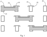
- Figs. 1 -3 relate to a new three-position disconnector switches in a number of different exemplar embodiments, where further specific exemplar embodiments are described below.
- the three-position disconnector switch comprises a power in contact 1, a piston 2, a power out contact 4, a plurality of flexible locking elements 5, an earthing contact 6, and a threaded rod 7.
- a length of the piston is such that in a first switch position an outer surface of a wall of the piston makes an electrical contact between the power in contact and the power out contact.
- the length of the piston is such that in a second switch position the outer surface of the wall of the piston does not make an electrical contact with either the earthing contact or the power in contact. In the second switch position the outer surface of the wall of the piston makes an electrical contact with the power out contact.
- the length of the piston is such that in a third switch position the outer surface of wall of the piston makes an electrical contact between the earthing contact and the power out contact.
- the piston comprises an inner threaded section configured to engage with the threaded rod. Rotation of the threaded rod is configured to engage with the inner threaded section to move the piston along an axis of the switch between the different switch positions.
- the piston comprises a groove extending in a direction parallel to the axis.
- Each of the flexible locking elements is configured such that a part of each of the flexible locking elements moves into and out of the groove as the piston is moved along the axis of the switch between the different switch positions as the piston is moved in both directions along the axis.
- the switch is configured such that there is always a part of at least one flexible locking element in the groove. When a part of at least one flexible locking element is in the groove the piston is constrained from rotating about the axis.
- each of the plurality of flexible locking elements is non-conducting.
- the power out contact comprises a first part and a second part.
- the first part is electrically connected to the second part.
- the outer surface of the wall of the piston makes a direct electrical contact with the first part of the power out contact and makes a direct electrical contact with the power in contact.
- the outer surface of the wall of the piston makes a direct electrical contact with the first part of the power out contact and makes a direct electrical contact with the second part of the power out contact.
- the outer surface of wall of the piston makes a direct electrical contact with the second part of the power out contact and makes a direct electrical contact with the earthing contact.
- a first flexible locking element (of the plurality of flexible locking elements) is connected to the power out contact and is on a side of the power out contact towards the power in contact and a second flexible locking element (of the plurality of flexible locking elements) is connected to the power out contact and is on a side of the power out contact towards the earthing contact.
- the part of the first flexible locking element in the first switch position the part of the first flexible locking element is in the groove.
- the part of the first flexible locking element is in the groove and the part of the second flexible locking element is in the groove.
- the part of the second flexible locking element in the third switch position the part of the second flexible locking element is in the groove.
- the part of the second flexible locking element in the first switch position the part of the second flexible locking element is not to be in the groove, and in the third switch position the part of the first flexible locking element is not in the groove.
- the first flexible locking element is connected to the first part of the power out contact and is on a side of the first part of the power out contact towards the power in contact and the second flexible locking element is connected to the second part of the power out contact and is on a side of the second part of the power out contact towards the earthing contact.
- the part of the first flexible locking element is in the groove.
- the part of the second flexible locking element is not in the groove.
- a third flexible locking element (of the plurality of locking elements) is connected to the first part of the power out contact and is on a side of the first part of the power out contact towards the earthing contact and a fourth flexible locking element (of the plurality of flexible locking elements) is connected to the second part of the power out contact and is on a side of the second part of the power out contact towards the power in contact.
- the part of the third flexible locking element In the second switch position the part of the third flexible locking element is in the groove and in the second switch position the part of the fourth flexible locking element is in the groove.
- the first flexible locking element is connected to the second part of the power out contact and is on a side of the second part of the power out contact towards the power in contact and the second flexible locking element is connected to the first part of the power out contact and is on a side of the first part of the power out contact towards the earthing contact.
- the part of the first flexible locking element is in the groove and the part of the second flexible locking element is in the groove.
- a third flexible locking element (of the plurality of flexible locking elements) is connected to the power in contact and is on a side of the power in contact towards the earthing contact and a fourth flexible locking element (of the plurality of flexible locking elements) is connected to the earthing contact and is on a side of the earthing contact towards the power in contact.
- the part of the third flexible locking element In the first switch position the part of the third flexible locking element is in the groove and in the third switch position the part of the fourth flexible locking element is in the groove.
- the part of the second flexible locking element in the first switch position the part of the second flexible locking element is not in the groove and in the third switch position the part of the first flexible locking element is not in the groove.
- the groove does not extend to a first distal end of the piston.
- the groove does not extend to a second distal end of the piston opposite to the first distal end.
- an end of the groove at the first distal end and an end of the groove at the second distal end are sloped.
- the plurality of flexible locking elements are configured to flex.
- the plurality of flexible locking elements are configured to flex such that the part of each flexible locking element moves substantially in a radial direction with respect to the axis of the switch.
- the flexible locking elements are configured to flex in an arcuate manner.
- one or more three-position disconnectors as described can be utilized in a low voltage, medium voltage of high voltage switchgear or control gear, where for example three such disconnectors can be utilized one for each phase of a three-phase system.
- Fig. 1 shows a specific detailed embodiment of a new three position disconnector switch. At the top of the figure is shown to disconnector switch in a first switch position.
- a piston 2 is at the left-hand position, and connects a busbar contact 1, also called a power in contact, to a left-hand part of middle contact 4, also referred to as a first part of a power out contact.
- the power out contact 4 actually has two parts, and flexible locking elements 5 extend either side of each part of the power out contact 4.
- the piston 2 has a groove 3 and one of the flexible locking elements 5 is located in the groove and stops the piston from rotating about an axis of the switch.
- the centre of the piston is threaded, and a screw thread 7 extends along the axis and rotation of the screw thread moves the piston along the axis, because it cannot rotate.
- the screw thread 7 is not shown in Fig. 1 , but is shown in Fig.2 .
- the centre picture shows the piston in a second switching position, where the piston is contacting both parts of the middle or power out contact 4.
- two flexible locking elements are located in the groove, stopping the piston from rotating axially.
- the bottom picture of Fig. 2 shows the piston in the third switch position, where it connects the right hand part or second part of the power out contact 4 with an earth or earthing contact 6, and here one flexible locking element is located in the groove stopping the piston from rotating axially.
- Fig. 2 shows a detailed view of the middle or power out contact, with the piston connecting both parts together, and where to flexible locking elements have parts located in the groove of the piston stopping the piston from rotating axially.
- the groove has sloping ends, and indeed the ends of the piston sloping.
- a third flexible locking element is encountered that extends from the left-hand side of the second part of the power out contact, and again is pushed outwards and then flexes downwards into the groove.
- the second and third flexible locking elements are located in the groove, as shown in the middle figure of Fig. 1 .
- the second flexible locking element exits the groove, and a fourth flexible locking element enters the groove, where at an intermediate stage there are two flexible locking elements in the groove, and finally when the piston is driven all the way to the third switching position only the fourth flexible locking element remains in the groove.
- the locking element flexible allows to the groove to be located on the piston partly somewhere in the middle section and the groove need not go all the way across the top of the piston and be open at the ends.
- Plastic covers/bearings can be utilized in which the flexible locking element is incorporated. It can be made in several pieces located on each part of the middle contact. This arrangement provides rotational locking along the whole way of the travel of the disconnector piston.
- Non-conductivity of the flexible locking elements means it doesn't shorten the air gap between middle contact and busbar or earth contact. Additional advantage of this setup is that the groove can be made outside of the contact area on the disconnector piston and thus it doesn't compromise contact performance.
Landscapes
- Gas-Insulated Switchgears (AREA)
- Contacts (AREA)
Claims (15)
- Trennschalter mit drei Stellungen, umfassend:- einen Leistungseingangskontakt (1);- einen Kolben (2);- einen Leistungsausgangskontakt (4);- eine Mehrzahl von flexiblen Verriegelungselementen (5) ;- einen Erdungskontakt (6); und- eine Gewindestange (7);wobei eine Länge des Kolbens derart ist, dass in einer ersten Schaltstellung eine Außenfläche einer Wand des Kolbens einen elektrischen Kontakt zwischen dem Leistungseingangskontakt und dem Leistungsausgangskontakt herstellt;wobei die Länge des Kolbens derart ist, dass in einer zweiten Schaltstellung die Außenfläche der Wand des Kolbens keinen elektrischen Kontakt mit dem Erdungskontakt oder dem Leistungseingangskontakt herstellt, und wobei in der zweiten Schaltstellung die Außenfläche der Wand des Kolbens einen elektrischen Kontakt mit dem Leistungsausgangskontakt herstellt;wobei die Länge des Kolbens derart ist, dass in einer dritten Schaltstellung die Außenfläche der Wand des Kolbens einen elektrischen Kontakt zwischen dem Erdungskontakt und dem Leistungsausgangskontakt herstellt;wobei der Kolben einen Innengewindeabschnitt umfasst, der zum Eingreifen mit der Gewindestange ausgelegt ist, und wobei eine Drehung der Gewindestange zum Eingreifen mit dem Innengewindeabschnitt ausgelegt ist, um den Kolben entlang einer Achse des Schalters zwischen den verschiedenen Schaltstellungen zu bewegen;wobei der Kolben eine Nut umfasst, die sich in einer Richtung parallel zu der Achse erstreckt;wobei jedes der flexiblen Verriegelungselemente derart ausgelegt ist, dass sich ein Teil jedes der flexiblen Verriegelungselemente in die und aus der Nut bewegt, während der Kolben entlang der Achse des Schalters zwischen den verschiedenen Schaltstellungen bewegt wird, während der Kolben in beide Richtungen entlang der Achse bewegt wird;wobei, während der Kolben entlang der Achse bewegt wird, der Schalter derart ausgelegt ist, dass sich stets ein Teil mindestens eines flexiblen Verriegelungselements in der Nut befindet; undwobei, wenn sich ein Teil mindestens eines flexiblen Verriegelungselements in der Nut befindet, der Kolben an einer Drehung um die Achse gehindert wird.
- Trennschalter mit drei Stellungen nach Anspruch 1, wobei jedes der Mehrzahl von flexiblen Verriegelungselementen nicht leitfähig ist.
- Trennschalter mit drei Stellungen nach einem der Ansprüche 1-2, wobei der Leistungsausgangskontakt einen ersten Teil und einen zweiten Teil umfasst, wobei der erste Teil mit dem zweiten Teil elektrisch verbunden ist, wobei in der ersten Schaltstellung die Außenfläche der Wand des Kolbens einen direkten elektrischen Kontakt mit dem ersten Teil des Leistungsausgangskontakts herstellt und einen direkten elektrischen Kontakt mit dem Leistungseingangskontakt herstellt, wobei in der zweiten Schaltstellung die Außenfläche der Wand des Kolbens einen direkten elektrischen Kontakt mit dem ersten Teil des Leistungsausgangskontakts herstellt und einen direkten elektrischen Kontakt mit dem zweiten Teil des Leistungsausgangskontakts herstellt, und wobei in der dritten Schaltstellung die Außenfläche der Wand des Kolbens einen direkten elektrischen Kontakt mit dem zweiten Teil des Leistungsausgangskontakts herstellt und einen direkten elektrischen Kontakt mit dem Erdungskontakt herstellt.
- Trennschalter mit drei Stellungen nach einem der Ansprüche 1-3, wobei ein erstes flexibles Verriegelungselement mit dem Leistungsausgangskontakt verbunden ist und sich auf einer Seite des Leistungsausgangskontakts hin zu dem Leistungseingangskontakt befindet und ein zweites flexibles Verriegelungselement mit dem Leistungsausgangskontakt verbunden ist und sich auf einer Seite des Leistungsausgangskontakts hin zu dem Erdungskontakt befindet.
- Trennschalter mit drei Stellungen nach Anspruch 4, wenn abhängig von einem der Ansprüche 1-2, wobei in der ersten Schaltstellung sich der Teil des ersten flexiblen Verriegelungselements in der Nut befindet, wobei in der zweiten Schaltstellung sich der Teil des ersten flexiblen Verriegelungselements in der Nut befindet und sich der Teil des zweiten flexiblen Verriegelungselements in der Nut befindet, und wobei in der dritten Schaltstellung sich der Teil des zweiten flexiblen Verriegelungselements in der Nut befindet.
- Trennschalter mit drei Stellungen nach Anspruch 5, wobei in der ersten Schaltstellung sich der Teil des zweiten flexiblen Verriegelungselements nicht in der Nut befinden soll, und wobei in der dritten Schaltstellung sich der Teil des ersten flexiblen Verriegelungselements nicht in der Nut befindet.
- Trennschalter mit drei Stellungen nach Anspruch 4, wenn abhängig von Anspruch 3, wobei das erste flexible Verriegelungselement mit dem ersten Teil des Leistungsausgangskontakts verbunden ist und sich auf einer Seite des ersten Teils des Leistungsausgangskontakts hin zu dem Leistungseingangskontakt befindet und das zweite flexible Verriegelungselement mit dem zweiten Teil des Leistungsausgangskontakts verbunden ist und sich auf einer Seite des zweiten Teils des Leistungsausgangskontakts hin zu dem Erdungskontakt befindet, und wobei in der ersten Schaltstellung sich der Teil des ersten flexiblen Verriegelungselements in der Nut befindet.
- Trennschalter mit drei Stellungen nach Anspruch 7, wobei in der ersten Schaltstellung sich der Teil des zweiten flexiblen Verriegelungselements nicht in der Nut befindet.
- Trennschalter mit drei Stellungen nach einem der Ansprüche 7-8, wobei ein drittes flexibles Verriegelungselement mit dem ersten Teil des Leistungsausgangskontakts verbunden ist und sich auf einer Seite des ersten Teils des Leistungsausgangskontakts hin zu dem Erdungskontakt befindet und ein viertes flexibles Verriegelungselement mit dem zweiten Teil des Leistungsausgangskontakts verbunden ist und sich auf einer Seite des zweiten Teils des Leistungsausgangskontakts hin zu dem Leistungseingangskontakt befindet, und wobei in der zweiten Schaltstellung sich der Teil des dritten flexiblen Verriegelungselements in der Nut befindet und in der zweiten Schaltstellung sich der Teil des vierten flexiblen Verriegelungselements in der Nut befindet.
- Trennschalter mit drei Stellungen nach Anspruch 4, wenn abhängig von Anspruch 3, wobei das erste flexible Verriegelungselement mit dem zweiten Teil des Leistungsausgangskontakts verbunden ist und sich auf einer Seite des zweiten Teils des Leistungsausgangskontakts hin zu dem Leistungseingangskontakt befindet und das zweite flexible Verriegelungselement mit dem ersten Teil des Leistungsausgangskontakts verbunden ist und sich auf einer Seite des ersten Teils des Leistungsausgangskontakts hin zu dem Erdungskontakt befindet, und wobei in der zweiten Schaltstellung sich der Teil des ersten flexiblen Verriegelungselements in der Nut befindet und sich der Teil des zweiten flexiblen Verriegelungselements in der Nut befindet.
- Trennschalter mit drei Stellungen nach Anspruch 10, wobei ein drittes flexibles Verriegelungselement mit dem Leistungseingangskontakt verbunden ist und sich auf einer Seite des Leistungseingangskontakts hin zu dem Erdungskontakt befindet und ein viertes flexibles Verriegelungselement mit dem Erdungskontakt verbunden ist und sich auf einer Seite des Erdungskontakts hin zu dem Leistungseingangskontakt befindet, und wobei in der ersten Schaltstellung sich der Teil des dritten flexiblen Verriegelungselements in der Nut befindet und wobei in der dritten Schaltstellung sich der Teil des vierten flexiblen Verriegelungselements in der Nut befindet.
- Trennschalter mit drei Stellungen nach Anspruch 11, wobei in der ersten Schaltstellung sich der Teil des zweiten flexiblen Verriegelungselements nicht in der Nut befindet und wobei in der dritten Schaltstellung sich der Teil des ersten flexiblen Verriegelungselements nicht in der Nut befindet.
- Trennschalter mit drei Stellungen nach einem der Ansprüche 1-12, wobei sich die Nut nicht zu einem ersten distalen Ende des Kolbens erstreckt, und optional wobei sich die Nut nicht zu einem zweiten distalen Ende des Kolbens gegenüber dem ersten distalen Ende erstreckt.
- Trennschalter mit drei Stellungen nach einem der Ansprüche 1-13, wobei die Mehrzahl von flexiblen Verriegelungselementen dazu ausgelegt sind, sich zu biegen.
- Niederspannungs-, Mittelspannungs- oder Hochspannungsschaltanlage oder -Steueranlage, umfassend einen oder mehrere Trennschalter mit drei Stellungen nach einem der Ansprüche 1-14.
Priority Applications (3)
| Application Number | Priority Date | Filing Date | Title |
|---|---|---|---|
| EP21173956.0A EP4089699B1 (de) | 2021-05-14 | 2021-05-14 | Trennschalter mit drei positionen |
| CN202210488989.XA CN115346824B (zh) | 2021-05-14 | 2022-05-06 | 三位置隔离开关 |
| US17/740,876 US11688569B2 (en) | 2021-05-14 | 2022-05-10 | Three-position disconnector switch |
Applications Claiming Priority (1)
| Application Number | Priority Date | Filing Date | Title |
|---|---|---|---|
| EP21173956.0A EP4089699B1 (de) | 2021-05-14 | 2021-05-14 | Trennschalter mit drei positionen |
Publications (2)
| Publication Number | Publication Date |
|---|---|
| EP4089699A1 EP4089699A1 (de) | 2022-11-16 |
| EP4089699B1 true EP4089699B1 (de) | 2023-11-29 |
Family
ID=75936796
Family Applications (1)
| Application Number | Title | Priority Date | Filing Date |
|---|---|---|---|
| EP21173956.0A Active EP4089699B1 (de) | 2021-05-14 | 2021-05-14 | Trennschalter mit drei positionen |
Country Status (3)
| Country | Link |
|---|---|
| US (1) | US11688569B2 (de) |
| EP (1) | EP4089699B1 (de) |
| CN (1) | CN115346824B (de) |
Family Cites Families (3)
| Publication number | Priority date | Publication date | Assignee | Title |
|---|---|---|---|---|
| EP1569254A1 (de) * | 2004-02-27 | 2005-08-31 | ABB Technology AG | Schaltgerät mit Trenn-und/oder Erdungsfunktion |
| EP3671789B1 (de) * | 2018-12-21 | 2021-06-23 | ABB Schweiz AG | Mittel- oder hochspannungsschaltgerät mit dreistellungsschalter |
| EP3754681B1 (de) * | 2019-06-21 | 2026-01-21 | ABB Schweiz AG | Trennschalter mit drei positionen |
-
2021
- 2021-05-14 EP EP21173956.0A patent/EP4089699B1/de active Active
-
2022
- 2022-05-06 CN CN202210488989.XA patent/CN115346824B/zh active Active
- 2022-05-10 US US17/740,876 patent/US11688569B2/en active Active
Also Published As
| Publication number | Publication date |
|---|---|
| CN115346824B (zh) | 2025-07-25 |
| US20220367132A1 (en) | 2022-11-17 |
| US11688569B2 (en) | 2023-06-27 |
| CN115346824A (zh) | 2022-11-15 |
| EP4089699A1 (de) | 2022-11-16 |
Similar Documents
| Publication | Publication Date | Title |
|---|---|---|
| CN1237679C (zh) | 一种气体绝缘开关装置 | |
| EP3671789B1 (de) | Mittel- oder hochspannungsschaltgerät mit dreistellungsschalter | |
| JP4388032B2 (ja) | 固体絶縁断路器 | |
| KR19980018452A (ko) | 금속 밀폐 가스 절연 고압 스위치 기어를 위한 분리/접지 스위치 | |
| CA1177866A (en) | Stiff flexible connector for a circuit breaker or other electrical apparatus | |
| KR101123915B1 (ko) | 차단 및/또는 접지 기능을 구비한 개폐 디바이스 | |
| WO2000024100A1 (en) | Gas-insulated switchgear device | |
| EP2728603B1 (de) | Dreiwegschalter für eine gasisolierte vorrichtung | |
| JP2007511887A (ja) | スイッチ断路器および/または接地用スイッチのためのスピンドル駆動機構 | |
| JP2002051416A (ja) | ガス絶縁開閉器 | |
| EP2645378B1 (de) | Elektrische Vorrichtung mit Isolatoren | |
| EP0147125B1 (de) | Last-Stufenwähler | |
| EP4089699A1 (de) | Trennschalter mit drei positionen | |
| EP3309808B1 (de) | Schaltvorrichtung für eine gasisolierte schaltanlage und gasisolierte schaltvorrichtung | |
| JP5298089B2 (ja) | 開閉器,開閉器ユニット,スイッチギヤ及びスイッチギヤを搭載した風車 | |
| EA030580B1 (ru) | Коммутационный аппарат для электроэнергетических систем | |
| EP4456106A1 (de) | Schalteinrichtung | |
| EP2461339B1 (de) | Schutzschalterpol | |
| US11651917B2 (en) | Electrode driving device for gas insulated switchgear | |
| EP3696836B1 (de) | Schalter für eine mittel- oder hochspannungsschaltanlage | |
| CN113035627B (zh) | 一种单体分箱式线性三位置开关结构及其使用方法 | |
| JP4764287B2 (ja) | ガス絶縁開閉器 | |
| EP3754685B1 (de) | Schaltpol eines mittelspannungsschutzschalters | |
| EP4432324B1 (de) | Schaltanlagenarchitektur | |
| EP4089698B1 (de) | Trennschalter mit drei positionen |
Legal Events
| Date | Code | Title | Description |
|---|---|---|---|
| PUAI | Public reference made under article 153(3) epc to a published international application that has entered the european phase |
Free format text: ORIGINAL CODE: 0009012 |
|
| STAA | Information on the status of an ep patent application or granted ep patent |
Free format text: STATUS: THE APPLICATION HAS BEEN PUBLISHED |
|
| AK | Designated contracting states |
Kind code of ref document: A1 Designated state(s): AL AT BE BG CH CY CZ DE DK EE ES FI FR GB GR HR HU IE IS IT LI LT LU LV MC MK MT NL NO PL PT RO RS SE SI SK SM TR |
|
| STAA | Information on the status of an ep patent application or granted ep patent |
Free format text: STATUS: REQUEST FOR EXAMINATION WAS MADE |
|
| 17P | Request for examination filed |
Effective date: 20230427 |
|
| RBV | Designated contracting states (corrected) |
Designated state(s): AL AT BE BG CH CY CZ DE DK EE ES FI FR GB GR HR HU IE IS IT LI LT LU LV MC MK MT NL NO PL PT RO RS SE SI SK SM TR |
|
| GRAP | Despatch of communication of intention to grant a patent |
Free format text: ORIGINAL CODE: EPIDOSNIGR1 |
|
| STAA | Information on the status of an ep patent application or granted ep patent |
Free format text: STATUS: GRANT OF PATENT IS INTENDED |
|
| INTG | Intention to grant announced |
Effective date: 20230719 |
|
| GRAS | Grant fee paid |
Free format text: ORIGINAL CODE: EPIDOSNIGR3 |
|
| GRAA | (expected) grant |
Free format text: ORIGINAL CODE: 0009210 |
|
| STAA | Information on the status of an ep patent application or granted ep patent |
Free format text: STATUS: THE PATENT HAS BEEN GRANTED |
|
| AK | Designated contracting states |
Kind code of ref document: B1 Designated state(s): AL AT BE BG CH CY CZ DE DK EE ES FI FR GB GR HR HU IE IS IT LI LT LU LV MC MK MT NL NO PL PT RO RS SE SI SK SM TR |
|
| REG | Reference to a national code |
Ref country code: GB Ref legal event code: FG4D |
|
| REG | Reference to a national code |
Ref country code: CH Ref legal event code: EP |
|
| REG | Reference to a national code |
Ref country code: DE Ref legal event code: R096 Ref document number: 602021007192 Country of ref document: DE |
|
| REG | Reference to a national code |
Ref country code: IE Ref legal event code: FG4D |
|
| REG | Reference to a national code |
Ref country code: LT Ref legal event code: MG9D |
|
| REG | Reference to a national code |
Ref country code: NL Ref legal event code: MP Effective date: 20231129 |
|
| PG25 | Lapsed in a contracting state [announced via postgrant information from national office to epo] |
Ref country code: GR Free format text: LAPSE BECAUSE OF FAILURE TO SUBMIT A TRANSLATION OF THE DESCRIPTION OR TO PAY THE FEE WITHIN THE PRESCRIBED TIME-LIMIT Effective date: 20240301 |
|
| PG25 | Lapsed in a contracting state [announced via postgrant information from national office to epo] |
Ref country code: IS Free format text: LAPSE BECAUSE OF FAILURE TO SUBMIT A TRANSLATION OF THE DESCRIPTION OR TO PAY THE FEE WITHIN THE PRESCRIBED TIME-LIMIT Effective date: 20240329 |
|
| PG25 | Lapsed in a contracting state [announced via postgrant information from national office to epo] |
Ref country code: LT Free format text: LAPSE BECAUSE OF FAILURE TO SUBMIT A TRANSLATION OF THE DESCRIPTION OR TO PAY THE FEE WITHIN THE PRESCRIBED TIME-LIMIT Effective date: 20231129 |
|
| PG25 | Lapsed in a contracting state [announced via postgrant information from national office to epo] |
Ref country code: ES Free format text: LAPSE BECAUSE OF FAILURE TO SUBMIT A TRANSLATION OF THE DESCRIPTION OR TO PAY THE FEE WITHIN THE PRESCRIBED TIME-LIMIT Effective date: 20231129 |
|
| PG25 | Lapsed in a contracting state [announced via postgrant information from national office to epo] |
Ref country code: LT Free format text: LAPSE BECAUSE OF FAILURE TO SUBMIT A TRANSLATION OF THE DESCRIPTION OR TO PAY THE FEE WITHIN THE PRESCRIBED TIME-LIMIT Effective date: 20231129 Ref country code: IS Free format text: LAPSE BECAUSE OF FAILURE TO SUBMIT A TRANSLATION OF THE DESCRIPTION OR TO PAY THE FEE WITHIN THE PRESCRIBED TIME-LIMIT Effective date: 20240329 Ref country code: GR Free format text: LAPSE BECAUSE OF FAILURE TO SUBMIT A TRANSLATION OF THE DESCRIPTION OR TO PAY THE FEE WITHIN THE PRESCRIBED TIME-LIMIT Effective date: 20240301 Ref country code: ES Free format text: LAPSE BECAUSE OF FAILURE TO SUBMIT A TRANSLATION OF THE DESCRIPTION OR TO PAY THE FEE WITHIN THE PRESCRIBED TIME-LIMIT Effective date: 20231129 Ref country code: BG Free format text: LAPSE BECAUSE OF FAILURE TO SUBMIT A TRANSLATION OF THE DESCRIPTION OR TO PAY THE FEE WITHIN THE PRESCRIBED TIME-LIMIT Effective date: 20240229 |
|
| REG | Reference to a national code |
Ref country code: AT Ref legal event code: MK05 Ref document number: 1637007 Country of ref document: AT Kind code of ref document: T Effective date: 20231129 |
|
| PG25 | Lapsed in a contracting state [announced via postgrant information from national office to epo] |
Ref country code: NL Free format text: LAPSE BECAUSE OF FAILURE TO SUBMIT A TRANSLATION OF THE DESCRIPTION OR TO PAY THE FEE WITHIN THE PRESCRIBED TIME-LIMIT Effective date: 20231129 |
|
| PG25 | Lapsed in a contracting state [announced via postgrant information from national office to epo] |
Ref country code: SE Free format text: LAPSE BECAUSE OF FAILURE TO SUBMIT A TRANSLATION OF THE DESCRIPTION OR TO PAY THE FEE WITHIN THE PRESCRIBED TIME-LIMIT Effective date: 20231129 Ref country code: RS Free format text: LAPSE BECAUSE OF FAILURE TO SUBMIT A TRANSLATION OF THE DESCRIPTION OR TO PAY THE FEE WITHIN THE PRESCRIBED TIME-LIMIT Effective date: 20231129 Ref country code: PL Free format text: LAPSE BECAUSE OF FAILURE TO SUBMIT A TRANSLATION OF THE DESCRIPTION OR TO PAY THE FEE WITHIN THE PRESCRIBED TIME-LIMIT Effective date: 20231129 Ref country code: NO Free format text: LAPSE BECAUSE OF FAILURE TO SUBMIT A TRANSLATION OF THE DESCRIPTION OR TO PAY THE FEE WITHIN THE PRESCRIBED TIME-LIMIT Effective date: 20240229 Ref country code: NL Free format text: LAPSE BECAUSE OF FAILURE TO SUBMIT A TRANSLATION OF THE DESCRIPTION OR TO PAY THE FEE WITHIN THE PRESCRIBED TIME-LIMIT Effective date: 20231129 Ref country code: LV Free format text: LAPSE BECAUSE OF FAILURE TO SUBMIT A TRANSLATION OF THE DESCRIPTION OR TO PAY THE FEE WITHIN THE PRESCRIBED TIME-LIMIT Effective date: 20231129 Ref country code: HR Free format text: LAPSE BECAUSE OF FAILURE TO SUBMIT A TRANSLATION OF THE DESCRIPTION OR TO PAY THE FEE WITHIN THE PRESCRIBED TIME-LIMIT Effective date: 20231129 |
|
| PG25 | Lapsed in a contracting state [announced via postgrant information from national office to epo] |
Ref country code: DK Free format text: LAPSE BECAUSE OF FAILURE TO SUBMIT A TRANSLATION OF THE DESCRIPTION OR TO PAY THE FEE WITHIN THE PRESCRIBED TIME-LIMIT Effective date: 20231129 |
|
| PG25 | Lapsed in a contracting state [announced via postgrant information from national office to epo] |
Ref country code: CZ Free format text: LAPSE BECAUSE OF FAILURE TO SUBMIT A TRANSLATION OF THE DESCRIPTION OR TO PAY THE FEE WITHIN THE PRESCRIBED TIME-LIMIT Effective date: 20231129 Ref country code: AT Free format text: LAPSE BECAUSE OF FAILURE TO SUBMIT A TRANSLATION OF THE DESCRIPTION OR TO PAY THE FEE WITHIN THE PRESCRIBED TIME-LIMIT Effective date: 20231129 |
|
| PG25 | Lapsed in a contracting state [announced via postgrant information from national office to epo] |
Ref country code: SK Free format text: LAPSE BECAUSE OF FAILURE TO SUBMIT A TRANSLATION OF THE DESCRIPTION OR TO PAY THE FEE WITHIN THE PRESCRIBED TIME-LIMIT Effective date: 20231129 |
|
| PG25 | Lapsed in a contracting state [announced via postgrant information from national office to epo] |
Ref country code: SM Free format text: LAPSE BECAUSE OF FAILURE TO SUBMIT A TRANSLATION OF THE DESCRIPTION OR TO PAY THE FEE WITHIN THE PRESCRIBED TIME-LIMIT Effective date: 20231129 Ref country code: SK Free format text: LAPSE BECAUSE OF FAILURE TO SUBMIT A TRANSLATION OF THE DESCRIPTION OR TO PAY THE FEE WITHIN THE PRESCRIBED TIME-LIMIT Effective date: 20231129 Ref country code: RO Free format text: LAPSE BECAUSE OF FAILURE TO SUBMIT A TRANSLATION OF THE DESCRIPTION OR TO PAY THE FEE WITHIN THE PRESCRIBED TIME-LIMIT Effective date: 20231129 Ref country code: EE Free format text: LAPSE BECAUSE OF FAILURE TO SUBMIT A TRANSLATION OF THE DESCRIPTION OR TO PAY THE FEE WITHIN THE PRESCRIBED TIME-LIMIT Effective date: 20231129 Ref country code: DK Free format text: LAPSE BECAUSE OF FAILURE TO SUBMIT A TRANSLATION OF THE DESCRIPTION OR TO PAY THE FEE WITHIN THE PRESCRIBED TIME-LIMIT Effective date: 20231129 Ref country code: CZ Free format text: LAPSE BECAUSE OF FAILURE TO SUBMIT A TRANSLATION OF THE DESCRIPTION OR TO PAY THE FEE WITHIN THE PRESCRIBED TIME-LIMIT Effective date: 20231129 Ref country code: AT Free format text: LAPSE BECAUSE OF FAILURE TO SUBMIT A TRANSLATION OF THE DESCRIPTION OR TO PAY THE FEE WITHIN THE PRESCRIBED TIME-LIMIT Effective date: 20231129 |
|
| PG25 | Lapsed in a contracting state [announced via postgrant information from national office to epo] |
Ref country code: PT Free format text: LAPSE BECAUSE OF FAILURE TO SUBMIT A TRANSLATION OF THE DESCRIPTION OR TO PAY THE FEE WITHIN THE PRESCRIBED TIME-LIMIT Effective date: 20240401 |
|
| PG25 | Lapsed in a contracting state [announced via postgrant information from national office to epo] |
Ref country code: PT Free format text: LAPSE BECAUSE OF FAILURE TO SUBMIT A TRANSLATION OF THE DESCRIPTION OR TO PAY THE FEE WITHIN THE PRESCRIBED TIME-LIMIT Effective date: 20240401 |
|
| REG | Reference to a national code |
Ref country code: DE Ref legal event code: R097 Ref document number: 602021007192 Country of ref document: DE |
|
| PLBE | No opposition filed within time limit |
Free format text: ORIGINAL CODE: 0009261 |
|
| STAA | Information on the status of an ep patent application or granted ep patent |
Free format text: STATUS: NO OPPOSITION FILED WITHIN TIME LIMIT |
|
| PG25 | Lapsed in a contracting state [announced via postgrant information from national office to epo] |
Ref country code: SI Free format text: LAPSE BECAUSE OF FAILURE TO SUBMIT A TRANSLATION OF THE DESCRIPTION OR TO PAY THE FEE WITHIN THE PRESCRIBED TIME-LIMIT Effective date: 20231129 |
|
| PG25 | Lapsed in a contracting state [announced via postgrant information from national office to epo] |
Ref country code: SI Free format text: LAPSE BECAUSE OF FAILURE TO SUBMIT A TRANSLATION OF THE DESCRIPTION OR TO PAY THE FEE WITHIN THE PRESCRIBED TIME-LIMIT Effective date: 20231129 |
|
| 26N | No opposition filed |
Effective date: 20240830 |
|
| REG | Reference to a national code |
Ref country code: CH Ref legal event code: PL |
|
| PG25 | Lapsed in a contracting state [announced via postgrant information from national office to epo] |
Ref country code: MC Free format text: LAPSE BECAUSE OF FAILURE TO SUBMIT A TRANSLATION OF THE DESCRIPTION OR TO PAY THE FEE WITHIN THE PRESCRIBED TIME-LIMIT Effective date: 20231129 |
|
| PG25 | Lapsed in a contracting state [announced via postgrant information from national office to epo] |
Ref country code: LU Free format text: LAPSE BECAUSE OF NON-PAYMENT OF DUE FEES Effective date: 20240514 |
|
| PG25 | Lapsed in a contracting state [announced via postgrant information from national office to epo] |
Ref country code: MC Free format text: LAPSE BECAUSE OF FAILURE TO SUBMIT A TRANSLATION OF THE DESCRIPTION OR TO PAY THE FEE WITHIN THE PRESCRIBED TIME-LIMIT Effective date: 20231129 Ref country code: LU Free format text: LAPSE BECAUSE OF NON-PAYMENT OF DUE FEES Effective date: 20240514 Ref country code: CH Free format text: LAPSE BECAUSE OF NON-PAYMENT OF DUE FEES Effective date: 20240531 |
|
| REG | Reference to a national code |
Ref country code: BE Ref legal event code: MM Effective date: 20240531 |
|
| PG25 | Lapsed in a contracting state [announced via postgrant information from national office to epo] |
Ref country code: IE Free format text: LAPSE BECAUSE OF NON-PAYMENT OF DUE FEES Effective date: 20240514 |
|
| PG25 | Lapsed in a contracting state [announced via postgrant information from national office to epo] |
Ref country code: BE Free format text: LAPSE BECAUSE OF NON-PAYMENT OF DUE FEES Effective date: 20240531 |
|
| PGFP | Annual fee paid to national office [announced via postgrant information from national office to epo] |
Ref country code: DE Payment date: 20250521 Year of fee payment: 5 |
|
| PGFP | Annual fee paid to national office [announced via postgrant information from national office to epo] |
Ref country code: IT Payment date: 20250527 Year of fee payment: 5 |
|
| PGFP | Annual fee paid to national office [announced via postgrant information from national office to epo] |
Ref country code: FR Payment date: 20250528 Year of fee payment: 5 |
|
| PG25 | Lapsed in a contracting state [announced via postgrant information from national office to epo] |
Ref country code: CY Free format text: LAPSE BECAUSE OF FAILURE TO SUBMIT A TRANSLATION OF THE DESCRIPTION OR TO PAY THE FEE WITHIN THE PRESCRIBED TIME-LIMIT; INVALID AB INITIO Effective date: 20210514 |
|
| PG25 | Lapsed in a contracting state [announced via postgrant information from national office to epo] |
Ref country code: HU Free format text: LAPSE BECAUSE OF FAILURE TO SUBMIT A TRANSLATION OF THE DESCRIPTION OR TO PAY THE FEE WITHIN THE PRESCRIBED TIME-LIMIT; INVALID AB INITIO Effective date: 20210514 |
|
| PG25 | Lapsed in a contracting state [announced via postgrant information from national office to epo] |
Ref country code: FI Free format text: LAPSE BECAUSE OF FAILURE TO SUBMIT A TRANSLATION OF THE DESCRIPTION OR TO PAY THE FEE WITHIN THE PRESCRIBED TIME-LIMIT Effective date: 20231129 |
|
| GBPC | Gb: european patent ceased through non-payment of renewal fee |
Effective date: 20250514 |
|
| PG25 | Lapsed in a contracting state [announced via postgrant information from national office to epo] |
Ref country code: GB Free format text: LAPSE BECAUSE OF NON-PAYMENT OF DUE FEES Effective date: 20250514 |