EP3696836B1 - Schalter für eine mittel- oder hochspannungsschaltanlage - Google Patents
Schalter für eine mittel- oder hochspannungsschaltanlage Download PDFInfo
- Publication number
- EP3696836B1 EP3696836B1 EP19157848.3A EP19157848A EP3696836B1 EP 3696836 B1 EP3696836 B1 EP 3696836B1 EP 19157848 A EP19157848 A EP 19157848A EP 3696836 B1 EP3696836 B1 EP 3696836B1
- Authority
- EP
- European Patent Office
- Prior art keywords
- contact
- switch
- mode
- flexible link
- flexible
- Prior art date
- Legal status (The legal status is an assumption and is not a legal conclusion. Google has not performed a legal analysis and makes no representation as to the accuracy of the status listed.)
- Active
Links
Images


Classifications
-
- H—ELECTRICITY
- H01—ELECTRIC ELEMENTS
- H01H—ELECTRIC SWITCHES; RELAYS; SELECTORS; EMERGENCY PROTECTIVE DEVICES
- H01H31/00—Air-break switches for high tension without arc-extinguishing or arc-preventing means
- H01H31/02—Details
- H01H31/026—Movable parts and contacts mounted thereon
-
- H—ELECTRICITY
- H01—ELECTRIC ELEMENTS
- H01H—ELECTRIC SWITCHES; RELAYS; SELECTORS; EMERGENCY PROTECTIVE DEVICES
- H01H3/00—Mechanisms for operating contacts
- H01H3/32—Driving mechanisms, i.e. for transmitting driving force to the contacts
- H01H3/36—Driving mechanisms, i.e. for transmitting driving force to the contacts using belt, chain, or cord
-
- H—ELECTRICITY
- H01—ELECTRIC ELEMENTS
- H01H—ELECTRIC SWITCHES; RELAYS; SELECTORS; EMERGENCY PROTECTIVE DEVICES
- H01H31/00—Air-break switches for high tension without arc-extinguishing or arc-preventing means
- H01H31/003—Earthing switches
-
- H—ELECTRICITY
- H01—ELECTRIC ELEMENTS
- H01H—ELECTRIC SWITCHES; RELAYS; SELECTORS; EMERGENCY PROTECTIVE DEVICES
- H01H31/00—Air-break switches for high tension without arc-extinguishing or arc-preventing means
- H01H31/02—Details
- H01H31/023—Base and stationary contacts mounted thereon
-
- H—ELECTRICITY
- H01—ELECTRIC ELEMENTS
- H01H—ELECTRIC SWITCHES; RELAYS; SELECTORS; EMERGENCY PROTECTIVE DEVICES
- H01H31/00—Air-break switches for high tension without arc-extinguishing or arc-preventing means
- H01H31/26—Air-break switches for high tension without arc-extinguishing or arc-preventing means with movable contact that remains electrically connected to one line in open position of switch
- H01H31/32—Air-break switches for high tension without arc-extinguishing or arc-preventing means with movable contact that remains electrically connected to one line in open position of switch with rectilinearly-movable contact
-
- H—ELECTRICITY
- H02—GENERATION; CONVERSION OR DISTRIBUTION OF ELECTRIC POWER
- H02B—BOARDS, SUBSTATIONS OR SWITCHING ARRANGEMENTS FOR THE SUPPLY OR DISTRIBUTION OF ELECTRIC POWER
- H02B13/00—Arrangement of switchgear in which switches are enclosed in, or structurally associated with, a casing, e.g. cubicle
- H02B13/02—Arrangement of switchgear in which switches are enclosed in, or structurally associated with, a casing, e.g. cubicle with metal casing
- H02B13/035—Gas-insulated switchgear
- H02B13/075—Earthing arrangements
Definitions
- the present invention relates to a switch that has utility as a two position or three position switch in an air-insulated or gas-insulated switchgear for medium voltage or high voltage applications.
- Contact systems for two or three position disconnectors for switchgear are actuated by different techniques, comprising for example levers, spindles, push rods, in order to move the switch into each of its end positions.
- the task is to move the switch to a particular position and keep it in its position, whilst under load by nominal current and also during a situation when short circuit current flows.
- lever based actuation usual creates discontinuous transmission, whilst spindle based activation does not exhibit discontinuities to the same extent, but is valid for only several rotations, and the thread required to be produced on the bolt and nut needs a high accuracy and is therefore costly.
- push rod based actuation requires significant space for the actuation movement.
- EP1361633A2 describes a A gas insulated switchgear capable of reducing the size and quantity of the component pans thereof and also reducing the size of the entire body thereof by effectively utilizing a space inside a container, comprising a bus conductor stored in a container earthed and sealed with insulating gas, two fixed collectors installed in the same direction as the bus conductor, a contact member disposed so as to be opposed to the collectors, and a movable contact conductor slidably inserted into the contact member and switching on and off the fixed collectors and the contact member, characterized in that a three-way disconnect and connect switch can be formed by forming one fixed collector in a disconnect part and the other fixed collector in an earthed stale so as to form an earthed switch.
- US2002/104827A1 describes a gas insulated switchgear capable of performing maintenance and inspection of a breaker without shutting down a bus line, which comprises a first metallic case containing a breaker and having a bushing for leading a load; and a second metallic case containing a plurality of disconnectors and having a plurality of bushings for leading a bus line to be connected to the disconnectors, wherein the first metallic case and the second metallic case are connected to each other through a gas partition spacer.
- a rigid power transmission device comprises a chain holding rack, a chain wheel, chains, a three-position switch movable contact and a housing.
- the chain holding rack is U-shaped.
- the chains are arranged on the chain holding rack.
- the chain wheel and the chains are arranged in a matched manner. When the chain wheel rotates, the chains move along the chain holding rack.
- the three-position switch movable contact is arranged in the housing through conductive springs.
- the lower end of the three-position switch movable contact is connected with one end of the chain wheel.
- the upper end of the three-position switch movable contact is connected with an isolating switch movable contact.
- the isolating switch movable contact, the three-position switch movable contact, and the chains connected with the lower end of the three-position switch movable contact are arranged on the same vertical line.
- the rigid power transmission device drives the chain to perform vertical linear motion through rotation of the chain wheel to control the isolation switch movable contact to move vertically so as to control the switching-on and switching-off of a vacuum breaker, enables the vacuum breaker to be compact in structure, small in parts, low in cost, simple in structure and practical.
- Appended claim 1 defines a switch for a medium voltage or high voltage switchgear.
- Appended claim 16 defines a medium voltage or high voltage switchgear.
- a switch for a medium voltage or high voltage switchgear comprising:
- the moveable contact In an on state of the switch the moveable contact is configured to be in a position that connects the first fixed contact to the second fixed contact. In an off state of the switch the moveable contact is configured to be in a position where the first fixed contact is not connected to the second fixed contact.
- the at least one flexible link is connected to the moveable contact.
- the at least one flexible link engages with the contact drive.
- the contact drive is configured to pull the moveable contact via the at least one flexible link and the contact drive is configured to push the moveable contact via the at least one flexible link.
- Activation of the contact drive in a first mode is configured to move the moveable contact to the position such that the switch is in the on state.
- Activation of the contact drive in a second mode is drive is configured to move the moveable contact to the position such that the switch is in the off state.
- an actuation element that utilizes a flexible link to enable continuous transmission for the switching from one state to another state (on-off and vice versa is provided), and where less space is required because the flexible link can be coiled or collapsed as it is pulled.
- the switch comprises a fixed earth contact.
- the moveable contact In an earthing state of the switch the moveable contact is configured to be in a position that connects the second fixed contact to the earthing fixed contact.
- Activation of the contact drive in a third mode is configured to move the moveable contact to the position such that the switch is in the earthing state.
- the switch comprises a link guide. At least part of the at least one flexible link is configured to run within or adjacent to the link guide in a longitudinal direction.
- the link guide is configured to inhibit the at least one flexible link from flexing in a direction perpendicular to the longitudinal direction.
- the link guide in stopping the flexible link from deforming it at least one direction, enables high axial forces to be applied during pushing actuation as well as pulling actuation.
- the contact drive comprises at least one cog wheel configured to engage with the at least one flexible link.
- a simple mechanism if provided for pulling and pushing the flexible link through rotation of a cog wheel, that for example has teeth to engage with a flexible link in the form of a chain or notches or ridges to engage with a flexible link in the form of a toothed belt.
- rotation of a cog wheel of the at least one cog wheel in a first direction is configured to pull a flexible link
- rotation of the cog wheel in a direction counter to the first direction is configured to push the flexible link
- the at least one flexible link is two flexible links.
- a flexible link guide may not be required, because the flexible links can be configured to resist bending when being pushed as well as when being pulled.
- the at least one cog wheel is two cog wheels.
- Rotation of a first cog wheel of the two cog wheels in a first direction is configured to pull a first flexible link of the two flexible links and rotation of a second cog wheel of the two cog wheels in a second direction counter to the first direction is configured to pull a second flexible link of the two flexible links.
- rotation of the first cog wheel of the two cog wheels in the second direction is configured to push the first flexible link of the two flexible links and rotation of the second cog wheel of the two cog wheels in the first direction is configured to push the second flexible link of the two flexible links.
- the two flexible links are provided back to back.
- flexible links in the form of push chains that resist bending in one direction but can be bent in the other direction can be placed back to back such that they resist bending outwards away from each other. Then, during pushing they form a single flexible link that resists bending and that can apply high axial forces, and similarly can apply high axial forces when pulled and that can still be collapsed or coiled into two sets of collapsed or coiled flexible links.
- the at least one flexible link comprises at least one chain.
- the at least one chain comprises a push chain.
- the push chain when extended in a longitudinal axis, is configured to enable the chain to bend out of the axis in a first direction perpendicular to the axis and configured to resist the chain being bent out of the axis in a second direction opposite to the first direction.
- the at least one flexible link comprises at least one toothed belt.
- the switch is configured to transition between the second mode and the third mode without entering the first mode.
- the switch can move from an off state to an earthing state, and vice versa, without entering the on state.
- the at least one cog wheel is configured to rotate through less that one revolution when the switch transitions between the second mode and the third mode. In this manner, a two or three position switch is provided where actuation is facilitated by less than one rotation of a cog wheel.
- the contact drive is configured to pull the at least one flexible link to transition from the second mode to the third mode.
- the contact drive is configured to push the at least one flexible link to transition from the third mode to the second mode.
- the switch is configured to transition between the second mode and the first mode without entering the third mode.
- the switch can move from an off state to an on state, and vice versa, without entering the earthing state.
- the at least one cog wheel is configured to rotate through less that one revolution when the switch transitions between the second mode and the first mode.
- a two or three position switch is provided where actuation is facilitated by less than one rotation of a cog wheel.
- the contact drive is configured to push the at least one flexible link to transition from the second mode to the first mode.
- the contact drive is configured to pull the at least one flexible link to transition from the first mode to the second mode.
- the switch comprises a compartment configured to accommodate a length of the at least one flexible link when the contact drive pulls the at least one flexible link.
- a maximum internal dimension of the compartment is less than the length of the at least one flexible link.
- a medium voltage or high voltage switchgear comprising at least one switch according to the first aspect.
- Figs. 1-6 relate to a switch for a medium voltage or high voltage switchgear.
- the switch comprises a first fixed contact, a second fixed contact, a moveable contact, at least one flexible link, and a contact drive.
- the moveable contact In an on state of the switch the moveable contact is configured to be in a position that connects the first fixed contact to the second fixed contact.
- the moveable contact In an off state of the switch the moveable contact is configured to be in a position where the first fixed contact is not connected to the second fixed contact.
- the at least one flexible link is connected to the moveable contact.
- the at least one flexible link engages with the contact drive.
- the contact drive is configured to pull the moveable contact via the at least one flexible link.
- the contact drive is configured also to push the moveable contact via the at least one flexible link.
- Activation of the contact drive in a first mode is configured to move the moveable contact to the position such that the switch is in the on state.
- Activation of the contact drive in a second mode is drive is configured to move the moveable contact to the position such that the switch is in the off state.
- the on state relates to current being able to flow from the first fixed contact to the second fixed contact via the moveable contact.
- the moveable contact in the off state is configured to be located substantially within the second fixed contact.
- the first fixed contact is a disconnector contact.
- the second fixed contact is a middle contact.
- switch comprises a fixed earth contact.
- the moveable contact In an earthing state of the switch the moveable contact is configured to be in a position that connects the second fixed contact to the earthing fixed contact.
- Activation of the contact drive in a third mode is configured to move the moveable contact to the position such that the switch is in the earthing state.
- the switch comprises a link guide. At least part of the at least one flexible link is configured to run within or adjacent to the link guide in a longitudinal direction.
- the link guide is configured to inhibit or resist the at least one flexible link from flexing in a direction perpendicular to the longitudinal direction.
- the link guide is located on only one side of the flexible link.
- the link guide is located on at least opposing sides of the flexible link.
- the contact drive comprises at least one cog wheel configured to engage with the at least one flexible link.
- the at least one flexible link is two flexible links.
- the at least one cog wheel is two cog wheels.
- Rotation of a first cog wheel of the two cog wheels in a first direction is configured to pull a first flexible link of the two flexible links and rotation of a second cog wheel of the two cog wheels in a second direction counter to the first direction is configured to pull a second flexible link of the two flexible links. Then rotation of the first cog wheel of the two cog wheels in the second direction is configured to push the first flexible link of the two flexible links and rotation of the second cog wheel of the two cog wheels in the first direction is configured to push the second flexible link of the two flexible links.
- the at least one flexible link comprises at least one chain.
- the at least one chain comprises a push chain.
- the push chain when extended in a longitudinal axis is configured to enable the chain to bend out of the axis in a first direction perpendicular to the axis and configured to resist the chain being bent out of the axis in a second direction opposite to the first direction.
- the at least one flexible link comprises at least one toothed belt.
- the switch is configured to transition between the second mode and the third mode without entering the first mode.
- the at least one cog wheel is configured to rotate through less that one revolution when the switch transitions between the second mode and the third mode.
- the contact drive is configured to pull the at least one flexible link to transition from the second mode to the third mode.
- the contact drive is configured to push the at least one flexible link to transition from the third mode to the second mode.
- the switch is configured to transition between the second mode and the first mode without entering the third mode.
- the at least one cog wheel is configured to rotate through less that one revolution when the switch transitions between the second mode and the first mode.
- the at least one cog wheel is configured to rotate through less that one revolution when the switch transitions between the first mode and the third mode.
- the switch can move from an on state through an off state to an earthing state via less than one rotation of an actuating cog wheel.
- the contact drive is configured to push the at least one flexible link to transition from the second mode to the first mode.
- the contact drive is configured to pull the at least one flexible link to transition from the first mode to the second mode.
- the switch comprises a compartment configured to accommodate a length of the at least one flexible link when the contact drive pulls the at least one flexible link.
- a maximum internal dimension of the compartment is less than the length of the at least one flexible link that resides in the compartment.
- the switch as described in any example above finds utility in a medium voltage or high voltage switchgear.
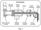
- a push chain of the switch is attached or connected to a moving or movable contact.
- the push chain engages with a cog wheel, and is partially wrapped around the cog wheel, where teeth of the cog wheel protrude into and through the chain.
- rotation of the cog wheel pulls or pushes the push chain is required.
- a push chain is a chain that is bending resistant at one side and limp at the opposite side.
- the switch also has a disconnector contact at one end, a middle contact in the centre, and an earthing contact at the end closest to the cog wheel.
- the cog wheel forms part of a contact drive, having a motor and control electronics that are not shown.
- a chain guide is provided, shown in more detail in Fig. 4 .
- push chain can flex in one direction but resists flexing in the other direction, and the chain guide is provided on the side that the push chain can flex.
- the push chain cannot then flex.
- the push chain can transfer high forces in an longitudinal direction, via a push and pull system that is actuated by a chain wheel or cog wheel.
- the cog wheel has rotated in an anticlockwise direction and the push chain has pushed the movable contact to the left until it connects the disconnector contact with the middle contact, and the disconnector is then in an on position. Then, as shown in Fig.
- the chain can collapse in a provided room and does not need more space.
- An advantage is to have an actuation element which can actuate a contact system by less than one rotation together, with the advantage that a continuous transmission is provided with less demand for space.
- a further advantage is that the drive is independent of the position of the contact system in relation to the orientation (horizontal, vertical, diagonal). Also, the connection of the push chain to the movable contact is relatively simple. Also, by using a push chain activation can be facilitated through only one mechanic bush, lead to less parts and to less risk of leakage during actuation.
- two chains or two toothed belts are used. This is shown in Fig. 5 , where to push chains are used back-to-back, where they can only flex towards each other and therefore as a pair cannot then flex when located back-to-back, but can still flex behind the cog wheel and be stored in space-saving manner.
- the two chains acting in this manner can still pull the movable contact and pushed the movable contact with high force, and in this case a chain guide is not required, although clearly could still be utilised.
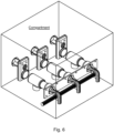
- Fig. 6 shows an example of three switches in a compartment of a medium voltage or high voltage switchgear, with the three switches shown in the earthing on state.
Landscapes
- Engineering & Computer Science (AREA)
- Power Engineering (AREA)
- Mechanisms For Operating Contacts (AREA)
- Driving Mechanisms And Operating Circuits Of Arc-Extinguishing High-Tension Switches (AREA)
Claims (16)
- Schalter für eine Mittelspannungs- oder Hochspannungsschaltanlage, wobei der Schalter Folgendes umfasst:- einen ersten festen Kontakt;- einen zweiten festen Kontakt;- einen beweglichen Kontakt;- zumindest eine flexible Verbindung; und- einen Kontaktantrieb;wobei in einem Ein-Zustand des Schalters der bewegliche Kontakt in einer Stellung ist, die den ersten festen Kontakt mit dem zweiten festen Kontakt verbindet;wobei in einem Aus-Zustand des Schalters der bewegliche Kontakt in einer Stellung ist, in der der erste feste Kontakt nicht mit dem zweiten festen Kontakt verbunden ist;wobei die zumindest eine flexible Verbindung zwei flexible Verbindungen ist, die Rücken an Rücken angeordnet sind;wobei die zumindest eine flexible Verbindung mit dem beweglichen Kontakt verbunden ist;wobei die zumindest eine flexible Verbindung in Eingriff mit dem Kontaktantrieb kommt, und wobei der Kontaktantrieb dazu ausgelegt ist, den beweglichen Kontakt über die zumindest eine flexible Verbindung zu ziehen, und der Kontaktantrieb dazu ausgelegt ist, den beweglichen Kontakt über die zumindest eine flexible Verbindung zu drücken, wobei der Kontaktantrieb zumindest ein Zahnrad umfasst, das ausgelegt ist zum Ineingriffkommen mit der zumindest einen flexiblen Verbindung, wobei das zumindest eine Zahnrad zwei Zahnräder ist, und wobei Rotation eines ersten Zahnrads der zwei Zahnräder in einer ersten Richtung dazu ausgelegt ist, eine erste flexible Verbindung der zwei flexiblen Verbindungen zu ziehen, und Rotation eines zweiten Zahnrads der zwei Zahnräder in einer zweiten Richtung entgegen der ersten Richtung dazu ausgelegt ist, eine zweite flexible Verbindung der zwei flexiblen Verbindungen zu ziehen, und Rotation des ersten Zahnrads der zwei Zahnräder in der zweiten Richtung dazu ausgelegt ist, die erste flexible Verbindung der zwei flexiblen Verbindungen zu drücken, und Rotation des zweiten Zahnrads der zwei Zahnräder in der ersten Richtung dazu ausgelegt ist, die zweite flexible Verbindung der zwei flexiblen Verbindungen zu drücken;wobei Aktivierung des Kontaktantriebs in einem ersten Modus dazu ausgelegt ist, den beweglichen Kontakt in die Position zu bewegen, sodass der Schalter in einem Ein-Zustand ist; undwobei Aktivierung des Kontaktantriebs in einem zweiten Modus dazu ausgelegt ist, den beweglichen Kontakt in die Position zu bewegen, sodass der Schalter in einem Aus-Zustand ist.
- Schalter nach Anspruch 1, wobei der Schalter einen festen Erdungskontakt umfasst; wobei, in einem Erdungszustand des Schalters, der bewegliche Kontakt dazu ausgelegt ist, in einer Position zu sein, die den zweiten festen Kontakt mit dem festen Erdungskontakt verbindet; und wobei Aktivierung des Kontaktantriebs in einem dritten Modus dazu ausgelegt ist, den beweglichen Kontakt in die Position zu bewegen, sodass der Schalter im Erdungszustand ist.
- Schalter nach einem der Ansprüche 1-2, wobei der Schalter eine Verbindungsführung umfasst; wobei zumindest ein Teil der zumindest einen flexiblen Verbindung dazu ausgelegt ist, innerhalb oder angrenzend an die Verbindungsführung in einer Längsrichtung zu laufen; und wobei die Verbindungsführung dazu ausgelegt ist, die zumindest eine flexible Verbindung daran zu hindern, sich in eine Richtung senkrecht zur Längsrichtung zu biegen.
- Schalter nach einem der Ansprüche 1-3, wobei die zumindest eine flexible Verbindung zumindest eine Kette umfasst.
- Schalter nach Anspruch 4, wobei die zumindest eine Kette eine Schubkette umfasst.
- Schalter nach Anspruch 5, wobei die Schubkette, wenn sie in einer Längsachse ausgefahren wird, dazu ausgelegt ist, der Kette zu ermöglichen, sich in einer ersten Richtung senkrecht zur Achse aus der Achse herauszubiegen, und dazu ausgelegt ist, zu widerstehen, dass die Kette in einer zweiten Richtung entgegengesetzt der ersten Richtung aus der Achse herausgebogen wird.
- Schalter nach Anspruch 2 oder einem der Ansprüche 3-6, wenn abhängig von Anspruch 2, wobei der Schalter dazu ausgelegt ist, zwischen dem zweiten Modus und dem dritten Modus überzugehen, ohne in den ersten Modus einzutreten.
- Schalter nach Anspruch 2 oder einem der Ansprüche 3-7, wenn abhängig von Anspruch 2, wobei das zumindest eine Zahnrad dazu ausgelegt ist, sich um weniger als eine Umdrehung zu drehen, wenn der Schalter zwischen dem zweiten Modus und dem dritten Modus übergeht.
- Schalter nach Anspruch 2 oder einem der Ansprüche 3-8, wenn abhängig von Anspruch 2, wobei der Kontaktantrieb dazu ausgelegt ist, die zumindest eine flexible Verbindung zu ziehen, um vom zweiten Modus in den dritten Modus überzugehen.
- Schalter nach Anspruch 2 oder einem der Ansprüche 3-9, wenn abhängig von Anspruch 2, wobei der Kontaktantrieb dazu ausgelegt ist, die zumindest eine flexible Verbindung zu drücken, um vom dritten Modus in den zweiten Modus überzugehen.
- Schalter nach Anspruch 2 oder einem der Ansprüche 3-10, wenn abhängig von Anspruch 2, wobei der Schalter dazu ausgelegt ist, zwischen dem zweiten Modus und dem ersten Modus überzugehen, ohne in den dritten Modus einzutreten.
- Schalter nach einem der Ansprüche 1-11, wobei das zumindest eine Zahnrad dazu ausgelegt ist, sich um weniger als eine Umdrehung zu drehen, wenn der Schalter zwischen dem zweiten Modus und dem ersten Modus übergeht.
- Schalter nach einem der Ansprüche 1-12, wobei der Kontaktantrieb dazu ausgelegt ist, die zumindest eine flexible Verbindung zu drücken, um vom zweiten Modus in den ersten Modus überzugehen.
- Schalter nach einem der Ansprüche 1-13, wobei der Kontaktantrieb dazu ausgelegt ist, die zumindest eine flexible Verbindung zu ziehen, um vom ersten Modus in den zweiten Modus überzugehen.
- Schalter nach einem der Ansprüche 1-14, wobei der Schalter ein Fach umfasst, das ausgelegt ist zum Aufnehmen einer Länge der zumindest einen flexiblen Verbindung, wenn der Kontaktantrieb die zumindest eine flexible Verbindung zieht, wobei eine maximale innere Abmessung des Faches kleiner als die Länge der zumindest einen flexiblen Verbindung ist.
- Mittelspannungs- oder Hochspannungsschaltanlage, die mindestens einen Schalter nach einem der Ansprüche 1-15 umfasst.
Priority Applications (8)
| Application Number | Priority Date | Filing Date | Title |
|---|---|---|---|
| EP19157848.3A EP3696836B1 (de) | 2019-02-18 | 2019-02-18 | Schalter für eine mittel- oder hochspannungsschaltanlage |
| ES19157848T ES2996482T3 (en) | 2019-02-18 | 2019-02-18 | A switch for a medium voltage or high voltage switchgear |
| PCT/EP2020/054209 WO2020169584A1 (en) | 2019-02-18 | 2020-02-18 | A switch for a medium voltage or high voltage switchgear |
| CN202411480775.3A CN119092325A (zh) | 2019-02-18 | 2020-02-18 | 用于中压或高压开关设备的开关 |
| EP20704333.2A EP3928341B1 (de) | 2019-02-18 | 2020-02-18 | Schalter für eine mittel- oder hochspannungsschaltanlage |
| CN202080015017.8A CN113439316B (zh) | 2019-02-18 | 2020-02-18 | 用于中压或高压开关设备的开关 |
| US17/403,895 US11869734B2 (en) | 2019-02-18 | 2021-08-17 | Switch for a medium voltage or high voltage switchgear |
| US18/502,699 US20240071698A1 (en) | 2019-02-18 | 2023-11-06 | Switch for a Medium Voltage or High Voltage Switchgear |
Applications Claiming Priority (1)
| Application Number | Priority Date | Filing Date | Title |
|---|---|---|---|
| EP19157848.3A EP3696836B1 (de) | 2019-02-18 | 2019-02-18 | Schalter für eine mittel- oder hochspannungsschaltanlage |
Publications (2)
| Publication Number | Publication Date |
|---|---|
| EP3696836A1 EP3696836A1 (de) | 2020-08-19 |
| EP3696836B1 true EP3696836B1 (de) | 2024-08-21 |
Family
ID=65493956
Family Applications (2)
| Application Number | Title | Priority Date | Filing Date |
|---|---|---|---|
| EP19157848.3A Active EP3696836B1 (de) | 2019-02-18 | 2019-02-18 | Schalter für eine mittel- oder hochspannungsschaltanlage |
| EP20704333.2A Active EP3928341B1 (de) | 2019-02-18 | 2020-02-18 | Schalter für eine mittel- oder hochspannungsschaltanlage |
Family Applications After (1)
| Application Number | Title | Priority Date | Filing Date |
|---|---|---|---|
| EP20704333.2A Active EP3928341B1 (de) | 2019-02-18 | 2020-02-18 | Schalter für eine mittel- oder hochspannungsschaltanlage |
Country Status (5)
| Country | Link |
|---|---|
| US (2) | US11869734B2 (de) |
| EP (2) | EP3696836B1 (de) |
| CN (2) | CN119092325A (de) |
| ES (1) | ES2996482T3 (de) |
| WO (1) | WO2020169584A1 (de) |
Families Citing this family (1)
| Publication number | Priority date | Publication date | Assignee | Title |
|---|---|---|---|---|
| EP4089700A1 (de) * | 2021-05-14 | 2022-11-16 | ABB Schweiz AG | Trennschalter mit drei positionen |
Family Cites Families (21)
| Publication number | Priority date | Publication date | Assignee | Title |
|---|---|---|---|---|
| US4413166A (en) * | 1981-03-19 | 1983-11-01 | Westinghouse Electric Corp. | Disconnect switch |
| US6080947A (en) * | 1998-05-07 | 2000-06-27 | Eaton Corporation | Electrical switching apparatus with operating condition indicators mounted in face plate |
| WO2002060027A1 (fr) * | 2001-01-26 | 2002-08-01 | Hitachi, Ltd. | Appareillage de commutation isole par du gaz |
| AU763276B2 (en) * | 2001-02-07 | 2003-07-17 | Hitachi Limited | Gas insulated switchgear |
| JP4230739B2 (ja) * | 2002-08-29 | 2009-02-25 | 三菱電機株式会社 | ガス絶縁開閉装置 |
| JP4352050B2 (ja) * | 2003-12-19 | 2009-10-28 | 三菱電機株式会社 | 断路器 |
| AU2005253220B2 (en) * | 2004-06-09 | 2008-10-23 | Abb Technology Ag | Gas-Insulated Switchgear Assembly |
| FR2887070B1 (fr) * | 2005-06-10 | 2008-11-07 | Areva T & D Ag | Commutateur electrique comportant un contact fixe annulaire |
| ITMI20062161A1 (it) * | 2006-11-10 | 2008-05-11 | Vei Power Distrib S P A | Apparecchiature tripolare per uno scomparto in media o alta tensione e relativo scomparto comprendente tale apparecchiatura tripolare |
| JP5153255B2 (ja) * | 2007-08-13 | 2013-02-27 | 三菱電機株式会社 | 接地開閉装置 |
| WO2009060513A1 (ja) * | 2007-11-06 | 2009-05-14 | Mitsubishi Electric Corporation | 開閉器 |
| JP5188176B2 (ja) * | 2007-12-28 | 2013-04-24 | 三菱電機株式会社 | 接地開閉器 |
| ES2478015T3 (es) * | 2008-07-02 | 2014-07-18 | Eaton Industries (Netherlands) B.V. | Desconectador fijo |
| US8410389B2 (en) * | 2009-12-29 | 2013-04-02 | Schneider Electric USA, Inc. | Remote drive for disconnector/isolator used in switchgear |
| JP5471925B2 (ja) * | 2010-07-16 | 2014-04-16 | 株式会社日立製作所 | 接地開閉器付断路器 |
| WO2013102285A1 (zh) * | 2012-01-04 | 2013-07-11 | 苏州朗格电气有限公司 | 一种刚性动力传递装置 |
| CN102545088B (zh) * | 2012-01-04 | 2014-09-10 | 苏州朗格电气有限公司 | 一种氮气环网柜 |
| JP5578217B2 (ja) * | 2012-09-20 | 2014-08-27 | 株式会社安川電機 | 開閉器 |
| GB2520528A (en) * | 2013-11-22 | 2015-05-27 | Eaton Ind Netherlands Bv | Switching device |
| KR101897736B1 (ko) * | 2017-01-06 | 2018-09-12 | 엘에스산전 주식회사 | 가스절연 개폐장치용 3웨이 단로기와 접지개폐기 |
| CN208127103U (zh) * | 2018-05-04 | 2018-11-20 | 杨维雄 | 一种中压交直流大功率带有接地功能的隔离开关 |
-
2019
- 2019-02-18 EP EP19157848.3A patent/EP3696836B1/de active Active
- 2019-02-18 ES ES19157848T patent/ES2996482T3/es active Active
-
2020
- 2020-02-18 EP EP20704333.2A patent/EP3928341B1/de active Active
- 2020-02-18 WO PCT/EP2020/054209 patent/WO2020169584A1/en not_active Ceased
- 2020-02-18 CN CN202411480775.3A patent/CN119092325A/zh active Pending
- 2020-02-18 CN CN202080015017.8A patent/CN113439316B/zh active Active
-
2021
- 2021-08-17 US US17/403,895 patent/US11869734B2/en active Active
-
2023
- 2023-11-06 US US18/502,699 patent/US20240071698A1/en active Pending
Also Published As
| Publication number | Publication date |
|---|---|
| CN113439316B (zh) | 2024-11-12 |
| US20240071698A1 (en) | 2024-02-29 |
| CN113439316A (zh) | 2021-09-24 |
| EP3928341A1 (de) | 2021-12-29 |
| EP3928341B1 (de) | 2026-04-01 |
| CN119092325A (zh) | 2024-12-06 |
| US11869734B2 (en) | 2024-01-09 |
| EP3696836A1 (de) | 2020-08-19 |
| US20210375565A1 (en) | 2021-12-02 |
| ES2996482T3 (en) | 2025-02-12 |
| WO2020169584A1 (en) | 2020-08-27 |
Similar Documents
| Publication | Publication Date | Title |
|---|---|---|
| US8173927B2 (en) | High and medium voltage switch apparatus with two interrupters, having common means for actuating the movable contacts of the interrupters | |
| US9029718B2 (en) | Common actuator system of multi switches for switchgear | |
| EP2677530B1 (de) | Linear betätigter Erdungsschalter | |
| EP3407367B1 (de) | Dreipoliger trennschalter und erdungsschalter für eine gasisolierte schaltanlage | |
| EP1361633B1 (de) | Gasisolierte schalteinrichtung | |
| CN1377515A (zh) | 一种气体绝缘开关装置 | |
| US9147540B2 (en) | 3-way switch for a gas-insulated apparatus | |
| EP3928341B1 (de) | Schalter für eine mittel- oder hochspannungsschaltanlage | |
| JP2004088825A (ja) | ガス絶縁開閉装置 | |
| JP5002358B2 (ja) | 真空遮断器 | |
| RU2516446C2 (ru) | Электрическое устройство переключения, содержащее два прерывателя, таких как шинный разъединитель и заземляющий разъединитель, и содержащее общее исполнительное устройство для подвижных контактов прерывателей | |
| KR101390499B1 (ko) | 가스절연 개폐장치용 단로기 및 접지개폐기 | |
| EP3439003B1 (de) | Trennschalterpol für eine gasisolierte schaltanlage | |
| US4256934A (en) | Disconnecting switch arrangement | |
| KR100397567B1 (ko) | 가스 절연 배전반 | |
| CN115210837A (zh) | 用于中压的开关装置 | |
| US20240312731A1 (en) | Actuating mechanism for a device | |
| US20240203670A1 (en) | Disconnector or earthing switch | |
| CN112993837A (zh) | 开关柜 | |
| US20240266123A1 (en) | Actuation unit for a switching apparatus | |
| KR101469308B1 (ko) | 가스 절연 개폐장치 | |
| EP3136413B1 (de) | Mittel- oder hochspannungsschutzschalter mit modularem antrieb | |
| CN201440583U (zh) | 气体绝缘开关装置 |
Legal Events
| Date | Code | Title | Description |
|---|---|---|---|
| PUAI | Public reference made under article 153(3) epc to a published international application that has entered the european phase |
Free format text: ORIGINAL CODE: 0009012 |
|
| STAA | Information on the status of an ep patent application or granted ep patent |
Free format text: STATUS: THE APPLICATION HAS BEEN PUBLISHED |
|
| AK | Designated contracting states |
Kind code of ref document: A1 Designated state(s): AL AT BE BG CH CY CZ DE DK EE ES FI FR GB GR HR HU IE IS IT LI LT LU LV MC MK MT NL NO PL PT RO RS SE SI SK SM TR |
|
| AX | Request for extension of the european patent |
Extension state: BA ME |
|
| STAA | Information on the status of an ep patent application or granted ep patent |
Free format text: STATUS: REQUEST FOR EXAMINATION WAS MADE |
|
| 17P | Request for examination filed |
Effective date: 20201029 |
|
| RBV | Designated contracting states (corrected) |
Designated state(s): AL AT BE BG CH CY CZ DE DK EE ES FI FR GB GR HR HU IE IS IT LI LT LU LV MC MK MT NL NO PL PT RO RS SE SI SK SM TR |
|
| STAA | Information on the status of an ep patent application or granted ep patent |
Free format text: STATUS: EXAMINATION IS IN PROGRESS |
|
| 17Q | First examination report despatched |
Effective date: 20220930 |
|
| GRAP | Despatch of communication of intention to grant a patent |
Free format text: ORIGINAL CODE: EPIDOSNIGR1 |
|
| STAA | Information on the status of an ep patent application or granted ep patent |
Free format text: STATUS: GRANT OF PATENT IS INTENDED |
|
| INTG | Intention to grant announced |
Effective date: 20240322 |
|
| GRAJ | Information related to disapproval of communication of intention to grant by the applicant or resumption of examination proceedings by the epo deleted |
Free format text: ORIGINAL CODE: EPIDOSDIGR1 |
|
| STAA | Information on the status of an ep patent application or granted ep patent |
Free format text: STATUS: EXAMINATION IS IN PROGRESS |
|
| GRAP | Despatch of communication of intention to grant a patent |
Free format text: ORIGINAL CODE: EPIDOSNIGR1 |
|
| INTC | Intention to grant announced (deleted) | ||
| STAA | Information on the status of an ep patent application or granted ep patent |
Free format text: STATUS: GRANT OF PATENT IS INTENDED |
|
| GRAS | Grant fee paid |
Free format text: ORIGINAL CODE: EPIDOSNIGR3 |
|
| INTG | Intention to grant announced |
Effective date: 20240613 |
|
| GRAA | (expected) grant |
Free format text: ORIGINAL CODE: 0009210 |
|
| STAA | Information on the status of an ep patent application or granted ep patent |
Free format text: STATUS: THE PATENT HAS BEEN GRANTED |
|
| RAP3 | Party data changed (applicant data changed or rights of an application transferred) |
Owner name: ABB SCHWEIZ AG |
|
| RIN1 | Information on inventor provided before grant (corrected) |
Inventor name: KOPP, DALIBOR Inventor name: ZITZMANN, ROBBY |
|
| AK | Designated contracting states |
Kind code of ref document: B1 Designated state(s): AL AT BE BG CH CY CZ DE DK EE ES FI FR GB GR HR HU IE IS IT LI LT LU LV MC MK MT NL NO PL PT RO RS SE SI SK SM TR |
|
| REG | Reference to a national code |
Ref country code: GB Ref legal event code: FG4D |
|
| REG | Reference to a national code |
Ref country code: CH Ref legal event code: EP |
|
| REG | Reference to a national code |
Ref country code: IE Ref legal event code: FG4D |
|
| REG | Reference to a national code |
Ref country code: DE Ref legal event code: R096 Ref document number: 602019057255 Country of ref document: DE |
|
| REG | Reference to a national code |
Ref country code: LT Ref legal event code: MG9D |
|
| REG | Reference to a national code |
Ref country code: NL Ref legal event code: MP Effective date: 20240821 |
|
| PG25 | Lapsed in a contracting state [announced via postgrant information from national office to epo] |
Ref country code: NO Free format text: LAPSE BECAUSE OF FAILURE TO SUBMIT A TRANSLATION OF THE DESCRIPTION OR TO PAY THE FEE WITHIN THE PRESCRIBED TIME-LIMIT Effective date: 20241121 |
|
| REG | Reference to a national code |
Ref country code: AT Ref legal event code: MK05 Ref document number: 1716364 Country of ref document: AT Kind code of ref document: T Effective date: 20240821 |
|
| PG25 | Lapsed in a contracting state [announced via postgrant information from national office to epo] |
Ref country code: NL Free format text: LAPSE BECAUSE OF FAILURE TO SUBMIT A TRANSLATION OF THE DESCRIPTION OR TO PAY THE FEE WITHIN THE PRESCRIBED TIME-LIMIT Effective date: 20240821 Ref country code: PL Free format text: LAPSE BECAUSE OF FAILURE TO SUBMIT A TRANSLATION OF THE DESCRIPTION OR TO PAY THE FEE WITHIN THE PRESCRIBED TIME-LIMIT Effective date: 20240821 Ref country code: FI Free format text: LAPSE BECAUSE OF FAILURE TO SUBMIT A TRANSLATION OF THE DESCRIPTION OR TO PAY THE FEE WITHIN THE PRESCRIBED TIME-LIMIT Effective date: 20240821 Ref country code: GR Free format text: LAPSE BECAUSE OF FAILURE TO SUBMIT A TRANSLATION OF THE DESCRIPTION OR TO PAY THE FEE WITHIN THE PRESCRIBED TIME-LIMIT Effective date: 20241122 Ref country code: PT Free format text: LAPSE BECAUSE OF FAILURE TO SUBMIT A TRANSLATION OF THE DESCRIPTION OR TO PAY THE FEE WITHIN THE PRESCRIBED TIME-LIMIT Effective date: 20241223 |
|
| PG25 | Lapsed in a contracting state [announced via postgrant information from national office to epo] |
Ref country code: BG Free format text: LAPSE BECAUSE OF FAILURE TO SUBMIT A TRANSLATION OF THE DESCRIPTION OR TO PAY THE FEE WITHIN THE PRESCRIBED TIME-LIMIT Effective date: 20240821 |
|
| PG25 | Lapsed in a contracting state [announced via postgrant information from national office to epo] |
Ref country code: LV Free format text: LAPSE BECAUSE OF FAILURE TO SUBMIT A TRANSLATION OF THE DESCRIPTION OR TO PAY THE FEE WITHIN THE PRESCRIBED TIME-LIMIT Effective date: 20240821 |
|
| PG25 | Lapsed in a contracting state [announced via postgrant information from national office to epo] |
Ref country code: IS Free format text: LAPSE BECAUSE OF FAILURE TO SUBMIT A TRANSLATION OF THE DESCRIPTION OR TO PAY THE FEE WITHIN THE PRESCRIBED TIME-LIMIT Effective date: 20241221 Ref country code: AT Free format text: LAPSE BECAUSE OF FAILURE TO SUBMIT A TRANSLATION OF THE DESCRIPTION OR TO PAY THE FEE WITHIN THE PRESCRIBED TIME-LIMIT Effective date: 20240821 |
|
| PG25 | Lapsed in a contracting state [announced via postgrant information from national office to epo] |
Ref country code: HR Free format text: LAPSE BECAUSE OF FAILURE TO SUBMIT A TRANSLATION OF THE DESCRIPTION OR TO PAY THE FEE WITHIN THE PRESCRIBED TIME-LIMIT Effective date: 20240821 |
|
| PG25 | Lapsed in a contracting state [announced via postgrant information from national office to epo] |
Ref country code: RS Free format text: LAPSE BECAUSE OF FAILURE TO SUBMIT A TRANSLATION OF THE DESCRIPTION OR TO PAY THE FEE WITHIN THE PRESCRIBED TIME-LIMIT Effective date: 20241121 |
|
| PG25 | Lapsed in a contracting state [announced via postgrant information from national office to epo] |
Ref country code: RS Free format text: LAPSE BECAUSE OF FAILURE TO SUBMIT A TRANSLATION OF THE DESCRIPTION OR TO PAY THE FEE WITHIN THE PRESCRIBED TIME-LIMIT Effective date: 20241121 Ref country code: PT Free format text: LAPSE BECAUSE OF FAILURE TO SUBMIT A TRANSLATION OF THE DESCRIPTION OR TO PAY THE FEE WITHIN THE PRESCRIBED TIME-LIMIT Effective date: 20241223 Ref country code: PL Free format text: LAPSE BECAUSE OF FAILURE TO SUBMIT A TRANSLATION OF THE DESCRIPTION OR TO PAY THE FEE WITHIN THE PRESCRIBED TIME-LIMIT Effective date: 20240821 Ref country code: NO Free format text: LAPSE BECAUSE OF FAILURE TO SUBMIT A TRANSLATION OF THE DESCRIPTION OR TO PAY THE FEE WITHIN THE PRESCRIBED TIME-LIMIT Effective date: 20241121 Ref country code: NL Free format text: LAPSE BECAUSE OF FAILURE TO SUBMIT A TRANSLATION OF THE DESCRIPTION OR TO PAY THE FEE WITHIN THE PRESCRIBED TIME-LIMIT Effective date: 20240821 Ref country code: LV Free format text: LAPSE BECAUSE OF FAILURE TO SUBMIT A TRANSLATION OF THE DESCRIPTION OR TO PAY THE FEE WITHIN THE PRESCRIBED TIME-LIMIT Effective date: 20240821 Ref country code: IS Free format text: LAPSE BECAUSE OF FAILURE TO SUBMIT A TRANSLATION OF THE DESCRIPTION OR TO PAY THE FEE WITHIN THE PRESCRIBED TIME-LIMIT Effective date: 20241221 Ref country code: HR Free format text: LAPSE BECAUSE OF FAILURE TO SUBMIT A TRANSLATION OF THE DESCRIPTION OR TO PAY THE FEE WITHIN THE PRESCRIBED TIME-LIMIT Effective date: 20240821 Ref country code: GR Free format text: LAPSE BECAUSE OF FAILURE TO SUBMIT A TRANSLATION OF THE DESCRIPTION OR TO PAY THE FEE WITHIN THE PRESCRIBED TIME-LIMIT Effective date: 20241122 Ref country code: FI Free format text: LAPSE BECAUSE OF FAILURE TO SUBMIT A TRANSLATION OF THE DESCRIPTION OR TO PAY THE FEE WITHIN THE PRESCRIBED TIME-LIMIT Effective date: 20240821 Ref country code: BG Free format text: LAPSE BECAUSE OF FAILURE TO SUBMIT A TRANSLATION OF THE DESCRIPTION OR TO PAY THE FEE WITHIN THE PRESCRIBED TIME-LIMIT Effective date: 20240821 Ref country code: AT Free format text: LAPSE BECAUSE OF FAILURE TO SUBMIT A TRANSLATION OF THE DESCRIPTION OR TO PAY THE FEE WITHIN THE PRESCRIBED TIME-LIMIT Effective date: 20240821 |
|
| REG | Reference to a national code |
Ref country code: ES Ref legal event code: FG2A Ref document number: 2996482 Country of ref document: ES Kind code of ref document: T3 Effective date: 20250212 |
|
| PG25 | Lapsed in a contracting state [announced via postgrant information from national office to epo] |
Ref country code: SM Free format text: LAPSE BECAUSE OF FAILURE TO SUBMIT A TRANSLATION OF THE DESCRIPTION OR TO PAY THE FEE WITHIN THE PRESCRIBED TIME-LIMIT Effective date: 20240821 Ref country code: DK Free format text: LAPSE BECAUSE OF FAILURE TO SUBMIT A TRANSLATION OF THE DESCRIPTION OR TO PAY THE FEE WITHIN THE PRESCRIBED TIME-LIMIT Effective date: 20240821 Ref country code: RO Free format text: LAPSE BECAUSE OF FAILURE TO SUBMIT A TRANSLATION OF THE DESCRIPTION OR TO PAY THE FEE WITHIN THE PRESCRIBED TIME-LIMIT Effective date: 20240821 |
|
| PG25 | Lapsed in a contracting state [announced via postgrant information from national office to epo] |
Ref country code: EE Free format text: LAPSE BECAUSE OF FAILURE TO SUBMIT A TRANSLATION OF THE DESCRIPTION OR TO PAY THE FEE WITHIN THE PRESCRIBED TIME-LIMIT Effective date: 20240821 |
|
| PG25 | Lapsed in a contracting state [announced via postgrant information from national office to epo] |
Ref country code: CZ Free format text: LAPSE BECAUSE OF FAILURE TO SUBMIT A TRANSLATION OF THE DESCRIPTION OR TO PAY THE FEE WITHIN THE PRESCRIBED TIME-LIMIT Effective date: 20240821 |
|
| PG25 | Lapsed in a contracting state [announced via postgrant information from national office to epo] |
Ref country code: IT Free format text: LAPSE BECAUSE OF FAILURE TO SUBMIT A TRANSLATION OF THE DESCRIPTION OR TO PAY THE FEE WITHIN THE PRESCRIBED TIME-LIMIT Effective date: 20240821 Ref country code: SK Free format text: LAPSE BECAUSE OF FAILURE TO SUBMIT A TRANSLATION OF THE DESCRIPTION OR TO PAY THE FEE WITHIN THE PRESCRIBED TIME-LIMIT Effective date: 20240821 |
|
| REG | Reference to a national code |
Ref country code: DE Ref legal event code: R097 Ref document number: 602019057255 Country of ref document: DE |
|
| PLBE | No opposition filed within time limit |
Free format text: ORIGINAL CODE: 0009261 |
|
| STAA | Information on the status of an ep patent application or granted ep patent |
Free format text: STATUS: NO OPPOSITION FILED WITHIN TIME LIMIT |
|
| PGFP | Annual fee paid to national office [announced via postgrant information from national office to epo] |
Ref country code: ES Payment date: 20250331 Year of fee payment: 7 |
|
| 26N | No opposition filed |
Effective date: 20250522 |
|
| PG25 | Lapsed in a contracting state [announced via postgrant information from national office to epo] |
Ref country code: SE Free format text: LAPSE BECAUSE OF FAILURE TO SUBMIT A TRANSLATION OF THE DESCRIPTION OR TO PAY THE FEE WITHIN THE PRESCRIBED TIME-LIMIT Effective date: 20240821 |
|
| PG25 | Lapsed in a contracting state [announced via postgrant information from national office to epo] |
Ref country code: MC Free format text: LAPSE BECAUSE OF FAILURE TO SUBMIT A TRANSLATION OF THE DESCRIPTION OR TO PAY THE FEE WITHIN THE PRESCRIBED TIME-LIMIT Effective date: 20240821 |
|
| REG | Reference to a national code |
Ref country code: CH Ref legal event code: PL |
|
| PG25 | Lapsed in a contracting state [announced via postgrant information from national office to epo] |
Ref country code: LU Free format text: LAPSE BECAUSE OF NON-PAYMENT OF DUE FEES Effective date: 20250218 |
|
| PG25 | Lapsed in a contracting state [announced via postgrant information from national office to epo] |
Ref country code: CH Free format text: LAPSE BECAUSE OF NON-PAYMENT OF DUE FEES Effective date: 20250228 |
|
| GBPC | Gb: european patent ceased through non-payment of renewal fee |
Effective date: 20250218 |
|
| REG | Reference to a national code |
Ref country code: BE Ref legal event code: MM Effective date: 20250228 |
|
| PG25 | Lapsed in a contracting state [announced via postgrant information from national office to epo] |
Ref country code: GB Free format text: LAPSE BECAUSE OF NON-PAYMENT OF DUE FEES Effective date: 20250218 |
|
| PG25 | Lapsed in a contracting state [announced via postgrant information from national office to epo] |
Ref country code: BE Free format text: LAPSE BECAUSE OF NON-PAYMENT OF DUE FEES Effective date: 20250228 |
|
| PG25 | Lapsed in a contracting state [announced via postgrant information from national office to epo] |
Ref country code: IE Free format text: LAPSE BECAUSE OF NON-PAYMENT OF DUE FEES Effective date: 20250218 |
|
| PGFP | Annual fee paid to national office [announced via postgrant information from national office to epo] |
Ref country code: DE Payment date: 20260218 Year of fee payment: 8 |
|
| PGFP | Annual fee paid to national office [announced via postgrant information from national office to epo] |
Ref country code: FR Payment date: 20260218 Year of fee payment: 8 |