EP4089445A1 - Grossflächige radioaktive oberflächenkontaminationsmessvorrichtung mit mehreren detektoren - Google Patents
Grossflächige radioaktive oberflächenkontaminationsmessvorrichtung mit mehreren detektoren Download PDFInfo
- Publication number
- EP4089445A1 EP4089445A1 EP20911647.4A EP20911647A EP4089445A1 EP 4089445 A1 EP4089445 A1 EP 4089445A1 EP 20911647 A EP20911647 A EP 20911647A EP 4089445 A1 EP4089445 A1 EP 4089445A1
- Authority
- EP
- European Patent Office
- Prior art keywords
- frame body
- radiation detection
- holes
- detection modules
- area
- Prior art date
- Legal status (The legal status is an assumption and is not a legal conclusion. Google has not performed a legal analysis and makes no representation as to the accuracy of the status listed.)
- Granted
Links
Images


Classifications
-
- G—PHYSICS
- G01—MEASURING; TESTING
- G01T—MEASUREMENT OF NUCLEAR OR X-RADIATION
- G01T1/00—Measuring X-radiation, gamma radiation, corpuscular radiation, or cosmic radiation
- G01T1/16—Measuring radiation intensity
- G01T1/167—Measuring radioactive content of objects, e.g. contamination
-
- G—PHYSICS
- G01—MEASURING; TESTING
- G01T—MEASUREMENT OF NUCLEAR OR X-RADIATION
- G01T1/00—Measuring X-radiation, gamma radiation, corpuscular radiation, or cosmic radiation
- G01T1/16—Measuring radiation intensity
- G01T1/169—Exploration, location of contaminated surface areas
-
- G—PHYSICS
- G01—MEASURING; TESTING
- G01T—MEASUREMENT OF NUCLEAR OR X-RADIATION
- G01T1/00—Measuring X-radiation, gamma radiation, corpuscular radiation, or cosmic radiation
- G01T1/16—Measuring radiation intensity
- G01T1/20—Measuring radiation intensity with scintillation detectors
-
- G—PHYSICS
- G01—MEASURING; TESTING
- G01T—MEASUREMENT OF NUCLEAR OR X-RADIATION
- G01T7/00—Details of radiation-measuring instruments
-
- G—PHYSICS
- G01—MEASURING; TESTING
- G01T—MEASUREMENT OF NUCLEAR OR X-RADIATION
- G01T7/00—Details of radiation-measuring instruments
- G01T7/08—Means for conveying samples received
-
- Y—GENERAL TAGGING OF NEW TECHNOLOGICAL DEVELOPMENTS; GENERAL TAGGING OF CROSS-SECTIONAL TECHNOLOGIES SPANNING OVER SEVERAL SECTIONS OF THE IPC; TECHNICAL SUBJECTS COVERED BY FORMER USPC CROSS-REFERENCE ART COLLECTIONS [XRACs] AND DIGESTS
- Y02—TECHNOLOGIES OR APPLICATIONS FOR MITIGATION OR ADAPTATION AGAINST CLIMATE CHANGE
- Y02E—REDUCTION OF GREENHOUSE GAS [GHG] EMISSIONS, RELATED TO ENERGY GENERATION, TRANSMISSION OR DISTRIBUTION
- Y02E30/00—Energy generation of nuclear origin
- Y02E30/30—Nuclear fission reactors
Definitions
- the present disclosure relates to a large-area radioactive surface contamination measurement device capable of simultaneously obtaining a plurality of detection values so that an accurate hot spot where radiation is detected can be identified.
- a radioactive surface contamination measurement device is a device that measures the amount of radioactivity of a nuclide by detecting alpha rays, beta rays, or gamma rays emitted from a radionuclide.
- a detector of a radioactive surface contamination measurement device a GM detector, a proportional counter, a scintillation detector, and so on are used according to a type of radiation emitted from a nuclide.
- the GM detector and the proportional counter are used to measure alpha rays and beta rays
- the scintillation detector that is manufactured of NaI, BGO, or the like as a detection element having a high density is used to measure gamma rays.
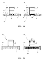
- the left and right photographs in FIG. 1 show FLM3D from Thermo, and FLM3D has a detector size thereof 600 cm 2 . Further, such a product is used for measuring a floor surface within a radiation controlled area, or is used for measuring alpha rays and beta rays on a wide range of sites, such as when a nuclear plant is dismantled.
- a detection area of a detector that has a size of 600 cm 2 (width of 30 cm ⁇ length of 20 cm) as illustrated in FIG. 1B , the same detection signal regardless of the location of the radionuclide (1 to 5 in FIG. 1B ) is generated. Therefore, in order to find a detailed contamination location, it is necessary to re-measure the detection area with a detector having a small detection area.
- an objective of the present disclosure is to provide a large-area radioactive surface contamination measurement device capable of simultaneously increasing speed, efficiency, and accuracy of measurement by enabling accurate observation of a radioactive contamination location even when a large-area is scanned in a short time.
- a large-area radioactive surface contamination measurement device including: a frame body 10 with a plurality of holes formed; a mover 20 connected to the frame body 10 to move the frame body 10; a plurality of radiation detection modules 30a and 30b each seated in the plurality of holes to detect any one or two or more of alpha rays, beta rays, and gamma rays; and a control unit for calculating a radioactive contamination location and a radioactive contamination level by comparing detection values of the plurality of radiation detection modules 30a and 30b with each other.
- the plurality of holes may be formed side by side at equal intervals.
- both the frame body 10 and the mover 20 may be mounted with casters in their lower portion, and a direction in which the plurality of holes are formed side by side may be perpendicular to a direction in which the frame body 10 and the mover 20 are connected to each other.
- each of the plurality of radiation detection modules may include: counters 31a and 31b seated in each of the plurality of holes; photomultiplier tubes 32a and 32b coupled to the counters 31a and 31b; and channel units 34, 35, and 36 mounted on the photomultiplier tubes 32a and 32b, wherein seating wings 33a and 33b are formed to extend horizontally from sides of the counters 31a and 31b so as to be seated on a perimeter of each of the plurality of holes.
- one or two channel units 34, 35, and 36 may be mounted on one photomultiplier tube 32a and 32b, and each of the two channel units 34, 35, and 36 may be configured to detect radioactivity different from each other.
- the control unit receiving detection information in real time from the plurality of radiation detection modules 30a and 30b to determine whether an area is radioactively contaminated may be further included, and the control unit may be provided with a computing mechanism to perform an algorithm assigning an identifier to each of the plurality of radiation detection modules 30a and 30b, computing a detection value periodically received from each identifier and a speed value of the plurality of radiation detection modules 30a and 30b moved by the mover 20, and deriving a radioactive detection map in real time on an area formed of a movement trajectory of the frame body 10.
- the large-area radioactive surface contamination measurement device of the present disclosure since the accurate observation of the radioactive contamination location can be realized even when the large-area is scanned in a short time, there is an effect that rapidness in speed, efficiency, and accuracy of the measurement is increased simultaneously.
- a large-area radioactive surface contamination measurement device includes a frame body 10, a mover 20, a plurality of radiation detection modules 30a and 30b, and a control unit for calculating a location and a level of radioactive contamination by comparing detection values of the plurality of radiation detectors with each other.
- a plurality of holes (not illustrated) is formed such that the plurality of radiation detection modules 30a and 30b can be mounted in the plurality of holes.
- a form in which the plurality of radiation detection modules 30a and 30b are provided and are simultaneously mounted in one frame body 10 so that the plurality of radiation detection modules 30a and 30b is capable of being moved integrally is configured. Therefore, a radioactive surface contamination measurement of an area equal to or larger than an area measured by the conventional large-area radioactive surface contamination measurement device can be measured, and the plurality of radiation detection modules 30a and 30b can respectively perform the measurement, so that a large-area radioactive surface contamination measurement device capable of searching a 'hot spot' that is a location most intensively radioactively contaminated is proposed.
- the plurality of radiation detection modules 30a and 30b respectively mounted in the frame body 10 is configured to detect one or more alpha rays, beta rays, and gamma rays.
- the plurality of radiation detection modules 30a and 30b respectively mounted in the frame body 10 is configured to detect one or more alpha rays, beta rays, and gamma rays.
- an alpha ray and beta ray detection module 30a and a gamma rays detection module 30b are illustrated.
- Conventionally used radiation detectors are used as the radiation detection modules 30a and 30b, but is manufactured to be respectively inserted in the plurality of holes (not illustrated) that is formed in the frame body 10.
- a Phoswich detector that can measure both alpha rays and beta rays may be manufactured in a form of a module.
- a NaI detector that can measure gamma rays may be manufactured in a form of a module.
- FIG. 2B a left side view illustrates a state in which the plurality of radiation detection modules 30a and 30b is mounted. Further, although the plurality of holes formed in the frame body 10 such that the plurality of radiation detection modules 30a and 30b can be respectively mounted therein is not seen, the plurality of radiation detection modules 30a and 30b is respectively mounted in the plurality of holes.
- the plurality of holes is formed side by side at equal intervals. Therefore, the plurality of radiation detection modules 30a and 30b detects a presence of a radioactive contaminant source on the basis of differential values according to a distance from the radioactive contaminant source, so that an accurate location and an accurate level of the radioactive contaminant source can be identified by a combination of differential detection values according to a relative location between the radioactive contaminant source and each of the plurality of the radiation detection modules 30a and 30b.
- the mover 20 is connected to the frame body 10 such that frame body 10 can be moved. More specifically, referring to FIGS. 2A and 2B , the mover 20 may be configured of a tow handle 21, a balance plate 22, and tow casters 23. At this time, the tow casters 23 are attached to a bottom surface of the balance plate 22 and a bottom surface of the frame body 10, thereby increasing mobility.
- the plurality of holes formed in the frame body 10 or the plurality of radiation detection modules 30a and 30b mounted in the plurality of holes does not need to be formed as a plurality of columns, but can be formed as only one column.
- the frame body 10 can be moved forward and backward due to the mover 20. Therefore, in a process of moving the frame body 10, an entire area of the surface formed along a movement trajectory of the frame body 10 is detected, so that the radiation detection modules 30a and 30b do not need to be mounted as a plurality of arrays. Further, even if the radiation detection modules 30a and 30b are mounted as one array, the same effect as when the radiation detection modules 30a and 30b are mounted as the plurality of arrays can be realized.
- the plurality of radiation detection modules 30a and 30b is respectively formed of a counters 31a and 31b seated in the plurality of holes, photomultiplier tubes 32a and 32b coupled to the counters 31a and 31b, and channel units 34, 35, and 36 mounted on the photomultiplier tubes 32a and 3b.
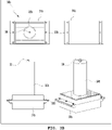
- a plan view, a bottom view, a perspective view, a front view are illustrated in clockwise order from the upper left.
- Two channel units 34 and 35 mounted on the radiation detector in FIG. 3A are an alpha rays channel unit 34 and a beta rays channel unit 35, respectively.
- a detector that can detect both alpha rays and beta rays is a phoswich detector as a representative example, and any other radiation detector that can detect both alpha rays and beta rays can be employed.
- a NaI detector or any other detector that can detect gamma rays can be employed.
- Both the detectors in FIGS. 3A and 3B have seating wings 33a and 33b on side surfaces of the counters 31a and 31b, respectively, and are be formed such that both the detectors can be placed on the plurality of holes (not illustrated) that is formed in the frame body 10.
- the seating wings 33a and 33b are provided with steps facing downward. Further, the steps are placed on an upper portion of a perimeter of the plurality of holes, respectively, and a lower portion of the steps are inserted into the respective holes. Therefore, the seating wings 33a and 33b may be very easily inserted into and pulled out from the respective holes.
- a height adjustment switch 12 that can adjust a height of the radiation detector is provided on the frame body 10. Therefore, when a surface height is uneven, an installation height of the radiation detection modules 30a and 30b can be adjusted instantly, so that a uniform investigation value may be obtained.
- control unit which receives detection information from the plurality of radiation detection modules 30a and 30b in real time and which identifies whether an area is radioactively contaminated may be further mounted.
- the control unit has a computing mechanism to perform an algorithm which assigns identifiers to each of the plurality of radiation detection modules 30a and 30b, computes a detection value periodically received from each of the identifiers and a speed value of the plurality of radiation detection modules 30a and 30b moved by the mover 20, and derives a radioactive detection map in real time on an area formed of the movement trajectory of the frame body 10.
- a time passed for each part and a tow speed for each part are variables, and the identifiers are respectively assigned to the radiation detection modules 30a and 30b. Therefore, in the entire area that is investigated, a radiation detection value may be obtained in units of a grid area equal to a size of one of the radiation detection modules 30a and 30b, so that a detection map in which the degree of detection of radioactivity may be determined over the entire investigated area is finally obtained. Therefore, an accurate location of contaminated surface can be identified, so that the hot spot can be accurately identified.
Landscapes
- Physics & Mathematics (AREA)
- Health & Medical Sciences (AREA)
- Life Sciences & Earth Sciences (AREA)
- General Physics & Mathematics (AREA)
- High Energy & Nuclear Physics (AREA)
- Molecular Biology (AREA)
- Spectroscopy & Molecular Physics (AREA)
- Measurement Of Radiation (AREA)
Applications Claiming Priority (2)
| Application Number | Priority Date | Filing Date | Title |
|---|---|---|---|
| KR1020200001145A KR102140038B1 (ko) | 2020-01-06 | 2020-01-06 | 복수개의 검출기를 이용한 대면적 방사능 표면오염 측정장치 |
| PCT/KR2020/018119 WO2021141256A1 (ko) | 2020-01-06 | 2020-12-11 | 복수개의 검출기를 이용한 대면적 방사능 표면오염 측정장치 |
Publications (3)
| Publication Number | Publication Date |
|---|---|
| EP4089445A1 true EP4089445A1 (de) | 2022-11-16 |
| EP4089445A4 EP4089445A4 (de) | 2024-01-17 |
| EP4089445B1 EP4089445B1 (de) | 2026-04-15 |
Family
ID=71834899
Family Applications (1)
| Application Number | Title | Priority Date | Filing Date |
|---|---|---|---|
| EP20911647.4A Active EP4089445B1 (de) | 2020-01-06 | 2020-12-11 | Grossflächige radioaktive oberflächenkontaminationsmessvorrichtung mit mehreren detektoren |
Country Status (5)
| Country | Link |
|---|---|
| US (1) | US11867851B2 (de) |
| EP (1) | EP4089445B1 (de) |
| JP (1) | JP7310026B2 (de) |
| KR (1) | KR102140038B1 (de) |
| WO (1) | WO2021141256A1 (de) |
Families Citing this family (3)
| Publication number | Priority date | Publication date | Assignee | Title |
|---|---|---|---|---|
| KR102140038B1 (ko) | 2020-01-06 | 2020-07-31 | 한국수력원자력 주식회사 | 복수개의 검출기를 이용한 대면적 방사능 표면오염 측정장치 |
| KR102343484B1 (ko) * | 2021-04-09 | 2021-12-27 | 윤철진 | 대면적 방사능 표면오염 및 방사선량 측정장치 |
| CN116224410B (zh) * | 2023-01-06 | 2025-08-26 | 兰州大学 | 一种适用于多辐射环境的甄别测量探测器 |
Family Cites Families (11)
| Publication number | Priority date | Publication date | Assignee | Title |
|---|---|---|---|---|
| JP2001249179A (ja) | 2000-03-06 | 2001-09-14 | Nuclear Fuel Ind Ltd | 放射線検出装置 |
| KR20110117325A (ko) * | 2010-04-21 | 2011-10-27 | 한국원자력연구원 | 지리정보동조형 방사선 분포 모니터링 시스템 및 방사선 분포 모니터링 방법 |
| KR101431709B1 (ko) * | 2012-12-11 | 2014-09-22 | (주)헤스코 | 측정대상 방사능핵종을 선택측정하는 이동식 방사능핵종 측정기 |
| KR101419766B1 (ko) | 2013-06-17 | 2014-07-21 | 동국대학교 경주캠퍼스 산학협력단 | 토양의 방사성 오염도 측정을 위한 휴대용 대면적 서베이미터 |
| JP6285276B2 (ja) * | 2014-05-15 | 2018-02-28 | 国立研究開発法人農業・食品産業技術総合研究機構 | 地表の放射線計測装置とその装置を用いた放射線計測方法 |
| CN108562925A (zh) * | 2018-03-07 | 2018-09-21 | 中国核电工程有限公司 | 一种MOX核燃料棒表面α污染的在线检测装置和方法 |
| JP6519070B1 (ja) * | 2018-03-09 | 2019-05-29 | 株式会社スリー・アール | 放射性物質による汚染の検査装置、検査方法 |
| KR102115847B1 (ko) * | 2018-06-14 | 2020-05-27 | (주)로드피아 | 방사선(능) 오염 탐지장치 |
| JP6512650B1 (ja) * | 2018-09-20 | 2019-05-15 | 株式会社スリー・アール | β線測定装置 |
| JP6519902B1 (ja) * | 2018-11-01 | 2019-05-29 | 株式会社スリー・アール | 使用済み容器の表面汚染の検査装置及び方法 |
| KR102140038B1 (ko) | 2020-01-06 | 2020-07-31 | 한국수력원자력 주식회사 | 복수개의 검출기를 이용한 대면적 방사능 표면오염 측정장치 |
-
2020
- 2020-01-06 KR KR1020200001145A patent/KR102140038B1/ko active Active
- 2020-12-11 EP EP20911647.4A patent/EP4089445B1/de active Active
- 2020-12-11 JP JP2022539363A patent/JP7310026B2/ja active Active
- 2020-12-11 US US17/789,421 patent/US11867851B2/en active Active
- 2020-12-11 WO PCT/KR2020/018119 patent/WO2021141256A1/ko not_active Ceased
Also Published As
| Publication number | Publication date |
|---|---|
| WO2021141256A1 (ko) | 2021-07-15 |
| US20230035596A1 (en) | 2023-02-02 |
| JP7310026B2 (ja) | 2023-07-18 |
| EP4089445B1 (de) | 2026-04-15 |
| JP2023508694A (ja) | 2023-03-03 |
| KR102140038B1 (ko) | 2020-07-31 |
| EP4089445A4 (de) | 2024-01-17 |
| US11867851B2 (en) | 2024-01-09 |
Similar Documents
| Publication | Publication Date | Title |
|---|---|---|
| US11867851B2 (en) | Large-area radioactive surface contamination measurement device using plurality of detectors | |
| US20160084974A1 (en) | Apparatus and method for the evaluation of gamma radiation events | |
| CA1219086A (en) | Radiation imaging apparatus | |
| JP2007529751A (ja) | 一次元配列3−d位置感受性イオン化検出器 | |
| US9734603B2 (en) | Systems and methods for peak tracking and gain adjustment | |
| US11543545B2 (en) | Method and apparatus to use a broad-spectrum energy source to correct a nonlinear energy response of a gamma-ray detector | |
| US6429434B1 (en) | Transmission attenuation correction method for PET and SPECT | |
| US7193208B1 (en) | Time-of-flight capable high resolution pet detector | |
| CN112470039B (zh) | 用于通过伽马辐射探测进行成像的系统和方法 | |
| Vaquero et al. | Performance characteristics of a compact position-sensitive LSO detector module | |
| Pani et al. | A Novel Method for $\gamma-\text {photons} $ Depth-of-Interaction Detection in Monolithic Scintillation Crystals | |
| Kim et al. | Position-sensitive NaI (TL) detector module for large-area Compton camera | |
| JP6301386B2 (ja) | 放射能汚染検査装置 | |
| EP3674752A1 (de) | Detektorsystem und strahlungsbildgebungsvorrichtung | |
| CN110012673A (zh) | 用于光谱分析和增益调整的系统和方法 | |
| Lee et al. | Positioning method for a radiation source using radiation spectroscopy detectors | |
| JPH09101371A (ja) | ガンマ線検出方法及び検出装置 | |
| US9508165B1 (en) | Systems and methods for peak tracking and gain adjustment | |
| JP2023048575A (ja) | 放射能測定装置と放射能測定方法 | |
| KR102343484B1 (ko) | 대면적 방사능 표면오염 및 방사선량 측정장치 | |
| US20190146099A1 (en) | Method to Reduce the Number of Signals to be Read Out in a Detector | |
| US20240151861A1 (en) | Scintigraphic detection device with a high degree of compactness and simplified electronics | |
| Mendes et al. | Evaluation of monolithic detector blocks for high-sensitivity PET imaging of the human brain | |
| KR102382482B1 (ko) | 방사선의 검출을 이용한 검사 장치 | |
| EP4488723A1 (de) | Pet-vorrichtung und kalibrierverfahren |
Legal Events
| Date | Code | Title | Description |
|---|---|---|---|
| STAA | Information on the status of an ep patent application or granted ep patent |
Free format text: STATUS: THE INTERNATIONAL PUBLICATION HAS BEEN MADE |
|
| PUAI | Public reference made under article 153(3) epc to a published international application that has entered the european phase |
Free format text: ORIGINAL CODE: 0009012 |
|
| STAA | Information on the status of an ep patent application or granted ep patent |
Free format text: STATUS: REQUEST FOR EXAMINATION WAS MADE |
|
| 17P | Request for examination filed |
Effective date: 20220720 |
|
| AK | Designated contracting states |
Kind code of ref document: A1 Designated state(s): AL AT BE BG CH CY CZ DE DK EE ES FI FR GB GR HR HU IE IS IT LI LT LU LV MC MK MT NL NO PL PT RO RS SE SI SK SM TR |
|
| DAV | Request for validation of the european patent (deleted) | ||
| DAX | Request for extension of the european patent (deleted) | ||
| REG | Reference to a national code |
Ref country code: DE Ref legal event code: R079 Ipc: G01T0001169000 Ref country code: DE Ref legal event code: R079 Ref document number: 602020070573 Country of ref document: DE Free format text: PREVIOUS MAIN CLASS: G01T0001167000 Ipc: G01T0001169000 |
|
| A4 | Supplementary search report drawn up and despatched |
Effective date: 20231214 |
|
| RIC1 | Information provided on ipc code assigned before grant |
Ipc: G01T 7/00 20060101ALI20231208BHEP Ipc: G01T 1/169 20060101AFI20231208BHEP |
|
| GRAP | Despatch of communication of intention to grant a patent |
Free format text: ORIGINAL CODE: EPIDOSNIGR1 |
|
| STAA | Information on the status of an ep patent application or granted ep patent |
Free format text: STATUS: GRANT OF PATENT IS INTENDED |
|
| INTG | Intention to grant announced |
Effective date: 20251017 |
|
| GRAS | Grant fee paid |
Free format text: ORIGINAL CODE: EPIDOSNIGR3 |
|
| GRAJ | Information related to disapproval of communication of intention to grant by the applicant or resumption of examination proceedings by the epo deleted |
Free format text: ORIGINAL CODE: EPIDOSDIGR1 |
|
| GRAL | Information related to payment of fee for publishing/printing deleted |
Free format text: ORIGINAL CODE: EPIDOSDIGR3 |
|
| STAA | Information on the status of an ep patent application or granted ep patent |
Free format text: STATUS: REQUEST FOR EXAMINATION WAS MADE |
|
| GRAP | Despatch of communication of intention to grant a patent |
Free format text: ORIGINAL CODE: EPIDOSNIGR1 |
|
| STAA | Information on the status of an ep patent application or granted ep patent |
Free format text: STATUS: GRANT OF PATENT IS INTENDED |
|
| INTC | Intention to grant announced (deleted) | ||
| GRAA | (expected) grant |
Free format text: ORIGINAL CODE: 0009210 |
|
| STAA | Information on the status of an ep patent application or granted ep patent |
Free format text: STATUS: THE PATENT HAS BEEN GRANTED |
|
| INTG | Intention to grant announced |
Effective date: 20260217 |
|
| AK | Designated contracting states |
Kind code of ref document: B1 Designated state(s): AL AT BE BG CH CY CZ DE DK EE ES FI FR GB GR HR HU IE IS IT LI LT LU LV MC MK MT NL NO PL PT RO RS SE SI SK SM TR |
|
| REG | Reference to a national code |
Ref country code: CH Ref legal event code: F10 Free format text: ST27 STATUS EVENT CODE: U-0-0-F10-F00 (AS PROVIDED BY THE NATIONAL OFFICE) Effective date: 20260415 |