EP4089402A1 - Method for inspecting welding quality of welded portion between electrode tab and lead - Google Patents
Method for inspecting welding quality of welded portion between electrode tab and lead Download PDFInfo
- Publication number
- EP4089402A1 EP4089402A1 EP21866956.2A EP21866956A EP4089402A1 EP 4089402 A1 EP4089402 A1 EP 4089402A1 EP 21866956 A EP21866956 A EP 21866956A EP 4089402 A1 EP4089402 A1 EP 4089402A1
- Authority
- EP
- European Patent Office
- Prior art keywords
- welding
- welded
- welded portion
- measuring
- traces
- Prior art date
- Legal status (The legal status is an assumption and is not a legal conclusion. Google has not performed a legal analysis and makes no representation as to the accuracy of the status listed.)
- Granted
Links
Images


Classifications
-
- G—PHYSICS
- G01—MEASURING; TESTING
- G01N—INVESTIGATING OR ANALYSING MATERIALS BY DETERMINING THEIR CHEMICAL OR PHYSICAL PROPERTIES
- G01N21/00—Investigating or analysing materials by the use of optical means, i.e. using sub-millimetre waves, infrared, visible or ultraviolet light
- G01N21/84—Systems specially adapted for particular applications
- G01N21/88—Investigating the presence of flaws or contamination
- G01N21/8851—Scan or image signal processing specially adapted therefor, e.g. for scan signal adjustment, for detecting different kinds of defects, for compensating for structures, markings, edges
-
- G—PHYSICS
- G01—MEASURING; TESTING
- G01B—MEASURING LENGTH, THICKNESS OR SIMILAR LINEAR DIMENSIONS; MEASURING ANGLES; MEASURING AREAS; MEASURING IRREGULARITIES OF SURFACES OR CONTOURS
- G01B5/00—Measuring arrangements characterised by the use of mechanical techniques
- G01B5/0037—Measuring of dimensions of welds
-
- B—PERFORMING OPERATIONS; TRANSPORTING
- B23—MACHINE TOOLS; METAL-WORKING NOT OTHERWISE PROVIDED FOR
- B23K—SOLDERING OR UNSOLDERING; WELDING; CLADDING OR PLATING BY SOLDERING OR WELDING; CUTTING BY APPLYING HEAT LOCALLY, e.g. FLAME CUTTING; WORKING BY LASER BEAM
- B23K20/00—Non-electric welding by applying impact or other pressure, with or without the application of heat, e.g. cladding or plating
- B23K20/10—Non-electric welding by applying impact or other pressure, with or without the application of heat, e.g. cladding or plating making use of vibrations, e.g. ultrasonic welding
-
- B—PERFORMING OPERATIONS; TRANSPORTING
- B23—MACHINE TOOLS; METAL-WORKING NOT OTHERWISE PROVIDED FOR
- B23K—SOLDERING OR UNSOLDERING; WELDING; CLADDING OR PLATING BY SOLDERING OR WELDING; CUTTING BY APPLYING HEAT LOCALLY, e.g. FLAME CUTTING; WORKING BY LASER BEAM
- B23K26/00—Working by laser beam, e.g. welding, cutting or boring
- B23K26/20—Bonding
- B23K26/21—Bonding by welding
-
- B—PERFORMING OPERATIONS; TRANSPORTING
- B23—MACHINE TOOLS; METAL-WORKING NOT OTHERWISE PROVIDED FOR
- B23K—SOLDERING OR UNSOLDERING; WELDING; CLADDING OR PLATING BY SOLDERING OR WELDING; CUTTING BY APPLYING HEAT LOCALLY, e.g. FLAME CUTTING; WORKING BY LASER BEAM
- B23K31/00—Processes relevant to this subclass, specially adapted for particular articles or purposes, but not covered by any single one of main groups B23K1/00 - B23K28/00
- B23K31/12—Processes relevant to this subclass, specially adapted for particular articles or purposes, but not covered by any single one of main groups B23K1/00 - B23K28/00 relating to investigating the properties, e.g. the weldability, of materials
- B23K31/125—Weld quality monitoring
-
- G—PHYSICS
- G01—MEASURING; TESTING
- G01B—MEASURING LENGTH, THICKNESS OR SIMILAR LINEAR DIMENSIONS; MEASURING ANGLES; MEASURING AREAS; MEASURING IRREGULARITIES OF SURFACES OR CONTOURS
- G01B11/00—Measuring arrangements characterised by the use of optical techniques
- G01B11/02—Measuring arrangements characterised by the use of optical techniques for measuring length, width or thickness
- G01B11/04—Measuring arrangements characterised by the use of optical techniques for measuring length, width or thickness specially adapted for measuring length or width of objects while moving
-
- G—PHYSICS
- G01—MEASURING; TESTING
- G01B—MEASURING LENGTH, THICKNESS OR SIMILAR LINEAR DIMENSIONS; MEASURING ANGLES; MEASURING AREAS; MEASURING IRREGULARITIES OF SURFACES OR CONTOURS
- G01B11/00—Measuring arrangements characterised by the use of optical techniques
- G01B11/28—Measuring arrangements characterised by the use of optical techniques for measuring areas
-
- G—PHYSICS
- G01—MEASURING; TESTING
- G01N—INVESTIGATING OR ANALYSING MATERIALS BY DETERMINING THEIR CHEMICAL OR PHYSICAL PROPERTIES
- G01N21/00—Investigating or analysing materials by the use of optical means, i.e. using sub-millimetre waves, infrared, visible or ultraviolet light
- G01N21/84—Systems specially adapted for particular applications
- G01N21/88—Investigating the presence of flaws or contamination
- G01N21/95—Investigating the presence of flaws or contamination characterised by the material or shape of the object to be examined
-
- G—PHYSICS
- G01—MEASURING; TESTING
- G01N—INVESTIGATING OR ANALYSING MATERIALS BY DETERMINING THEIR CHEMICAL OR PHYSICAL PROPERTIES
- G01N33/00—Investigating or analysing materials by specific methods not covered by groups G01N1/00 - G01N31/00
- G01N33/20—Metals
- G01N33/207—Welded or soldered joints; Solderability
-
- G—PHYSICS
- G06—COMPUTING OR CALCULATING; COUNTING
- G06T—IMAGE DATA PROCESSING OR GENERATION, IN GENERAL
- G06T7/00—Image analysis
- G06T7/0002—Inspection of images, e.g. flaw detection
- G06T7/0004—Industrial image inspection
- G06T7/0006—Industrial image inspection using a design-rule based approach
-
- B—PERFORMING OPERATIONS; TRANSPORTING
- B23—MACHINE TOOLS; METAL-WORKING NOT OTHERWISE PROVIDED FOR
- B23K—SOLDERING OR UNSOLDERING; WELDING; CLADDING OR PLATING BY SOLDERING OR WELDING; CUTTING BY APPLYING HEAT LOCALLY, e.g. FLAME CUTTING; WORKING BY LASER BEAM
- B23K2101/00—Articles made by soldering, welding or cutting
- B23K2101/36—Electric or electronic devices
- B23K2101/38—Conductors
-
- G—PHYSICS
- G01—MEASURING; TESTING
- G01N—INVESTIGATING OR ANALYSING MATERIALS BY DETERMINING THEIR CHEMICAL OR PHYSICAL PROPERTIES
- G01N21/00—Investigating or analysing materials by the use of optical means, i.e. using sub-millimetre waves, infrared, visible or ultraviolet light
- G01N21/84—Systems specially adapted for particular applications
- G01N21/88—Investigating the presence of flaws or contamination
- G01N21/8851—Scan or image signal processing specially adapted therefor, e.g. for scan signal adjustment, for detecting different kinds of defects, for compensating for structures, markings, edges
- G01N2021/8854—Grading and classifying of flaws
-
- G—PHYSICS
- G01—MEASURING; TESTING
- G01N—INVESTIGATING OR ANALYSING MATERIALS BY DETERMINING THEIR CHEMICAL OR PHYSICAL PROPERTIES
- G01N21/00—Investigating or analysing materials by the use of optical means, i.e. using sub-millimetre waves, infrared, visible or ultraviolet light
- G01N21/84—Systems specially adapted for particular applications
- G01N21/88—Investigating the presence of flaws or contamination
- G01N21/8851—Scan or image signal processing specially adapted therefor, e.g. for scan signal adjustment, for detecting different kinds of defects, for compensating for structures, markings, edges
- G01N2021/8887—Scan or image signal processing specially adapted therefor, e.g. for scan signal adjustment, for detecting different kinds of defects, for compensating for structures, markings, edges based on image processing techniques
-
- G—PHYSICS
- G06—COMPUTING OR CALCULATING; COUNTING
- G06T—IMAGE DATA PROCESSING OR GENERATION, IN GENERAL
- G06T2207/00—Indexing scheme for image analysis or image enhancement
- G06T2207/30—Subject of image; Context of image processing
- G06T2207/30108—Industrial image inspection
- G06T2207/30152—Solder
-
- H—ELECTRICITY
- H01—ELECTRIC ELEMENTS
- H01M—PROCESSES OR MEANS, e.g. BATTERIES, FOR THE DIRECT CONVERSION OF CHEMICAL ENERGY INTO ELECTRICAL ENERGY
- H01M50/00—Constructional details or processes of manufacture of the non-active parts of electrochemical cells other than fuel cells, e.g. hybrid cells
- H01M50/50—Current conducting connections for cells or batteries
- H01M50/531—Electrode connections inside a battery casing
- H01M50/536—Electrode connections inside a battery casing characterised by the method of fixing the leads to the electrodes, e.g. by welding
-
- Y—GENERAL TAGGING OF NEW TECHNOLOGICAL DEVELOPMENTS; GENERAL TAGGING OF CROSS-SECTIONAL TECHNOLOGIES SPANNING OVER SEVERAL SECTIONS OF THE IPC; TECHNICAL SUBJECTS COVERED BY FORMER USPC CROSS-REFERENCE ART COLLECTIONS [XRACs] AND DIGESTS
- Y02—TECHNOLOGIES OR APPLICATIONS FOR MITIGATION OR ADAPTATION AGAINST CLIMATE CHANGE
- Y02E—REDUCTION OF GREENHOUSE GAS [GHG] EMISSIONS, RELATED TO ENERGY GENERATION, TRANSMISSION OR DISTRIBUTION
- Y02E60/00—Enabling technologies; Technologies with a potential or indirect contribution to GHG emissions mitigation
- Y02E60/10—Energy storage using batteries
Definitions
- the present invention relates to a method of inspecting a welding quality for determining a welded portion of an electrode tab and an electrode lead has been weakly welded, excessively welded or normally welded.
- lithium secondary batteries which exhibit a high energy density and operational potential, a long cycle life, and a low self-discharge rate have been commercialized and widely used.
- the lithium secondary battery has a structure where a non-aqueous electrolyte containing a lithium salt is impregnated in an electrode assembly in which a porous separator is interposed between a positive electrode and a negative electrode where an active material has been applied on a current collector.
- Such a lithium secondary battery may be classified into a can-type secondary battery in which the cell assembly is embedded in a metal can, and a pouch-type secondary battery in which the cell assembly is embedded in a pouch case of an aluminum laminate sheet, depending on the shape of the exterior material case.
- Pouch-type lithium secondary batteries are drawing attention as the power source of electric vehicles or hybrid vehicles due to a low price, a high energy density, and advantage that it is easy to form a large capacity battery pack through serial or parallel connection.
- a pouch-type lithium secondary battery has a structure in which a cell assembly, to which a plate-type electrode lead is connected, is sealed together with an electrolyte solution in a pouch case. A part of the electrode lead is exposed to the outside of the pouch case, and the exposed electrode lead is electrically connected to a device where a secondary battery is mounted or is used to electrically connect secondary batteries.
- the pouch-type lithium secondary battery includes an electrode assembly, a plurality of electrode tabs extending from the electrode assembly, electrode leads welded to the electrode tabs, and a pouch-type exterior material accommodating the electrode assembly.
- Such electrode tabs are extended from each electrode plate of the electrode assembly, the electrode leads are electrically connected to the plurality of electrode tabs extended from respective electrode plates and are coupled in a form that is partly exposed to the outside of the pouch case.
- the ultrasonic welding is a scheme which generates ultrasonic vibrations of 10 to 75 kHz and welds metal through ultrasonic vibration friction heat between metals. Namely, if ultrasonic vibration is applied by the ultrasonic welding device in a state that the electrode tab contacts the electrode lead, friction heat is generated on the contact surface between the electrode tab and the electrode lead, and the electrode tab and the electrode lead are welded by the generated friction heat.
- the welding quality of the electrode tab-electrode lead welded portion was checked by measuring the tensile strength by pulling the electrode tab and the electrode lead by a gripper, respectively, but since this is a destructive inspection method, total inspection is impossible, and the welding quality can be checked by only an intermittent sample test.
- Korean Patent No. 10-1678662 discloses a technology for determining the welding quality by measuring welding points of an inspection area by vision and comparing the sum of the welding points with the welding strength.
- the inspection area is limited to some pressure points in the above-described technology, reliability decreases.
- a non-destructive inspection method capable of improving reliability of inspection in inspecting the welding quality of the electrode tab-electrode lead welded portion.
- the present invention has been made to solve the above problems, and an object of the present invention is to provide a method of inspecting a welding quality of an electrode tab-electrode lead welded portion of a pouch-type lithium secondary battery in a non-destructive manner.
- an object of the present invention is to provide an inspection method capable of determining the welding quality in a simplified method.
- a method of inspecting a welding quality includes: recognizing welding traces of the welded portion by a vision inspection device; measuring a size of each of the recognized welding traces; and determining whether the welded portion has been weakly welded, excessively welded or normally welded by comparing the measured size with a reference value.
- the measuring includes measuring a diagonal length of each of the welding traces.
- the welded portion may be welded by an ultrasonic welding or laser welding method.
- the recognizing may include vision-inspecting an electrode lead surface of the welded portion.
- the measuring may include measuring an area of each of the welding traces.
- the reference value may be obtained from welding quality correlation data according to a pitch of a welding horn.
- the determining may include determining that the welded portion has been weakly welded if an average value of sizes of the welding traces is smaller than the reference value and determining that the welded portion has been excessively welded if the average value is greater than the reference value.
- the measuring may include measuring sizes of remaining pressure points except for pressure points existing on a first line of each of an upper side, a lower side, a left side and a right side of the welded portion.
- the method includes inspecting a tensile strength of an object determined as having been normally welded during the determining.
- the welding quality can be measured in a simple method.
- the boundary of the welded portion can be clearly recognized, and the welding quality inspection can be more accurately performed.
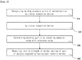
- FIG. 1 is a flowchart illustrating the order of a method of inspecting a welding quality according to an embodiment of the present invention.
- a method of inspecting a welding quality of the present invention is a method for inspecting a welding quality of an electrode tab-electrode lead welded portion of a pouch-type lithium secondary battery, and the method includes: recognizing welding traces of the welded portion by a vision inspection device (S10); measuring a size of each of the recognized welding traces (S20); and determining whether the welded portion has been weakly welded, excessively welded or normally welded by comparing the measured size with a reference value (S30).
- S10 vision inspection device
- S20 measuring a size of each of the recognized welding traces
- S30 determining whether the welded portion has been weakly welded, excessively welded or normally welded by comparing the measured size with a reference value
- the inventors of the present invention have devised the present invention of measuring the welding quality by measuring the size of the welding trace of the welded portion in view of the fact that the larger the welding strength of the welded portion, the larger the welding trace.
- the welding trace in the present invention is a concept including welding pressure points in the case of an ultrasonic welding method and welding beads in the case of a laser welding method.
- the vision inspection step (S10) includes recognizing welding traces of the welded portion, where the electrode tab and the electrode lead have been welded, by a vision inspection device.
- the vision inspection device may be a microscope or an imaging camera.
- FIG. 2 is a schematic diagram showing a vision inspection process for an ultrasonic welding portion according to an embodiment of the present invention.
- a vision inspection unit 210 may photograph or scan the welded portion and transmit image data or image files to a data input unit 220.
- the data input unit 220 may transmit data such as images, which are received from the vision inspection unit 210, to a measuring unit 230, and the measuring unit 230 may measure lengths of diagonal lines of pressure points from images, which are received form the data input unit 220, and/or areas of the pressure points, and transmit the measurement result information to a data storage unit (not shown), a display unit 250, or a determination unit 240.
- the determination unit 240 compares the lengths of diagonal lines of pressure points, which represent the sizes of the pressure points received from the measuring unit 230, and/or the areas of the pressure points, with the reference value, which becomes the basis for determining whether there is a welding defect, to thereby determine whether the welded portion has been weakly welded, excessively welded or normally welded.
- the inspection method of the present invention is characterized in performing vision inspection for the lead surface of the welded portion in the vision inspection step.
- the welding is performed in a state that the electrode tab is located under the electrode lead unlike the ultrasonic welding.
- the vision inspection unit vision-inspects the upper surface which is the electrode lead surface of the electrode lead welded portion.
- the sizes of the welding traces are measured from the image of the welded portion obtained by the vision inspection.
- the size of the pressure point may be the length of the diagonal line of the welding trace.
- FIG. 3 is a conceptual diagram showing sizes of welding traces. Referring to FIG. 3 , the welded portion includes a plurality of welding traces, and one welding trace has a form of rhombus. The size of the welding trace in a rhombus shape may be estimated by the length of the diagonal line (a, b) which is the distance between two vertexes facing each other.
- the size of the welding trace may be estimated by measuring the area of the welding trace.
- There may be various methods of measuring the area of the welding trace but in one preferred example, a method of measuring an image in pixel units may be used. By recognizing the number of pixels corresponding to the area occupied by the welding trace in the image, automation is possible, and uniform measurement criteria may be applied.
- the measuring step may be to measure the sizes of remaining pressure points except for pressure points existing on each first line of an upper side, a lower side, a left side and a right side of the welded portion in the image obtained at the vision inspection step.
- FIGS. 6 and 7 illustrate an image of a welded portion obtained from a vision inspection unit according to an embodiment of the present invention.
- FIG. 6 shows an image of a lead surface in a welded portion of a positive electrode tab and a lead
- FIG. 7 shows an image of a lead surface in a welded portion of a negative electrode tab and a lead.
- the measuring unit may measure the area and the length of the diagonal line (width, height) for a plurality of welding traces from the image and display their measurement values. Further, the sizes of all welding traces in the inspection area may be measured, but pressure points existing on each first line of an upper side, a lower side, a left side and a right side are not measured. Referring to FIG.
- sizes of pressure points existing on the first line of the upper portion are significantly smaller than sizes of other pressure points.
- sizes of pressure points existing on the first line of the inspection area are significantly smaller than sizes of other pressure points.
- the determining step (S30) is a step of determining whether there is a welding defect in the welded portion by comparing the area and the length of the diagonal line of the welding trace measured in the measuring step (S20) with the reference value.
- the determining step includes a process of setting a numerical value range of the sizes of welding traces, which satisfy normal welding requirements, to a reference value, based on welding quality result data according to sizes of welding traces in advance, and determining that the welded portion has been weakly welded if the numerical range is below the preset reference value, determining that the welded portion has been excessively welded if the numerical range is above the reference value, and determining that the welded portion has been normally welded if the numerical range corresponds to the reference value.
- the reference value may be obtained from welding quality correlation data according to a pitch of a welding horn.
- the welding horn refers to a member included in an ultrasonic welding device.
- the ultrasonic welding is to join objects by ultrasonic vibrations in a state that a welded object is inserted between horn and anvil welding bodies.
- the welding conditions may be determined by adjusting the pitch of the horn.
- the reference value may be set based on the horn pitch.
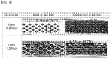
- FIG. 5 shows the result of setting a reference value according to the pitch of a horn and determining the welding quality according to the set reference value, according to an embodiment of the present invention.
- the reference value of the normal welding is in the range of 0.889 to 1.016 mm.
- the size of the welding trace is below the above numerical value range, it is determined as a weak welding, and when the size is above the above numerical value range, it is determined as an excessive welding.
- Even when the horn pitch is 1.2mm it is possible to determine whether the welding corresponds to a weak welding, an excessive welding or a normal welding, by setting a reference value.
- the method of determining the welding quality by comparing lengths of diagonal lines of welding traces is simpler than the method of determining the welding quality by comparing welded areas.
- FIG. 5 shows an example of determining whether there is a welding defect by measuring lengths of diagonal lines of welding traces, but it is also possible to determine whether there is a welding defect by measuring areas occupied by the welding traces.
- the welding quality can be determined by measuring the areas and lengths of respective diagonal lines of the welding traces, calculating the average value of the measured values, and comparing the average value with the reference value.
- FIG. 4 is a flowchart illustrating the order of a method of inspecting a welding quality according to another embodiment of the present invention.
- the welding strength is estimated form the size of the welding trace, and thus the welding may be regarded as a normal welding even when it actually is a weak welding.
- a tensile strength inspection is additionally performed.
- the tensile strength inspection is a destructive inspection in which the welded portion is broken, it is not possible to perform inspection for all objects which are determined as being normal, and the inspection is intermittently performed for a few objects. Since the inspection method of the present invention includes the above-described non-destructive inspection for all battery cells, it can supplement intermittent tensile strength inspection.
- the battery which is inspected by the inspection method of the present invention, may have a structure in which an electrode assembly having a structure, where a positive electrode, a separator, and a negative electrode are alternately stacked, is accommodated in a battery case.
- the positive electrode and the negative electrode each have a structure where an electrode slurry containing an electrode active material is applied on a current collector, which was then dried and rolled to thereby form an active material layer.
- an electrolyte solution may be injected into the inside and be sealed to thereby manufacture a battery cell.
- the current collector may be a positive electrode current collector or a negative electrode current collector
- the electrode active material may be a positive electrode active material or a negative electrode active material
- the electrode slurry may further include a conductive material and a binder in addition to the electrode active material.
- the positive electrode collector generally has a thickness of 3 to 500 micrometers.
- the positive electrode current collector is not particularly limited as long as it has high conductivity without causing a chemical change in the battery.
- Examples of the positive electrode current collector include stainless steel, aluminum, nickel, titanium, sintered carbon or aluminum or stainless steel of which the surface has been treated with carbon, nickel, titanium, silver, or the like.
- the current collector may have fine irregularities on the surface thereof to increase the adhesion of the positive electrode active material, and various forms such as a film, a sheet, a foil, a net, a porous body, a foam, and a nonwoven fabric are possible.
- the sheet for the negative electrode collector generally has a thickness of 3 to 500 micrometers.
- the negative electrode current collector is not particularly limited as long as it has electrical conductivity without causing chemical changes in the battery, and examples thereof include copper, stainless steel, aluminum, nickel, titanium, sintered carbon, copper or stainless steel of which the surface has been treated with carbon, nickel, titanium, silver or the like, aluminum-cadmium alloy, or the like.
- fine unevenness can be formed on the surface to enhance the bonding force of the negative electrode active material, and it can be used in various forms such as a film, a sheet, a foil, a net, a porous body, a foam, and a nonwoven fabric.
- the positive electrode active material is a material capable of causing an electrochemical reaction and a lithium transition metal oxide, and contains two or more transition metals.
- the negative electrode active material examples include carbon such as nongraphitized carbon and graphite carbon; metal complex oxide such as Li x Fe 2 O 3 (0 ⁇ x ⁇ 1), Li x WO 2 (0 ⁇ x ⁇ 1), Sn x Me 1-x Me' y O z (Me: Mn, Fe, Pb, Ge; Me': Al, B, P, Si, groups 1, 2, and 3 of the periodic table, halogen; 0 ⁇ x ⁇ 1; 1 ⁇ y ⁇ 3; 1 ⁇ z ⁇ 8); lithium metal; lithium alloy; silicon alloy; tin alloy; metal oxides such as SnO, SnO 2 , PbO, PbO 2 , Pb 2 O 3 , Pb 3 O 4 , Sb 2 O 3 , Sb 2 O 4 , Sb 2 O 5 , GeO, GeO 2 , Bi 2 O 3 , Bi 2 O 4 , and Bi 2 O 5 ; conductive polymers such as polyacetylene; and Li-Co-Ni-based materials.
- metal complex oxide such as
- the conductive material is usually added in an amount of 1 to 30% by weight based on the total weight of the mixture including the positive electrode active material.
- a conductive material is not particularly limited as long as it has electrical conductivity without causing a chemical change in the battery, and examples thereof include graphite such as natural graphite and artificial graphite; carbon black such as carbon black, acetylene black, Ketjen black, channel black, furnace black, lamp black, and summer black; conductive fibers such as carbon fiber and metal fiber; metal powders such as carbon fluoride, aluminum and nickel powder; conductive whiskey such as zinc oxide and potassium titanate; conductive metal oxides such as titanium oxide; and conductive materials such as polyphenylene derivatives and the like.
- the binder is added in an amount of 1 to 30% by weight, on the basis of the total weight of the mixture containing the positive electrode active material, as a component that assists in bonding between the active material and the conductive material and bonding to the current collector.
- binders include polyvinylidene fluoride, polyvinyl alcohol, carboxymethylcellulose (CMC), starch, hydroxypropylcellulose, regenerated cellulose, polyvinylpyrrolidone, tetrafluoroethylene, polyethylene, polypropylene, ethyl ene-propylene-diene terpolymer (EPDM), sulfonated EPDM, styrene butylene rubber, fluorine rubber, various copolymers and the like.
- the separator is interposed between the positive electrode and the negative electrode, and an insulating thin film having high ion permeability and mechanical strength is used.
- the pore diameter of the separator is generally 0.01 to 10 micrometers, and the thickness is generally 5 to 300 micrometers.
- Examples of such a separator include olefin-based polymers such as polypropylene which is chemically resistant and hydrophobic; a sheet or a nonwoven fabric made of glass fiber, polyethylene or the like.
- an electrode tab is formed at one side of an electrode, and the electrode tab may be a positive electrode tab or a negative electrode tab.
- a positive electrode lead and a negative electrode lead are connected to the positive electrode tab and the negative electrode tab, respectively.
- the positive electrode lead and the negative electrode lead are drawn to the outside to thereby play a role of a terminal which is electrically connected to the outside.
- the positive electrode lead and the negative electrode lead may be joined to the positive electrode tab and the negative electrode tab, respectively, by welding.
- the battery case is not particularly limited as long as it is used as an exterior material for packaging the battery, and a cylindrical, square, or pouch type may be used and specifically a pouch-type battery case may be used.
- the pouch-type battery case is generally made of an aluminum laminate sheet and may be composed of an inner sealant layer for sealing, a metal layer for preventing permeation of materials, and an external resin layer forming the outermost part of the case. Details of the battery case are known to those of ordinary skill in the art, and thus detailed description thereof will be omitted.
- an electrode tab is drawn out to one side for electric connection with an external device or another battery cell.
- the electrode tab may be a positive electrode tab or a negative electrode tab, and the positive electrode tab and the negative electrode tab may be coupled by the welding with the electrode lead.
- the electrode lead is drawn to the outside of the battery case.
Landscapes
- Engineering & Computer Science (AREA)
- Physics & Mathematics (AREA)
- General Physics & Mathematics (AREA)
- Life Sciences & Earth Sciences (AREA)
- Chemical & Material Sciences (AREA)
- Health & Medical Sciences (AREA)
- General Health & Medical Sciences (AREA)
- Analytical Chemistry (AREA)
- Biochemistry (AREA)
- Immunology (AREA)
- Pathology (AREA)
- Mechanical Engineering (AREA)
- Quality & Reliability (AREA)
- Computer Vision & Pattern Recognition (AREA)
- Food Science & Technology (AREA)
- Medicinal Chemistry (AREA)
- Signal Processing (AREA)
- Optics & Photonics (AREA)
- Plasma & Fusion (AREA)
- Theoretical Computer Science (AREA)
- Connection Of Batteries Or Terminals (AREA)
Abstract
Description
- This application claims the benefit of priority based on
Korean Patent Application No. 10-2020-0116258, filed on September 10, 2020 - The present invention relates to a method of inspecting a welding quality for determining a welded portion of an electrode tab and an electrode lead has been weakly welded, excessively welded or normally welded.
- As technologies for mobile devices are developed and demand for the mobile devices increases, there has been a rapid increase in demand for secondary batteries as energy sources. Among such secondary batteries, lithium secondary batteries, which exhibit a high energy density and operational potential, a long cycle life, and a low self-discharge rate have been commercialized and widely used.
- The lithium secondary battery has a structure where a non-aqueous electrolyte containing a lithium salt is impregnated in an electrode assembly in which a porous separator is interposed between a positive electrode and a negative electrode where an active material has been applied on a current collector.
- Such a lithium secondary battery may be classified into a can-type secondary battery in which the cell assembly is embedded in a metal can, and a pouch-type secondary battery in which the cell assembly is embedded in a pouch case of an aluminum laminate sheet, depending on the shape of the exterior material case.
- Pouch-type lithium secondary batteries are drawing attention as the power source of electric vehicles or hybrid vehicles due to a low price, a high energy density, and advantage that it is easy to form a large capacity battery pack through serial or parallel connection. Such a pouch-type lithium secondary battery has a structure in which a cell assembly, to which a plate-type electrode lead is connected, is sealed together with an electrolyte solution in a pouch case. A part of the electrode lead is exposed to the outside of the pouch case, and the exposed electrode lead is electrically connected to a device where a secondary battery is mounted or is used to electrically connect secondary batteries.
- The pouch-type lithium secondary battery includes an electrode assembly, a plurality of electrode tabs extending from the electrode assembly, electrode leads welded to the electrode tabs, and a pouch-type exterior material accommodating the electrode assembly.
- Such electrode tabs are extended from each electrode plate of the electrode assembly, the electrode leads are electrically connected to the plurality of electrode tabs extended from respective electrode plates and are coupled in a form that is partly exposed to the outside of the pouch case.
- When the electrode tab and the electrode lead are welded, laser welding, resistance welding and ultrasonic welding may be used. Herein, the ultrasonic welding is a scheme which generates ultrasonic vibrations of 10 to 75 kHz and welds metal through ultrasonic vibration friction heat between metals. Namely, if ultrasonic vibration is applied by the ultrasonic welding device in a state that the electrode tab contacts the electrode lead, friction heat is generated on the contact surface between the electrode tab and the electrode lead, and the electrode tab and the electrode lead are welded by the generated friction heat.
- The welding quality of the electrode tab-electrode lead welded portion was checked by measuring the tensile strength by pulling the electrode tab and the electrode lead by a gripper, respectively, but since this is a destructive inspection method, total inspection is impossible, and the welding quality can be checked by only an intermittent sample test.
-
Korean Patent No. 10-1678662 - The present invention has been made to solve the above problems, and an object of the present invention is to provide a method of inspecting a welding quality of an electrode tab-electrode lead welded portion of a pouch-type lithium secondary battery in a non-destructive manner.
- Further, an object of the present invention is to provide an inspection method capable of determining the welding quality in a simplified method.
- A method of inspecting a welding quality according to an embodiment of the present invention includes: recognizing welding traces of the welded portion by a vision inspection device; measuring a size of each of the recognized welding traces; and determining whether the welded portion has been weakly welded, excessively welded or normally welded by comparing the measured size with a reference value.
- In an embodiment of the present invention, the measuring includes measuring a diagonal length of each of the welding traces.
- In an embodiment of the present invention, the welded portion may be welded by an ultrasonic welding or laser welding method.
- In an embodiment of the present invention, the recognizing may include vision-inspecting an electrode lead surface of the welded portion.
- In an embodiment of the present invention, the measuring may include measuring an area of each of the welding traces.
- In an embodiment of the present invention, the reference value may be obtained from welding quality correlation data according to a pitch of a welding horn.
- In an embodiment of the present invention, the determining may include determining that the welded portion has been weakly welded if an average value of sizes of the welding traces is smaller than the reference value and determining that the welded portion has been excessively welded if the average value is greater than the reference value.
- In an embodiment of the present invention, the measuring may include measuring sizes of remaining pressure points except for pressure points existing on a first line of each of an upper side, a lower side, a left side and a right side of the welded portion.
- In an embodiment of the present invention, the method includes inspecting a tensile strength of an object determined as having been normally welded during the determining.
- According to the present invention, since a welding quality is measured by comparing the measurement value of the length of the diagonal line of the welding trace of the welded portion with the reference value, the welding quality can be measured in a simple method.
- According to the present invention, since the lead surface of the welded portion is vision-inspected, the boundary of the welded portion can be clearly recognized, and the welding quality inspection can be more accurately performed.
-
-
FIG. 1 is a flowchart illustrating the order of a method of inspecting a welding quality according to an embodiment of the present invention. -
FIG. 2 is a schematic diagram showing a vision inspection process according to an embodiment of the present invention. -
FIG. 3 is a conceptual diagram showing sizes of welding traces. -
FIG. 4 is a flowchart illustrating the order of a method of inspecting a welding quality according to another embodiment of the present invention. -
FIGS. 5 to 7 are diagrams showing the results of vision-measuring sizes of welding traces according to an embodiment of the present invention. - Hereinafter, the present invention will be described in detail with reference to the drawings. The terms and words used in the present specification and claims should not be construed as limited to ordinary or dictionary terms and the inventor may properly define the concept of the terms in order to best describe its invention. The terms and words should be construed as meaning and concept consistent with the technical idea of the present invention.
- In this application, it should be understood that terms such as "include" or "have" are intended to indicate that there is a feature, number, step, operation, component, part, or a combination thereof described on the specification, and they do not exclude in advance the possibility of the presence or addition of one or more other features or numbers, steps, operations, components, parts or combinations thereof. Also, when a portion such as a layer, a film, an area, a plate, etc. is referred to as being "on" another portion, this includes not only the case where the portion is "directly on" the another portion but also the case where further another portion is interposed therebetween. On the other hand, when a portion such as a layer, a film, an area, a plate, etc. is referred to as being "under" another portion, this includes not only the case where the portion is "directly under" the another portion but also the case where further another portion is interposed therebetween. In addition, to be disposed "on" in the present application may include the case disposed at the bottom as well as the top.
- Hereinafter, the present invention will be described in detail with reference to the drawings.
-
FIG. 1 is a flowchart illustrating the order of a method of inspecting a welding quality according to an embodiment of the present invention. Referring toFIG. 1 , a method of inspecting a welding quality of the present invention is a method for inspecting a welding quality of an electrode tab-electrode lead welded portion of a pouch-type lithium secondary battery, and the method includes: recognizing welding traces of the welded portion by a vision inspection device (S10); measuring a size of each of the recognized welding traces (S20); and determining whether the welded portion has been weakly welded, excessively welded or normally welded by comparing the measured size with a reference value (S30). - The inventors of the present invention have devised the present invention of measuring the welding quality by measuring the size of the welding trace of the welded portion in view of the fact that the larger the welding strength of the welded portion, the larger the welding trace.
- The welding trace in the present invention is a concept including welding pressure points in the case of an ultrasonic welding method and welding beads in the case of a laser welding method.
- In the conventional welding quality inspection method, only the tensile strength was measured by pulling the electrode tab and the electrode lead by a gripper, respectively. However, since the battery is broken in this method, only intermittent inspection like a sample test was performed. However, according to the welding quality inspection method of the present invention, welding traces of the welded portion are vision-inspected, and the sizes of the welding traces recognized in the vision inspection are measured to thereby determine the welding quality. In this case, since the battery is not broken at the time of the welding quality inspection, all batteries can be inspected.
- The vision inspection step (S10) includes recognizing welding traces of the welded portion, where the electrode tab and the electrode lead have been welded, by a vision inspection device. The vision inspection device may be a microscope or an imaging camera.
-
FIG. 2 is a schematic diagram showing a vision inspection process for an ultrasonic welding portion according to an embodiment of the present invention. Referring toFIG. 2 , avision inspection unit 210 may photograph or scan the welded portion and transmit image data or image files to adata input unit 220. Thedata input unit 220 may transmit data such as images, which are received from thevision inspection unit 210, to ameasuring unit 230, and themeasuring unit 230 may measure lengths of diagonal lines of pressure points from images, which are received form thedata input unit 220, and/or areas of the pressure points, and transmit the measurement result information to a data storage unit (not shown), adisplay unit 250, or adetermination unit 240. Further, thedetermination unit 240 compares the lengths of diagonal lines of pressure points, which represent the sizes of the pressure points received from themeasuring unit 230, and/or the areas of the pressure points, with the reference value, which becomes the basis for determining whether there is a welding defect, to thereby determine whether the welded portion has been weakly welded, excessively welded or normally welded. - Referring to
FIG. 2 , in the case of ultrasonic welding, welding is performed in a state that anelectrode tab 120 is positioned on the upper portion of an electrode lead, and thevision inspection unit 210 vision-inspect the back surface, which is the electrode lead surface, among the top surface and the back surface of the welded portion of the electrode tab 100 and theelectrode lead 110. This is because the upper surface of the welded portion is an electrode tab surface, and the electrode tab is made of an electrode current collector foil, and thus the boundary of the welding trace is not clearly recognized at the time of vision inspection due to light reflex. On the contrary, the lead surface, which is the lower surface of the welded portion, does not have a problem that the boundary becomes unclear due to light reflex. As such, the inspection method of the present invention is characterized in performing vision inspection for the lead surface of the welded portion in the vision inspection step. - Further, in the case of the laser welding, the welding is performed in a state that the electrode tab is located under the electrode lead unlike the ultrasonic welding. As such, in this case, the vision inspection unit vision-inspects the upper surface which is the electrode lead surface of the electrode lead welded portion.
- In the measuring step (S20), the sizes of the welding traces are measured from the image of the welded portion obtained by the vision inspection. In one specific example, the size of the pressure point may be the length of the diagonal line of the welding trace.
FIG. 3 is a conceptual diagram showing sizes of welding traces. Referring toFIG. 3 , the welded portion includes a plurality of welding traces, and one welding trace has a form of rhombus. The size of the welding trace in a rhombus shape may be estimated by the length of the diagonal line (a, b) which is the distance between two vertexes facing each other. - In one specific example, the size of the welding trace may be estimated by measuring the area of the welding trace. There may be various methods of measuring the area of the welding trace, but in one preferred example, a method of measuring an image in pixel units may be used. By recognizing the number of pixels corresponding to the area occupied by the welding trace in the image, automation is possible, and uniform measurement criteria may be applied.
- In one specific example, the measuring step may be to measure the sizes of remaining pressure points except for pressure points existing on each first line of an upper side, a lower side, a left side and a right side of the welded portion in the image obtained at the vision inspection step.
-
FIGS. 6 and7 illustrate an image of a welded portion obtained from a vision inspection unit according to an embodiment of the present invention.FIG. 6 shows an image of a lead surface in a welded portion of a positive electrode tab and a lead, andFIG. 7 shows an image of a lead surface in a welded portion of a negative electrode tab and a lead. The measuring unit may measure the area and the length of the diagonal line (width, height) for a plurality of welding traces from the image and display their measurement values. Further, the sizes of all welding traces in the inspection area may be measured, but pressure points existing on each first line of an upper side, a lower side, a left side and a right side are not measured. Referring toFIG. 6 , sizes of pressure points existing on the first line of the upper portion are significantly smaller than sizes of other pressure points. Referring toFIG. 7 , the sizes of pressure points existing on the first line of the inspection area are significantly smaller than sizes of other pressure points. Hence, since these welding traces become a noise, they are excluded at the time of the welding quality inspection. - The determining step (S30) is a step of determining whether there is a welding defect in the welded portion by comparing the area and the length of the diagonal line of the welding trace measured in the measuring step (S20) with the reference value. The determining step includes a process of setting a numerical value range of the sizes of welding traces, which satisfy normal welding requirements, to a reference value, based on welding quality result data according to sizes of welding traces in advance, and determining that the welded portion has been weakly welded if the numerical range is below the preset reference value, determining that the welded portion has been excessively welded if the numerical range is above the reference value, and determining that the welded portion has been normally welded if the numerical range corresponds to the reference value.
- In one specific example, the reference value may be obtained from welding quality correlation data according to a pitch of a welding horn. Herein, the welding horn refers to a member included in an ultrasonic welding device. The ultrasonic welding is to join objects by ultrasonic vibrations in a state that a welded object is inserted between horn and anvil welding bodies. At this time, the welding conditions may be determined by adjusting the pitch of the horn. In one preferred example, the reference value may be set based on the horn pitch.
- The length of the horn pitch is the length of one side in the welding trace of a rhombus form, and when assuming that the lengths of 4 sides are the same, the length of the diagonal line is 1.27 mm

-
FIG. 5 shows the result of setting a reference value according to the pitch of a horn and determining the welding quality according to the set reference value, according to an embodiment of the present invention. When the horn pitch is 0.9 mm, the reference value of the normal welding is in the range of 0.889 to 1.016 mm. Hence, when the size of the welding trace is below the above numerical value range, it is determined as a weak welding, and when the size is above the above numerical value range, it is determined as an excessive welding. Even when the horn pitch is 1.2mm, it is possible to determine whether the welding corresponds to a weak welding, an excessive welding or a normal welding, by setting a reference value. - The method of determining the welding quality by comparing lengths of diagonal lines of welding traces is simpler than the method of determining the welding quality by comparing welded areas.
-
FIG. 5 shows an example of determining whether there is a welding defect by measuring lengths of diagonal lines of welding traces, but it is also possible to determine whether there is a welding defect by measuring areas occupied by the welding traces. - Further, there are a plurality of welding traces, and the areas and lengths of respective diagonal lines of the welding traces are different. Hence, the welding quality can be determined by measuring the areas and lengths of respective diagonal lines of the welding traces, calculating the average value of the measured values, and comparing the average value with the reference value.
-
FIG. 4 is a flowchart illustrating the order of a method of inspecting a welding quality according to another embodiment of the present invention. Referring toFIG. 4 , it is possible to include a process of additionally performing a tensile strength inspection for an object, which is determined as having been normally welded, after performing the above-described non-destructive welding quality inspection method. In the case of the method of determining the welding quality by vision-measuring the size of the welding trace, the welding strength is estimated form the size of the welding trace, and thus the welding may be regarded as a normal welding even when it actually is a weak welding. As such, a tensile strength inspection is additionally performed. Since the tensile strength inspection is a destructive inspection in which the welded portion is broken, it is not possible to perform inspection for all objects which are determined as being normal, and the inspection is intermittently performed for a few objects. Since the inspection method of the present invention includes the above-described non-destructive inspection for all battery cells, it can supplement intermittent tensile strength inspection. - Further, the battery, which is inspected by the inspection method of the present invention, may have a structure in which an electrode assembly having a structure, where a positive electrode, a separator, and a negative electrode are alternately stacked, is accommodated in a battery case. The positive electrode and the negative electrode each have a structure where an electrode slurry containing an electrode active material is applied on a current collector, which was then dried and rolled to thereby form an active material layer. When an electrode assembly is accommodated in a battery case, an electrolyte solution may be injected into the inside and be sealed to thereby manufacture a battery cell.
- Herein, the current collector may be a positive electrode current collector or a negative electrode current collector, and the electrode active material may be a positive electrode active material or a negative electrode active material. In addition, the electrode slurry may further include a conductive material and a binder in addition to the electrode active material.
- In the present invention, the positive electrode collector generally has a thickness of 3 to 500 micrometers. The positive electrode current collector is not particularly limited as long as it has high conductivity without causing a chemical change in the battery. Examples of the positive electrode current collector include stainless steel, aluminum, nickel, titanium, sintered carbon or aluminum or stainless steel of which the surface has been treated with carbon, nickel, titanium, silver, or the like. The current collector may have fine irregularities on the surface thereof to increase the adhesion of the positive electrode active material, and various forms such as a film, a sheet, a foil, a net, a porous body, a foam, and a nonwoven fabric are possible.
- The sheet for the negative electrode collector generally has a thickness of 3 to 500 micrometers. The negative electrode current collector is not particularly limited as long as it has electrical conductivity without causing chemical changes in the battery, and examples thereof include copper, stainless steel, aluminum, nickel, titanium, sintered carbon, copper or stainless steel of which the surface has been treated with carbon, nickel, titanium, silver or the like, aluminum-cadmium alloy, or the like. In addition, like the positive electrode current collector, fine unevenness can be formed on the surface to enhance the bonding force of the negative electrode active material, and it can be used in various forms such as a film, a sheet, a foil, a net, a porous body, a foam, and a nonwoven fabric.
- In the present invention, the positive electrode active material is a material capable of causing an electrochemical reaction and a lithium transition metal oxide, and contains two or more transition metals. Examples thereof include: layered compounds such as lithium cobalt oxide (LiCoO2) and lithium nickel oxide (LiNiO2) substituted with one or more transition metals; lithium manganese oxide substituted with one or more transition metals; lithium nickel oxide represented by the formula LiNi1-yMyO2 (wherein M = Co, Mn, Al, Cu, Fe, Mg, B, Cr, Zn or Ga and contains at least one of the above elements, 0.01 ≦ y ≦ 0.7); lithium nickel cobalt manganese composite oxide represented by the formula Li1+zNibMncCo1-(b+c+d)MdO(2-e)Ae such as Li1+zNi1/3Co1/3Mn1/3O2, Li1+zNi0.4Mn0.4Co0.2O2 etc. (wherein
-0.5≤z≤0.5, 0.1≤b≤0.8, 0.1≤c≤0.8, 0≤d≤0.2, 0≤e≤0.2, b+c+d<1, M = Al, Mg, Cr, Ti, Si or Y, and A = F, P or Cl); olivine-based lithium metal phosphate represented by the formula Li1+xM1-yM'yPO4-zXz (wherein M = transition metal, preferably Fe, Mn, Co or Ni, M'= Al, Mg or Ti, X = F, S or N, and -0.5≤x≤0.5, 0≤y≤0.5, 0≤z≤0.1). - Examples of the negative electrode active material include carbon such as nongraphitized carbon and graphite carbon; metal complex oxide such as LixFe2O3(0≤x≤1), LixWO2(0≤x≤1), SnxMe1-xMe'yOz (Me: Mn, Fe, Pb, Ge; Me': Al, B, P, Si,
groups - The conductive material is usually added in an amount of 1 to 30% by weight based on the total weight of the mixture including the positive electrode active material. Such a conductive material is not particularly limited as long as it has electrical conductivity without causing a chemical change in the battery, and examples thereof include graphite such as natural graphite and artificial graphite; carbon black such as carbon black, acetylene black, Ketjen black, channel black, furnace black, lamp black, and summer black; conductive fibers such as carbon fiber and metal fiber; metal powders such as carbon fluoride, aluminum and nickel powder; conductive whiskey such as zinc oxide and potassium titanate; conductive metal oxides such as titanium oxide; and conductive materials such as polyphenylene derivatives and the like.
- The binder is added in an amount of 1 to 30% by weight, on the basis of the total weight of the mixture containing the positive electrode active material, as a component that assists in bonding between the active material and the conductive material and bonding to the current collector. Examples of such binders include polyvinylidene fluoride, polyvinyl alcohol, carboxymethylcellulose (CMC), starch, hydroxypropylcellulose, regenerated cellulose, polyvinylpyrrolidone, tetrafluoroethylene, polyethylene, polypropylene, ethyl ene-propylene-diene terpolymer (EPDM), sulfonated EPDM, styrene butylene rubber, fluorine rubber, various copolymers and the like.
- Further, the separator is interposed between the positive electrode and the negative electrode, and an insulating thin film having high ion permeability and mechanical strength is used. The pore diameter of the separator is generally 0.01 to 10 micrometers, and the thickness is generally 5 to 300 micrometers. Examples of such a separator include olefin-based polymers such as polypropylene which is chemically resistant and hydrophobic; a sheet or a nonwoven fabric made of glass fiber, polyethylene or the like.
- In an electrode assembly, an electrode tab is formed at one side of an electrode, and the electrode tab may be a positive electrode tab or a negative electrode tab. A positive electrode lead and a negative electrode lead are connected to the positive electrode tab and the negative electrode tab, respectively. The positive electrode lead and the negative electrode lead are drawn to the outside to thereby play a role of a terminal which is electrically connected to the outside. At this time, the positive electrode lead and the negative electrode lead may be joined to the positive electrode tab and the negative electrode tab, respectively, by welding.
- Further, the battery case is not particularly limited as long as it is used as an exterior material for packaging the battery, and a cylindrical, square, or pouch type may be used and specifically a pouch-type battery case may be used. The pouch-type battery case is generally made of an aluminum laminate sheet and may be composed of an inner sealant layer for sealing, a metal layer for preventing permeation of materials, and an external resin layer forming the outermost part of the case. Details of the battery case are known to those of ordinary skill in the art, and thus detailed description thereof will be omitted.
- In the electrode constituting the electrode assembly, an electrode tab is drawn out to one side for electric connection with an external device or another battery cell. The electrode tab may be a positive electrode tab or a negative electrode tab, and the positive electrode tab and the negative electrode tab may be coupled by the welding with the electrode lead. The electrode lead is drawn to the outside of the battery case.
- On the other hand, in this specification, terms indicating directions such as up, down, left, right, before, and after are used, but it is obvious that these terms are for convenience of description only and may change depending on the location of the object or the location of the observer.
-
- 110: electrode lead
- 120: electrode tab
- a, b: diagonal length of welding trace
Claims (9)
- A method for inspecting a welding quality of an electrode tab-electrode lead welded portion of a pouch-type lithium secondary battery, the method comprising:recognizing welding traces of the welded portion by a vision inspection device;measuring a size of each of the recognized welding traces; anddetermining whether the welded portion has been weakly welded, excessively welded or normally welded by comparing the measured size with a reference value.
- The method of claim 1, wherein the measuring includes measuring a diagonal length of each of the welding traces.
- The method of claim 1, wherein the welded portion is welded by an ultrasonic welding or laser welding method.
- The method of claim 1, wherein the recognizing includes vision-inspecting an electrode lead surface of the welded portion.
- The method of claim 2, wherein the measuring includes measuring an area of each of the welding traces.
- The method of claim 3, wherein the reference value is obtained from welding quality correlation data according to a pitch of a welding horn.
- The method of claim 1, wherein the determining includes determining that the welded portion has been weakly welded if an average value of sizes of the welding traces is smaller than the reference value and determining that the welded portion has been excessively welded if the average value is greater than the reference value.
- The method of claim 1, wherein the measuring includes measuring sizes of remaining pressure points except for pressure points existing on a first line of each of an upper side, a lower side, a left side and a right side of the welded portion.
- The method of claim 1, further comprising inspecting a tensile strength of an object determined as having been normally welded during the determining.
Applications Claiming Priority (2)
| Application Number | Priority Date | Filing Date | Title |
|---|---|---|---|
| KR1020200116258A KR102872099B1 (en) | 2020-09-10 | 2020-09-10 | How to inspect the welding quality of electrode tap-lead welds |
| PCT/KR2021/007801 WO2022055085A1 (en) | 2020-09-10 | 2021-06-22 | Method for inspecting welding quality of welded portion between electrode tab and lead |
Publications (3)
| Publication Number | Publication Date |
|---|---|
| EP4089402A1 true EP4089402A1 (en) | 2022-11-16 |
| EP4089402A4 EP4089402A4 (en) | 2023-08-09 |
| EP4089402B1 EP4089402B1 (en) | 2026-04-01 |
Family
ID=80631897
Family Applications (1)
| Application Number | Title | Priority Date | Filing Date |
|---|---|---|---|
| EP21866956.2A Active EP4089402B1 (en) | 2020-09-10 | 2021-06-22 | Method for inspecting welding quality of welded portion between electrode tab and lead |
Country Status (6)
| Country | Link |
|---|---|
| US (1) | US12358082B2 (en) |
| EP (1) | EP4089402B1 (en) |
| JP (1) | JP7566400B2 (en) |
| KR (1) | KR102872099B1 (en) |
| CN (1) | CN115135994A (en) |
| WO (1) | WO2022055085A1 (en) |
Families Citing this family (8)
| Publication number | Priority date | Publication date | Assignee | Title |
|---|---|---|---|---|
| US11843130B2 (en) * | 2021-03-25 | 2023-12-12 | Rivian Ip Holdings, Llc | Systems and methods of battery cell manufacture |
| CN114660360B (en) * | 2022-03-23 | 2022-09-20 | 广东日信高精密科技有限公司 | Lithium battery electrode plate welding resistance testing device |
| EP4386362A4 (en) * | 2022-05-13 | 2024-11-27 | Contemporary Amperex Technology (Hong Kong) Limited | DETECTION METHOD AND DETECTION APPARATUS FOR ELECTRODE SHEET, AND STACKING SYSTEM |
| CN118555992A (en) * | 2022-08-16 | 2024-08-27 | 株式会社Lg新能源 | Ultrasonic welding device and ultrasonic welding system |
| KR102920584B1 (en) | 2023-05-19 | 2026-02-02 | 주식회사 테크디알 | Welding inspection apparatus and method of the electrode tab and electrode lead |
| JP7632548B1 (en) | 2023-09-14 | 2025-02-19 | いすゞ自動車株式会社 | Welding quality inspection system and battery |
| KR20250121709A (en) | 2024-02-05 | 2025-08-12 | 주식회사 엘지에너지솔루션 | Estimation method for welding strength of electrode tab |
| KR20260045333A (en) * | 2024-09-27 | 2026-04-03 | 주식회사 엘지에너지솔루션 | Electrode tab welding quality inspection device and method |
Family Cites Families (27)
| Publication number | Priority date | Publication date | Assignee | Title |
|---|---|---|---|---|
| JP2885040B2 (en) | 1993-12-27 | 1999-04-19 | 日産自動車株式会社 | Laser welding quality control method |
| DE19740024C1 (en) * | 1997-09-11 | 1999-03-11 | Siemens Ag | Method for contact-less testing of weld spots |
| JP2000221016A (en) * | 1999-02-02 | 2000-08-11 | Fuji Photo Film Co Ltd | Weld inspection method |
| JP3681928B2 (en) | 1999-07-29 | 2005-08-10 | 株式会社デンソー | Method for joining battery electrode bodies |
| JP3796078B2 (en) | 1999-10-15 | 2006-07-12 | シャープ株式会社 | Inspection method and inspection device for welded part of interconnector |
| JP4625892B2 (en) | 2004-06-11 | 2011-02-02 | 日産自動車株式会社 | Ultrasonic bonding method and apparatus |
| JP4983236B2 (en) * | 2006-12-08 | 2012-07-25 | 日産自動車株式会社 | Ultrasonic bonding inspection apparatus, ultrasonic bonding inspection method, ultrasonic bonding apparatus, and ultrasonic bonding method |
| JP5470789B2 (en) * | 2007-10-04 | 2014-04-16 | 日産自動車株式会社 | Ultrasonic bonding monitoring apparatus and method |
| WO2010113250A1 (en) | 2009-03-31 | 2010-10-07 | トヨタ自動車株式会社 | Joint quality examining device and joint quality examining method |
| KR101678862B1 (en) | 2010-08-23 | 2016-11-23 | 엘에스산전 주식회사 | Overcurrent trip sensitivity adjusting apparatus for mold cased circuit breaker |
| KR101305255B1 (en) * | 2011-02-23 | 2013-09-06 | 주식회사 엘지화학 | Methode and Device for Inspection of Intensity of Ultrasonic Welding |
| JP2013165054A (en) * | 2012-01-12 | 2013-08-22 | Hitachi Maxell Ltd | Battery |
| JP2014024068A (en) | 2012-07-24 | 2014-02-06 | Suzuki Motor Corp | Bead inspection method in laser welding and laser welding method |
| KR101678662B1 (en) * | 2013-09-24 | 2016-11-22 | 주식회사 엘지화학 | Method of vision measuring optimization concerning ultrasonic welding state in rechargeable battery and apparatus thereof |
| JP2015205291A (en) | 2014-04-18 | 2015-11-19 | エリーパワー株式会社 | Weld state determination device and weld state determination method |
| KR101736548B1 (en) | 2014-11-19 | 2017-05-16 | 주식회사 엘지화학 | Method for welding plural electrode tab and electrode lead of secondary battery and secondary battery using the same, method for inspecting poor welding of secondary battery |
| JP6369454B2 (en) | 2015-12-24 | 2018-08-08 | トヨタ自動車株式会社 | Laser welding equipment |
| JP6762163B2 (en) | 2016-08-04 | 2020-09-30 | 日本製鉄株式会社 | Welding monitoring method and welding monitoring device for welding process of electric resistance pipe |
| KR102242248B1 (en) | 2017-05-02 | 2021-04-20 | 주식회사 엘지화학 | Welding inspection device and inspection method for secondary battery |
| CN108132256A (en) | 2017-12-29 | 2018-06-08 | 哈尔滨理工大学 | A kind of welding quality machine vision high-precision detecting method |
| CN109187547A (en) | 2018-07-23 | 2019-01-11 | 广州超音速自动化科技股份有限公司 | Lithium battery pole ear solder joint welds broken detection method and tab welding detection system |
| CN208986088U (en) | 2018-09-04 | 2019-06-14 | 东莞泓宇智能装备有限公司 | A lithium-ion battery tablet machine that can automatically detect marks |
| KR102105503B1 (en) | 2018-10-12 | 2020-04-29 | 경일대학교산학협력단 | Method and apparatus for automatically evaluating weld quality |
| JP7121911B2 (en) | 2019-01-29 | 2022-08-19 | トヨタ自動車株式会社 | WELDING QUALITY INSPECTION METHOD AND WELDING QUALITY INSPECTION DEVICE |
| KR20200116258A (en) | 2019-04-01 | 2020-10-12 | 박훈태 | Method to evaluate a building-based walkability index in urban areas and Web mapping service system and |
| CN110686948B (en) * | 2019-10-14 | 2025-02-18 | 河北省建筑科学研究院有限公司 | Welding zone strength testing method |
| JP2023022340A (en) * | 2019-11-09 | 2023-02-15 | 日本電産リード株式会社 | Probe jig and inspection device |
-
2020
- 2020-09-10 KR KR1020200116258A patent/KR102872099B1/en active Active
-
2021
- 2021-06-22 WO PCT/KR2021/007801 patent/WO2022055085A1/en not_active Ceased
- 2021-06-22 JP JP2022549185A patent/JP7566400B2/en active Active
- 2021-06-22 EP EP21866956.2A patent/EP4089402B1/en active Active
- 2021-06-22 CN CN202180016005.1A patent/CN115135994A/en active Pending
- 2021-06-22 US US17/801,107 patent/US12358082B2/en active Active
Also Published As
| Publication number | Publication date |
|---|---|
| JP7566400B2 (en) | 2024-10-15 |
| US20230104232A1 (en) | 2023-04-06 |
| EP4089402B1 (en) | 2026-04-01 |
| WO2022055085A1 (en) | 2022-03-17 |
| JP2023513810A (en) | 2023-04-03 |
| KR102872099B1 (en) | 2025-10-15 |
| CN115135994A (en) | 2022-09-30 |
| EP4089402A4 (en) | 2023-08-09 |
| KR20220033865A (en) | 2022-03-17 |
| US12358082B2 (en) | 2025-07-15 |
Similar Documents
| Publication | Publication Date | Title |
|---|---|---|
| EP4089402B1 (en) | Method for inspecting welding quality of welded portion between electrode tab and lead | |
| KR102940143B1 (en) | A system for inspecting a defect in a battery cell and a method for inspecting a defect in a battery cell | |
| KR101305255B1 (en) | Methode and Device for Inspection of Intensity of Ultrasonic Welding | |
| CN115210553B (en) | Welding defect inspection method | |
| CN114616739B (en) | Clamps for charging and discharging individual battery cells | |
| KR102953686B1 (en) | System for inspecting disconnection of electrode tab and method for inspecting disconnection of electrode tab | |
| KR20220118250A (en) | Device and method for detecting damage to monocell type separator | |
| EP4108346B1 (en) | Battery cell manufacturing apparatus including rework automation equipment and rework quantity counting method using same | |
| KR102950058B1 (en) | Method for managing quality of battery cell and system for managing quality of battery cell | |
| KR20230057592A (en) | Welding inspection system and methods of welding inspection using eddy current | |
| KR20220060837A (en) | Method of evaluating the degree of secession of electrode active material | |
| KR20220037745A (en) | Methods for safety evaluation of lithium secondary batteries | |
| KR102953915B1 (en) | Method of evaluating the degree of secession of electrode active material | |
| KR102953914B1 (en) | Method of evaluating the degree of secession of electrode active material | |
| KR20220050449A (en) | Method of evaluating the degree of secession of electrode active material | |
| KR20250027867A (en) | A Battery Cell Test Device Capable Of Measuring Pressure Changes And A Battery Cell Test Method Using The Same | |
| KR20220045437A (en) | Secondary battery and device including the same | |
| KR20220053192A (en) | Method of evaluating the degree of secession of electrode active material |
Legal Events
| Date | Code | Title | Description |
|---|---|---|---|
| STAA | Information on the status of an ep patent application or granted ep patent |
Free format text: STATUS: THE INTERNATIONAL PUBLICATION HAS BEEN MADE |
|
| PUAI | Public reference made under article 153(3) epc to a published international application that has entered the european phase |
Free format text: ORIGINAL CODE: 0009012 |
|
| STAA | Information on the status of an ep patent application or granted ep patent |
Free format text: STATUS: REQUEST FOR EXAMINATION WAS MADE |
|
| 17P | Request for examination filed |
Effective date: 20220808 |
|
| AK | Designated contracting states |
Kind code of ref document: A1 Designated state(s): AL AT BE BG CH CY CZ DE DK EE ES FI FR GB GR HR HU IE IS IT LI LT LU LV MC MK MT NL NO PL PT RO RS SE SI SK SM TR |
|
| A4 | Supplementary search report drawn up and despatched |
Effective date: 20230707 |
|
| RIC1 | Information provided on ipc code assigned before grant |
Ipc: B23K 26/21 20140101ALN20230703BHEP Ipc: B23K 20/10 20060101ALN20230703BHEP Ipc: G06T 7/00 20170101ALI20230703BHEP Ipc: G01N 21/95 20060101ALI20230703BHEP Ipc: B23K 31/12 20060101ALI20230703BHEP Ipc: G01B 11/04 20060101ALI20230703BHEP Ipc: G01N 33/207 20190101ALI20230703BHEP Ipc: G01N 21/88 20060101AFI20230703BHEP |
|
| DAV | Request for validation of the european patent (deleted) | ||
| DAX | Request for extension of the european patent (deleted) | ||
| STAA | Information on the status of an ep patent application or granted ep patent |
Free format text: STATUS: EXAMINATION IS IN PROGRESS |
|
| 17Q | First examination report despatched |
Effective date: 20250526 |
|
| GRAP | Despatch of communication of intention to grant a patent |
Free format text: ORIGINAL CODE: EPIDOSNIGR1 |
|
| STAA | Information on the status of an ep patent application or granted ep patent |
Free format text: STATUS: GRANT OF PATENT IS INTENDED |
|
| RIC1 | Information provided on ipc code assigned before grant |
Ipc: G01N 21/88 20060101AFI20251112BHEP Ipc: G01N 21/95 20060101ALI20251112BHEP Ipc: G01B 11/04 20060101ALI20251112BHEP Ipc: B23K 20/10 20060101ALI20251112BHEP Ipc: B23K 26/21 20140101ALI20251112BHEP Ipc: B23K 31/12 20060101ALI20251112BHEP Ipc: G01B 5/00 20060101ALI20251112BHEP Ipc: G06T 7/00 20170101ALI20251112BHEP Ipc: G01N 33/207 20190101ALN20251112BHEP Ipc: B23K 101/38 20060101ALN20251112BHEP |
|
| INTG | Intention to grant announced |
Effective date: 20251204 |
|
| GRAS | Grant fee paid |
Free format text: ORIGINAL CODE: EPIDOSNIGR3 |
|
| GRAA | (expected) grant |
Free format text: ORIGINAL CODE: 0009210 |
|
| STAA | Information on the status of an ep patent application or granted ep patent |
Free format text: STATUS: THE PATENT HAS BEEN GRANTED |
|
| P01 | Opt-out of the competence of the unified patent court (upc) registered |
Free format text: CASE NUMBER: UPC_APP_0005801_4089402/2026 Effective date: 20260217 |
|
| AK | Designated contracting states |
Kind code of ref document: B1 Designated state(s): AL AT BE BG CH CY CZ DE DK EE ES FI FR GB GR HR HU IE IS IT LI LT LU LV MC MK MT NL NO PL PT RO RS SE SI SK SM TR |
|
| REG | Reference to a national code |
Ref country code: CH Ref legal event code: F10 Free format text: ST27 STATUS EVENT CODE: U-0-0-F10-F00 (AS PROVIDED BY THE NATIONAL OFFICE) Effective date: 20260401 Ref country code: GB Ref legal event code: FG4D |
|
| REG | Reference to a national code |
Ref country code: DE Ref legal event code: R096 Ref document number: 602021051338 Country of ref document: DE |
|
| REG | Reference to a national code |
Ref country code: IE Ref legal event code: FG4D |