EP4088993A1 - Autonomous driving vehicle - Google Patents
Autonomous driving vehicle Download PDFInfo
- Publication number
- EP4088993A1 EP4088993A1 EP20912738.0A EP20912738A EP4088993A1 EP 4088993 A1 EP4088993 A1 EP 4088993A1 EP 20912738 A EP20912738 A EP 20912738A EP 4088993 A1 EP4088993 A1 EP 4088993A1
- Authority
- EP
- European Patent Office
- Prior art keywords
- front wheel
- knuckle arm
- support
- autonomous driving
- angle adjustment
- Prior art date
- Legal status (The legal status is an assumption and is not a legal conclusion. Google has not performed a legal analysis and makes no representation as to the accuracy of the status listed.)
- Pending
Links
Images







Classifications
-
- B—PERFORMING OPERATIONS; TRANSPORTING
- B62—LAND VEHICLES FOR TRAVELLING OTHERWISE THAN ON RAILS
- B62D—MOTOR VEHICLES; TRAILERS
- B62D3/00—Steering gears
- B62D3/02—Steering gears mechanical
- B62D3/12—Steering gears mechanical of rack-and-pinion type
-
- B—PERFORMING OPERATIONS; TRANSPORTING
- B62—LAND VEHICLES FOR TRAVELLING OTHERWISE THAN ON RAILS
- B62D—MOTOR VEHICLES; TRAILERS
- B62D17/00—Means on vehicles for adjusting camber, castor, or toe-in
-
- B—PERFORMING OPERATIONS; TRANSPORTING
- B60—VEHICLES IN GENERAL
- B60G—VEHICLE SUSPENSION ARRANGEMENTS
- B60G3/00—Resilient suspensions for a single wheel
- B60G3/01—Resilient suspensions for a single wheel the wheel being mounted for sliding movement, e.g. in or on a vertical guide
-
- B—PERFORMING OPERATIONS; TRANSPORTING
- B60—VEHICLES IN GENERAL
- B60W—CONJOINT CONTROL OF VEHICLE SUB-UNITS OF DIFFERENT TYPE OR DIFFERENT FUNCTION; CONTROL SYSTEMS SPECIALLY ADAPTED FOR HYBRID VEHICLES; ROAD VEHICLE DRIVE CONTROL SYSTEMS FOR PURPOSES NOT RELATED TO THE CONTROL OF A PARTICULAR SUB-UNIT
- B60W30/00—Purposes of road vehicle drive control systems not related to the control of a particular sub-unit, e.g. of systems using conjoint control of vehicle sub-units
- B60W30/10—Path keeping
-
- B—PERFORMING OPERATIONS; TRANSPORTING
- B62—LAND VEHICLES FOR TRAVELLING OTHERWISE THAN ON RAILS
- B62D—MOTOR VEHICLES; TRAILERS
- B62D7/00—Steering linkage; Stub axles or their mountings
- B62D7/18—Steering knuckles; King pins
-
- B—PERFORMING OPERATIONS; TRANSPORTING
- B60—VEHICLES IN GENERAL
- B60G—VEHICLE SUSPENSION ARRANGEMENTS
- B60G2200/00—Indexing codes relating to suspension types
- B60G2200/10—Independent suspensions
-
- B—PERFORMING OPERATIONS; TRANSPORTING
- B60—VEHICLES IN GENERAL
- B60G—VEHICLE SUSPENSION ARRANGEMENTS
- B60G2200/00—Indexing codes relating to suspension types
- B60G2200/40—Indexing codes relating to the wheels in the suspensions
- B60G2200/422—Driving wheels or live axles
-
- B—PERFORMING OPERATIONS; TRANSPORTING
- B60—VEHICLES IN GENERAL
- B60G—VEHICLE SUSPENSION ARRANGEMENTS
- B60G2200/00—Indexing codes relating to suspension types
- B60G2200/40—Indexing codes relating to the wheels in the suspensions
- B60G2200/44—Indexing codes relating to the wheels in the suspensions steerable
-
- B—PERFORMING OPERATIONS; TRANSPORTING
- B60—VEHICLES IN GENERAL
- B60G—VEHICLE SUSPENSION ARRANGEMENTS
- B60G2204/00—Indexing codes related to suspensions per se or to auxiliary parts
- B60G2204/10—Mounting of suspension elements
- B60G2204/14—Mounting of suspension arms
-
- B—PERFORMING OPERATIONS; TRANSPORTING
- B60—VEHICLES IN GENERAL
- B60G—VEHICLE SUSPENSION ARRANGEMENTS
- B60G2204/00—Indexing codes related to suspensions per se or to auxiliary parts
- B60G2204/40—Auxiliary suspension parts; Adjustment of suspensions
- B60G2204/423—Rails, tubes, or the like, for guiding the movement of suspension elements
- B60G2204/4232—Sliding mounts
-
- B—PERFORMING OPERATIONS; TRANSPORTING
- B60—VEHICLES IN GENERAL
- B60G—VEHICLE SUSPENSION ARRANGEMENTS
- B60G2204/00—Indexing codes related to suspensions per se or to auxiliary parts
- B60G2204/61—Adjustable during maintenance
-
- B—PERFORMING OPERATIONS; TRANSPORTING
- B60—VEHICLES IN GENERAL
- B60G—VEHICLE SUSPENSION ARRANGEMENTS
- B60G2300/00—Indexing codes relating to the type of vehicle
- B60G2300/50—Electric vehicles; Hybrid vehicles
-
- B—PERFORMING OPERATIONS; TRANSPORTING
- B60—VEHICLES IN GENERAL
- B60Y—INDEXING SCHEME RELATING TO ASPECTS CROSS-CUTTING VEHICLE TECHNOLOGY
- B60Y2304/00—Optimising design; Manufacturing; Testing
- B60Y2304/07—Facilitating assembling or mounting
Definitions
- the present inventive concept relates to an autonomous driving vehicle, and more particularly, to an autonomous driving vehicle in which a knuckle arm inclination angle set operation with respect to a vehicle width or a vehicle length may be accurately, easily, and quickly performed, compared with the related art, so that not only mass-production of vehicles may be secured, but also a path deviation error during autonomous steering and driving may be reduced.
- a steering system (apparatus) is mounted on a vehicle.
- a steering system is a kind of system that enables a vehicle to turn as a wheel (front wheel) is turned when a handle called a steering wheel (wheel) is turned.
- the steering system includes two types of methods as shown in FIGS. 1 and 2 .
- An Ackermann-Jantoud type is the first type and schematically illustrated in FIG. 1 .
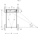
- the Ackermann-Jantoud type of FIG. 1 is a 4-bar link type, that is, four bars including a pair of knuckle arms 10, a tie rod 11, and a main rod 12 are connected by a link to operate.
- the knuckle arms are generated set to an angle in which virtual lines A and B connecting the pair of knuckle arms meet at the center of a rear axle.
- the front wheels 20 are rotated and rear wheels 30 follow.
- the right wheel illustrated in FIG. 1 turns more than the left wheel. Only then, the vehicle may turn with respect to a point O.
- FIG. 1 has been widely used due to its merits of being easy to implement as a simple structure of a 4-bar link type as described above, and steering the linear motion of the tie rod 11 with only a rotational motion in the form of a 4-bar link type.
- FIG. 1 Although the Ackermann-Jantoud type of FIG. 1 has widely been used because normal vehicles drive a relatively curved road, and slipping may be compensated for by a complement, such as suspension and the like, and person's judgement and the like, the Ackermann-Jantoud type of FIG. 1 has been known to be theoretically unable to remove the slipping.
- a Davis type expressed in a schematic drawing of FIG. 2 is the second type.
- This type has a structure to theoretically exclude slipping under all steering conditions, compared with the Ackermann-Jantoud type of FIG. 1 .
- the knuckle arm inclination angle set or setting with respect to a vehicle width W or a vehicle length L are most important. Only then, vehicles, in particular, autonomous driving vehicles that are driven without a driver, may reduce a path deviation error during autonomous steering and driving.
- an autonomous driving vehicle in which a knuckle arm inclination angle set operation with respect to a vehicle width or a vehicle length may be accurately, easily, and quickly performed, compared with the related art, so that not only mass-production of vehicles may be secured, but also a path deviation error during autonomous steering and driving may be reduced.
- a knuckle arm inclination angle set operation with respect to a vehicle width or a vehicle length may be accurately, easily, and quickly performed, compared with the related art, not only mass production of vehicles may be achieved, but also a path deviation error during autonomous steering and driving may be reduced.
- an autonomous driving vehicle includes a front wheel support connected to a front wheel as one body and supporting the front wheel, and a knuckle arm angle adjustment assembly having one side to which a knuckle arm is connected, the knuckle arm moving with the front wheel during steering the front wheel, and knuckle arm angle adjustment assembly being coupled to one side of the front wheel support to be capable of angle adjustment for setting an inclination angle of the knuckle arm.
- the knuckle arm angle adjustment assembly may include a sawtoothed knuckle arm angle adjustment assembly that is capable of angle adjustment by a preset angle with respect to the front wheel support through a sawtooth type method.
- the sawtoothed knuckle arm angle adjustment assembly may include an assembly body including an arm connection portion to which the knuckle arm is connected, a rotation shaft coupled to the assembly body to have both end portions of the rotation shaft exposed, and forming a rotation axis of the assembly body, an angle adjustment module connected to the rotation shaft forming one body, and having a first serration formed on one side of the angle adjustment module, and a module restriction portion restricting the angle adjustment module to one side of the front wheel support.
- the module restriction portion may include a module restriction main block having a second serration that is engaged with the first serration of the angle adjustment module, and a main fastening member fastening the module restriction main block to the front wheel support.
- the module restriction portion may further include a module restriction sub-block supporting the module restriction main block at a side of the module restriction main block, a block fastening member fastening the module restriction sub-block and the module restriction main block, and a sub-fastening member fastening the module restriction sub-block to the front wheel support.
- the front wheel support may include a support inner body disposed inside the front wheel, a lower shaft coupling portion connected to a lower portion of one side of the support inner body, and to which a lower end portion of the rotation shaft is coupled, an upper shaft coupling portion connected to an upper portion of the one side of the support inner body, and to which an upper end portion of the rotation shaft is coupled, a support outer body supporting the front wheel at a side opposite to the support inner body with the front wheel therebetween, and a plurality of body fastening members fastening the support outer body and the support inner body.
- First and second through-holes through which the main fastening member and the sub-fastening member pass, may be formed in the upper shaft coupling portion, and first and second fastening holes, through which the main fastening member and the sub-fastening member having passed through the first and second through-hole are fastened, may be formed in the module restriction main block and the module restriction sub-block, the first fastening hole being provided as a slot.
- a step portion may be formed in a lower end portion of the upper shaft coupling portion that is contacted by the module restriction main block and the module restriction sub-block.
- the autonomous driving vehicle may further include a vertical driving suspension connected to the assembly body through a rotation shaft of the knuckle arm angle adjustment assembly, and providing a shock-absorption force to a body of a vehicle by performing only a linear motion in a vertical direction to remove a change in a vehicle width.
- the vertical driving suspension may be independently mounted on both of the front wheel and a rear wheel disposed at a side opposite to the front wheel.
- the vertical driving suspension may include a suspension body, a spring coupled to the suspension body and performing shock-absorption in the vertical direction, a pair of coupling arms extending from the suspension body and coupled to both end portions of the assembly body, a lower head connected to a lower portion of the suspension body apart therefrom and coupled to a body frame, and an upper head connected to an upper portion of the suspension body apart therefrom and restricted to a front frame cover coupled to the body frame.
- the autonomous driving vehicle may further include a steering motor generating a driving force to steer the front wheel, a pinion connected to the steering motor and rotated by the steering motor, and a rack gear-engaged with the pinion, and transmitting a rotational motion of the pinion as a linear motion.
- the autonomous driving vehicle may further include a pair of knuckle arm support units each supporting the knuckle arm in an area of the front wheel, and a motion transmitting member coupled to the rack such that both end portions of the motion transmitting member are rotatably connected to the pair of knuckle arm support units, and transmitting a linear motion of the rack as a turning motion of the knuckle arm.
- the knuckle arm support unit may include an arm penetration support portion through which the knuckle arm passes and is supported thereon, a unit supporter supporting the arm penetration support portion outside the arm penetration support portion, and a rotating head portion rotatably connected to the unit supporter and disposed and fixed to a penetration portion formed in an end portion of the motion transmitting member.
- the pinion may include a pinion body having a disc shape, and a plurality of power transmission pins connected to the pinion body at equal intervals in a circumferential direction of the pinion body, and providing rotational power mutually corresponding to shapes of teeth formed on the rack.
- the autonomous driving vehicle may further include a pair of rear wheel driving portions respectively connected to a pair of rear wheels disposed at a side opposite to the front wheel, and providing a driving force to the pair of rear wheels, a common driving force providing portion commonly providing a driving force to drive the pair of rear wheel driving portions, and a rear wheel motion transmitting portion connected between the common driving force providing portion and each of the pair of rear wheel driving portions, and transmitting a motion of the common driving force providing portion to the pair of rear wheel driving portions.
- the common driving force providing portion may be provided as a modular composite device of an engine for generating a driving force, a reducer for reducing a speed of the engine, and a differential gear.
- the rear wheel motion transmitting portion may include a Schmidt coupling.
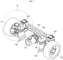
- FIG. 3 is a perspective view of an autonomous driving vehicle according to an embodiment of the inventive concept.
- FIG. 4 is a rear perspective view of FIG. 3 .
- FIG. 5 is a plan view of FIG. 3 .
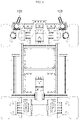
- FIG. 6 is a plan view in which, in FIG. 5 , to emphasize the knuckle arm, the other parts except a knuckle arm are indicated by dashed lines.
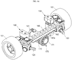
- FIG. 7 is an enlarged view of a region A of FIG. 3 .
- FIG. 8 illustrates the opposite side after removing parts of a body frame are removed in FIG. 7 .
- FIG. 9 illustrates a state of removing a linear guide in FIG. 8 .
- FIG. 10 illustrates the opposite side of FIG. 9 .
- FIG. 11 is a partially exploded view of FIG.
- FIG. 12 is an exploded view of a pinion and a rack in FIG. 11 .
- FIG. 13 is a partially exploded enlarged view of a region B of FIG. 9 .
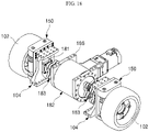
- FIG. 14 is a detailed exploded view of FIG. 13 .
- FIG. 15 is a detailed exploded view of FIG. 14 .
- FIG. 16 is a detailed exploded view of FIG. 15 .
- FIG. 17 is an enlarged view of a region C of FIG. 4 .
- FIG. 18 is a detailed view of a region of a rear wheel driving portion of FIG. 17 .
- FIG. 19 is an exploded view of FIG. 18 .
- an autonomous driving vehicle 100 as an inclination angle set operation of a knuckle arm 120 with respect to a vehicle width W or a vehicle length L may be accurately, easily, and quickly performed, compared with the related art, not only mass production of vehicles may be achieved, but also a path deviation error during autonomous steering and driving may be reduced.
- the inclination angle set operation of the knuckle arm 120 (hereinafter, referred to as the setting operation) in the existing vehicle is carried out by a fine screw adjustment method using a double nut that is not illustrated, and thus, a working time is inevitably slow.
- the inclination angle setting operation of the knuckle arm 120 may be conveniently performed by a serration method (see 134a and 141a of FIG. 16 ), and thus, the working time may be greatly reduced. Accordingly, mass productivity of the autonomous driving vehicle 100 is increased so that it is enough to secure competitiveness.
- a power transmission structure for steering, driving, or shock absorption of the autonomous driving vehicle 100 needs to be set to perform a linear motion without a link motion.
- the autonomous driving vehicle 100 includes a body frame 104, and a front wheel 101 and a rear wheel 102, each being provided in a pair and rotatably coupled respectively to the front end and rear end of the body frame 104, and has a shape in which a structure, a unit, or an apparatus, such as a knuckle arm angle adjustment assembly 130, is connected to the front wheel 101 and the rear wheel 102 by means of the body frame 104.
- the body frame 104 is a structure that supports all components, units, or apparatuses, including the front wheel 101 and the rear wheel 102, forming the autonomous driving vehicle 100.
- the body frame 104 may include a metal frame that is light and exhibits excellent stiffness.
- body frame is illustrated as having a reference numeral 104 in the drawings, the body frame 104 may be one large integral mass structure, or a partially screw-assembled structure.
- the body frame 104 supports all components, units, or apparatuses, including the front wheel 101 and the rear wheel 102, forming the autonomous driving vehicle 100
- the body frame 104 needs not necessarily have the same shape as the shape in the drawings.
- the right scope of the present inventive concept is not limited to the shape in the drawings.
- the front wheel 101 is provided with a front wheel support 110 that is connected to front wheel 101 as one body and supports the front wheel 101.
- the front wheel support 110 may enable the knuckle arm angle adjustment assembly 130, a module restriction portion 140, a vertical driving suspension 150, and the like to be stably mounted thereon.
- the front wheel support 110 may include a support inner body 111 disposed inside the front wheel 101, a support outer body 114 supporting the front wheel 101 at a side opposite to the support inner body 111 with the front wheel 101 therebetween, and a plurality of body fastening members 115 for fastening the support outer body 114 and the support inner body 111.
- the front wheel support 110 may be easily installed on the front wheel 101. Disassembly may be performed in the opposite method.
- a lower shaft coupling portion 112 and a upper shaft coupling portion 113 are coupled to the support inner body 111.
- the lower shaft coupling portion 112 and the upper shaft coupling portion 113 form an integral structure with the support inner body 111.
- the lower shaft coupling portion 112 is connected to a lower portion of one side of the support inner body 111, and forms a place for coupling a lower end portion of a rotation shaft 133 forming the knuckle arm angle adjustment assembly 130.
- the upper shaft coupling portion 113 is connected to an upper portion of the one side of the support inner body 111, and forms a place for coupling an upper end portion of the rotation shaft 133.
- the front wheel support 110 is assembled to the front wheel 101, and the knuckle arm angle adjustment assembly 130 is connected through the lower shaft coupling portion 112 and the upper shaft coupling portion 113 of the front wheel support 110, the front wheel support 110, the knuckle arm angle adjustment assembly 130, and the front wheel 101 may have a structure connected in one mass.
- a knuckle arm 120 moving with the front wheel 101 during steering the front wheel 101 is connected to one side of the knuckle arm angle adjustment assembly 130, and the knuckle arm 120 is coupled to one side of the front wheel support 110 such that angle adjustment is possible for the inclination angle setting of knuckle arm 120.
- the knuckle arm angle adjustment assembly 130 may be a sawtoothed knuckle arm angle adjustment assembly that is angle-adjustable by a preset angle with respect to the front wheel support 110 through a sawtooth method, that is, the serration method (see 134a and 141a of FIG. 16 ).
- the inclination angle setting operation of the knuckle arm 120 may be easily and quickly performed and also the angle adjustment may be further accurately performed.
- the knuckle arm angle adjustment assembly 130 of a sawtooth type may include an assembly body 131, the rotation shaft 133 forming the rotation axis of the assembly body 131, an angle adjustment module 134 connected to the rotation shaft 133, forming one body with the rotation shaft 133, and having a first serration 134a at one side thereof, and the module restriction portion 140 that restricts the angle adjustment module 134 to the one side of the front wheel support 110.
- the assembly body 131 forms the frame of the knuckle arm angle adjustment assembly 130 of a sawtooth type. Structures such as the rotation shaft 133, the angle adjustment module 134, and the like are mounted, by locations, on the assembly body 131.
- An arm connection portion 132 to which the knuckle arm 120 is connected is formed on the assembly body 131.
- the knuckle arm 120 having a non-circular cross-sectional structure has one end portion connected to the arm connection portion 132 and the other end portion connected to an arm penetration support portion 165a of a knuckle arm support unit 165 to be exposed. Accordingly, when the knuckle arm support unit 165 is operated, the knuckle arm 120 rotates and then the front wheel 101 may be steered.
- rotation shaft 133 forms the rotation axis of the assembly body 131, both end portions of the rotation shaft 133 are coupled to the assembly body 131 to be exposed to the outside.
- the vertical driving suspension 150 and the front wheel support 110 may be assembled to both end portions of the rotation shaft 133. Accordingly, these components may be connected to each other as one body with the front wheel 101.
- the angle adjustment module 134 has a structure to be connected to the rotation shaft 133 and forming one body with the rotation shaft 133.
- the first serration 134a is formed at one side of the angle adjustment module 134.
- the inclination angle setting operation of the knuckle arm 120 is briefly described with reference to FIG. 16 .
- the module restriction main block 141 is fastened to the upper shaft coupling portion 113 of the front wheel support 110.
- the module restriction main block 141 is released and the angle adjustment module 134 that forms one body with the rotation shaft 133 is rotated by a desired angle
- the module restriction main block 141 is fixed to the upper shaft coupling portion 113 of the front wheel support 110 such that the first and second serrations 134a and 141a are restricted with each other, thereby very simply performing the inclination angle setting operation of the knuckle arm 120.
- the inclination angle setting operation of the knuckle arm 120 may be quickly and precisely performed.
- the module restriction portion 140 serves to restrict the angle adjustment module 134 to one side of the front wheel support 110.
- the module restriction portion 140 may include the module restriction main block 141 having the second serration 141a that is engaged with the first serration 134a of the angle adjustment module 134, and a plurality of main fastening members 142 for fastening the module restriction main block 141 to the front wheel support 110.
- a module restriction sub-block 143 is provided at one side of the module restriction main block 141.
- the module restriction sub-block 143 serves to support the module restriction main block 141 at a side of the module restriction main block 141.
- the module restriction sub-block 143 and the module restriction main block 141 are fastened through a block fastening member 144 to form one body.
- the angle adjustment module 134 may be supported by only the module restriction main block 141, without the module restriction sub-block 143, by further employing the module restriction sub-block 143, the angle adjustment module 134 may be supported with a more stable and strong force.
- the module restriction sub-block 143 may be fastened by a plurality of sub-fastening members 145 to the front wheel support 110.
- First and second through-holes 113a and 113b through which the main fastening members 142 and the sub-fastening members 145 pass are formed in the upper shaft coupling portion 113 so that the module restriction main block 141 and the module restriction sub-block 143 are coupled to the upper shaft coupling portion 113 of the body frame 104.
- the first and second fastening holes 141b and 143a to which the main fastening members 142 and the sub-fastening members 145 having passed through the first and second through-holes 113a and 113b are fastened, are respectively formed in the module restriction main block 141 and the module restriction sub-block 143, and unlike the second fastening hole 143a, the first fastening hole 141b is provided as a slot. Accordingly, it is effective to adjust assembly tolerance between parts.
- a step portion 113c is formed in a lower end portion of the upper shaft coupling portion 113 that is contacted by the module restriction main block 141 and the module restriction sub-block 143. As in an enlarged view of FIG. 14 , as the module restriction sub-block 143 is disposed on the step portion 113c, the module restriction sub-block 143 is not pushed and stably supports the module restriction main block 141.
- the power transmission structure for steering, driving, or shock absorption of the autonomous driving vehicle 100 is employed to perform a linear motion without a link motion, which is described below.
- a steering motor 161 for generating a driving force for steering the front wheel 101 is provided in the autonomous driving vehicle 100 according to the present embodiment.
- the autonomous driving vehicle 100 employs a pinion 170 and a rack 162, and a motion transmitting member 163 is connected to the rack 162 and the knuckle arm support unit 165 for supporting the knuckle arm 120 is connected to the motion transmitting member 163.
- the steering motor 161 generates a driving force to steer the front wheel 101.
- the pinion 170 is connected to the steering motor 161. In the present embodiment, as the steering motor 161 is fixedly mounted on the body frame 104, the pinion 170 rotates in place.
- the pinion 170 has a structure to be connected to the steering motor 161 and rotated by the steering motor 161.
- the rack 162 is gear-engaged with the pinion 170, and serves to transmit the rotational motion of the pinion 170 as a linear motion.
- the pinion 170 having a structure described below is employed.
- the pinion 170 employed in the present embodiment includes a pinion body 171 having a disc shape, and a plurality of power transmission pins 172 connected to the pinion body 171 at equal intervals in the circumferential direction of the pinion body 171, and providing rotational power mutually corresponding to the shape of teeth 162a formed on the rack 162.
- the power transmission pins 172 have an arrangement structure of a circular shape in the pinion body 171, and rotate mutually corresponding to the shapes of teeth 162a formed on the rack 162.
- the power transmission pins 172 of the pinion 170 are tooth-engaged with the teeth 162a formed on the rack 162, and thus, the rack 162 performs a linear motion.
- the motion transmitting member 163 connected to the rack 162 as one body is guided by linear guides 168 restricted to the body frame 104 through a front frame cover 105, to perform a linear motion horizontally, that is, to the left and right.
- the knuckle arm 120 is turned to the left and right through the knuckle arm support unit 165 connected to each of both end portions of the motion transmitting member 163, so as to move the front wheel 101, that is, to be steered.
- the linear guides 168 are fixed to the front frame cover 105 with a motor support 169 for fixing the steering motor 161, and the front frame cover 105 has a shape to be connected to the body frame 104.
- the motion transmitting member 163 is connected to the linear guides 168 and guided thereby so that the horizontal linear motion of the motion transmitting member 163 may be stably performed.
- the knuckle arm support unit 165 for supporting the knuckle arm 120 is provided in the area of the front wheel 101.
- the knuckle arm support unit 165 may include the arm penetration support portion 165a through which the knuckle arm 120 passes and is supported thereon, a unit supporter 165b supporting the arm penetration support portion 165a outside the arm penetration support portion 165a, and a rotating head portion 165c rotatably connected to the unit supporter 165b and disposed in and fixed to a penetration portion 163a formed in an end portion of the motion transmitting member 163.
- the knuckle arm 120 and the arm penetration support portion 165a have a non-circular sectional coupling structure, the knuckle arm 120 does not idle in the arm penetration support portion 165a.
- the motion transmitting member 163 is connected to the rack 162 described above, forming one body.
- the motion transmitting member 163 is coupled to the rack 162 with both end portions thereof rotatably connected to the pair of knuckle arm support units 165, and serves to transmit the linear motion of the rack 162 as a turning motion of the knuckle arm 120.
- the present embodiment adopts a linear turning and rolling motion method in which the linear motion of the motion transmitting member 163 turns the knuckle arm 120 to steer the front wheel 101, no link structure is needed unlike the related art, and thus, a change in the vehicle width W or the vehicle length L may be removed, and furthermore, may contribute to reduction of occurrence of sliding abrasion.
- the vertical driving suspension 150 is employed to prevent an effect on the occurrence of a change in the vehicle width W or the vehicle length L.
- the vertical driving suspension 150 for providing a shock-absorption function to a vehicle is connected to the assembly body 131 through the rotation shaft 133 of the knuckle arm angle adjustment assembly 130, and provides a shock-absorption force to the body of a vehicle while performing a linear motion only in a vertical direction to remove the occurrence of a change in the vehicle width W or the vehicle length L, in particular a change in the vehicle width W.
- the vertical driving suspension 150 may be independently mounted on all of the pair of front wheels 101 and the pair of rear wheels 102.
- the vertical driving suspension 150 may include a suspension body 151, springs 152 coupled to the suspension body 151 and perform shock-absorption in the vertical direction, a pair of coupling arms 153 extending from the suspension body 151 and coupled to both end portions of the assembly body 131, a lower head 154 connected to a lower portion of the suspension body 151 apart therefrom and coupled to the body frame 104, and an upper head 155 connected to an upper portion of the suspension body 151 apart therefrom and restricted to the front frame cover 105 that is coupled to the body frame 104.
- the autonomous driving vehicle 100 is equipped with, as means for driving a vehicle, a pair of rear wheel driving portions 181, a common driving force providing portion 182, and a rear wheel motion transmitting portion 183.
- Each of the rear wheel driving portions 181 is connected to the rear wheel 102, and provides a driving force to the rear wheel 102.
- the common driving force providing portion 182 provides a driving force for driving the rear wheel driving portions 181 for common use.
- the common driving force providing portion 182 is connected to a motion transmitting portion 183 by being supported by a supporter 186.
- the supporter 186 is connected to the body frame 104 through a rear frame cover 106. As a result, the common driving force providing portion 182 may be stably position-fixed to the body frame 104.
- the common driving force providing portion 182 is provided as a modular composite device of an engine for generating a driving force, a reducer for reducing the speed of the engine, and a differential gear.
- modularized components may facilitate assembly and maintenance/repair, in particular miniaturization.
- the rear wheel motion transmitting portion 183 is connected between the common driving force providing portion 182 and each of the rear wheel driving portions 181, and transmits the motion of the common driving force providing portion 182 to each of the rear wheel driving portions 181.
- the rear wheel motion transmitting portion 183 adopts a Schmidt coupling.
- the Schmidt coupling efficiently guarantees continuity in power transmission, and accurately transmits a motion and torque even when a large magnitude of eccentricity occurs.
- the Schmidt coupling has a merit in that, even when a large magnitude of eccentricity is absorbed, left-and-right distances from the relative axis do not change.
- the restrictions of the module restriction main block 141 and the module restriction sub-block 143 are removed.
- the screw-engagement between the first and second serrations 134a and 141a is removed, and in this state, the rotation shaft 133 of the assembly body 131 is rotated by a desired angle through the angle adjustment module 134.
- the inclination angle setting operation of the knuckle arm 120 may be performed by rotating the rotation shaft 133 by one pitch.
- the module restriction sub-block 143 is disposed at the side of the module restriction main block 141 and the module restriction main block 141 and the module restriction sub-block 143 are fixed by using the body fastening members 115.
- the inclination angle setting operation of the knuckle arm 120 with respect to the vehicle width W or the vehicle length L may be quickly and precisely performed.
- the inclination angle set operation of the knuckle arm 120 with respect to the vehicle width W or the vehicle length L may be accurately, easily, and quickly performed, compared with the related art, not only mass production of vehicles may be achieved, but also a path deviation error during autonomous steering and driving may be reduced.
- the present inventive concept may be used for the field of autonomous driving vehicles.
Landscapes
- Engineering & Computer Science (AREA)
- Mechanical Engineering (AREA)
- Transportation (AREA)
- Chemical & Material Sciences (AREA)
- Combustion & Propulsion (AREA)
- Automation & Control Theory (AREA)
- Steering-Linkage Mechanisms And Four-Wheel Steering (AREA)
- Vehicle Body Suspensions (AREA)
Abstract
Description
- The present inventive concept relates to an autonomous driving vehicle, and more particularly, to an autonomous driving vehicle in which a knuckle arm inclination angle set operation with respect to a vehicle width or a vehicle length may be accurately, easily, and quickly performed, compared with the related art, so that not only mass-production of vehicles may be secured, but also a path deviation error during autonomous steering and driving may be reduced.
- A steering system (apparatus) is mounted on a vehicle. A steering system is a kind of system that enables a vehicle to turn as a wheel (front wheel) is turned when a handle called a steering wheel (wheel) is turned.
- The steering system includes two types of methods as shown in
FIGS. 1 and2 . - An Ackermann-Jantoud type is the first type and schematically illustrated in
FIG. 1 . - The Ackermann-Jantoud type of
FIG. 1 is a 4-bar link type, that is, four bars including a pair ofknuckle arms 10, atie rod 11, and amain rod 12 are connected by a link to operate. - In this state, the knuckle arms are generated set to an angle in which virtual lines A and B connecting the pair of knuckle arms meet at the center of a rear axle.
- When a handle that is not illustrated is rotated, a steering shaft connected to the handle is rotated, a pinion gear connected to the steering shaft is rotated, and the
tie rod 11 is moved through a rack gear connected to the pinion gear, so that the knuckle arms are driven. - Then, starting from a wheel pivot (not shown), the
front wheels 20 are rotated andrear wheels 30 follow. In this state, among thefront wheels 20, the right wheel illustrated inFIG. 1 turns more than the left wheel. Only then, the vehicle may turn with respect to a point O. - Meanwhile, the Ackermann-Jantoud type of
FIG. 1 has been widely used due to its merits of being easy to implement as a simple structure of a 4-bar link type as described above, and steering the linear motion of thetie rod 11 with only a rotational motion in the form of a 4-bar link type. - However, when steering is made from a solid line to a dashed line in
FIG. 1 , unless inclined at an angle, the rotation center is deviated from a rear axle extension line and slipping occurs. However, when thetie rod 11 is restricted to perform a linear motion only, a desired steering repulsive force may not be obtained, and thus, during steering, the rotation center necessarily deviates from the rear axle extension line. Accordingly, for the Ackermann-Jantoud type ofFIG. 1 , a certain level of slipping is bound to occur. - Although the Ackermann-Jantoud type of
FIG. 1 has widely been used because normal vehicles drive a relatively curved road, and slipping may be compensated for by a complement, such as suspension and the like, and person's judgement and the like, the Ackermann-Jantoud type ofFIG. 1 has been known to be theoretically unable to remove the slipping. - A Davis type expressed in a schematic drawing of
FIG. 2 is the second type. - This type has a structure to theoretically exclude slipping under all steering conditions, compared with the Ackermann-Jantoud type of
FIG. 1 . - However, as many sliding
portions 50 are mounted and there are many sliding linear motions, and thus, friction and abrasion increase and precision is degraded so that this type is not known to be used well. - Meanwhile, when any of the above-described types is adopted, for smooth steering and driving, the knuckle arm inclination angle set or setting with respect to a vehicle width W or a vehicle length L are most important. Only then, vehicles, in particular, autonomous driving vehicles that are driven without a driver, may reduce a path deviation error during autonomous steering and driving.
- Conventionally, however, a fine screw adjustment method using a double nut has been adopted to set an inclination angle of the knuckle arms with respect to the vehicle width W or the vehicle length L, but since the knuckle arm inclination angle set operation is not easy and takes a long time. When this classical method is applied, as it is, to autonomous driving vehicles, each of vehicles having different vehicle widths W or different vehicle lengths L requires resetting so that mass production may be degraded. Considering the above, there is a need to develop technology about a new concept of an autonomous driving vehicle that is previously unknown.
- Provided is an autonomous driving vehicle in which a knuckle arm inclination angle set operation with respect to a vehicle width or a vehicle length may be accurately, easily, and quickly performed, compared with the related art, so that not only mass-production of vehicles may be secured, but also a path deviation error during autonomous steering and driving may be reduced.
- According to the present inventive concept, as a knuckle arm inclination angle set operation with respect to a vehicle width or a vehicle length may be accurately, easily, and quickly performed, compared with the related art, not only mass production of vehicles may be achieved, but also a path deviation error during autonomous steering and driving may be reduced.
-
-
FIG. 1 is a schematic structural diagram of a steering system of an Ackermann-Jantoud type. -
FIG. 2 is a schematic structural diagram of a steering system of a Davis type. -
FIG. 3 is a perspective view of an autonomous driving vehicle according to an embodiment of the inventive concept. -
FIG. 4 is a rear perspective view ofFIG. 3 . -
FIG. 5 is a plan view ofFIG. 3 . -
FIG. 6 is a plan view in which, inFIG. 5 , to emphasize the knuckle arm, the other parts except a knuckle arm are indicated by dashed lines. -
FIG. 7 is an enlarged view of a region A ofFIG. 3 . -
FIG. 8 illustrates the opposite side after removing parts of a body frame are removed inFIG. 7 . -
FIG. 9 illustrates a state of removing a linear guide inFIG. 8 . -
FIG. 10 illustrates the opposite side ofFIG. 9 . -
FIG. 11 is a partially exploded view ofFIG. 10 . -
FIG. 12 is an exploded view of a pinion and a rack inFIG. 11 . -
FIG. 13 is a partially exploded enlarged view of a region B ofFIG. 9 . -
FIG. 14 is a detailed exploded view ofFIG. 13 . -
FIG. 15 is a detailed exploded view ofFIG. 14 . -
FIG. 16 is a detailed exploded view ofFIG. 15 . -
FIG. 17 is an enlarged view of a region C ofFIG. 4 . -
FIG. 18 is a detailed view of a region of a rear wheel driving portion ofFIG. 17 . -
FIG. 19 is an exploded view ofFIG. 18 . - According to an aspect of the present inventive concept, an autonomous driving vehicle includes a front wheel support connected to a front wheel as one body and supporting the front wheel, and a knuckle arm angle adjustment assembly having one side to which a knuckle arm is connected, the knuckle arm moving with the front wheel during steering the front wheel, and knuckle arm angle adjustment assembly being coupled to one side of the front wheel support to be capable of angle adjustment for setting an inclination angle of the knuckle arm.
- The knuckle arm angle adjustment assembly may include a sawtoothed knuckle arm angle adjustment assembly that is capable of angle adjustment by a preset angle with respect to the front wheel support through a sawtooth type method.
- The sawtoothed knuckle arm angle adjustment assembly may include an assembly body including an arm connection portion to which the knuckle arm is connected, a rotation shaft coupled to the assembly body to have both end portions of the rotation shaft exposed, and forming a rotation axis of the assembly body, an angle adjustment module connected to the rotation shaft forming one body, and having a first serration formed on one side of the angle adjustment module, and a module restriction portion restricting the angle adjustment module to one side of the front wheel support.
- The module restriction portion may include a module restriction main block having a second serration that is engaged with the first serration of the angle adjustment module, and a main fastening member fastening the module restriction main block to the front wheel support.
- The module restriction portion may further include a module restriction sub-block supporting the module restriction main block at a side of the module restriction main block, a block fastening member fastening the module restriction sub-block and the module restriction main block, and a sub-fastening member fastening the module restriction sub-block to the front wheel support.
- The front wheel support may include a support inner body disposed inside the front wheel, a lower shaft coupling portion connected to a lower portion of one side of the support inner body, and to which a lower end portion of the rotation shaft is coupled, an upper shaft coupling portion connected to an upper portion of the one side of the support inner body, and to which an upper end portion of the rotation shaft is coupled, a support outer body supporting the front wheel at a side opposite to the support inner body with the front wheel therebetween, and a plurality of body fastening members fastening the support outer body and the support inner body.
- First and second through-holes, through which the main fastening member and the sub-fastening member pass, may be formed in the upper shaft coupling portion, and first and second fastening holes, through which the main fastening member and the sub-fastening member having passed through the first and second through-hole are fastened, may be formed in the module restriction main block and the module restriction sub-block, the first fastening hole being provided as a slot.
- A step portion may be formed in a lower end portion of the upper shaft coupling portion that is contacted by the module restriction main block and the module restriction sub-block.
- The autonomous driving vehicle may further include a vertical driving suspension connected to the assembly body through a rotation shaft of the knuckle arm angle adjustment assembly, and providing a shock-absorption force to a body of a vehicle by performing only a linear motion in a vertical direction to remove a change in a vehicle width.
- The vertical driving suspension may be independently mounted on both of the front wheel and a rear wheel disposed at a side opposite to the front wheel.
- The vertical driving suspension may include a suspension body, a spring coupled to the suspension body and performing shock-absorption in the vertical direction, a pair of coupling arms extending from the suspension body and coupled to both end portions of the assembly body, a lower head connected to a lower portion of the suspension body apart therefrom and coupled to a body frame, and an upper head connected to an upper portion of the suspension body apart therefrom and restricted to a front frame cover coupled to the body frame.
- The autonomous driving vehicle may further include a steering motor generating a driving force to steer the front wheel, a pinion connected to the steering motor and rotated by the steering motor, and a rack gear-engaged with the pinion, and transmitting a rotational motion of the pinion as a linear motion.
- The autonomous driving vehicle may further include a pair of knuckle arm support units each supporting the knuckle arm in an area of the front wheel, and a motion transmitting member coupled to the rack such that both end portions of the motion transmitting member are rotatably connected to the pair of knuckle arm support units, and transmitting a linear motion of the rack as a turning motion of the knuckle arm.
- The knuckle arm support unit may include an arm penetration support portion through which the knuckle arm passes and is supported thereon, a unit supporter supporting the arm penetration support portion outside the arm penetration support portion, and a rotating head portion rotatably connected to the unit supporter and disposed and fixed to a penetration portion formed in an end portion of the motion transmitting member.
- The pinion may include a pinion body having a disc shape, and a plurality of power transmission pins connected to the pinion body at equal intervals in a circumferential direction of the pinion body, and providing rotational power mutually corresponding to shapes of teeth formed on the rack.
- The autonomous driving vehicle may further include a pair of rear wheel driving portions respectively connected to a pair of rear wheels disposed at a side opposite to the front wheel, and providing a driving force to the pair of rear wheels, a common driving force providing portion commonly providing a driving force to drive the pair of rear wheel driving portions, and a rear wheel motion transmitting portion connected between the common driving force providing portion and each of the pair of rear wheel driving portions, and transmitting a motion of the common driving force providing portion to the pair of rear wheel driving portions.
- The common driving force providing portion may be provided as a modular composite device of an engine for generating a driving force, a reducer for reducing a speed of the engine, and a differential gear.
- The rear wheel motion transmitting portion may include a Schmidt coupling.
- In order to fully understand the operational advantages of the present inventive concept and the objectives achieved by the implementation of the present inventive concept, the accompanying drawings illustrating preferred embodiments of the present inventive concept and the contents described in the accompanying drawings are referred to.
- Hereinafter, the inventive concept will be described in detail by explaining preferred embodiments of the inventive concept with reference to the attached drawings. Like reference numerals in the drawings denote like elements.
- The attached drawings for illustrating preferred embodiments of the disclosure are referred to in order to gain a sufficient understanding of the disclosure, the merits thereof, and the objectives accomplished by the implementation of the disclosure.
- Hereinafter, the disclosure will be described in detail by explaining preferred embodiments of the disclosure with reference to the attached drawings. Like reference numerals in the drawings denote like elements.
-
FIG. 3 is a perspective view of an autonomous driving vehicle according to an embodiment of the inventive concept.FIG. 4 is a rear perspective view ofFIG. 3 .FIG. 5 is a plan view ofFIG. 3 .FIG. 6 is a plan view in which, inFIG. 5 , to emphasize the knuckle arm, the other parts except a knuckle arm are indicated by dashed lines.FIG. 7 is an enlarged view of a region A ofFIG. 3 .FIG. 8 illustrates the opposite side after removing parts of a body frame are removed inFIG. 7 .FIG. 9 illustrates a state of removing a linear guide inFIG. 8 .FIG. 10 illustrates the opposite side ofFIG. 9 .FIG. 11 is a partially exploded view ofFIG. 10 .FIG. 12 is an exploded view of a pinion and a rack inFIG. 11 .FIG. 13 is a partially exploded enlarged view of a region B ofFIG. 9 .FIG. 14 is a detailed exploded view ofFIG. 13 .FIG. 15 is a detailed exploded view ofFIG. 14 .FIG. 16 is a detailed exploded view ofFIG. 15 .FIG. 17 is an enlarged view of a region C ofFIG. 4 .FIG. 18 is a detailed view of a region of a rear wheel driving portion ofFIG. 17 .FIG. 19 is an exploded view ofFIG. 18 . - Referring to these drawings, in an
autonomous driving vehicle 100 according to the present embodiment, as an inclination angle set operation of aknuckle arm 120 with respect to a vehicle width W or a vehicle length L may be accurately, easily, and quickly performed, compared with the related art, not only mass production of vehicles may be achieved, but also a path deviation error during autonomous steering and driving may be reduced. - In other words, as mentioned above, the inclination angle set operation of the knuckle arm 120 (hereinafter, referred to as the setting operation) in the existing vehicle is carried out by a fine screw adjustment method using a double nut that is not illustrated, and thus, a working time is inevitably slow.
- As such, when a time for the inclination angle setting operation of the
knuckle arm 120 increases, the mass production of theautonomous driving vehicle 100 may be difficult to achieve, and thus, actual production becomes impossible. - However, in the case of the present embodiment, as described below, the inclination angle setting operation of the
knuckle arm 120 may be conveniently performed by a serration method (see 134a and 141a ofFIG. 16 ), and thus, the working time may be greatly reduced. Accordingly, mass productivity of theautonomous driving vehicle 100 is increased so that it is enough to secure competitiveness. - In order to provide such an effect, there must be no change in the length of the vehicle width W or the vehicle length L, and to this end, as in the present embodiment, a power transmission structure for steering, driving, or shock absorption of the
autonomous driving vehicle 100 needs to be set to perform a linear motion without a link motion. With the above structure, the actual structure and operation of the inclination angle setting operation of theknuckle arm 120 are described below in detail. - Meanwhile, the
autonomous driving vehicle 100 according to the present embodiment that can provide the above effect includes abody frame 104, and afront wheel 101 and arear wheel 102, each being provided in a pair and rotatably coupled respectively to the front end and rear end of thebody frame 104, and has a shape in which a structure, a unit, or an apparatus, such as a knuckle armangle adjustment assembly 130, is connected to thefront wheel 101 and therear wheel 102 by means of thebody frame 104. - First, the
body frame 104 is a structure that supports all components, units, or apparatuses, including thefront wheel 101 and therear wheel 102, forming theautonomous driving vehicle 100. Thebody frame 104 may include a metal frame that is light and exhibits excellent stiffness. - While a body frame is illustrated as having a
reference numeral 104 in the drawings, thebody frame 104 may be one large integral mass structure, or a partially screw-assembled structure. - In particular, as it is sufficient that the
body frame 104 supports all components, units, or apparatuses, including thefront wheel 101 and therear wheel 102, forming theautonomous driving vehicle 100, thebody frame 104 needs not necessarily have the same shape as the shape in the drawings. In other words, the right scope of the present inventive concept is not limited to the shape in the drawings. - The
front wheel 101 is provided with afront wheel support 110 that is connected tofront wheel 101 as one body and supports thefront wheel 101. - As illustrated in detail in
FIGS. 14 to 16 , while rotatably supporting thefront wheel 101, thefront wheel support 110 may enable the knuckle armangle adjustment assembly 130, amodule restriction portion 140, avertical driving suspension 150, and the like to be stably mounted thereon. - The
front wheel support 110 may include a supportinner body 111 disposed inside thefront wheel 101, a supportouter body 114 supporting thefront wheel 101 at a side opposite to the supportinner body 111 with thefront wheel 101 therebetween, and a plurality ofbody fastening members 115 for fastening the supportouter body 114 and the supportinner body 111. - Accordingly, as the support
inner body 111 is disposed inside thefront wheel 101 and the supportouter body 114 is disposed outside thefront wheel 101, and the supportouter body 114 and the supportinner body 111 are connected as one body by using thebody fastening members 115 for fastening, thefront wheel support 110 may be easily installed on thefront wheel 101. Disassembly may be performed in the opposite method. - A lower
shaft coupling portion 112 and a uppershaft coupling portion 113 are coupled to the supportinner body 111. The lowershaft coupling portion 112 and the uppershaft coupling portion 113 form an integral structure with the supportinner body 111. - The lower
shaft coupling portion 112 is connected to a lower portion of one side of the supportinner body 111, and forms a place for coupling a lower end portion of arotation shaft 133 forming the knuckle armangle adjustment assembly 130. - The upper
shaft coupling portion 113 is connected to an upper portion of the one side of the supportinner body 111, and forms a place for coupling an upper end portion of therotation shaft 133. - As such, as the
front wheel support 110 is assembled to thefront wheel 101, and the knuckle armangle adjustment assembly 130 is connected through the lowershaft coupling portion 112 and the uppershaft coupling portion 113 of thefront wheel support 110, thefront wheel support 110, the knuckle armangle adjustment assembly 130, and thefront wheel 101 may have a structure connected in one mass. - Meanwhile, a
knuckle arm 120 moving with thefront wheel 101 during steering thefront wheel 101 is connected to one side of the knuckle armangle adjustment assembly 130, and theknuckle arm 120 is coupled to one side of thefront wheel support 110 such that angle adjustment is possible for the inclination angle setting ofknuckle arm 120. - In the present embodiment, the knuckle arm
angle adjustment assembly 130 may be a sawtoothed knuckle arm angle adjustment assembly that is angle-adjustable by a preset angle with respect to thefront wheel support 110 through a sawtooth method, that is, the serration method (see 134a and 141a ofFIG. 16 ). - As in the present embodiment, when the knuckle arm
angle adjustment assembly 130 of a sawtooth type is employed, compared with the existing fine screw adjustment method using a double nut, the inclination angle setting operation of theknuckle arm 120 may be easily and quickly performed and also the angle adjustment may be further accurately performed. - As mainly illustrated in detail in
FIGS. 15 and16 , the knuckle armangle adjustment assembly 130 of a sawtooth type may include anassembly body 131, therotation shaft 133 forming the rotation axis of theassembly body 131, anangle adjustment module 134 connected to therotation shaft 133, forming one body with therotation shaft 133, and having afirst serration 134a at one side thereof, and themodule restriction portion 140 that restricts theangle adjustment module 134 to the one side of thefront wheel support 110. - The
assembly body 131 forms the frame of the knuckle armangle adjustment assembly 130 of a sawtooth type. Structures such as therotation shaft 133, theangle adjustment module 134, and the like are mounted, by locations, on theassembly body 131. - An
arm connection portion 132 to which theknuckle arm 120 is connected is formed on theassembly body 131. Theknuckle arm 120 having a non-circular cross-sectional structure has one end portion connected to thearm connection portion 132 and the other end portion connected to an armpenetration support portion 165a of a knucklearm support unit 165 to be exposed. Accordingly, when the knucklearm support unit 165 is operated, theknuckle arm 120 rotates and then thefront wheel 101 may be steered. - While the
rotation shaft 133 forms the rotation axis of theassembly body 131, both end portions of therotation shaft 133 are coupled to theassembly body 131 to be exposed to the outside. - As both end portions of the
rotation shaft 133 are exposed to the outside of theassembly body 131 as in the present embodiment, thevertical driving suspension 150 and thefront wheel support 110 may be assembled to both end portions of therotation shaft 133. Accordingly, these components may be connected to each other as one body with thefront wheel 101. - The
angle adjustment module 134 has a structure to be connected to therotation shaft 133 and forming one body with therotation shaft 133. Thefirst serration 134a is formed at one side of theangle adjustment module 134. - The inclination angle setting operation of the
knuckle arm 120 is briefly described with reference toFIG. 16 . In the case of the present embodiment, while asecond serration 141a of a module restrictionmain block 141 forming themodule restriction portion 140 is engaged, in a screw type, with thefirst serration 134a of theangle adjustment module 134, the module restrictionmain block 141 is fastened to the uppershaft coupling portion 113 of thefront wheel support 110. Thus, after the module restrictionmain block 141 is released and theangle adjustment module 134 that forms one body with therotation shaft 133 is rotated by a desired angle, the module restrictionmain block 141 is fixed to the uppershaft coupling portion 113 of thefront wheel support 110 such that the first andsecond serrations knuckle arm 120. - In particular, as it is possible to perform the inclination angle setting operation of the
knuckle arm 120 by rotating, by one pitch, theangle adjustment module 134 through the first andsecond serrations knuckle arm 120 with respect to the vehicle width W or the vehicle length L may be quickly and precisely performed. - In the
module restriction portion 140 forming the knuckle armangle adjustment assembly 130 of a sawtooth type, themodule restriction portion 140 serves to restrict theangle adjustment module 134 to one side of thefront wheel support 110. - The
module restriction portion 140 may include the module restrictionmain block 141 having thesecond serration 141a that is engaged with thefirst serration 134a of theangle adjustment module 134, and a plurality ofmain fastening members 142 for fastening the module restrictionmain block 141 to thefront wheel support 110. - A
module restriction sub-block 143 is provided at one side of the module restrictionmain block 141. Themodule restriction sub-block 143 serves to support the module restrictionmain block 141 at a side of the module restrictionmain block 141. Themodule restriction sub-block 143 and the module restrictionmain block 141 are fastened through a block fastening member 144 to form one body. - Although the
angle adjustment module 134 may be supported by only the module restrictionmain block 141, without themodule restriction sub-block 143, by further employing themodule restriction sub-block 143, theangle adjustment module 134 may be supported with a more stable and strong force. Themodule restriction sub-block 143 may be fastened by a plurality ofsub-fastening members 145 to thefront wheel support 110. - First and second through-
holes main fastening members 142 and thesub-fastening members 145 pass are formed in the uppershaft coupling portion 113 so that the module restrictionmain block 141 and themodule restriction sub-block 143 are coupled to the uppershaft coupling portion 113 of thebody frame 104. - In this state, the first and second fastening holes 141b and 143a, to which the
main fastening members 142 and thesub-fastening members 145 having passed through the first and second through-holes main block 141 and themodule restriction sub-block 143, and unlike thesecond fastening hole 143a, thefirst fastening hole 141b is provided as a slot. Accordingly, it is effective to adjust assembly tolerance between parts. - A
step portion 113c is formed in a lower end portion of the uppershaft coupling portion 113 that is contacted by the module restrictionmain block 141 and themodule restriction sub-block 143. As in an enlarged view ofFIG. 14 , as themodule restriction sub-block 143 is disposed on thestep portion 113c, themodule restriction sub-block 143 is not pushed and stably supports the module restrictionmain block 141. - Meanwhile, as described above, in the case of the
autonomous driving vehicle 100 according to the present embodiment, as a solution to remove a slipping phenomenon of the Ackermann-Jantoud type illustrated inFIG. 1 , the power transmission structure for steering, driving, or shock absorption of theautonomous driving vehicle 100 is employed to perform a linear motion without a link motion, which is described below. - A
steering motor 161 for generating a driving force for steering thefront wheel 101 is provided in theautonomous driving vehicle 100 according to the present embodiment. - To provide the driving force of the
steering motor 161 to the pair offront wheels 101, theautonomous driving vehicle 100 according to the present embodiment employs apinion 170 and arack 162, and amotion transmitting member 163 is connected to therack 162 and the knucklearm support unit 165 for supporting theknuckle arm 120 is connected to themotion transmitting member 163. - Accordingly, when the
steering motor 161 drives to rotate thepinion 170, a rotational motion of thepinion 170 is transmitted as linear motions of therack 162 and themotion transmitting member 163, and through an operation of pulling or pushing, by themotion transmitting member 163, the knucklearm support unit 165, theknuckle arm 120 supported on the knucklearm support unit 165 is turned so that thefront wheel 101 may be steered, which is described in detail. - The
steering motor 161 generates a driving force to steer thefront wheel 101. Thepinion 170 is connected to thesteering motor 161. In the present embodiment, as thesteering motor 161 is fixedly mounted on thebody frame 104, thepinion 170 rotates in place. - The
pinion 170 has a structure to be connected to thesteering motor 161 and rotated by thesteering motor 161. Therack 162 is gear-engaged with thepinion 170, and serves to transmit the rotational motion of thepinion 170 as a linear motion. - Although a typical pinion of a spur gear shape may be employed, in the case of the present embodiment, the
pinion 170 having a structure described below is employed. In other words, thepinion 170 employed in the present embodiment includes apinion body 171 having a disc shape, and a plurality of power transmission pins 172 connected to thepinion body 171 at equal intervals in the circumferential direction of thepinion body 171, and providing rotational power mutually corresponding to the shape ofteeth 162a formed on therack 162. - In this state, the power transmission pins 172 have an arrangement structure of a circular shape in the
pinion body 171, and rotate mutually corresponding to the shapes ofteeth 162a formed on therack 162. - Accordingly, when the
pinion 170 performs a rotational motion in place by the operation of thesteering motor 161, the power transmission pins 172 of thepinion 170 are tooth-engaged with theteeth 162a formed on therack 162, and thus, therack 162 performs a linear motion. Then, themotion transmitting member 163 connected to therack 162 as one body is guided bylinear guides 168 restricted to thebody frame 104 through afront frame cover 105, to perform a linear motion horizontally, that is, to the left and right. Accordingly, theknuckle arm 120 is turned to the left and right through the knucklearm support unit 165 connected to each of both end portions of themotion transmitting member 163, so as to move thefront wheel 101, that is, to be steered. - For reference, the
linear guides 168 are fixed to thefront frame cover 105 with amotor support 169 for fixing thesteering motor 161, and thefront frame cover 105 has a shape to be connected to thebody frame 104. As such, in a state in which thelinear guides 168 are position-fixed to thebody frame 104 having a position fixed structure, themotion transmitting member 163 is connected to thelinear guides 168 and guided thereby so that the horizontal linear motion of themotion transmitting member 163 may be stably performed. - As described above, the knuckle
arm support unit 165 for supporting theknuckle arm 120 is provided in the area of thefront wheel 101. The knucklearm support unit 165 may include the armpenetration support portion 165a through which theknuckle arm 120 passes and is supported thereon, aunit supporter 165b supporting the armpenetration support portion 165a outside the armpenetration support portion 165a, and arotating head portion 165c rotatably connected to theunit supporter 165b and disposed in and fixed to apenetration portion 163a formed in an end portion of themotion transmitting member 163. As theknuckle arm 120 and the armpenetration support portion 165a have a non-circular sectional coupling structure, theknuckle arm 120 does not idle in the armpenetration support portion 165a. - The
motion transmitting member 163 is connected to therack 162 described above, forming one body. In other words, themotion transmitting member 163 is coupled to therack 162 with both end portions thereof rotatably connected to the pair of knucklearm support units 165, and serves to transmit the linear motion of therack 162 as a turning motion of theknuckle arm 120. - As such, as the present embodiment adopts a linear turning and rolling motion method in which the linear motion of the
motion transmitting member 163 turns theknuckle arm 120 to steer thefront wheel 101, no link structure is needed unlike the related art, and thus, a change in the vehicle width W or the vehicle length L may be removed, and furthermore, may contribute to reduction of occurrence of sliding abrasion. - Meanwhile, as the same concept, when an inclined suspension like the suspension applied to the vehicle of
FIGS. 1 and2 is employed to remove vibrations and the like applied to a body of a vehicle, this may also affect the occurrence of a change in the vehicle width W or the vehicle length L. Accordingly, in the present embodiment, thevertical driving suspension 150 is employed to prevent an effect on the occurrence of a change in the vehicle width W or the vehicle length L. - The
vertical driving suspension 150 for providing a shock-absorption function to a vehicle is connected to theassembly body 131 through therotation shaft 133 of the knuckle armangle adjustment assembly 130, and provides a shock-absorption force to the body of a vehicle while performing a linear motion only in a vertical direction to remove the occurrence of a change in the vehicle width W or the vehicle length L, in particular a change in the vehicle width W. Thevertical driving suspension 150 may be independently mounted on all of the pair offront wheels 101 and the pair ofrear wheels 102. - The
vertical driving suspension 150 may include asuspension body 151, springs 152 coupled to thesuspension body 151 and perform shock-absorption in the vertical direction, a pair of couplingarms 153 extending from thesuspension body 151 and coupled to both end portions of theassembly body 131, alower head 154 connected to a lower portion of thesuspension body 151 apart therefrom and coupled to thebody frame 104, and anupper head 155 connected to an upper portion of thesuspension body 151 apart therefrom and restricted to thefront frame cover 105 that is coupled to thebody frame 104. - Referring to back
FIGS. 3 and4 andFIGS. 17 to 19 , theautonomous driving vehicle 100 according to the present embodiment is equipped with, as means for driving a vehicle, a pair of rearwheel driving portions 181, a common drivingforce providing portion 182, and a rear wheelmotion transmitting portion 183. - Each of the rear
wheel driving portions 181 is connected to therear wheel 102, and provides a driving force to therear wheel 102. - The common driving
force providing portion 182 provides a driving force for driving the rearwheel driving portions 181 for common use. The common drivingforce providing portion 182 is connected to amotion transmitting portion 183 by being supported by asupporter 186. Thesupporter 186 is connected to thebody frame 104 through arear frame cover 106. As a result, the common drivingforce providing portion 182 may be stably position-fixed to thebody frame 104. - In the present embodiment, the common driving
force providing portion 182 is provided as a modular composite device of an engine for generating a driving force, a reducer for reducing the speed of the engine, and a differential gear. As such, when the common drivingforce providing portion 182 with integrated functions is employed, modularized components may facilitate assembly and maintenance/repair, in particular miniaturization. - The rear wheel
motion transmitting portion 183 is connected between the common drivingforce providing portion 182 and each of the rearwheel driving portions 181, and transmits the motion of the common drivingforce providing portion 182 to each of the rearwheel driving portions 181. - In the present embodiment, the rear wheel
motion transmitting portion 183 adopts a Schmidt coupling. The Schmidt coupling efficiently guarantees continuity in power transmission, and accurately transmits a motion and torque even when a large magnitude of eccentricity occurs. In other words, the Schmidt coupling has a merit in that, even when a large magnitude of eccentricity is absorbed, left-and-right distances from the relative axis do not change. By employing the Schmidt coupling as the rear wheelmotion transmitting portion 183, there is no need to use a universal joint and the like to the rear axle as in the related art. - Hereinafter, the inclination angle setting operation of the
knuckle arm 120 is described. - First, by releasing the
main fastening members 142 and thesub-fastening members 145, the restrictions of the module restrictionmain block 141 and themodule restriction sub-block 143 are removed. When the restrictions of the module restrictionmain block 141 and themodule restriction sub-block 143 are removed, the screw-engagement between the first andsecond serrations rotation shaft 133 of theassembly body 131 is rotated by a desired angle through theangle adjustment module 134. - As described above, as the
first serration 134a is formed in theangle adjustment module 134, the inclination angle setting operation of theknuckle arm 120 may be performed by rotating therotation shaft 133 by one pitch. - Next, after tuning the inclination angle of the
knuckle arm 120, thesecond serration 141a of the module restrictionmain block 141 is screw-engaged with thefirst serration 134a of theangle adjustment module 134, themodule restriction sub-block 143 is disposed at the side of the module restrictionmain block 141 and the module restrictionmain block 141 and themodule restriction sub-block 143 are fixed by using thebody fastening members 115. - Then, by passing the
main fastening members 142 and thesub-fastening members 145 respectively through the first and second through-holes shaft coupling portion 113 to be fastened to the first and second fastening holes 141b and 143a of the module restrictionmain block 141 and themodule restriction sub-block 143, the inclination angle setting operation of theknuckle arm 120 with respect to the vehicle width W or the vehicle length L may be quickly and precisely performed. - According to the present embodiment as operating with the structure described above, the inclination angle set operation of the
knuckle arm 120 with respect to the vehicle width W or the vehicle length L may be accurately, easily, and quickly performed, compared with the related art, not only mass production of vehicles may be achieved, but also a path deviation error during autonomous steering and driving may be reduced. - While the present inventive concept has been described with respect to specific embodiments thereof, it will be apparent to those skilled in the art that various changes and modifications may be made without departing from the spirit and scope of the invention as defined in the following claims.
- The present inventive concept may be used for the field of autonomous driving vehicles.
Claims (18)
- An autonomous driving vehicle comprising:a front wheel support connected to a front wheel as one body and supporting the front wheel; anda knuckle arm angle adjustment assembly having one side to which a knuckle arm is connected, the knuckle arm moving with the front wheel during steering the front wheel, and knuckle arm angle adjustment assembly being coupled to one side of the front wheel support to be capable of angle adjustment for setting an inclination angle of the knuckle arm.
- The autonomous driving vehicle of claim 1, wherein the knuckle arm angle adjustment assembly comprises a sawtoothed knuckle arm angle adjustment assembly that is capable of angle adjustment by a preset angle with respect to the front wheel support through a sawtooth method.
- The autonomous driving vehicle of claim 2, wherein the sawtoothed knuckle arm angle adjustment assembly comprises:an assembly body including an arm connection portion to which the knuckle arm is connected;a rotation shaft coupled to the assembly body to have both end portions of the rotation shaft exposed, and forming a rotation axis of the assembly body;an angle adjustment module connected to the rotation shaft forming one body, and having a first serration formed on one side of the angle adjustment module; anda module restriction portion restricting the angle adjustment module to one side of the front wheel support.
- The autonomous driving vehicle of claim 3, wherein the module restriction portion comprises:a module restriction main block having a second serration that is engaged with the first serration of the angle adjustment module; anda main fastening member fastening the module restriction main block to the front wheel support.
- The autonomous driving vehicle of claim 4, wherein the module restriction portion further comprises:a module restriction sub-block supporting the module restriction main block at a side of the module restriction main block;a block fastening member fastening the module restriction sub-block and the module restriction main block; anda sub-fastening member fastening the module restriction sub-block to the front wheel support.
- The autonomous driving vehicle of claim 5, wherein the front wheel support comprises:a support inner body disposed inside the front wheel;a lower shaft coupling portion connected to a lower portion of one side of the support inner body, and to which a lower end portion of the rotation shaft is coupled;an upper shaft coupling portion connected to an upper portion of the one side of the support inner body, and to which an upper end portion of the rotation shaft is coupled;a support outer body supporting the front wheel at a side opposite to the support inner body with the front wheel therebetween; anda plurality of body fastening members fastening the support outer body and the support inner body.
- The autonomous driving vehicle of claim 6, wherein first and second through-holes, through which the main fastening member and the sub-fastening member pass, are formed in the upper shaft coupling portion, and
first and second fastening holes, through which the main fastening member and the sub-fastening member having passed through the first and second through-hole are fastened, are formed in the module restriction main block and the module restriction sub-block, the first fastening hole being provided as a slot. - The autonomous driving vehicle of claim 6, wherein a step portion is formed in a lower end portion of the upper shaft coupling portion that is contacted by the module restriction main block and the module restriction sub-block.
- The autonomous driving vehicle of claim 3, further comprising a vertical driving suspension connected to the assembly body through a rotation shaft of the knuckle arm angle adjustment assembly, and providing a shock-absorption force to a body of a vehicle by performing only a linear motion in a vertical direction to remove a change in a vehicle width.
- The autonomous driving vehicle of claim 9, wherein the vertical driving suspension is independently mounted on both of the front wheel and a rear wheel disposed at a side opposite to the front wheel.
- The autonomous driving vehicle of claim 9, wherein the vertical driving suspension comprises:a suspension body;a spring coupled to the suspension body and performing shock-absorption in the vertical direction;a pair of coupling arms extending from the suspension body and coupled to both end portions of the assembly body;a lower head connected to a lower portion of the suspension body apart therefrom and coupled to a body frame; andan upper head connected to an upper portion of the suspension body apart therefrom and restricted to a front frame cover coupled to the body frame.
- The autonomous driving vehicle of claim 9, further comprising:a steering motor generating a driving force to steer the front wheel;a pinion connected to the steering motor and rotated by the steering motor; anda rack gear-engaged with the pinion, and transmitting a rotational motion of the pinion as a linear motion.
- The autonomous driving vehicle of claim 12, further comprising:a pair of knuckle arm support units each supporting the knuckle arm in an area of the front wheel; anda motion transmitting member coupled to the rack such that both end portions of the motion transmitting member are rotatably connected to the pair of knuckle arm support units, and transmitting a linear motion of the rack as a turning motion of the knuckle arm.
- The autonomous driving vehicle of claim 13, wherein the knuckle arm support unit comprises:an arm penetration support portion through which the knuckle arm passes and is supported thereon;a unit supporter supporting the arm penetration support portion outside the arm penetration support portion; anda rotating head portion rotatably connected to the unit supporter and disposed and fixed to a penetration portion formed in an end portion of the motion transmitting member.
- The autonomous driving vehicle of claim 14, wherein the pinion comprises:a pinion body having a disc shape; anda plurality of power transmission pins connected to the pinion body at equal intervals in a circumferential direction of the pinion body, and providing rotational power mutually corresponding to shapes of teeth formed on the rack.
- The autonomous driving vehicle of claim 1, further comprising:a pair of rear wheel driving portions respectively connected to a pair of rear wheels disposed at a side opposite to the front wheel, and providing a driving force to the pair of rear wheels;a common driving force providing portion commonly providing a driving force to drive the pair of rear wheel driving portions; anda rear wheel motion transmitting portion connected between the common driving force providing portion and each of the pair of rear wheel driving portions, and transmitting a motion of the common driving force providing portion to the pair of rear wheel driving portions.
- The autonomous driving vehicle of claim 16, wherein the common driving force providing portion is provided as a modular composite device of an engine for generating a driving force, a reducer for reducing a speed of the engine, and a differential gear.
- The autonomous driving vehicle of claim 16, wherein the rear wheel motion transmitting portion comprises a Schmidt coupling.
Applications Claiming Priority (2)
| Application Number | Priority Date | Filing Date | Title |
|---|---|---|---|
| KR1020200002447A KR102305262B1 (en) | 2020-01-08 | 2020-01-08 | Self-driving car |
| PCT/KR2020/014552 WO2021141217A1 (en) | 2020-01-08 | 2020-10-23 | Autonomous driving vehicle |
Publications (2)
| Publication Number | Publication Date |
|---|---|
| EP4088993A1 true EP4088993A1 (en) | 2022-11-16 |
| EP4088993A4 EP4088993A4 (en) | 2023-10-11 |
Family
ID=76788036
Family Applications (1)
| Application Number | Title | Priority Date | Filing Date |
|---|---|---|---|
| EP20912738.0A Pending EP4088993A4 (en) | 2020-01-08 | 2020-10-23 | Autonomous driving vehicle |
Country Status (6)
| Country | Link |
|---|---|
| US (1) | US12221167B2 (en) |
| EP (1) | EP4088993A4 (en) |
| JP (1) | JP7349576B2 (en) |
| KR (1) | KR102305262B1 (en) |
| CN (1) | CN114929564B (en) |
| WO (1) | WO2021141217A1 (en) |
Families Citing this family (2)
| Publication number | Priority date | Publication date | Assignee | Title |
|---|---|---|---|---|
| KR20230052465A (en) * | 2021-10-13 | 2023-04-20 | 현대자동차주식회사 | Independent Corner Module |
| US20260116468A1 (en) | 2024-10-25 | 2026-04-30 | Avride Inc. | Chassis for robotic vehicle |
Family Cites Families (28)
| Publication number | Priority date | Publication date | Assignee | Title |
|---|---|---|---|---|
| JPH023574A (en) | 1988-06-21 | 1990-01-09 | Iseki & Co Ltd | Front wheel steering angle adjusting device for tractor |
| KR0122042Y1 (en) * | 1993-12-31 | 1998-08-17 | 전성원 | Non-Drive Suspension of Automobile |
| KR19990035386A (en) * | 1997-10-31 | 1999-05-15 | 양재신 | Coil Spring Structure of Automobile Suspension |
| EA001082B1 (en) * | 1999-05-24 | 2000-10-30 | Виктор Михайлович Писаревский | Traction transportation means |
| KR20000054489A (en) * | 2000-06-08 | 2000-09-05 | 강민철 | direct steering system using rack and pinion for ultra small vehicles |
| US6902176B2 (en) | 2003-02-03 | 2005-06-07 | The Boler Company | Steering knuckle and adjustable boss |
| JP2006083895A (en) * | 2004-09-14 | 2006-03-30 | Bridgestone Corp | Flexible coupling and in-wheel motor system |
| KR20060072269A (en) * | 2004-12-23 | 2006-06-28 | 현대자동차주식회사 | Ackerman's Propensity Mechanism |
| JP2007054388A (en) | 2005-08-25 | 2007-03-08 | Tokai:Kk | Mop holder with handle |
| IL178060A (en) * | 2006-09-13 | 2010-06-30 | Davidovitch J | Vertical non- guided vehicle suspension |
| KR20090060523A (en) * | 2007-12-10 | 2009-06-15 | 두산디에스티주식회사 | Steering device for female suspension of long-wheeled vehicle |
| KR20090131389A (en) * | 2008-06-18 | 2009-12-29 | 현대자동차주식회사 | Coupling Structure of Steering Handle and Column |
| DE102009025227A1 (en) * | 2009-06-17 | 2010-12-30 | Audi Ag | Suspension for the rear wheels of motor vehicles |
| JP5604993B2 (en) | 2010-06-02 | 2014-10-15 | 日本精工株式会社 | Mobile device |
| KR101302404B1 (en) * | 2011-10-14 | 2013-09-02 | 대동공업주식회사 | Electric vehicle for agriculture |
| DE102011054580A1 (en) * | 2011-10-18 | 2013-04-18 | Siemens Aktiengesellschaft | Passenger car and passenger car module |
| ITTO20111047A1 (en) * | 2011-11-14 | 2013-05-15 | Inovo Design S R L | HUB HOLDER FOR VEHICLE WHEEL. |
| KR20140004901U (en) | 2013-02-21 | 2014-09-04 | (주)케이원글로벌모터스 | Mobile phone station |
| JP5815620B2 (en) * | 2013-09-10 | 2015-11-17 | 本田技研工業株式会社 | Locking device |
| KR20160051131A (en) * | 2014-10-31 | 2016-05-11 | 현대모비스 주식회사 | Steering apparatus for an automobile |
| KR101587833B1 (en) | 2015-01-20 | 2016-01-22 | 주식회사 세진아이지비 | A transmission device for converting a torque |
| DE102016222434A1 (en) * | 2016-11-15 | 2018-05-17 | Thyssenkrupp Ag | Wheel suspension device with single wheel steering for a motor vehicle with drive of the steered wheels |
| CN114802439B (en) * | 2017-06-21 | 2024-11-12 | 亨德里克森美国有限责任公司 | Steering knuckle of self-steering axle |
| JP7037315B2 (en) | 2017-09-27 | 2022-03-16 | Ntn株式会社 | Hub unit with steering function and vehicles equipped with it |
| JP7001540B2 (en) | 2018-05-18 | 2022-01-19 | 株式会社クボタ | Work platform |
| KR102539368B1 (en) * | 2019-04-17 | 2023-06-02 | 리 오토모티브 리미티드 | Suspension system and steering capabilities |
| US12576912B2 (en) * | 2021-12-09 | 2026-03-17 | Apollo Intelligent Connectivity (Beijing) Technology Co., Ltd. | Vehicle chassis and vehicle |
| US11597438B1 (en) * | 2021-12-23 | 2023-03-07 | Cnh Industrial America Llc | Adjustable steering stop |
-
2020
- 2020-01-08 KR KR1020200002447A patent/KR102305262B1/en active Active
- 2020-10-23 US US17/789,346 patent/US12221167B2/en active Active
- 2020-10-23 JP JP2022541775A patent/JP7349576B2/en active Active
- 2020-10-23 WO PCT/KR2020/014552 patent/WO2021141217A1/en not_active Ceased
- 2020-10-23 CN CN202080092102.4A patent/CN114929564B/en active Active
- 2020-10-23 EP EP20912738.0A patent/EP4088993A4/en active Pending
Also Published As
| Publication number | Publication date |
|---|---|
| JP2023514948A (en) | 2023-04-12 |
| US12221167B2 (en) | 2025-02-11 |
| KR20210089373A (en) | 2021-07-16 |
| EP4088993A4 (en) | 2023-10-11 |
| CN114929564B (en) | 2024-08-09 |
| KR102305262B1 (en) | 2021-09-27 |
| CN114929564A (en) | 2022-08-19 |
| JP7349576B2 (en) | 2023-09-22 |
| US20230052470A1 (en) | 2023-02-16 |
| WO2021141217A1 (en) | 2021-07-15 |
Similar Documents
| Publication | Publication Date | Title |
|---|---|---|
| JP4325403B2 (en) | Electric steering column device | |
| EP2572959B1 (en) | Steering apparatus for vehicle | |
| US5535843A (en) | Traveling carriage | |
| DE102019220342A1 (en) | STEERING DEVICE AND VEHICLE WHEEL MOUNTING MODULE WITH THE SAME | |
| US5180180A (en) | Wheel supporting apparatus | |
| US12221167B2 (en) | Autonomous driving vehicle | |
| CN107614357A (en) | Telescopic steering column and steering gear | |
| JPS63284067A (en) | Wheel steering device | |
| CN102933448A (en) | Steering apparatus for motor vehicle | |
| CN114347716B (en) | Deformation wheel | |
| CN109153407B (en) | Electromechanical power steering system with pivotable bearing for helical gear transmission | |
| WO2019158290A1 (en) | Suspension for a motor vehicle | |
| KR20160137069A (en) | Steering apparatus for an automobile | |
| US5161813A (en) | Vehicle steering apparatus and a vehicle provided with the same | |
| JP2009096408A (en) | Electric telescopic steering device | |
| TWI749117B (en) | Motorcycle with two front steering wheels and a steering handlebar with variable steering ratio | |
| JP2000103339A (en) | Steering column support device | |
| CN114347717B (en) | Deformation wheel conversion device and deformation wheel | |
| KR200192425Y1 (en) | Variable Gear Ratio Steering Manipulator Using Cam | |
| JP2002302035A (en) | Driving device for bogies for railway vehicles | |
| KR20080058942A (en) | Power train of 5-wheel vehicle | |
| JP2010100143A (en) | Steering device for vehicle | |
| CN113968272A (en) | Steering column device | |
| JPS61238567A (en) | Steering wheel | |
| EP1647464A2 (en) | Steering column height adjustment device |
Legal Events
| Date | Code | Title | Description |
|---|---|---|---|
| STAA | Information on the status of an ep patent application or granted ep patent |
Free format text: STATUS: THE INTERNATIONAL PUBLICATION HAS BEEN MADE |
|
| PUAI | Public reference made under article 153(3) epc to a published international application that has entered the european phase |
Free format text: ORIGINAL CODE: 0009012 |
|
| STAA | Information on the status of an ep patent application or granted ep patent |
Free format text: STATUS: REQUEST FOR EXAMINATION WAS MADE |
|
| 17P | Request for examination filed |
Effective date: 20220603 |
|
| AK | Designated contracting states |
Kind code of ref document: A1 Designated state(s): AL AT BE BG CH CY CZ DE DK EE ES FI FR GB GR HR HU IE IS IT LI LT LU LV MC MK MT NL NO PL PT RO RS SE SI SK SM TR |
|
| DAV | Request for validation of the european patent (deleted) | ||
| DAX | Request for extension of the european patent (deleted) | ||
| RIC1 | Information provided on ipc code assigned before grant |
Ipc: B60G 3/01 20060101ALN20230601BHEP Ipc: B62D 3/12 20060101ALI20230601BHEP Ipc: B62D 7/18 20060101ALI20230601BHEP Ipc: B62D 17/00 20060101AFI20230601BHEP |
|
| A4 | Supplementary search report drawn up and despatched |
Effective date: 20230911 |
|
| RIC1 | Information provided on ipc code assigned before grant |
Ipc: B60G 3/01 20060101ALN20230905BHEP Ipc: B62D 3/12 20060101ALI20230905BHEP Ipc: B62D 7/18 20060101ALI20230905BHEP Ipc: B62D 17/00 20060101AFI20230905BHEP |