EP4088918A1 - Verfahren zur bearbeitung eines reifens - Google Patents
Verfahren zur bearbeitung eines reifens Download PDFInfo
- Publication number
- EP4088918A1 EP4088918A1 EP21208900.7A EP21208900A EP4088918A1 EP 4088918 A1 EP4088918 A1 EP 4088918A1 EP 21208900 A EP21208900 A EP 21208900A EP 4088918 A1 EP4088918 A1 EP 4088918A1
- Authority
- EP
- European Patent Office
- Prior art keywords
- tire
- measuring
- information
- expulsion
- tire surface
- Prior art date
- Legal status (The legal status is an assumption and is not a legal conclusion. Google has not performed a legal analysis and makes no representation as to the accuracy of the status listed.)
- Granted
Links
Images
Classifications
-
- B—PERFORMING OPERATIONS; TRANSPORTING
- B29—WORKING OF PLASTICS; WORKING OF SUBSTANCES IN A PLASTIC STATE IN GENERAL
- B29D—PRODUCING PARTICULAR ARTICLES FROM PLASTICS OR FROM SUBSTANCES IN A PLASTIC STATE
- B29D30/00—Producing pneumatic or solid tyres or parts thereof
- B29D30/06—Pneumatic tyres or parts thereof (e.g. produced by casting, moulding, compression moulding, injection moulding, centrifugal casting)
- B29D30/0601—Vulcanising tyres; Vulcanising presses for tyres
- B29D30/0633—After-treatment specially adapted for vulcanising tyres
-
- B—PERFORMING OPERATIONS; TRANSPORTING
- B29—WORKING OF PLASTICS; WORKING OF SUBSTANCES IN A PLASTIC STATE IN GENERAL
- B29D—PRODUCING PARTICULAR ARTICLES FROM PLASTICS OR FROM SUBSTANCES IN A PLASTIC STATE
- B29D30/00—Producing pneumatic or solid tyres or parts thereof
- B29D30/06—Pneumatic tyres or parts thereof (e.g. produced by casting, moulding, compression moulding, injection moulding, centrifugal casting)
- B29D30/0601—Vulcanising tyres; Vulcanising presses for tyres
- B29D30/0633—After-treatment specially adapted for vulcanising tyres
- B29D2030/0634—Measuring, calculating, correcting tyre uniformity, e.g. correcting RFV
- B29D2030/0638—Correcting by removing material, e.g. by grinding
-
- B—PERFORMING OPERATIONS; TRANSPORTING
- B60—VEHICLES IN GENERAL
- B60C—VEHICLE TYRES; TYRE INFLATION; TYRE CHANGING; CONNECTING VALVES TO INFLATABLE ELASTIC BODIES IN GENERAL; DEVICES OR ARRANGEMENTS RELATED TO TYRES
- B60C25/00—Apparatus or tools adapted for mounting, removing or inspecting tyres
- B60C25/002—Inspecting tyres
- B60C25/007—Inspecting tyres outside surface
-
- G—PHYSICS
- G01—MEASURING; TESTING
- G01B—MEASURING LENGTH, THICKNESS OR SIMILAR LINEAR DIMENSIONS; MEASURING ANGLES; MEASURING AREAS; MEASURING IRREGULARITIES OF SURFACES OR CONTOURS
- G01B11/00—Measuring arrangements characterised by the use of optical techniques
- G01B11/22—Measuring arrangements characterised by the use of optical techniques for measuring depth
-
- G—PHYSICS
- G01—MEASURING; TESTING
- G01B—MEASURING LENGTH, THICKNESS OR SIMILAR LINEAR DIMENSIONS; MEASURING ANGLES; MEASURING AREAS; MEASURING IRREGULARITIES OF SURFACES OR CONTOURS
- G01B11/00—Measuring arrangements characterised by the use of optical techniques
- G01B11/24—Measuring arrangements characterised by the use of optical techniques for measuring contours or curvatures
Definitions
- the invention relates to a method for processing a tire, a tire and a robot device.
- Methods for processing tires are known from the prior art. In particular, it is known to remove sprouts from tire surfaces.
- Flashes on tire surfaces are generated, for example, during tire vulcanization processes and tire molding processes.
- sprouts appear on the tire surface, for example, at segment boundaries of the vulcanization molds or in some ventilation holes of the vulcanization mold.
- the sprouts are formed from the tire rubber or rubber stock and bonded to the adjacent rubber or rubber stock of the tire.
- the sprouts can occur on different areas of the tire surface, for example on a tread of the tire or the sidewall of the tire.
- a human operator is used, for example, who visually inspects the tire surface and checks whether and where on the tire surface sprouts are located. Depending on this visual inspection, the sprouting is removed using the processing device.
- the location or position of the spout on the tire surface, as well as its dimensions or geometric shape must be precisely determined.
- sprouts are formed between tread blocks of a tire tread and these sprouts are to be removed by means of a laser device, a precise, quick and reliable determination of the location or position of the sprouts on the tire surface and a precise, quick and reliable Determination of the dimensions or the geometry of the expulsion required.
- the reliable and accurate determination of the position, as well as the geometrical shape or the dimensions is required because, for example, in the case of using a laser device, there would be a risk of damage to rubber areas or rubber material areas of the tire that do not belong to the spout.
- the invention is therefore based on the object of providing a method in which the processing of the tire and in particular the removal of sprouts takes place automatically or can take place automatically.
- the task is solved in that the method is characterized by the following additional step: Measurement of the tire surface by means of the measuring device, the at least one expulsion being measured by means of the measuring device and information about the at least one expulsion being generated, and this information being transmittable to the control component.
- the at least one expulsion is part of the tire surface.
- the at least one expulsion can thus also be measured by measuring the tire surface.
- a location of the at least one expulsion on the tire surface a geometric shape of the at least one expulsion and / or dimensions of the at least one sprouting are determined.
- the location of the at least one projection on the tire surface can also be referred to as the spatial position of the at least one projection on the tire surface.
- the measuring device has in particular a computer-implemented artificial intelligence component, which can be used, for example, to determine a location of the at least one expulsion on the tire surface, a geometric shape of the at least one expulsion and/or dimensions of the at least one expulsion.
- the measuring device additionally or alternatively has a computer-implemented artificial neural network component, by means of which, for example, a location of the at least one expulsion on the tire surface, a geometric shape of the at least one expulsion and/or dimensions of the at least one expulsion can be determined.
- the measuring device additionally or alternatively has a computer-implemented reinforcement-learning component, which can be used, for example, to determine a location of the at least one expulsion on the tire surface, a geometric shape of the at least one expulsion and/or dimensions of the at least one expulsion.
- a computer-implemented reinforcement-learning component which can be used, for example, to determine a location of the at least one expulsion on the tire surface, a geometric shape of the at least one expulsion and/or dimensions of the at least one expulsion.
- An improved method for processing a tire and in particular for removing sprouts is thus provided, in which an automated control of the method is possible.
- the invention also relates to a tire which has been processed according to a method according to the invention.
- the tire is, for example, a car tire, a truck tire or a two-wheeler tire.
- a tire processed according to the invention has improved driving properties, for example with regard to aquaplaning, since any sprouts in the area of the tread have been reliably and completely removed.
- such a tire has, in comparison to tires known from the prior art, less noise development during rolling on a roadway.
- the background to the lower noise development is the fact that sprouting has been completely and reliably removed; Splinters could cause noise while the tire is rolling.
- the invention further relates to a robot device, wherein the robot device is provided for carrying out a method according to the invention and in particular has a processing device, a measuring device, a cooling device and/or a cleaning device.
- a signal is generated by means of the measuring device, the signal containing the information about the at least one budding, and this signal is transmitted to the control component by means of the measuring device and the at least one bud is removed by means of the processing device depending on the information about the at least one bud.
- the measuring device has means for generating the signal and for transmitting the signal.
- the signal is transmitted in particular electrically or electromagnetically, for example via a cable or via radio.
- the control component has, in particular, a receiving device and an evaluation device for receiving or evaluating the signal.
- the receiving means of the control component is particularly suitable for receiving the signal electrically or electromagnetically.
- the evaluation means is particularly suitable for processing the information that is transmitted with the signal and for evaluating this information and for using it to control the processing device.
- the regulation of the processing device relates in particular to the operating parameters of the operating device. In addition, it can be determined to what extent the processing device acts on an expulsion of the tire to remove the expulsion.
- the information about the at least one expulsion is information about a location of the at least one expulsion on the tire surface and/or information about the dimensions of the at least one expulsion and/or information via a geometry of the at least one budding.
- the location of the at least one expulsion can also be referred to as the spatial position of the at least one expulsion on the tire surface.
- the measuring device has a stereo camera, the measuring device being provided for stereoscopic measurement of the tire surface and the at least one expulsion and the information about the at least one expulsion being determined by means of the stereoscopic measurement.
- the measuring device has a light section component, wherein the measuring device is provided for measuring the tire surface and the at least expulsion using a light section method and the information about the at least one expulsion is determined using the light section method.
- the measuring device has a strip light projector component, the measuring device being provided for measuring the tire surface and the at least expulsion using a strip light projection method and the information about the at least one expulsion being determined using the strip light projection method.
- the structured light projector component has a structured light projector and a receiving element, for example a camera or a sensor. The receiving element is used to capture and record the light effects projected by means of the structured light projector
- the measuring device has a contour measuring component, wherein the measuring device is provided for measuring the tire surface and the at least one expulsion by means of a contour measurement and the information about the at least one expulsion is determined by means of the contour measurement.
- a contour measurement of the tire surface is carried out, with measurements being taken tangentially to the tire surface.
- background images can be generated, with irregularities in the contour of the tire surface being able to be determined by comparing the background images, for example by subtracting background values and background image information from the background images.
- the tire follows a rotational symmetry.
- the outer contours of the tire ie its outline is detected against a known background, e.g. a screen.
- Irregularities that deviate from the expected rotational symmetry can be used to determine spout on the tire surface.
- the information about the at least one budding can be generated on the basis of the irregularities and this information is generated in particular on the basis of these irregularities.
- a three-dimensional image of the tire and the tire surface is generated by means of the measuring device.
- the three-dimensional image of the tire and the tire surface can be used to determine and ascertain the spatial position of a spur on the tire surface and/or the dimensions of a spur on the tire surface or a geometric shape of a spur on the tire surface.
- this involved the spatial position, the dimensions or the geometric shape of the at least one expulsion that is or is to be removed from the tire surface.
- the information about the at least one expulsion can be generated on the basis of the three-dimensional image of the tire and the tire surface, and this information is generated in particular on the basis of this three-dimensional image of the tire and the tire surface.
- the processing device is a cutting device or a thermally acting device or a brush device or a grinding device or a laser device or a material blasting device.
- the material blasting device is in particular a dry ice blasting device, that is to say a device by means of which a jet of dry ice can be directed onto a bud.
- the dry ice that can be directed as a jet onto a bud by means of the dry ice blasting device is, for example, dry ice pellets, preferably pellets made of frozen nitrogen.
- the material blasting device is in particular one Sandblasting device, i.e. a device by means of which a jet of sand can be directed at a sprouting.
- the material blasting device is in particular a glass bead blasting device, that is to say a device by means of which a beam of glass beads can be directed onto a bud.
- the material blasting device is, in particular, a steel grit blasting device, ie a device by means of which a jet of steel grit can be directed onto a bud.
- the grinding device can in particular be a compressed air grinder or an electric grinder.
- the respective processing device is suitable for separating or removing one of the shoots.
- the cutting device By means of the cutting device, the at least one expulsion can be cut off, for example, from the rubber material of the tire.
- the at least one expulsion can be ground off, for example, from the rubber material of the tire.
- the thermally acting device By means of the thermally acting device, the at least one expulsion can, for example, be burned away or melted away from the rubber material of the tire.
- the brush device the at least one sprouts can be rubbed away, for example, from the rubber material of the tire.
- the at least one expulsion can, for example, be burned away or melted away or cut away from the rubber material of the tire.
- the at least one expulsion can be rubbed away or cut away, for example, from the rubber material of the tire.
- the laser device has beam guidance means for the case in which the processing device is a laser device.
- the beam guiding means are, for example, means that can guide the laser beams by means of mirrors or by means of an optical waveguide.
- the use of beam guidance means is particularly advantageous when flashes that are located between profile blocks are to be removed.
- the operating parameter is for example, the intensity of a laser of the laser device or an angle at which a laser beam of the laser device is directed to a normal vector of the tire surface onto the at least one expulsion.
- This is in particular the normal vector of the area of the tire surface where the at least expulsion is located.
- the laser beam is directed tangentially to this area of the tire surface, ie at an angle of 90° to the normal vector, onto a direct transition area of the at least one expulsion to the tire surface. It is thus possible to separate the at least one expulsion from the tire surface as directly and as far as possible.
- a cooling device is provided and the tire surface and/or the at least one bud are cooled by the cooling device before the at least one bud is removed by the processing device.
- the tire surface and/or the at least one expulsion are, for example, cooled to a surface temperature of -30° C. to -50° C. in one method step, in particular using a liquid nitrogen cooling device, before the at least one expulsion is removed using the processing device.
- the tire surface and/or the at least one expulsion are cooled by means of the cooling device before the at least one expulsion is removed by means of the processing device
- mechanical removal of the at least one expulsion for example by means of a cutting device, a brush device, a grinding device or a material blasting device can be made more energy-efficiently than would be the case without such cooling.
- the background is that the rubber material and in particular the rubber material from which the at least one expulsion is formed can be mechanically processed and separated more easily under the effect of the cooling.
- a cleaning device is provided and the tire surface is cleaned by means of the cleaning device after the removal of the at least one expulsion.
- the cleaning device is a blower device or a suction device or a brush device.
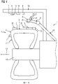
- the tire 1 has a tire surface 2 , the tire surface 2 having at least one bud 3 .
- the tire 1 is shown in a radial sectional view and is rotatable about an axis of rotation 13 in a direction of rotation 14 .
- At least one first burst 3 is located between two tread blocks 16 of a tread 15 of the tire 1.
- At least one second burst 3 is located on a sidewall 17 of the tire 1.
- a processing device 4 is provided for removing sprouts 3 on the tire surface 2 .
- the processing device 4 has a control component 5 , with the control component 5 being able to regulate the removal of the sprouts 3 by means of the processing device 4 depending on information about a sprout 3 on the tire surface 2 .
- a measuring device 6 is provided for measuring the tire surface 2 , the at least one expulsion 3 being measured by means of the measuring device 6 and information about the at least one expulsion 3 being generated and this information being transmittable to the control component 5 .
- a signal is generated by means of measuring device 6, the signal containing the information about the at least one bud 3, and this signal is transmitted by means of measuring device 6 to control component 5 and the at least one bud 3 by means of processing device 4 depending on the Information about the at least one shoot 3 is removed.
- the measuring device 6 has, in particular, means 7 for signal transmission.
- the control component 5 also has means 20 for signal transmission.
- the means 7 and 20 are preferably provided for a bidirectional exchange of signals, in particular via radio.
- the control component 5 is provided, in particular, for evaluating the signals transmitted to the means 20 and the information conveyed thereby about the at least one shoot 3 by means of an evaluation means 21 .
- the measuring device 6 has in particular a measuring component 12 .
- the measurement component 12 is, for example, a stereo camera, a light section component, a structured light projector component or a contour measurement component.
- the processing device 4 can be a laser device, for example.
- the laser device then has, in particular, beam guidance means 8 .
- the tire surface 2 and/or the at least one bud 3 can be cooled with a cooling device 9 before the at least one bud 3 is removed by means of the processing device 4 .
- the tire surface 2 can be cleaned with a cleaning device 10 after the at least one expulsion 3 has been removed.
- the processing device 4, the measuring device 6, the cooling device 9 and the cleaning device 10 are according to in FIG figure 1 illustrated embodiment part of a robot device 11, wherein the robot device 11 is provided for carrying out a method according to the invention.
- the processing device 4, the measuring device 6, the cooling device 9 and the cleaning device 10 are according to in FIG figure 1 illustrated embodiment on robot arms 18 of the robot device 11 arranged.
- the tire 1 is in accordance with the figure 1 illustrated embodiment is arranged on a tire holding component 19 of the robotic device 11 .
Landscapes
- Engineering & Computer Science (AREA)
- Mechanical Engineering (AREA)
- Tyre Moulding (AREA)
Abstract
Description
- Die Erfindung betrifft ein Verfahren zur Bearbeitung eines Reifens, einen Reifen und eine Robotervorrichtung.
- Die Erfindung geht aus von einem Verfahren zur Bearbeitung eines Reifens, aufweisend die folgenden Schritte:
- Bereitstellen eines Reifens, wobei der Reifen eine Reifenoberfläche aufweist, wobei die Reifenoberfläche mindestens einen Austrieb aufweist;
- Bereitstellen einer Bearbeitungsvorrichtung, wobei die Bearbeitungsvorrichtung zum Entfernen von Austrieben auf der Reifenoberfläche vorgesehen ist und wobei die Bearbeitungsvorrichtung eine Regelungskomponente aufweist, wobei mittels der Regelungskomponente die Entfernung der Austriebe mittels der Bearbeitungsvorrichtung in Abhängigkeit einer Information über einen Austrieb auf der Reifenoberfläche geregelt werden kann;
- Bereitstellen einer Vermessungsvorrichtung, wobei die Vermessungsvorrichtung zur Vermessung der Reifenoberfläche vorgesehen ist.
- Aus dem Stand der Technik sind Verfahren zur Bearbeitung von Reifen bekannt. Insbesondere ist es bekannt, Austriebe von Reifenoberflächen zu entfernen.
- Austriebe auf Reifenoberflächen werden beispielsweise während Vulkanisationsprozessen und Formgebungsprozessen von Reifen erzeugt. Im Vulkanisationsprozess entstehen beispielsweise an Segmentgrenzen der Vulkanisationsformen oder in einigen Entlüftungsbohrungen der Vulkanisationsform Austriebe auf der Reifenoberfläche. Die Austriebe sind aus dem Reifenkautschuk oder dem Reifengummimaterial ausgebildet und mit dem angrenzenden Gummimaterial oder Kautschukmaterial des Reifens verbunden. Die Austriebe können an verschiedenen Bereichen der Reifenoberfläche, beispielsweise an einem Laufstreifen des Reifens oder der Seitenwand des Reifens, entstehen.
- Bei den aus dem Stand der Technik bekannten Verfahren zum Bearbeiten von Reifen wird beispielsweise ein menschlicher Bediener eingesetzt, der die Reifenoberfläche visuell inspiziert und prüft, ob und wo sich auf der der Reifenoberfläche Austriebe befinden. In Abhängigkeit dieser visuellen Inspektion wird die Entfernung des Austriebs mittels der Bearbeitungsvorrichtung vorgenommen.
- Der Einsatz menschlicher Bediener für eine Bearbeitung des Reifens ist nicht optimal und kann im Vergleich zu einem vollständig automatisierten Verfahren zur Bearbeitung des Reifens langsamer und ungenauer erfolgen. Insbesondere muss beispielsweise für den Fall, wonach der Austrieb mittels einer Laservorrichtung entfernt werden soll, präzise der Ort oder die Position des Austriebs auf der Reifenoberfläche, sowie seine Abmessungen oder seine geometrische Form bestimmt werden. Auch für den Fall, wonach Austriebe zwischen Profilblöcken eines Laufstreifens des Reifens ausgebildet sind und diese Austriebe mittels einer Laservorrichtung entfernt werden sollen, ist eine präzise, rasche und zuverlässige Bestimmung des Orts oder der Position des Austriebs auf der Reifenoberfläche und eine präzise, rasche und zuverlässige Bestimmung der Abmessungen oder der Geometrie des Austriebs erforderlich. Die zuverlässige und genaue Bestimmung der Position, sowie der geometrischen Form oder der Abmessungen ist erforderlich, da beispielsweise im Fall einer Verwendung einer Laservorrichtung die Gefahr von Beschädigungen von Kautschukbereichen oder Gummimaterialbereichen des Reifens bestünde, die nicht zu dem Austrieb gehören.
- Der Erfindung liegt somit die Aufgabe zu Grunde ein Verfahren bereitzustellen, bei dem die Bearbeitung des Reifens und insbesondere die Entfernung von Austrieben automatisch erfolgt oder automatisch erfolgen kann.
- Gelöst wird die Aufgabe dadurch, dass das Verfahren durch den folgenden weiteren Schritt gekennzeichnet ist:
Vermessen der Reifenoberfläche mittels der Vermessungsvorrichtung, wobei mittels der Vermessungsvorrichtung der mindestens eine Austrieb vermessen wird und eine Information über den mindestens einen Austrieb erzeugt wird und wobei diese Information an die Regelungskomponente übertragbar ist. - Der mindestens eine Austrieb ist Bestandteil der Reifenoberfläche. Mittels des Vermessens der Reifenoberfläche kann somit auch der mindestens eine Austrieb vermessen werden. Mittels des Vermessens können beispielsweise ein Ort des mindestens einen Austriebs auf der Reifenoberfläche, eine geometrische Form des mindestens einen Austriebs und/oder Abmessungen des mindestens einen Austriebs bestimmt werden. Der Ort des mindestens einen Austriebs auf der Reifenoberfläche kann auch als die räumliche Position des mindestens einen Austriebs auf der Reifenoberfläche bezeichnet werden.
- Die Vermessungsvorrichtung weist insbesondere eine computerimplementierte künstliche-Intelligenz-Komponente auf, mittels der beispielsweise ein Ort des mindestens einen Austriebs auf der Reifenoberfläche, eine geometrische Form des mindestens einen Austriebs und/oder Abmessungen des mindestens einen Austriebs bestimmt werden können. Die Vermessungsvorrichtung weist zusätzlich oder alternativ insbesondere eine computerimplementierte künstliche-neuronale-Netz-Komponente auf, mittels der beispielsweise ein Ort des mindestens einen Austriebs auf der Reifenoberfläche, eine geometrische Form des mindestens einen Austriebs und/oder Abmessungen des mindestens einen Austriebs bestimmt werden können. Die Vermessungsvorrichtung weist zusätzlich oder alternativ insbesondere eine computerimplementierte reinforcement-learning-Komponente auf, mittels der beispielsweise ein Ort des mindestens einen Austriebs auf der Reifenoberfläche, eine geometrische Form des mindestens einen Austriebs und/oder Abmessungen des mindestens einen Austriebs bestimmt werden können.
- Die Information wird mittels der Vermessungsvorrichtung erzeugt und ist insbesondere elektromagnetisch, elektrisch oder elektronisch übertragbar. Die Information ist insbesondere auswertbar und speicherbar und insbesondere elektronisch, elektromagnetisch oder computergestützt auswertbar und speicherbar Durch den erfindungsgemäßen Umstand, wonach das Verfahren durch den folgenden weiteren Schritt gekennzeichnet ist:
- Vermessen der Reifenoberfläche mittels der Vermessungsvorrichtung, wobei mittels der Vermessungsvorrichtung der mindestens eine Austrieb vermessen wird und eine Information über den mindestens einen Austrieb erzeugt wird und wobei diese Information an die Regelungskomponente übertragbar ist; wird auf Grund der übertragbaren und insbesondere elektronisch oder elektromagnetisch auswertbaren Information eine automatisierte Regelung des Verfahrens ermöglicht. Ferner wird eine Dokumentation von Prozessschritten oder Prozessstadien des Verfahrens möglich. Diese Dokumentation ist möglich, weil die Information insbesondere speicherbar ist. Das erfindungsgemäße Verfahren lässt sich zudem in einen kontinuierlichen Prozess des Verfahrens implementieren und nimmt somit keine eigene Zeit in Anspruch, die zu einer Verzögerung des Verfahrens führen könnte.
- Somit wird ein verbessertes Verfahren zur Bearbeitung eines Reifens und insbesondere zum Entfernen von Austrieben bereitgestellt, bei dem eine automatisierte Regelung des Verfahrens möglich ist.
- Die Erfindung betrifft ferner einen Reifen, wobei der gemäß einem erfindungsgemäßen Verfahren bearbeitet worden ist. Bei dem Reifen handelt es sich beispielsweise um einen PKW-Reifen, um einen LKW-Reifen oder um einen Zweirad-Reifen. Ein erfindungsgemäß bearbeiteter Reifen weist verbesserte Fahreigenschaften beispielsweise im Hinblick auf Aquaplaning auf, da etwaige Austriebe im Bereich des Laufstreifens zuverlässig und vollständig entfernt worden sind. Ein solcher Reifen weist zudem eine, im Vergleich zu aus dem Stand der Technik bekannten Reifen, geringere Geräuschentwicklung während eines Abrollens auf einer Fahrbahn auf. Hintergrund der geringeren Geräuschentwicklung ist der Umstand, dass Austriebe vollständig und zuverlässig entfernt worden sind; Austriebe könnten während des Abrollens des Reifens zu Geräuschen führen.
- Die Erfindung betrifft ferner eine Robotervorrichtung, wobei die Robotervorrichtung zur Durchführung eines erfindungsgemäßen Verfahrens vorgesehen ist und insbesondere eine Bearbeitungsvorrichtung, eine Vermessungsvorrichtung, eine Kühlvorrichtung und/oder eine Reinigungsvorrichtung aufweist.
- Weitere vorteilhafte Ausführungsformen der vorliegenden Erfindung sind Gegenstand der Unteransprüche.
- Gemäß einer vorzugsweisen Ausgestaltungsform der vorliegenden Erfindung wird mittels der Vermessungsvorrichtung ein Signal erzeugt, wobei das Signal die Information über den mindestens einen Austrieb enthält, und dieses Signal mittels der Vermessungsvorrichtung an die Regelungskomponente übertragen wird und der mindestens eine Austrieb mittels der Bearbeitungsvorrichtung in Abhängigkeit der Information über den mindestens einen Austrieb entfernt wird.
- Die Vermessungsvorrichtung weist insbesondere Mittel zur Erzeugung des Signals und zur Übertragung des Signals auf. Die Übertragung des Signals erfolgt insbesondere elektrisch oder elektromagnetisch, also beispielsweise über ein Kabel oder über Funk.
- Die Regelungskomponente weist insbesondere ein Empfangsmittel und ein Auswertemittel zum Empfangen beziehungsweise Auswerten des Signals auf. Das Empfangsmittel der Regelungskomponente ist insbesondere zum Empfangen des Signals auf elektrische oder elektromagnetische Weise geeignet. Das Auswertemittel ist insbesondere geeignet, die Information, die mit dem Signal übertragen wird, zu verarbeiten und diese Information auszuwerten sowie für die Regelung der Bearbeitungsvorrichtung zu verwenden. Die Regelung der Bearbeitungsvorrichtung betrifft insbesondere die Betriebsparameter der Betriebsvorrichtung. Darüber hinaus kann bestimmt werden, in welchen Umfang mittels der Bearbeitungsvorrichtung auf einen Austrieb des Reifens zur Entfernung des Austriebs eingewirkt wird.
- Gemäß einer nächsten vorzugsweisen Ausgestaltungsform der vorliegenden Erfindung handelt es sich bei der Information über den mindestens einen Austrieb um eine Information über einen Ort des mindestens einen Austriebs auf der Reifenoberfläche und/oder um eine Information über Abmessungen des mindestens einen Austriebs und/oder um eine Information über eine Geometrie des mindestens einen Austriebs. Der Ort des mindestens einen Austriebs kann auch als die räumliche Position des mindestens einen Austriebs auf der Reifenoberfläche bezeichnet werden.
- Gemäß einer nächsten vorzugsweisen Ausgestaltungsform der vorliegenden Erfindung weist die Vermessungsvorrichtung eine Stereokamera auf, wobei die Vermessungsvorrichtung zur stereoskopischen Vermessung der Reifenoberfläche und des mindestens Austriebs vorgesehen ist und die Information über den mindestens einen Austrieb mittels der stereoskopischen Vermessung ermittelt wird. Gemäß einer nächsten vorzugsweisen Ausgestaltungsform der vorliegenden Erfindung weist die Vermessungsvorrichtung eine Lichtschnittkomponente auf, wobei die Vermessungsvorrichtung zur Vermessung der Reifenoberfläche und des mindestens Austriebs mittels eines Lichtschnittverfahrens vorgesehen ist und die Information über den mindestens einen Austrieb mittels des Lichtschnittverfahrens ermittelt wird.
- Gemäß einer nächsten vorzugsweisen Ausgestaltungsform der vorliegenden Erfindung weist die Vermessungsvorrichtung eine Streifenlichtprojektorkomponente auf, wobei die Vermessungsvorrichtung zur Vermessung der Reifenoberfläche und des mindestens Austriebs mittels eines Streifenlichtprojektionsverfahrens vorgesehen ist und die Information über den mindestens einen Austrieb mittels des Streifenlichtprojektionsverfahrens ermittelt wird. Die Streifenlichtprojektorkomponente weist einen Streifenlichtprojektor und ein aufnehmendes Element, beispielsweise eine Kamera oder einen Sensor, auf. Das aufnehmende Element dient der Erfassung und Aufnahme der mittels des Streifenlichtprojektors projizierten Lichteffekte
- Gemäß einer nächsten vorzugsweisen Ausgestaltungsform der vorliegenden Erfindung weist die Vermessungsvorrichtung eine Konturvermessungskomponente auf, wobei die Vermessungsvorrichtung zur Vermessung der Reifenoberfläche und des mindestens Austriebs mittels einer Konturvermessung vorgesehen ist und die Information über den mindestens einen Austrieb mittels der Konturvermessung ermittelt wird. Insbesondere wird eine Konturvermessung der Reifenoberfläche vorgenommen, wobei tangential zu der Reifenoberfläche vermessen wird. Dabei können beispielsweise Hintergrundbilder erzeugt werden, wobei über einen Vergleich der Hintergrundbilder, etwa beispielsweise über eine Subtraktion von Hintergrundwerten und Hintergrundbildinformationen der Hintergrundbilder, Unregelmäßigkeiten der Kontur der Reifenoberfläche ermittelt werden können. Grundsätzlich folgt der Reifen einer Rotationsymmetrie.
- Es können beispielsweise kontinuierlich während einer Rotation des Reifens auf einem dazu vorgesehenen Rotationsmittel die Außenkonturen des Reifens, also seine Umrisse, vor einem bekannten Hintergrund, beispielsweise einem Schirm, erfasst werden.
- Unregelmäßigkeiten, die von der erwartbaren Rotationssymmetrie abweichen, können zur Bestimmung von Austrieben auf der Reifenoberfläche verwendet werden. Auf Grundlage der Unregelmäßigkeiten kann die Information über den mindestens einen Austrieb erzeugt werden und diese Information wird insbesondere auf Basis dieser Unregelmäßigkeiten erzeugt.
- Gemäß einer nächsten vorzugsweisen Ausgestaltungsform der vorliegenden Erfindung wird mittels der Vermessungsvorrichtung ein dreidimensionales Abbild des Reifens und der Reifenoberfläche erzeugt. Anhand des dreidimensionalen Abbildes des Reifens und der Reifenoberfläche können die räumliche Position eines Austriebs auf der Reifenoberfläche und/oder die Abmessungen eines Austriebs auf der Reifenoberfläche oder eine geometrische Form eines Austriebs auf der Reifenoberfläche bestimmt und ermittelt werden. Dabei handelte sich insbesondere um die räumliche Position, die Abmessungen oder die geometrische Form des mindestens einen Austriebs der von der Reifenoberfläche entfernt wird oder entfernt werden soll. Auf Grundlage des dreidimensionalen Abbilds des Reifens und der Reifenoberfläche kann die Information über den mindestens einen Austrieb erzeugt werden und diese Information wird insbesondere auf Basis dieses dreidimensionalen Abbilds des Reifens und der Reifenoberfläche erzeugt.
- Gemäß einer nächsten vorzugsweisen Ausgestaltungsform der vorliegenden Erfindung handelt es sich bei der Bearbeitungsvorrichtung um eine Schneidevorrichtung oder um eine thermisch wirkende Vorrichtung oder um eine Bürstenvorrichtung oder um eine Schleifvorrichtung oder um eine Laservorrichtung oder um eine Materialstrahlvorrichtung. Bei der Materialstrahlvorrichtung handelt es sich insbesondere um eine Trockeneistrahlvorrichtung, also eine Vorrichtung, mittels der ein Strahl von Trockeneis auf einen Austrieb gerichtet werden kann. Bei dem Trockeneis, dass mittels der Trockeneisstrahlvorrichtung als Strahl auf einen Austrieb gerichtet werden kann, handelt es sich beispielsweise um Trockeneispellets, vorzugsweise um Pellets aus gefrorenem Stickstoff. Bei der Materialstrahlvorrichtung handelt es sich insbesondere um eine Sandstrahlvorrichtung, also eine Vorrichtung, mittels der ein Strahl von Sand auf einen Austrieb gerichtet werden kann. Bei der Materialstrahlvorrichtung handelt es sich insbesondere um eine Glasperlenstrahlvorrichtung, also eine Vorrichtung, mittels der ein Strahl von Glasperlen auf einen Austrieb gerichtet werden kann. Bei der Materialstrahlvorrichtung handelt es sich insbesondere um eine Stahlgriesstrahlvorrichtung, also eine Vorrichtung, mittels der ein Strahl von Stahlgries auf einen Austrieb gerichtet werden kann.
- Bei der Schleifvorrichtung kann es sich insbesondere um einen Druckluftschleifer oder um einen Elektroschleifer handeln. Die jeweilige Bearbeitungsvorrichtung ist zum Abtrennen oder Entfernen des einen Austriebes geeignet. Mittels der Schneidevorrichtung kann der mindestens eine Austrieb beispielsweise von dem Gummimaterial des Reifens abgeschnitten werden. Mittels der Schleifvorrichtung kann der mindestens eine Austrieb beispielsweise von dem Gummimaterial des Reifens beispielsweise abgeschliffen werden. Mittels der thermisch wirkenden Vorrichtung kann der mindestens eine Austrieb beispielsweise von dem Gummimaterial des Reifens beispielsweise weggebrannt oder weggeschmolzen werden. Mittels der Bürstenvorrichtung kann der mindestens eine Austrieb beispielsweise von dem Gummimaterial des Reifens beispielsweise weggerieben werden. Mittels der Laservorrichtung kann der mindestens eine Austrieb beispielsweise von dem Gummimaterial des Reifens beispielsweise weggebrannt oder weggeschmolzen oder weggeschnitten werden. Mittels der Materialstrahlvorrichtung kann der mindestens eine Austrieb beispielsweise von dem Gummimaterial des Reifens beispielsweise weggerieben oder weggeschnitten werden.
- Gemäß einer nächsten vorzugsweisen Ausgestaltungsform der vorliegenden Erfindung weist die Laservorrichtung, für den Fall, wonach es sich bei der Bearbeitungsvorrichtung um eine Laservorrichtung handelt, Strahlführungsmittel auf. Bei den Strahlführungsmitteln handelt es sich beispielsweise um Mittel, die mittels Spiegel oder mittels eines Lichtwellenleiters die Laserstrahlen führen können. Der Einsatz von Strahlführungsmitteln ist insbesondere von Vorteil, wenn Austriebe entfernt werden sollen, die sich zwischen Profilblöcken befinden.
- Für den Fall, wonach es sich bei der Bearbeitungsvorrichtung um die Laservorrichtung handelt, handelt es sich bei dem Betriebsparameter beispielsweise um die Intensität eines Lasers der Laservorrichtung oder um einen Winkel unter dem ein Laserstrahl der Laservorrichtung zu einem Normalvektor der Reifenoberfläche auf den mindestens einen Austrieb gerichtet wird. Dabei handelt es sich insbesondere um den Normalvektor des Bereichs der Reifenoberfläche an der der mindestens Austrieb sich befindet. Der Laserstrahl wird insbesondere tangential zu diesem Bereich der Reifenoberfläche, also in einem Winkel von 90° zu dem Normalvektor, auf einen direkten Übergangsbereich des mindestens einen Austriebs zu der Reifenoberfläche gerichtet. Somit ist ein unmittelbares und weitestmögliches Abtrennen des mindestens einen Austriebs von der Reifenoberfläche durchführbar.
- Gemäß einer nächsten vorzugsweisen Ausgestaltungsform der vorliegenden Erfindung wird eine Kühlvorrichtung bereitgestellt und die Reifenoberfläche und/oder der mindestens eine Austrieb werden mittels der Kühlvorrichtung gekühlt, bevor der mindestens eine Austrieb mittels der Bearbeitungsvorrichtung entfernt wird. Die Reifenoberfläche und/oder der mindestens eine Austrieb werden beispielsweise in einem Verfahrensschritt auf eine Oberflächentemperatur von -30° C bis -50° C gekühlt, insbesondere mittels einer Flüssigstickstoffkühlvorrichtung, bevor der mindestens eine Austrieb mittels der Bearbeitungsvorrichtung entfernt wird.
- Durch den erfindungsgemäßen Umstand, wonach die Reifenoberfläche und/oder der mindestens eine Austrieb mittels der Kühlvorrichtung gekühlt werden, bevor der mindestens eine Austrieb mittels der Bearbeitungsvorrichtung entfernt wird, kann insbesondere eine mechanische Entfernung des mindestens einen Austriebs, beispielsweise mittels einer Schneidevorrichtung, einer Bürstenvorrichtung, einer Schleifvorrichtung oder einer Materialstrahlvorrichtung energiesparender vorgenommen werden, als es ohne eine solche Kühlung der Fall wäre. Hintergrund ist, dass das Gummimaterial und insbesondere das Kautschukmaterial, aus dem der mindestens eine Austrieb ausgebildet ist, unter Einwirkung der Kühlung leichter mechanisch bearbeitet und abgetrennt werden kann.
- Gemäß einer nächsten vorzugsweisen Ausgestaltungsform der vorliegenden Erfindung wird eine Reinigungsvorrichtung bereitgestellt und die Reifenoberfläche wird nach dem Entfernen des mindestens einen Austriebs mittels der Reinigungsvorrichtung gereinigt.
- Gemäß einer nächsten vorzugsweisen Ausgestaltungsform der vorliegenden Erfindung handelt es sich bei der Reinigungsvorrichtung um eine Gebläsevorrichtung oder um eine Saugvorrichtung oder um eine Bürstenvorrichtung.
- Weitere Merkmale, Vorteile und Einzelheiten, auf die die Erfindung in ihrem Umfang aber nicht beschränkt ist, werden nun anhand der Zeichnung näher beschrieben.
- Es zeigt:
Fig. 1 : Eine schematische Darstellung von Vorrichtungen zur Durchführung des erfindungsgemäßen Verfahrens, einen erfindungsgemäßen Reifen und eine erfindungsgemäße Robotervorrichtung. - In der
Figur 1 sind Vorrichtungen zur Durchführung eines erfindungsgemäßen Verfahrens schematisch dargestellt. Das erfindungsgemäße Verfahren ist zur Bearbeitung eines Reifens 1 vorgesehen. Der Reifen 1 weist eine Reifenoberfläche 2 auf, wobei die Reifenoberfläche 2 mindestens einen Austrieb 3 aufweist. Gemäß der Darstellung in derFigur 1 ist der Reifen 1 in Radialschnittansicht dargestellt und um eine Rotationsachse 13 in eine Umlaufrichtung 14 rotierbar. Gemäß der Darstellung in derFigur 1 befindet sich mindestens ein erster Austrieb 3 zwischen zwei Profilblöcken 16 eines Laufstreifens 15 des Reifens 1. Mindestens ein zweiter Austrieb 3 befindet sich an einer Seitenwand 17 des Reifens 1. - Eine Bearbeitungsvorrichtung 4 ist zum Entfernen von Austrieben 3 auf der Reifenoberfläche 2 vorgesehen. Die Bearbeitungsvorrichtung 4 weist eine Regelungskomponente 5 auf, wobei mittels der Regelungskomponente 5 die Entfernung der Austriebe 3 mittels der Bearbeitungsvorrichtung 4 in Abhängigkeit einer Information über einen Austrieb 3 auf der Reifenoberfläche 2 geregelt werden kann.
- Eine Vermessungsvorrichtung 6 ist zur Vermessung der Reifenoberfläche 2 vorgesehen, wobei mittels der Vermessungsvorrichtung 6 der mindestens eine Austrieb 3 vermessen wird und eine Information über den mindestens einen Austrieb 3 erzeugt wird und wobei diese Information an die Regelungskomponente 5 übertragbar ist.
- Mittels der Vermessungsvorrichtung 6 wird insbesondere ein Signal erzeugt wird, wobei das Signal die Information über den mindestens einen Austrieb 3 enthält, und dieses Signal mittels der Vermessungsvorrichtung 6 an die Regelungskomponente 5 übertragen wird und der mindestens eine Austrieb 3 mittels der Bearbeitungsvorrichtung 4 in Abhängigkeit der Information über den mindestens einen Austrieb 3 entfernt wird. Die Vermessungsvorrichtung 6 weist zur Übertragung von Signalen insbesondere Mittel 7 zur Signalübertragung auf.
- Die Regelungskomponente 5 weist ebenfalls Mittel 20 zur Signalübertragung auf. Die Mittel 7 und 20 sind vorzugsweise zu einem bidirektionalen Austausch von Signalen, insbesondere über Funk, vorgesehen. Die Regelungskomponente 5 ist insbesondere zu einem Auswerten der zu dem Mittel 20 übertragenen Signale und der damit transportierten Information über den mindestens einen Austrieb 3 mittels eines Auswertemittels 21 vorgesehen.
- Die Vermessungsvorrichtung 6 weist insbesondere eine Vermessungskomponente 12 auf. Bei der Vermessungskomponente 12 handelt es sich beispielsweise um eine Stereokamera, eine Lichtschnittkomponente, eine Streifenlichtprojektorkomponente oder um eine Konturvermessungskomponente. Bei der Bearbeitungsvorrichtung 4 kann es sich beispielsweise um eine Laservorrichtung handeln. Die Laservorrichtung weist dann insbesondere Strahlführungsmittel 8 auf.
- Mit einer Kühlvorrichtung 9 können die Reifenoberfläche 2 und/oder der mindestens eine Austrieb 3 gekühlt werden, bevor der mindestens eine Austrieb 3 mittels der Bearbeitungsvorrichtung 4 entfernt wird.
- Mit einer Reinigungsvorrichtung 10 kann die Reifenoberfläche 2 nach dem Entfernen des mindestens einen Austriebs 3 gereinigt werden.
- Die Bearbeitungsvorrichtung 4, die Vermessungsvorrichtung 6, die Kühlvorrichtung 9 und die Reinigungsvorrichtung 10 sind gemäß der in der
Figur 1 dargestellten Ausführungsform Bestandteil einer Robotervorrichtung 11, wobei die Robotervorrichtung 11 zur Durchführung eines erfindungsgemäßen Verfahrens vorgesehen ist. Die Bearbeitungsvorrichtung 4, die Vermessungsvorrichtung 6, die Kühlvorrichtung 9 und die Reinigungsvorrichtung 10 sind gemäß der in derFigur 1 dargestellten Ausführungsform an Roboterarmen 18 der Robotervorrichtung 11 angeordnet. Der Reifen 1 ist gemäß der in derFigur 1 dargestellten Ausführungsform an einer Reifenhaltekomponente 19 der Robotervorrichtung 11 angeordnet. -
- 1
- Reifen
- 2
- Reifenoberfläche
- 3
- Austrieb
- 4
- Bearbeitungsvorrichtung
- 5
- Regelungskomponente
- 6
- Vermessungsvorrichtung
- 7
- Mittel zur Signalübertragung
- 8
- Strahlführungsmittel
- 9
- Kühlvorrichtung
- 10
- Reinigiungsvorrichtung
- 11
- Robotervorrichtung
- 12
- Vermessungskomponente
- 13
- Rotationsachse
- 14
- Umlaufrichtung
- 15
- Laufstreifen
- 16
- Profilblöcken
- 17
- Seitenwand
- 18
- Roboterarme
- 19
- Reifenhaltekomponente
- 20
- Mittel zur Signalübertragung
- 21
- Auswertemittel
Claims (11)
- Verfahren zur Bearbeitung eines Reifens (1), aufweisend die folgenden Schritte:- Bereitstellen eines Reifens (1), wobei der Reifen (1) eine Reifenoberfläche (2) aufweist, wobei die Reifenoberfläche (2) mindestens einen Austrieb (3) aufweist;- Bereitstellen einer Bearbeitungsvorrichtung (4), wobei die Bearbeitungsvorrichtung (4) zum Entfernen von Austrieben (3) auf der Reifenoberfläche (2) vorgesehen ist und wobei die Bearbeitungsvorrichtung (4) eine Regelungskomponente (5) aufweist, wobei mittels der Regelungskomponente (5) die Entfernung der Austriebe (3) mittels der Bearbeitungsvorrichtung (4) in Abhängigkeit einer Information über einen Austrieb (3) auf der Reifenoberfläche (2) geregelt werden kann; wobei das Verfahren durch die weiteren Schritte gekennzeichnet ist:- Bereitstellen einer Vermessungsvorrichtung (6), wobei die Vermessungsvorrichtung (6) zur Vermessung der Reifenoberfläche (2) vorgesehen ist;- Vermessen der Reifenoberfläche (2) mittels der Vermessungsvorrichtung (6), wobei mittels der Vermessungsvorrichtung (3) der mindestens eine Austrieb (3) vermessen wird und eine Information über den mindestens einen Austrieb (3) erzeugt wird und wobei diese Information an die Regelungskomponente (5) übertragbar ist.
- Verfahren nach Anspruch 1, dadurch gekennzeichnet, dass mittels der Vermessungsvorrichtung (6) ein Signal erzeugt wird, wobei das Signal die Information über den mindestens einen Austrieb (3) enthält, und dieses Signal mittels der Vermessungsvorrichtung (6) an die Regelungskomponente (5) übertragen wird und der mindestens eine Austrieb (3) mittels der Bearbeitungsvorrichtung (4) in Abhängigkeit der Information über den mindestens einen Austrieb (3) entfernt wird.
- Verfahren nach Anspruch 1, dadurch gekennzeichnet, dass es sich bei der Information über den mindestens einen Austrieb (3) um eine Information über einen Ort des mindestens einen Austriebs (3) auf der Reifenoberfläche (2) und/oder um eine Information über Abmessungen des mindestens einen Austriebs (3) und/oder um eine Information über eine Geometrie des mindestens einen Austriebs (3) handelt.
- Verfahren nach einem der vorhergehenden Ansprüche, dadurch gekennzeichnet, dass die Vermessungsvorrichtung (6) eine Stereokamera (12) aufweist, wobei die Vermessungsvorrichtung (6) zur stereoskopischen Vermessung der Reifenoberfläche (2) und des mindestens Austriebs (3) vorgesehen ist und die Information über den mindestens einen Austrieb (3) mittels der stereoskopischen Vermessung ermittelt wird oder, dass die Vermessungsvorrichtung (6) eine Lichtschnittkomponente (12) aufweist, wobei die Vermessungsvorrichtung (6) zur Vermessung der Reifenoberfläche (2) und des mindestens Austriebs (3) mittels eines Lichtschnittverfahrens vorgesehen ist und die Information über den mindestens einen Austrieb (3) mittels des Lichtschnittverfahrens ermittelt wird oder, dass die Vermessungsvorrichtung (6) eine Streifenlichtprojektorkomponente (12) aufweist, wobei die Vermessungsvorrichtung (6) zur Vermessung der Reifenoberfläche (2) und des mindestens Austriebs (3) mittels eines Streifenlichtprojektionsverfahrens vorgesehen ist und die Information über den mindestens einen Austrieb (3) mittels des Streifenlichtprojektionsverfahrens ermittelt wird oder, dass die Vermessungsvorrichtung (6) eine Konturvermessungskomponente (12) aufweist, wobei die Vermessungsvorrichtung (6) zur Vermessung der Reifenoberfläche (2) und des mindestens Austriebs (3) mittels einer Konturvermessung vorgesehen ist und die Information über den mindestens einen Austrieb (3) mittels der Konturvermessung ermittelt wird.
- Verfahren nach einem der vorhergehenden Ansprüche, dadurch gekennzeichnet, dass es sich bei der Bearbeitungsvorrichtung (4) um eine Schneidevorrichtung oder um eine thermisch wirkende Vorrichtung oder um eine Bürstenvorrichtung oder um eine Schleifvorrichtung oder um eine Laservorrichtung, oder um eine Materialstrahlvorrichtung handelt.
- Verfahren nach dem vorhergehenden Anspruch, dadurch gekennzeichnet, dass es sich für den Fall, wonach es bei der Bearbeitungsvorrichtung (4) um einen Laservorrichtung handelt, die Laservorrichtung Strahlführungsmittel (8) aufweist.
- Verfahren nach einem der vorhergehenden Ansprüche, dadurch gekennzeichnet, dass eine Kühlvorrichtung (9) bereitgestellt wird und die Reifenoberfläche (2) und/oder der mindestens eine Austrieb (3) mittels der Kühlvorrichtung (9) gekühlt werden, bevor der mindestens eine Austrieb (3) mittels der Bearbeitungsvorrichtung (4) entfernt wird.
- Verfahren nach einem der vorhergehenden Ansprüche, dadurch gekennzeichnet, dass eine Reinigungsvorrichtung (10) bereitgestellt wird und die Reifenoberfläche (2) nach dem Entfernen des mindestens einen Austriebs (3) mittels der Reinigungsvorrichtung (10) gereinigt wird.
- Verfahren nach dem vorhergehenden Anspruch, dadurch gekennzeichnet, dass es sich bei der Reinigungsvorrichtung (10) um eine Gebläsevorrichtung oder um eine Saugvorrichtung oder um eine Bürstenvorrichtung handelt.
- Reifen (1), wobei der Reifen (1) gemäß einem Verfahren gemäß einem der vorhergehenden Ansprüche bearbeitet worden ist.
- Robotervorrichtung (11), wobei die Robotervorrichtung (11) zur Durchführung eines Verfahrens nach einem der Ansprüche 1 bis 9 vorgesehen ist und insbesondere eine Bearbeitungsvorrichtung (4), eine Vermessungsvorrichtung (6), eine Kühlvorrichtung (9) und/oder eine Reinigungsvorrichtung (10) aufweist.
Applications Claiming Priority (1)
| Application Number | Priority Date | Filing Date | Title |
|---|---|---|---|
| DE102021204892.7A DE102021204892A1 (de) | 2021-05-14 | 2021-05-14 | Verfahren zur Bearbeitung eines Reifens |
Publications (2)
| Publication Number | Publication Date |
|---|---|
| EP4088918A1 true EP4088918A1 (de) | 2022-11-16 |
| EP4088918B1 EP4088918B1 (de) | 2024-02-14 |
Family
ID=78695529
Family Applications (1)
| Application Number | Title | Priority Date | Filing Date |
|---|---|---|---|
| EP21208900.7A Active EP4088918B1 (de) | 2021-05-14 | 2021-11-18 | Verfahren zur bearbeitung eines reifens |
Country Status (2)
| Country | Link |
|---|---|
| EP (1) | EP4088918B1 (de) |
| DE (1) | DE102021204892A1 (de) |
Citations (3)
| Publication number | Priority date | Publication date | Assignee | Title |
|---|---|---|---|---|
| JP2014004793A (ja) * | 2012-06-26 | 2014-01-16 | Bridgestone Corp | スピューの除去方法 |
| DE102019212080A1 (de) * | 2019-08-13 | 2021-02-18 | Continental Reifen Deutschland Gmbh | Verfahren zum automatisierten Identifizieren und Entfernen von Materialaustrieben an einem Fahrzeugreifen |
| DE102019217169A1 (de) * | 2019-11-07 | 2021-05-12 | Continental Reifen Deutschland Gmbh | Verfahren zum automatisierten Identifizieren und Entfernen von Materialaustrieben an einem Fahrzeugreifen |
-
2021
- 2021-05-14 DE DE102021204892.7A patent/DE102021204892A1/de not_active Withdrawn
- 2021-11-18 EP EP21208900.7A patent/EP4088918B1/de active Active
Patent Citations (3)
| Publication number | Priority date | Publication date | Assignee | Title |
|---|---|---|---|---|
| JP2014004793A (ja) * | 2012-06-26 | 2014-01-16 | Bridgestone Corp | スピューの除去方法 |
| DE102019212080A1 (de) * | 2019-08-13 | 2021-02-18 | Continental Reifen Deutschland Gmbh | Verfahren zum automatisierten Identifizieren und Entfernen von Materialaustrieben an einem Fahrzeugreifen |
| DE102019217169A1 (de) * | 2019-11-07 | 2021-05-12 | Continental Reifen Deutschland Gmbh | Verfahren zum automatisierten Identifizieren und Entfernen von Materialaustrieben an einem Fahrzeugreifen |
Also Published As
| Publication number | Publication date |
|---|---|
| EP4088918B1 (de) | 2024-02-14 |
| DE102021204892A1 (de) | 2022-11-17 |
Similar Documents
| Publication | Publication Date | Title |
|---|---|---|
| DE102010026351B4 (de) | Verfahren und Vorrichtung zur Untersuchung einer Halbleiterscheibe | |
| DE69113712T2 (de) | Einrichtung zur Bestimmung des Abnutzungszustandes von Fahrzeugluftreifen. | |
| KR102078908B1 (ko) | 무인 차량을 이용한 자동화 차선 도색 시스템 | |
| CN103163144A (zh) | 用于在喷漆之前监视施加到机动车车身上的底漆层的质量的方法 | |
| WO2021037710A1 (de) | Verfahren und vorrichtung zur echtzeitbestimmung von eigenschaften einer von einem fahrzeug momentan befahrenen fahrbahn | |
| DE102021211888A1 (de) | Verfahren zur Klassierung der Oberflächentextur von Kautschukprodukten | |
| DE102016213059A1 (de) | Verfahren und Steuergerät zum Verarbeiten eines zumindest einen Lichthof repräsentierenden Bildes sowie Bildaufnahmesystem | |
| EP2837461B1 (de) | Verfahren zum Ermitteln eines Verschleißzustands einer Schneiddüse und Laserbearbeitungsmaschine zur Durchführung des Verfahrens | |
| EP4198894A1 (de) | Kamerabasierte fahrzeugkonturerfassung für fahrzeugbehandlungsanlagen | |
| EP4088918B1 (de) | Verfahren zur bearbeitung eines reifens | |
| DE102018121435A1 (de) | Vorrichtung zur Zustandserfassung von Altreifen | |
| WO2019015851A1 (de) | Verfahren und vorrichtung zum identifizieren von schäden in fahrzeugscheiben | |
| DE102020211954A1 (de) | Verfahren zum Laserstrahlreinigen von Bauteiloberflächen sowie Laserstrahlreinigungseinrichtung | |
| DE102011086091B4 (de) | Vorrichtung und Verfahren zum mechanischen Ausdünnen von Blüten | |
| DE102021002747A1 (de) | Gelenkarmroboter und Verfahren zur Überwachung und Instandsetzung von Bauteilen oder Baugruppen in einem 3D-Drucker | |
| DE102019202983A1 (de) | Verfahren zum Betrieb eines Kraftfahrzeugs | |
| EP3231555B1 (de) | Verfahren und vorrichtung zur ermittlung der schleiffähigkeit eines schleifwerkzeugs | |
| DE202019003042U1 (de) | Anordnung von Modulen zur 3D-gestützten optischen Inspektion von Rohrleitungen und Kanälen | |
| DE102019217169A1 (de) | Verfahren zum automatisierten Identifizieren und Entfernen von Materialaustrieben an einem Fahrzeugreifen | |
| EP3123140A1 (de) | Verfahren und vorrichtung zum überprüfen der reifenmontage an einem fahrzeug | |
| DE102015002663B4 (de) | Verfahren und Vorrichtung zum kostengünstigen Schneiden von Profilen in Fahrzeugreifen | |
| DE102021202157A1 (de) | Verfahren zum automatisierten Identifizieren und Entfernen von Materialaustrieben an einem Fahrzeugreifen | |
| DE102020210269A1 (de) | Verfahren zum Ermitteln von Fahrbahnbedingungen | |
| DE102010050279B4 (de) | Verfahren zum Gewinnen von Daten und zum Ausrichten eines Umfeldsensors eines Kraftwagens | |
| DE102024110611B3 (de) | Verfahren zur Inspektion eines Flugzeugs und System |
Legal Events
| Date | Code | Title | Description |
|---|---|---|---|
| PUAI | Public reference made under article 153(3) epc to a published international application that has entered the european phase |
Free format text: ORIGINAL CODE: 0009012 |
|
| STAA | Information on the status of an ep patent application or granted ep patent |
Free format text: STATUS: THE APPLICATION HAS BEEN PUBLISHED |
|
| AK | Designated contracting states |
Kind code of ref document: A1 Designated state(s): AL AT BE BG CH CY CZ DE DK EE ES FI FR GB GR HR HU IE IS IT LI LT LU LV MC MK MT NL NO PL PT RO RS SE SI SK SM TR |
|
| STAA | Information on the status of an ep patent application or granted ep patent |
Free format text: STATUS: REQUEST FOR EXAMINATION WAS MADE |
|
| 17P | Request for examination filed |
Effective date: 20230516 |
|
| RBV | Designated contracting states (corrected) |
Designated state(s): AL AT BE BG CH CY CZ DE DK EE ES FI FR GB GR HR HU IE IS IT LI LT LU LV MC MK MT NL NO PL PT RO RS SE SI SK SM TR |
|
| GRAP | Despatch of communication of intention to grant a patent |
Free format text: ORIGINAL CODE: EPIDOSNIGR1 |
|
| STAA | Information on the status of an ep patent application or granted ep patent |
Free format text: STATUS: GRANT OF PATENT IS INTENDED |
|
| RIC1 | Information provided on ipc code assigned before grant |
Ipc: G01B 11/24 20060101ALI20231004BHEP Ipc: G01B 11/22 20060101ALI20231004BHEP Ipc: G01M 17/02 20060101ALI20231004BHEP Ipc: B60C 25/00 20060101ALI20231004BHEP Ipc: B29D 30/06 20060101ALI20231004BHEP Ipc: B29D 30/00 20060101AFI20231004BHEP |
|
| INTG | Intention to grant announced |
Effective date: 20231019 |
|
| GRAS | Grant fee paid |
Free format text: ORIGINAL CODE: EPIDOSNIGR3 |
|
| GRAA | (expected) grant |
Free format text: ORIGINAL CODE: 0009210 |
|
| STAA | Information on the status of an ep patent application or granted ep patent |
Free format text: STATUS: THE PATENT HAS BEEN GRANTED |
|
| P01 | Opt-out of the competence of the unified patent court (upc) registered |
Effective date: 20231218 |
|
| AK | Designated contracting states |
Kind code of ref document: B1 Designated state(s): AL AT BE BG CH CY CZ DE DK EE ES FI FR GB GR HR HU IE IS IT LI LT LU LV MC MK MT NL NO PL PT RO RS SE SI SK SM TR |
|
| REG | Reference to a national code |
Ref country code: GB Ref legal event code: FG4D Free format text: NOT ENGLISH |
|
| REG | Reference to a national code |
Ref country code: CH Ref legal event code: EP |
|
| REG | Reference to a national code |
Ref country code: DE Ref legal event code: R096 Ref document number: 502021002684 Country of ref document: DE |
|
| RAP4 | Party data changed (patent owner data changed or rights of a patent transferred) |
Owner name: CONTINENTAL REIFEN DEUTSCHLAND GMBH |
|
| REG | Reference to a national code |
Ref country code: IE Ref legal event code: FG4D Free format text: LANGUAGE OF EP DOCUMENT: GERMAN |
|
| REG | Reference to a national code |
Ref country code: LT Ref legal event code: MG9D |
|
| REG | Reference to a national code |
Ref country code: NL Ref legal event code: MP Effective date: 20240214 |
|
| PG25 | Lapsed in a contracting state [announced via postgrant information from national office to epo] |
Ref country code: IS Free format text: LAPSE BECAUSE OF FAILURE TO SUBMIT A TRANSLATION OF THE DESCRIPTION OR TO PAY THE FEE WITHIN THE PRESCRIBED TIME-LIMIT Effective date: 20240614 |
|
| PG25 | Lapsed in a contracting state [announced via postgrant information from national office to epo] |
Ref country code: LT Free format text: LAPSE BECAUSE OF FAILURE TO SUBMIT A TRANSLATION OF THE DESCRIPTION OR TO PAY THE FEE WITHIN THE PRESCRIBED TIME-LIMIT Effective date: 20240214 |
|
| PG25 | Lapsed in a contracting state [announced via postgrant information from national office to epo] |
Ref country code: GR Free format text: LAPSE BECAUSE OF FAILURE TO SUBMIT A TRANSLATION OF THE DESCRIPTION OR TO PAY THE FEE WITHIN THE PRESCRIBED TIME-LIMIT Effective date: 20240515 |
|
| PG25 | Lapsed in a contracting state [announced via postgrant information from national office to epo] |
Ref country code: NL Free format text: LAPSE BECAUSE OF FAILURE TO SUBMIT A TRANSLATION OF THE DESCRIPTION OR TO PAY THE FEE WITHIN THE PRESCRIBED TIME-LIMIT Effective date: 20240214 Ref country code: HR Free format text: LAPSE BECAUSE OF FAILURE TO SUBMIT A TRANSLATION OF THE DESCRIPTION OR TO PAY THE FEE WITHIN THE PRESCRIBED TIME-LIMIT Effective date: 20240214 Ref country code: RS Free format text: LAPSE BECAUSE OF FAILURE TO SUBMIT A TRANSLATION OF THE DESCRIPTION OR TO PAY THE FEE WITHIN THE PRESCRIBED TIME-LIMIT Effective date: 20240514 |
|
| PG25 | Lapsed in a contracting state [announced via postgrant information from national office to epo] |
Ref country code: ES Free format text: LAPSE BECAUSE OF FAILURE TO SUBMIT A TRANSLATION OF THE DESCRIPTION OR TO PAY THE FEE WITHIN THE PRESCRIBED TIME-LIMIT Effective date: 20240214 |
|
| PG25 | Lapsed in a contracting state [announced via postgrant information from national office to epo] |
Ref country code: RS Free format text: LAPSE BECAUSE OF FAILURE TO SUBMIT A TRANSLATION OF THE DESCRIPTION OR TO PAY THE FEE WITHIN THE PRESCRIBED TIME-LIMIT Effective date: 20240514 Ref country code: NO Free format text: LAPSE BECAUSE OF FAILURE TO SUBMIT A TRANSLATION OF THE DESCRIPTION OR TO PAY THE FEE WITHIN THE PRESCRIBED TIME-LIMIT Effective date: 20240514 Ref country code: NL Free format text: LAPSE BECAUSE OF FAILURE TO SUBMIT A TRANSLATION OF THE DESCRIPTION OR TO PAY THE FEE WITHIN THE PRESCRIBED TIME-LIMIT Effective date: 20240214 Ref country code: LT Free format text: LAPSE BECAUSE OF FAILURE TO SUBMIT A TRANSLATION OF THE DESCRIPTION OR TO PAY THE FEE WITHIN THE PRESCRIBED TIME-LIMIT Effective date: 20240214 Ref country code: IS Free format text: LAPSE BECAUSE OF FAILURE TO SUBMIT A TRANSLATION OF THE DESCRIPTION OR TO PAY THE FEE WITHIN THE PRESCRIBED TIME-LIMIT Effective date: 20240614 Ref country code: HR Free format text: LAPSE BECAUSE OF FAILURE TO SUBMIT A TRANSLATION OF THE DESCRIPTION OR TO PAY THE FEE WITHIN THE PRESCRIBED TIME-LIMIT Effective date: 20240214 Ref country code: GR Free format text: LAPSE BECAUSE OF FAILURE TO SUBMIT A TRANSLATION OF THE DESCRIPTION OR TO PAY THE FEE WITHIN THE PRESCRIBED TIME-LIMIT Effective date: 20240515 Ref country code: FI Free format text: LAPSE BECAUSE OF FAILURE TO SUBMIT A TRANSLATION OF THE DESCRIPTION OR TO PAY THE FEE WITHIN THE PRESCRIBED TIME-LIMIT Effective date: 20240214 Ref country code: ES Free format text: LAPSE BECAUSE OF FAILURE TO SUBMIT A TRANSLATION OF THE DESCRIPTION OR TO PAY THE FEE WITHIN THE PRESCRIBED TIME-LIMIT Effective date: 20240214 Ref country code: BG Free format text: LAPSE BECAUSE OF FAILURE TO SUBMIT A TRANSLATION OF THE DESCRIPTION OR TO PAY THE FEE WITHIN THE PRESCRIBED TIME-LIMIT Effective date: 20240214 |
|
| PG25 | Lapsed in a contracting state [announced via postgrant information from national office to epo] |
Ref country code: PL Free format text: LAPSE BECAUSE OF FAILURE TO SUBMIT A TRANSLATION OF THE DESCRIPTION OR TO PAY THE FEE WITHIN THE PRESCRIBED TIME-LIMIT Effective date: 20240214 Ref country code: PT Free format text: LAPSE BECAUSE OF FAILURE TO SUBMIT A TRANSLATION OF THE DESCRIPTION OR TO PAY THE FEE WITHIN THE PRESCRIBED TIME-LIMIT Effective date: 20240614 |
|
| PG25 | Lapsed in a contracting state [announced via postgrant information from national office to epo] |
Ref country code: SE Free format text: LAPSE BECAUSE OF FAILURE TO SUBMIT A TRANSLATION OF THE DESCRIPTION OR TO PAY THE FEE WITHIN THE PRESCRIBED TIME-LIMIT Effective date: 20240214 Ref country code: PT Free format text: LAPSE BECAUSE OF FAILURE TO SUBMIT A TRANSLATION OF THE DESCRIPTION OR TO PAY THE FEE WITHIN THE PRESCRIBED TIME-LIMIT Effective date: 20240614 Ref country code: PL Free format text: LAPSE BECAUSE OF FAILURE TO SUBMIT A TRANSLATION OF THE DESCRIPTION OR TO PAY THE FEE WITHIN THE PRESCRIBED TIME-LIMIT Effective date: 20240214 Ref country code: LV Free format text: LAPSE BECAUSE OF FAILURE TO SUBMIT A TRANSLATION OF THE DESCRIPTION OR TO PAY THE FEE WITHIN THE PRESCRIBED TIME-LIMIT Effective date: 20240214 |
|
| PG25 | Lapsed in a contracting state [announced via postgrant information from national office to epo] |
Ref country code: DK Free format text: LAPSE BECAUSE OF FAILURE TO SUBMIT A TRANSLATION OF THE DESCRIPTION OR TO PAY THE FEE WITHIN THE PRESCRIBED TIME-LIMIT Effective date: 20240214 |
|
| PG25 | Lapsed in a contracting state [announced via postgrant information from national office to epo] |
Ref country code: SM Free format text: LAPSE BECAUSE OF FAILURE TO SUBMIT A TRANSLATION OF THE DESCRIPTION OR TO PAY THE FEE WITHIN THE PRESCRIBED TIME-LIMIT Effective date: 20240214 |
|
| PG25 | Lapsed in a contracting state [announced via postgrant information from national office to epo] |
Ref country code: EE Free format text: LAPSE BECAUSE OF FAILURE TO SUBMIT A TRANSLATION OF THE DESCRIPTION OR TO PAY THE FEE WITHIN THE PRESCRIBED TIME-LIMIT Effective date: 20240214 Ref country code: CZ Free format text: LAPSE BECAUSE OF FAILURE TO SUBMIT A TRANSLATION OF THE DESCRIPTION OR TO PAY THE FEE WITHIN THE PRESCRIBED TIME-LIMIT Effective date: 20240214 |
|
| PG25 | Lapsed in a contracting state [announced via postgrant information from national office to epo] |
Ref country code: SK Free format text: LAPSE BECAUSE OF FAILURE TO SUBMIT A TRANSLATION OF THE DESCRIPTION OR TO PAY THE FEE WITHIN THE PRESCRIBED TIME-LIMIT Effective date: 20240214 |
|
| PG25 | Lapsed in a contracting state [announced via postgrant information from national office to epo] |
Ref country code: SM Free format text: LAPSE BECAUSE OF FAILURE TO SUBMIT A TRANSLATION OF THE DESCRIPTION OR TO PAY THE FEE WITHIN THE PRESCRIBED TIME-LIMIT Effective date: 20240214 Ref country code: SK Free format text: LAPSE BECAUSE OF FAILURE TO SUBMIT A TRANSLATION OF THE DESCRIPTION OR TO PAY THE FEE WITHIN THE PRESCRIBED TIME-LIMIT Effective date: 20240214 Ref country code: RO Free format text: LAPSE BECAUSE OF FAILURE TO SUBMIT A TRANSLATION OF THE DESCRIPTION OR TO PAY THE FEE WITHIN THE PRESCRIBED TIME-LIMIT Effective date: 20240214 Ref country code: EE Free format text: LAPSE BECAUSE OF FAILURE TO SUBMIT A TRANSLATION OF THE DESCRIPTION OR TO PAY THE FEE WITHIN THE PRESCRIBED TIME-LIMIT Effective date: 20240214 Ref country code: DK Free format text: LAPSE BECAUSE OF FAILURE TO SUBMIT A TRANSLATION OF THE DESCRIPTION OR TO PAY THE FEE WITHIN THE PRESCRIBED TIME-LIMIT Effective date: 20240214 Ref country code: CZ Free format text: LAPSE BECAUSE OF FAILURE TO SUBMIT A TRANSLATION OF THE DESCRIPTION OR TO PAY THE FEE WITHIN THE PRESCRIBED TIME-LIMIT Effective date: 20240214 |
|
| REG | Reference to a national code |
Ref country code: DE Ref legal event code: R097 Ref document number: 502021002684 Country of ref document: DE |
|
| PG25 | Lapsed in a contracting state [announced via postgrant information from national office to epo] |
Ref country code: IT Free format text: LAPSE BECAUSE OF FAILURE TO SUBMIT A TRANSLATION OF THE DESCRIPTION OR TO PAY THE FEE WITHIN THE PRESCRIBED TIME-LIMIT Effective date: 20240214 |
|
| PLBE | No opposition filed within time limit |
Free format text: ORIGINAL CODE: 0009261 |
|
| STAA | Information on the status of an ep patent application or granted ep patent |
Free format text: STATUS: NO OPPOSITION FILED WITHIN TIME LIMIT |
|
| PG25 | Lapsed in a contracting state [announced via postgrant information from national office to epo] |
Ref country code: IT Free format text: LAPSE BECAUSE OF FAILURE TO SUBMIT A TRANSLATION OF THE DESCRIPTION OR TO PAY THE FEE WITHIN THE PRESCRIBED TIME-LIMIT Effective date: 20240214 |
|
| 26N | No opposition filed |
Effective date: 20241115 |
|
| PG25 | Lapsed in a contracting state [announced via postgrant information from national office to epo] |
Ref country code: SI Free format text: LAPSE BECAUSE OF FAILURE TO SUBMIT A TRANSLATION OF THE DESCRIPTION OR TO PAY THE FEE WITHIN THE PRESCRIBED TIME-LIMIT Effective date: 20240214 |
|
| REG | Reference to a national code |
Ref country code: CH Ref legal event code: PL |
|
| PG25 | Lapsed in a contracting state [announced via postgrant information from national office to epo] |
Ref country code: MC Free format text: LAPSE BECAUSE OF FAILURE TO SUBMIT A TRANSLATION OF THE DESCRIPTION OR TO PAY THE FEE WITHIN THE PRESCRIBED TIME-LIMIT Effective date: 20240214 |
|
| PG25 | Lapsed in a contracting state [announced via postgrant information from national office to epo] |
Ref country code: LU Free format text: LAPSE BECAUSE OF NON-PAYMENT OF DUE FEES Effective date: 20241118 |
|
| REG | Reference to a national code |
Ref country code: CH Ref legal event code: PL |
|
| PG25 | Lapsed in a contracting state [announced via postgrant information from national office to epo] |
Ref country code: CH Free format text: LAPSE BECAUSE OF NON-PAYMENT OF DUE FEES Effective date: 20241130 |
|
| REG | Reference to a national code |
Ref country code: BE Ref legal event code: MM Effective date: 20241130 |
|
| PG25 | Lapsed in a contracting state [announced via postgrant information from national office to epo] |
Ref country code: BE Free format text: LAPSE BECAUSE OF NON-PAYMENT OF DUE FEES Effective date: 20241130 |
|
| PG25 | Lapsed in a contracting state [announced via postgrant information from national office to epo] |
Ref country code: IE Free format text: LAPSE BECAUSE OF NON-PAYMENT OF DUE FEES Effective date: 20241118 |
|
| PGFP | Annual fee paid to national office [announced via postgrant information from national office to epo] |
Ref country code: DE Payment date: 20251130 Year of fee payment: 5 |
|
| PGFP | Annual fee paid to national office [announced via postgrant information from national office to epo] |
Ref country code: AT Payment date: 20260113 Year of fee payment: 5 |
|
| PGFP | Annual fee paid to national office [announced via postgrant information from national office to epo] |
Ref country code: FR Payment date: 20251126 Year of fee payment: 5 |
|
| PG25 | Lapsed in a contracting state [announced via postgrant information from national office to epo] |
Ref country code: HU Free format text: LAPSE BECAUSE OF FAILURE TO SUBMIT A TRANSLATION OF THE DESCRIPTION OR TO PAY THE FEE WITHIN THE PRESCRIBED TIME-LIMIT; INVALID AB INITIO Effective date: 20211118 |
|
| PG25 | Lapsed in a contracting state [announced via postgrant information from national office to epo] |
Ref country code: CY Free format text: LAPSE BECAUSE OF FAILURE TO SUBMIT A TRANSLATION OF THE DESCRIPTION OR TO PAY THE FEE WITHIN THE PRESCRIBED TIME-LIMIT; INVALID AB INITIO Effective date: 20211118 |