EP4087970B1 - Câble multi-torons à une couche à énergie à rupture améliorée et à allongement total amélioré - Google Patents
Câble multi-torons à une couche à énergie à rupture améliorée et à allongement total amélioré Download PDFInfo
- Publication number
- EP4087970B1 EP4087970B1 EP20845790.3A EP20845790A EP4087970B1 EP 4087970 B1 EP4087970 B1 EP 4087970B1 EP 20845790 A EP20845790 A EP 20845790A EP 4087970 B1 EP4087970 B1 EP 4087970B1
- Authority
- EP
- European Patent Office
- Prior art keywords
- cord
- cable
- helix
- strand
- metal
- Prior art date
- Legal status (The legal status is an assumption and is not a legal conclusion. Google has not performed a legal analysis and makes no representation as to the accuracy of the status listed.)
- Active
Links
Images




Classifications
-
- D—TEXTILES; PAPER
- D07—ROPES; CABLES OTHER THAN ELECTRIC
- D07B—ROPES OR CABLES IN GENERAL
- D07B1/00—Constructional features of ropes or cables
- D07B1/06—Ropes or cables built-up from metal wires, e.g. of section wires around a hemp core
- D07B1/0606—Reinforcing cords for rubber or plastic articles
- D07B1/0613—Reinforcing cords for rubber or plastic articles the reinforcing cords being characterised by the rope configuration
-
- D—TEXTILES; PAPER
- D07—ROPES; CABLES OTHER THAN ELECTRIC
- D07B—ROPES OR CABLES IN GENERAL
- D07B1/00—Constructional features of ropes or cables
- D07B1/06—Ropes or cables built-up from metal wires, e.g. of section wires around a hemp core
- D07B1/0606—Reinforcing cords for rubber or plastic articles
- D07B1/0646—Reinforcing cords for rubber or plastic articles comprising longitudinally preformed wires
-
- D—TEXTILES; PAPER
- D07—ROPES; CABLES OTHER THAN ELECTRIC
- D07B—ROPES OR CABLES IN GENERAL
- D07B2201/00—Ropes or cables
- D07B2201/10—Rope or cable structures
- D07B2201/104—Rope or cable structures twisted
- D07B2201/1048—Rope or cable structures twisted using regular lay, i.e. the wires or filaments being parallel to rope axis
-
- D—TEXTILES; PAPER
- D07—ROPES; CABLES OTHER THAN ELECTRIC
- D07B—ROPES OR CABLES IN GENERAL
- D07B2201/00—Ropes or cables
- D07B2201/10—Rope or cable structures
- D07B2201/104—Rope or cable structures twisted
- D07B2201/1064—Rope or cable structures twisted characterised by lay direction of the strand compared to the lay direction of the wires in the strand
-
- D—TEXTILES; PAPER
- D07—ROPES; CABLES OTHER THAN ELECTRIC
- D07B—ROPES OR CABLES IN GENERAL
- D07B2201/00—Ropes or cables
- D07B2201/20—Rope or cable components
- D07B2201/2001—Wires or filaments
- D07B2201/2007—Wires or filaments characterised by their longitudinal shape
-
- D—TEXTILES; PAPER
- D07—ROPES; CABLES OTHER THAN ELECTRIC
- D07B—ROPES OR CABLES IN GENERAL
- D07B2201/00—Ropes or cables
- D07B2201/20—Rope or cable components
- D07B2201/2001—Wires or filaments
- D07B2201/2007—Wires or filaments characterised by their longitudinal shape
- D07B2201/2008—Wires or filaments characterised by their longitudinal shape wavy or undulated
-
- D—TEXTILES; PAPER
- D07—ROPES; CABLES OTHER THAN ELECTRIC
- D07B—ROPES OR CABLES IN GENERAL
- D07B2201/00—Ropes or cables
- D07B2201/20—Rope or cable components
- D07B2201/2015—Strands
- D07B2201/2022—Strands coreless
-
- D—TEXTILES; PAPER
- D07—ROPES; CABLES OTHER THAN ELECTRIC
- D07B—ROPES OR CABLES IN GENERAL
- D07B2207/00—Rope or cable making machines
- D07B2207/40—Machine components
- D07B2207/4072—Means for mechanically reducing serpentining or mechanically killing of rope
-
- D—TEXTILES; PAPER
- D07—ROPES; CABLES OTHER THAN ELECTRIC
- D07B—ROPES OR CABLES IN GENERAL
- D07B2401/00—Aspects related to the problem to be solved or advantage
- D07B2401/20—Aspects related to the problem to be solved or advantage related to ropes or cables
- D07B2401/2005—Elongation or elasticity
-
- D—TEXTILES; PAPER
- D07—ROPES; CABLES OTHER THAN ELECTRIC
- D07B—ROPES OR CABLES IN GENERAL
- D07B2401/00—Aspects related to the problem to be solved or advantage
- D07B2401/20—Aspects related to the problem to be solved or advantage related to ropes or cables
- D07B2401/2005—Elongation or elasticity
- D07B2401/201—Elongation or elasticity regarding structural elongation
-
- D—TEXTILES; PAPER
- D07—ROPES; CABLES OTHER THAN ELECTRIC
- D07B—ROPES OR CABLES IN GENERAL
- D07B7/00—Details of, or auxiliary devices incorporated in, rope- or cable-making machines; Auxiliary apparatus associated with such machines
- D07B7/02—Machine details; Auxiliary devices
- D07B7/025—Preforming the wires or strands prior to closing
Definitions
- the invention relates to cables, a reinforced product and a tire comprising these cables.
- WO2016/131862 a pneumatic tire for civil engineering vehicles with a radial carcass reinforcement comprising a tread, two inextensible beads, two sidewalls connecting the beads to the tread and a crown reinforcement, arranged circumferentially between the carcass reinforcement and the tread.
- This crown reinforcement comprises several plies reinforced by reinforcing elements such as metal cables, the cables of a ply being embedded in an elastomeric matrix of the ply.
- EP0376272 relating to cables with a 1 ⁇ N structure.
- the top reinforcement includes a working reinforcement, a protective reinforcement and possibly other reinforcements, for example a hoop reinforcement.
- the protective reinforcement comprises one or more protective plies comprising several protective reinforcing wire elements.
- Each protective reinforcing wire element is a cable having a 1xN structure.
- Each inner and outer wire has a diameter equal to 0.35 mm and the total elongation of the cable is 6%.
- the cables of the protective layers can present ruptures following deformations and relatively significant forces exerted on the cable, in particular when the tire passes over obstacles.
- the invention aims to provide a cable making it possible to reduce, or even eliminate, the number of breakages and the number of perforations.
- the cable according to the invention makes it possible to reduce perforations and therefore to extend the service life of the tire.
- the inventors behind the invention discovered that a less rigid cable than that of the prior art is more efficient against obstacles.
- the inventors found that it was more effective to hug the obstacle using a cable having less rigidity rather than trying to stiffen and reinforce the cables as much as possible to oppose the deformations imposed by the obstacles as is generally taught in the prior art.
- By hugging the obstacles the force opposing the obstacles is reduced and therefore the risk of puncturing the tire.
- This effect of reducing rigidity is illustrated in figure 7 where under stress the cable according to the invention exhibits good deformability under low load thanks to the radial play of the wires.
- the cable according to the invention also makes it possible to reduce the number of breakages.
- the inventors at the origin of the invention discovered that the determining criterion for reducing cable breakages was not only the breaking force as is widely taught in the state of the art but the breaking energy indicator represented in the present application by the area under the stress curve as a function of the elongation as illustrated in part on the figure 4 .
- the cables of the prior art have either a relatively high breaking force but a relatively low breaking elongation, or a relatively high breaking elongation but a relatively low breaking force. In both cases, the cables of the prior art break under a relatively low breaking energy indicator.
- the cable according to the invention due to its relatively high total elongation, has a necessarily relatively high breaking elongation.
- the relatively low modulus makes it possible to push back the breaking elongation due to a relatively low slope of the stress-elongation curve in the elastic range.
- any interval of values denoted by the expression "between a and b" represents the domain of values from greater than a to less than b (i.e., excluding limits a and b) while that any interval of values designated by the expression “from a to b” means the domain of values extending from the limit "a” to the limit “b” i.e. including the strict limits "a” and "b".
- the total elongation At a quantity well known to those skilled in the art, is determined for example by applying the ASTM D2969-04 standard of 2014 to a cable tested so as to obtain a stress-elongation curve.
- the At is deduced on the curve obtained as the elongation, in %, corresponding to the projection on the elongation axis of the breaking point of the cable on the stress-elongation curve, i.e. the point at which the load increases to a maximum stress value and then decreases abruptly after rupture.
- the decrease in relation to the stress exceeds a certain threshold, this means that the cable has ruptured.
- This breaking energy indicator represents a volumetric energy density in MJ/m 3 .
- the breaking energy indicator Er is thus the sum of (1/2( ⁇ (Ai) + ⁇ (Ai+1)) x (Ai+1 - Ai) for i ranging from 0 to t.
- the sampling of the rectangles is defined such that the widths defined by (Ai+1 - Ai) are substantially equal to 0.025% or 4 rectangles for 0.1% elongation as shown in the figure 4 .
- the cable comprises a single layer of N strands, that is to say it comprises an assembly consisting of one layer of strands, no more and no less, that is to say the assembly has one layer of strands, not zero, not two, but only one.
- the winding direction of each strand is opposite to the winding direction of the cable.
- the winding direction of a layer of strands means the direction formed by the strands relative to the axis of the cable.
- the winding direction is commonly designated by the letter either Z or S.
- the cable according to the invention is single helix.
- a single helix cable is a cable in which the axis of each strand of the layer describes a single helix around a main axis, unlike a double helix cable in which the axis of each strand describes a first helix around the axis of the cable and a second helix around a helix described by the axis of the cable.
- the cable when the cable extends in a direction substantially straight, the cable comprises a single layer of strands wound together in a helix, each strand of the layer describing a helical trajectory around a main axis substantially parallel to the substantially straight direction such that, in a section plane substantially perpendicular to the main axis, the distance between the center of each strand of the layer and the main axis is substantially constant and equal for all the strands of the layer.
- a double helix cable when a double helix cable extends in a substantially straight direction, the distance between the center of each strand of the layer and the substantially straight direction is different for all the strands of the layer.
- each strand according to the invention is single-helix.
- a single-helix strand is a strand in which the axis of each metal wire element of the layer describes a single helix, unlike a double-helix strand in which the axis of each metal wire element describes a first helix around the axis of the strand and a second helix around a helix described by the axis of the strand.
- the strand when the strand extends in a substantially rectilinear direction, the strand comprises a single layer of metal wire elements wound together in a helix, each metal wire element of the layer describing a helix-shaped trajectory around a main axis substantially parallel to the substantially rectilinear direction such that, in a section plane substantially perpendicular to the main axis, the distance between the center of each metal wire element of the layer and the main axis is substantially constant and equal for all the metal wire elements of the layer.
- a double helix strand extends in a substantially straight direction, the distance between the center of each wire element in the layer and the substantially straight direction is different for all wire elements in the layer.
- the cable according to the invention is devoid of a central metal core. It is also referred to as a 1xN structure cable in which N is the number of strands or even an open-cord cable.
- the internal arch is empty and therefore devoid of any filling material, in particular devoid of any elastomeric composition. It is then referred to as a cable devoid of filling material.
- wire element is meant an element extending longitudinally along a main axis and having a section perpendicular to the main axis whose largest dimension G is relatively small compared to the dimension L along the main axis.
- relatively small is meant that L/G is greater than or equal to 100, preferably greater than or equal to 1000.
- This definition covers both wire elements of circular section and wire elements of non-circular section, for example of polygonal or oblong section.
- each metal wire element has a circular section.
- metallic means a wire element consisting mainly (i.e. for more than 50% of its mass) or entirely (for 100% of its mass) of a metallic material.
- Each metallic wire element is preferably made of steel, more preferably of pearlitic or ferrito-pearlitic carbon steel, commonly called carbon steel by those skilled in the art, or even of stainless steel (by definition, steel containing at least 10.5% chromium).
- the metal wires and strands do not undergo preforming.
- the cable is obtained by a process devoid of individual preforming steps of each of the metal wire elements and each of the strands.
- the total elongation At ⁇ 8.30% and preferably At ⁇ 8.50%.
- the total elongation At ⁇ 20.00% and preferably At ⁇ 16.00%.
- the breaking energy indicator Er of the cable (50) is greater than or equal to 55 MJ/m 3 .
- the breaking energy indicator Er of the cable (50) is less than or equal to 200 MJ/m 3 and preferably less than or equal to 150 MJ/m 3 .
- the cable has a structural elongation As determined by ASTM D2969-04 of 2014 such that As > 4.30%, preferably As ⁇ 4.50% and more preferably As ⁇ 4.60%.
- the cable has a structural elongation As determined by ASTM D2969-04 of 2014 such that As ⁇ 10.0% and preferably As ⁇ 9.50%.
- the structural elongation As, a quantity well known to those skilled in the art, is determined for example by applying the ASTM D2969-04 standard of 2014 to a cable tested so as to obtain a force-elongation curve.
- the As is deduced on the curve obtained as the elongation, in %, corresponding to the projection on the elongation axis of the intersection between the tangent to the structural part of the force-elongation curve and the tangent to the elastic part of the force-elongation curve.
- a force-elongation curve comprises, moving towards increasing elongations, a structural part, an elastic part and a plastic part.
- the structural part corresponds to the structural elongation As resulting from the aeration of the cable, i.e. the vacant space between the different metal strands constituting the cable.
- the elastic part corresponds to an elastic elongation resulting from the construction of the cable, in particular the angles of the different layers and the diameters of the strands.
- the plastic part corresponds to the plastic elongation resulting from the plasticity (irreversible deformation beyond the elastic limit) of one or more metallic wire elements of the strands.
- the cable has a secant modulus E1 ranging from 3.0 to 10.0 GPa and preferably ranging from 3.5 to 8.5 GPa.
- the cable according to the invention can thus have significant deformation at low force and a first low rigidity.
- the secant modulus E1 is the slope of the line connecting the origin of the stress-elongation curve obtained under the conditions of the ASTM D 885/D 885M - 10a standard of 2014 to the abscissa point 1% of this same curve.
- the cable has a tangent modulus E2 ranging from 50 to 180 GPa and preferably from 55 to 150 GPa.
- the cable according to the invention has a minimum rigidity to allow the recovery or transmission of force.
- the tangent modulus E2 is calculated as follows on the stress-strain curve obtained under the conditions of ASTM D 885/D 885M - 10a of 2014: E2 corresponds to the maximum tangent modulus of the cable on the force-strain curve.
- the polymer matrix is an elastomeric matrix.
- the polymeric matrix preferably elastomeric, is based on a polymeric composition, preferably elastomeric.
- polymer matrix is meant a matrix comprising at least one polymer.
- the polymer matrix is thus based on a polymer composition.
- elastomeric matrix a matrix comprising at least one elastomer.
- the preferred elastomeric matrix is thus based on the elastomeric composition.
- the composition comprises the mixture and/or the in situ reaction product of the different constituents used, some of these constituents being able to react and/or being intended to react with each other, at least partially, during the different phases of manufacture of the composition; the composition thus being able to be in a totally or partially crosslinked state or in a non-crosslinked state.
- polymeric composition that the composition comprises at least one polymer.
- a polymer may be a thermoplastic, for example a polyester or a polyamide, a thermosetting polymer, an elastomer, for example natural rubber, a thermoplastic elastomer or a mixture of these polymers
- elastomeric composition comprises at least one elastomer and at least one other component.
- the composition comprising at least one elastomer and at least one other component comprises an elastomer, a crosslinking system and a filler.
- the compositions that can be used for these sheets are conventional compositions for calendering reinforcing wire elements and comprise a diene elastomer, for example natural rubber, a reinforcing filler, for example carbon black and/or silica, a crosslinking system, for example a vulcanization system, preferably comprising sulfur, stearic acid and zinc oxide, and optionally a vulcanization accelerator and/or retarder and/or various additives.
- the adhesion between the metal wires and the matrix in which they are embedded is ensured for example by a metal coating, for example a layer of brass.
- the values of the characteristics described in the present application for the extracted cable are measured on or determined from cables extracted from a polymer matrix, in particular an elastomeric matrix, for example from a tire.
- a polymer matrix in particular an elastomeric matrix
- the strip of material is removed radially outside the cable to be extracted so as to see the cable to be extracted radially flush with the polymer matrix. This removal can be done by peeling using pliers and knives or by planing.
- the end of the cable to be extracted is released using a knife.
- the cable is pulled so as to extract it from the matrix by applying a relatively small angle so as not to plasticize the cable to be extracted.
- the extracted cables are then carefully cleaned, for example using a knife, so as to detach the remains of polymer matrix locally attached to the cable and taking care not to damage the surface of the metal wires.
- the total elongation At' is such that At' ⁇ 5.20%.
- the breaking energy indicator Er' of the cable (50) is greater than or equal to 40 MJ/m 3 .
- the cable according to the invention has excellent longitudinal compressibility and, all things being equal, a relatively small diameter.
- the inventors behind the invention hypothesize that, because of a sufficiently high radius of curvature Rt relative to the diameter Dt of each strand, the cable is sufficiently ventilated, thus reducing the risk of buckling, due to the relatively large distance of each strand from the longitudinal axis of the cable, a distance allowing the strands to accommodate, by their helix, relatively high longitudinal compressive deformations.
- the radius of curvature Rt of each strand of the cable of the prior art being relatively small relative to the diameter Dt, the metal wire elements are closer to the longitudinal axis of the cable and can accommodate, by their helix, much lower longitudinal compressive deformations than the cable according to the invention.
- the cable according to the invention would have insufficient longitudinal rigidity in compression to ensure a reinforcement role, for example of tires.
- the cable would have, relative to the diameter of the strands, a diameter that is too high.
- the values of the characteristics Dt, Dv and Rt as well as the other characteristics described below are measured on or determined from the cables either directly after manufacture, i.e. before any step of embedding in an elastomeric matrix, or extracted from an elastomeric matrix, for example from a tire, and having then undergone a cleaning step during which any elastomeric matrix is removed from the cable, in particular any material present inside the cable.
- the adhesive interface between each metal wire element and the elastomeric matrix must be removed, for example by electrochemical process in a sodium carbonate bath.
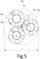
- the arch of the cable according to the invention is delimited by the strands and corresponds to the volume delimited by a theoretical circle, on the one hand, radially inside each strand and, on the other hand, tangent to each strand.
- the diameter of this theoretical circle is equal to the arch diameter Dv.
- the helix diameter De corresponds to the diameter of the theoretical circle passing through the centers of the strands of the layer in a plane perpendicular to the main axis of the cable.
- the pitch at which each strand is wound is the length travelled by this wire element, measured parallel to the axis of the cable in which it is located, at the end of which strand having this pitch makes a complete turn around said axis of the cable.
- each strand is delimited by the metal wires and corresponds to the volume delimited by a theoretical circle, on the one hand, radially inside each metal wire element and, on the other hand, tangent to each metal wire element.
- the diameter of this theoretical circle is equal to the arch diameter Dvt.
- the helix diameter Dh corresponds to the diameter of the theoretical circle passing through the centers of the wire elements of the layer in a plane perpendicular to the main axis of the cable.
- the pitch at which each metallic wire element is wound is the length travelled by this wire element, measured parallel to the axis of the cable in which it is located, at the end of which the wire element having this pitch makes a complete turn around said axis of the cable.
- all the metal wire elements have the same diameter Df.
- Each strand is manufactured in accordance with a process and using an installation described in the documents WO2016083265 And WO2016083267 .
- Such a method implementing a splitting step is to be distinguished from a conventional wiring method comprising a single assembly step in which the metal wire elements are wound in a helix, the assembly step being preceded by a step of individual preforming of each metal wire element in order in particular to increase the value of the structural elongation.
- Such methods and installations are described in the documents EP0548539 , EP1000194 , EP0622489 , WO2012055677 , JP2007092259 , WO2007128335 , JPH06346386 or even EP0143767 .
- the metal monofilaments are individually preformed.
- this step of individual preforming of the monofilaments metallic which requires a special installation, on the one hand, makes the process relatively unproductive compared to a process without an individual preforming step without however allowing high structural elongations to be achieved and, on the other hand, alters the metallic monofilaments thus preformed due to friction with the preforming tools.
- Such alteration creates incipient breaks on the surface of the metallic monofilaments and is therefore detrimental to the endurance of the metallic monofilaments, in particular to their endurance in compression.
- the absence or presence of such preforming marks can be observed under an electron microscope at the end of the manufacturing process, or more simply, by knowing the manufacturing process of the cable.
- each wire element of the cable is free of pre-forming marks.
- Such pre-forming marks include, in particular, flats.
- the pre-forming marks also include cracks extending in cutting planes substantially perpendicular to the main axis along which each wire element extends. Such cracks extend, in a cutting plane substantially perpendicular to the main axis, from a radially external surface of each wire element radially towards the inside of each wire element. As described above, such cracks are initiated by the mechanical pre-forming tools due to bending forces, i.e. perpendicular to the main axis of each wire element, which makes them very detrimental to endurance.
- the cable has a diameter D such that D ⁇ 6.00 mm and preferably D ⁇ 5.00 mm.
- the diameter or apparent diameter, noted D is measured by wedging the cable between two perfectly straight bars of length 200 mm and by measuring the spacing in which the cable is embedded using the comparator described below.
- the measurement protocol consists of three repetitions of a series of three measurements (carried out perpendicular to the axis of the cable and under zero tension)
- each wire element comprises a single metal monofilament.
- each metal wire element is advantageously made of a metal monofilament.
- the metal monofilament is directly coated with a layer of a metal coating comprising copper, zinc, tin, cobalt or an alloy of these metals, for example brass or bronze.
- each metal wire element is then made of the metal monofilament, for example steel, forming a core, directly coated with the layer of metal coating.
- each elementary metal monofilament is, as described above, preferably made of steel, and has a mechanical strength ranging from 1000 MPa to 5000 MPa.
- Such mechanical strengths correspond to the steel grades commonly encountered in the field of tires, namely, the grades NT (Normal Tensile), HT (High Tensile), ST (Super Tensile), SHT (Super High Tensile), UT (Ultra Tensile), UHT (Ultra High Tensile) and MT (Mega Tensile), the use of high mechanical strengths possibly allowing improved reinforcement of the matrix in which the cable is intended to be embedded and a lightening of the matrix thus reinforced.
- the layer is made up of N strands wound in a helix, N ranging from 2 to 6.
- the assembly process of the N strands is implemented by cabling.
- cabling we mean that the strands do not undergo torsion around their own axis, due to a synchronous rotation before and after the assembly point. This has the main advantage of increasing the ductility of the cables but also of achieving a greater breaking force than that of opencord strands alone.
- the separation step and the reassembly step are carried out so that M1'+M2' ⁇ M'.
- the step of providing the transient assembly comprises a step of assembly by twisting the M'>1 metallic wire elements wound in a helix around the transient core.
- the step of providing the transient assembly comprises a step of balancing the transient assembly.
- the balancing step being carried out on the transient assembly comprising the M'metal wire elements and the transient core, the balancing step is implicitly carried out upstream of the step of separation between the first and second split assemblies. It is avoided to have to manage the residual twist imposed during the step of assembling the transient assembly during the path of the different assemblies downstream of the assembly step, in particular in the guide means, for example the pulleys.
- the method comprises a step of balancing the final assembly downstream of the reassembly step.
- the method comprises a step of maintaining the rotation of the final assembly around its running direction.
- This rotation maintenance step is carried out downstream of the step of separating the transient assembly and upstream of the step of balancing the final assembly.
- the method is free of individual preforming steps for each of the wire elements.
- the latter are given a shape by preforming tools, for example rollers, these tools creating defects on the surface of the wire elements. These defects significantly reduce the endurance of the wire elements and therefore of the final assembly.
- the transitional core is a metal wire element.
- the transitional core is a metal monofilament.
- the diameter of the space between the metal wire elements and therefore the geometric characteristics of the final assembly are very precisely controlled, unlike a transitional core made of a textile material, for example polymeric, the compressibility of which can cause variations in the geometric characteristics of the final assembly.
- the transitional core is a textile filament element.
- a textile filament element comprises at least one multifilament textile strand or, alternatively, is made of a textile monofilament.
- the filaments textiles that can be used are chosen from polyesters, polyketones, aliphatic or aromatic polyamides and mixtures of textile filaments of these materials. This reduces the risks of breakage of the transitional core caused by friction of the metal wire elements on the transitional core as well as by the twists imposed on the transitional core.
- the invention also relates to a reinforced product comprising a polymer matrix and at least one extracted cable as defined above.
- the reinforced product comprises one or more cables according to the invention embedded in the polymer matrix, and in the case of several cables, the cables are arranged side by side in a main direction.
- the invention also relates to a tire comprising at least one extracted cable as defined above or a reinforced product as defined above.
- the tire comprises a carcass reinforcement anchored in two beads and surmounted radially by a crown reinforcement itself surmounted by a tread, the crown reinforcement being joined to said beads by two sidewalls and comprising at least one cable as defined above.
- the crown reinforcement comprises a protective reinforcement and a working reinforcement, the working reinforcement comprising at least one cable as defined above, the protective reinforcement being radially interposed between the tread and the working reinforcement.
- the cable is particularly intended for industrial vehicles selected from heavy vehicles such as "Heavy goods vehicles” - i.e., metro, bus, road transport vehicles (trucks, tractors, trailers), off-road vehicles -, agricultural or civil engineering vehicles, other transport or handling vehicles.
- heavy vehicles such as "Heavy goods vehicles” - i.e., metro, bus, road transport vehicles (trucks, tractors, trailers), off-road vehicles -, agricultural or civil engineering vehicles, other transport or handling vehicles.
- the tire is for civil engineering type vehicles.
- the tire has a dimension in which the diameter, in inches, of the seat of the rim on which the tire is intended to be mounted is greater than or equal to 30 inches.
- the invention also relates to a rubber article comprising an assembly according to the invention, or an impregnated assembly according to the invention.
- rubber article is meant any type of rubber article such as a ball, a non-pneumatic object such as a non-pneumatic tire, a conveyor belt or a caterpillar.
- the “median circumferential plane” M of the tire is the plane which is normal to the axis of rotation of the tire and which is located equidistant from the annular reinforcement structures of each bead.
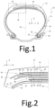
- the P tire is for heavy civil engineering type vehicles, for example “dumper” type.
- the P tire has a dimension of type 53/80R63.
- the tire P comprises a crown 12 reinforced by a crown reinforcement 14, two sidewalls 16 and two beads 18, each of these beads 18 being reinforced with an annular structure, here a bead wire 20.
- the crown reinforcement 14 is radially surmounted by a tread 22 and joined to the beads 18 by the sidewalls 16.
- a carcass reinforcement 24 is anchored in the two beads 18, and is here wound around the two bead wires 20 and comprises a turn-up 26 arranged towards the outside of the tire 20 which is here shown mounted on a rim 28.
- the carcass reinforcement 24 is radially surmounted by the crown reinforcement 14.
- the carcass reinforcement 24 comprises at least one carcass ply 30 reinforced by radial carcass cords (not shown).
- the carcass cords are arranged substantially parallel to each other and extend from one bead 18 to the other so as to form an angle of between 80° and 90° with the median circumferential plane M (plane perpendicular to the axis of rotation of the tire which is located midway between the two beads 18 and passes through the middle of the crown reinforcement 14).
- the tire P also comprises a sealing ply 32 made of an elastomer (commonly called inner rubber) which defines the radially internal face 34 of the tire P and which is intended to protect the carcass ply 30 from the diffusion of air coming from the space inside the tire P.
- a sealing ply 32 made of an elastomer (commonly called inner rubber) which defines the radially internal face 34 of the tire P and which is intended to protect the carcass ply 30 from the diffusion of air coming from the space inside the tire P.
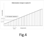
- the crown reinforcement 14 comprises, radially from the outside to the inside of the tire P, a protective reinforcement 36 arranged radially inside the tread 22, a working reinforcement 38 arranged radially inside the protective reinforcement 36 and an additional reinforcement 40 arranged radially inside the working reinforcement 38.
- the protective reinforcement 36 is thus radially intercalated between the tread 22 and the working reinforcement 38.
- the working reinforcement 38 is radially intercalated between the protective reinforcement 36 and the additional reinforcement 40.
- the protective frame 36 comprises first and second protective plies 42, 44 comprising protective metal cables, the first ply 42 being arranged radially inside the second ply 44.
- the protective metal cables make an angle at least equal to 10°, preferably ranging from 10° to 35° and preferentially from 15° to 30° with the circumferential direction Z of the tire.
- the working reinforcement 38 comprises first and second working plies 46, 48, the first ply 46 being arranged radially inside the second ply 48.
- Each ply 46, 48 comprises at least one cable 50.
- the working metal cables 50 are crossed from one working ply to the other and make an angle at most equal to 60°, preferably ranging from 15° to 40° with the circumferential direction Z of the tire.
- the additional frame 40 also called a limiter block, the function of which is to partially absorb the mechanical stresses of inflation, comprises, for example and in a manner known per se, additional metal reinforcement elements, for example as described in FR 2 419 181 Or FR 2 419 182 making an angle of at most 10°, preferably ranging from 5° to 10° with the circumferential direction Z of the tire P.
- the reinforced product R comprises at least one 50' cable, in this case several 50' cables, embedded in the polymer matrix Ma.
- the polymer matrix Ma the cables 50' are represented in a reference frame X, Y, Z in which the direction Y is the radial direction and the directions X and Z are the axial and circumferential directions.
- the reinforced product R comprises several cables 50 arranged side by side in the main direction X and extending parallel to each other within the reinforced product R and collectively embedded in the matrix polymeric Ma.
- the polymer matrix Ma is an elastomeric matrix based on an elastomeric composition.
- Each protective reinforcement element 43, 45 and each hoop reinforcement element 53, 55 is formed, after extraction of the tire 10, by an extracted cable 50' as described below.
- the cable 50 is obtained by embedding in a polymer matrix, in this case in a polymer matrix respectively forming each polymer matrix of each protective ply 42, 44 and of each hoop layer 52, 54 in which the protective reinforcement elements 43, 45 and hoop elements 53, 55 are respectively embedded.
- the 50 cable and the 50' extracted cable are single-layer metallic.
- the At value is determined by plotting a stress-strain curve of the 50 cable using ASTM D2969-04 of 2014.
- the cable 50 has a secant modulus E1 ranging from 3.0 to 10.0 GPa and preferably ranging from 3.5 to 8.5 GPa.
- E1 4.0 GPa
- Cable 50 has a tangent modulus E2 ranging from 50 to 180 GPa and preferably from 55 to 150 GPa.
- E2 73 GPa.
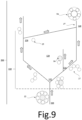
- the wire elements F1 and the transient core 16 are unwound from the supply means.
- the method comprises a step 100 of providing the transient assembly 22 comprising on the one hand a step of assembly by twisting the M' metallic wire elements F1 into a single layer of M' metallic wire elements F1 around the transient core 16 and on the other hand, a step of balancing the transient assembly 22 carried out using a finiister.
- the method comprises a step 110 of separating the transient assembly 22 between the first split assembly 25, the second split assembly 27 and the transient core 16 or one or more assemblies comprising the transient core 16, here the transient core 16.
- the step 110 of separating the transient assembly 22 between the first split assembly 25, the second split assembly 27 and the transient core 16 comprises a step 120 of separating the transient assembly 22 between the precursor assembly, the second split assembly 27 and finally the transient core 16.
- the separation step 120 of the assembly transient between the precursor assembly and the split assembly comprises a step 124 of separating the split assembly between the second split assembly 27 and the transient core 16.
- the separation step 124 comprises a step of splitting the split assembly into the second split assembly 27, the transient core 16 and the complementary assembly.
- the step 110 of separating the transient assembly between the first split assembly 25, the second split assembly 27 and the transient core 16 comprises a step 130 of separating the precursor assembly between the first split assembly 25 and the complementary assembly.
- the method comprises a step 140 of reassembling the first split assembly 25 with the second split assembly 27 to form the strand 54.
- the supply step 100, the separation step 110 and the reassembly step 140 are carried out so that all the M' metallic wire elements F1 have the same diameter Df, are wound in a helix according to the same pitch P and have the same helix curvature radius Rf described previously.
- the separation step 110 and the reassembly step 140 are carried out so that M1'+M2' ⁇ M'.
- a final balancing step is carried out.
- strand 54 is stored on a storage reel. N strands 54 are manufactured in the same way.
- the method comprises a step of recycling the transient core 16.
- the transient core 16 is recovered downstream of the separation step 110, here downstream of the separation step 124, and the transient core 16 recovered previously is introduced upstream of the assembly step.
- This recycling step is continuous.
- Tables 1, 2 and 3 below summarize the characteristics for the different cables 50, 50', 60, 60', 51, 52, 53, 53', 54 according to the invention and for the state-of-the-art cables EDT1, EDT1', EDT2 and EDT2'.
- the stress-strain curves of the cables were plotted by applying the ASTM D2969-04 standard of 2014 and the total elongation and the breaking energy indicator were determined for the different cables 50, 50', 60, 60', 51, 52, 53, 53', 54 according to the invention and for the state-of-the-art cables EDT1, EDT1', EDT2 and EDT2'.
- Tables 1, 2 and 3 show that the cables 50, 50', 60, 60', 51, 52, 53, 53', 54 according to the invention have both an improved breaking energy indicator and have better deformability compared to the state-of-the-art cables EDT1, EDT1', EDT2 and EDT2'.
- the cables according to the invention make it possible to solve the problems mentioned in the preamble.
Landscapes
- Ropes Or Cables (AREA)
- Tires In General (AREA)
Applications Claiming Priority (2)
| Application Number | Priority Date | Filing Date | Title |
|---|---|---|---|
| FR2000097 | 2020-01-07 | ||
| PCT/FR2020/052526 WO2021140287A1 (fr) | 2020-01-07 | 2020-12-18 | Câble multi-torons à une couche à énergie à rupture améliorée et à allongement total amélioré |
Publications (2)
| Publication Number | Publication Date |
|---|---|
| EP4087970A1 EP4087970A1 (fr) | 2022-11-16 |
| EP4087970B1 true EP4087970B1 (fr) | 2024-08-28 |
Family
ID=70154623
Family Applications (1)
| Application Number | Title | Priority Date | Filing Date |
|---|---|---|---|
| EP20845790.3A Active EP4087970B1 (fr) | 2020-01-07 | 2020-12-18 | Câble multi-torons à une couche à énergie à rupture améliorée et à allongement total amélioré |
Country Status (6)
| Country | Link |
|---|---|
| US (1) | US12258707B2 (cg-RX-API-DMAC10.html) |
| EP (1) | EP4087970B1 (cg-RX-API-DMAC10.html) |
| JP (1) | JP7737379B2 (cg-RX-API-DMAC10.html) |
| KR (1) | KR102885566B1 (cg-RX-API-DMAC10.html) |
| CN (1) | CN114929963B (cg-RX-API-DMAC10.html) |
| WO (1) | WO2021140287A1 (cg-RX-API-DMAC10.html) |
Families Citing this family (9)
| Publication number | Priority date | Publication date | Assignee | Title |
|---|---|---|---|---|
| FR3099191A1 (fr) | 2019-07-25 | 2021-01-29 | Compagnie Generale Des Etablissements Michelin | Câble ouvert renforçant à haute compressibilité |
| FR3099192A1 (fr) | 2019-07-25 | 2021-01-29 | Compagnie Generale Des Etablissements Michelin | Procédé de fractionnement et de réassemblage d’un assemblage à deux couches |
| FR3099189A1 (fr) | 2019-07-25 | 2021-01-29 | Compagnie Generale Des Etablissements Michelin | Procédé de fractionnement et de réassemblage |
| FR3129411B1 (fr) * | 2021-11-25 | 2025-04-18 | Michelin & Cie | Produit renforcé à géométrie de câble fixé présentant un comportement bimodule très fort pour la déformabilité du câble en usage hors la route |
| FR3129409B1 (fr) | 2021-11-25 | 2023-10-20 | Michelin & Cie | Produit renforcé à géométrie de câble fixé présentant un comportement bimodule à rigidité adaptée |
| FR3129319B1 (fr) | 2021-11-25 | 2024-02-09 | Michelin & Cie | Produit renforcé à géométrie de câble fixé présentant un comportement bimodule intermédiaire |
| FR3136787B1 (fr) * | 2022-06-20 | 2024-05-10 | Michelin & Cie | Câble multi-torons à une couche de multi-torons |
| CN116955894B (zh) * | 2023-09-20 | 2024-01-09 | 肇庆星诺奇传动科技有限公司 | 一种在线自适应螺纹长度信息校准方法及系统 |
| FR3156458B1 (fr) * | 2023-12-12 | 2025-10-24 | Michelin & Cie | Câble à une couche à énergie à rupture améliorée et à allongement total amélioré |
Family Cites Families (33)
| Publication number | Priority date | Publication date | Assignee | Title |
|---|---|---|---|---|
| US3683024A (en) | 1968-06-18 | 1972-08-08 | Texaco Inc | O-polyalkoxylated high molecular weight-n-alkanone and n-alkanal oximes |
| FR2419182A1 (fr) | 1978-03-10 | 1979-10-05 | Michelin & Cie | Pneumatique a carcasse radiale, notamment pour engins de genie civil |
| FR2419181A1 (fr) | 1978-03-10 | 1979-10-05 | Michelin & Cie | Perfectionnements aux pneumatiques a carcasse radiale |
| JPS6059188A (ja) | 1983-09-02 | 1985-04-05 | ブリヂストン・ベカルト・スチ−ル・コ−ド株式会社 | ゴム物品補強用スチ−ルコ−ド |
| CA1218921A (en) * | 1983-12-21 | 1987-03-10 | Tadao Kanuma | Tire-reinforcing dip cord and process for preparation thereof |
| JPH02104785A (ja) * | 1988-10-14 | 1990-04-17 | Kokoku Kousensaku Kk | タイヤ用複撚スチールコードおよびタイヤ |
| US5048280A (en) | 1988-12-27 | 1991-09-17 | Sumimoto Electric Industries, Ltd. | Steel composite cord |
| JPH0768673B2 (ja) | 1991-12-27 | 1995-07-26 | トクセン工業株式会社 | ゴム製品補強用スチールコード |
| DE4314172C1 (de) | 1993-04-29 | 1994-09-15 | Witels App Masch Albert Gmbh | Vorformkopf für Seile und Kabelarmierungen |
| JPH06346386A (ja) | 1993-06-02 | 1994-12-20 | Sumitomo Electric Ind Ltd | ゴム物品補強用金属コード |
| JP2896976B2 (ja) * | 1995-06-27 | 1999-05-31 | 東京製綱株式会社 | 建設車両用スチールコード及び建設車両用タイヤ |
| JP3563162B2 (ja) * | 1995-07-19 | 2004-09-08 | 株式会社クラレ | 熱可塑性メタクリル樹脂組成物 |
| EP1000194B1 (en) | 1997-07-29 | 2002-09-04 | Bekaert Naamloze Vennootschap | Steel cord for protection plies of pneumatic tyres |
| JPH11286205A (ja) * | 1998-04-02 | 1999-10-19 | Bridgestone Corp | 空気入りタイヤ |
| FR2841573A1 (fr) * | 2002-06-26 | 2004-01-02 | Michelin Soc Tech | Cables hybrides a couches utilisables pour renforcer des pneumatiques |
| JP4646770B2 (ja) | 2005-09-30 | 2011-03-09 | 金井 宏彰 | スチールコードおよび自動車用タイヤ |
| FR2897076B1 (fr) * | 2006-02-09 | 2008-04-18 | Michelin Soc Tech | Cable composite elastique pour pneumatique. |
| WO2007128335A1 (en) | 2006-05-10 | 2007-11-15 | Pirelli Tyre S.P.A. | Metal cord and process for manufacturing a metal cord |
| JP4659099B2 (ja) * | 2009-02-16 | 2011-03-30 | 住友ゴム工業株式会社 | 自動二輪車用タイヤ、及びその製造方法 |
| FR2947577B1 (fr) * | 2009-07-03 | 2013-02-22 | Michelin Soc Tech | Cable metallique a trois couches gomme in situ de construction 3+m+n |
| FR2947574B1 (fr) * | 2009-07-03 | 2012-11-09 | Michelin Soc Tech | Cable multitorons dont les torons elementaires sont des cables a deux couches gommes in situ. |
| US8375692B2 (en) * | 2010-07-16 | 2013-02-19 | E I Du Pont De Nemours And Company | Composite cord having a metal core and method of making |
| WO2012055677A2 (en) | 2010-10-27 | 2012-05-03 | Nv Bekaert Sa | Open steel cord |
| FR2990962B1 (fr) * | 2012-05-25 | 2014-06-27 | Michelin & Cie | Procede de fabrication d'un cable metallique multi-torons a deux couches. |
| JP5987574B2 (ja) * | 2012-09-12 | 2016-09-07 | 横浜ゴム株式会社 | スチールコード及びそれを用いた建設車両用空気入りラジアルタイヤ |
| HUE053814T2 (hu) * | 2013-08-01 | 2021-07-28 | Bekaert Sa Nv | Nagy fajlagos nyúlású acélkord és ilyen kordot tartalmazó légabroncs |
| FR3028873B1 (fr) | 2014-11-25 | 2016-12-23 | Michelin & Cie | Installation de fractionnement |
| FR3028872B1 (fr) * | 2014-11-25 | 2017-05-19 | Michelin & Cie | Procede de fractionnement |
| FR3032978B1 (fr) | 2015-02-19 | 2017-10-27 | Michelin & Cie | Cable multitorons de structure 1xn pour armature de protection de pneumatique |
| EP3286018B1 (en) | 2015-04-24 | 2021-03-10 | Pirelli Tyre S.p.A. | High-performance tyre |
| FR3017885A1 (fr) * | 2015-06-16 | 2015-08-28 | Michelin & Cie | Cable metallique multi-torons |
| KR102646060B1 (ko) | 2018-07-25 | 2024-03-13 | 꽁빠니 제네날 드 에따블리세망 미쉘린 | 고 압축성 개방 코드 |
| FR3099191A1 (fr) | 2019-07-25 | 2021-01-29 | Compagnie Generale Des Etablissements Michelin | Câble ouvert renforçant à haute compressibilité |
-
2020
- 2020-12-18 CN CN202080092137.8A patent/CN114929963B/zh active Active
- 2020-12-18 US US17/791,272 patent/US12258707B2/en active Active
- 2020-12-18 WO PCT/FR2020/052526 patent/WO2021140287A1/fr not_active Ceased
- 2020-12-18 EP EP20845790.3A patent/EP4087970B1/fr active Active
- 2020-12-18 JP JP2022541819A patent/JP7737379B2/ja active Active
- 2020-12-18 KR KR1020227026903A patent/KR102885566B1/ko active Active
Also Published As
| Publication number | Publication date |
|---|---|
| US20230349097A1 (en) | 2023-11-02 |
| WO2021140287A1 (fr) | 2021-07-15 |
| CN114929963A (zh) | 2022-08-19 |
| JP2023509076A (ja) | 2023-03-06 |
| US12258707B2 (en) | 2025-03-25 |
| EP4087970A1 (fr) | 2022-11-16 |
| KR102885566B1 (ko) | 2025-11-13 |
| JP7737379B2 (ja) | 2025-09-10 |
| KR20220116335A (ko) | 2022-08-22 |
| CN114929963B (zh) | 2023-07-21 |
Similar Documents
| Publication | Publication Date | Title |
|---|---|---|
| WO2021140287A1 (fr) | Câble multi-torons à une couche à énergie à rupture améliorée et à allongement total amélioré | |
| EP4061996B1 (fr) | Câble multi-torons à deux couches à énergie de rupture surfacique améliorée | |
| EP4172406B1 (fr) | Câble multi-torons à deux couches à endurance sous flexion améliorée | |
| EP4172405B1 (fr) | Câble multi-torons à deux couches à endurance sous flexion améliorée | |
| EP4172407B1 (fr) | Câble multi-torons à deux couches à endurance sous flexion améliorée | |
| EP4172408B1 (fr) | Câble multi-torons à deux couches à endurance sous flexion améliorée | |
| EP4087971B1 (fr) | Câble multi-torons à deux couches à énergie à rupture améliorée et à module tangent bas | |
| EP4334523B1 (fr) | Câble multi-torons à deux couches à énergie de rupture surfacique améliorée | |
| EP4334141B1 (fr) | Câble multi-torons à deux couches à énergie de rupture surfacique améliorée | |
| WO2022096799A1 (fr) | Câble multi-torons à deux couches avec couche interne gainée à pénétrabilité améliorée | |
| EP4334524B1 (fr) | Câble multi-torons à deux couches à énergie de rupture surfacique améliorée | |
| EP4540455B1 (fr) | Câble multi-torons à deux couches de multi-torons | |
| EP4540456B1 (fr) | Câble multi-torons à deux couches de multi-torons | |
| EP4540458B1 (fr) | Câble multi-torons à une couche de multi-torons | |
| WO2025124998A1 (fr) | Câble à une couche à énergie à rupture améliorée et à allongement total amélioré | |
| FR3122674A1 (fr) | Câble multi-torons à deux couches à énergie de rupture surfacique améliorée | |
| FR3122675A1 (fr) | Câble multi-torons à deux couches à énergie de rupture surfacique améliorée | |
| FR3122673A1 (fr) | Câble multi-torons à deux couches à énergie de rupture surfacique améliorée | |
| FR3122678A1 (fr) | Câble multi-torons à deux couches à énergie de rupture surfacique améliorée | |
| FR3130858A1 (fr) | Câble multi-torons à deux couches à endurance sous flexion améliorée | |
| FR3156457A1 (fr) | Câble extrait à une couche à répartition optimisée des fils | |
| WO2021094675A1 (fr) | Câble multi-torons à deux couches avec couche interne gainée à pénétrabilité améliorée |
Legal Events
| Date | Code | Title | Description |
|---|---|---|---|
| STAA | Information on the status of an ep patent application or granted ep patent |
Free format text: STATUS: UNKNOWN |
|
| STAA | Information on the status of an ep patent application or granted ep patent |
Free format text: STATUS: THE INTERNATIONAL PUBLICATION HAS BEEN MADE |
|
| PUAI | Public reference made under article 153(3) epc to a published international application that has entered the european phase |
Free format text: ORIGINAL CODE: 0009012 |
|
| STAA | Information on the status of an ep patent application or granted ep patent |
Free format text: STATUS: REQUEST FOR EXAMINATION WAS MADE |
|
| 17P | Request for examination filed |
Effective date: 20220808 |
|
| AK | Designated contracting states |
Kind code of ref document: A1 Designated state(s): AL AT BE BG CH CY CZ DE DK EE ES FI FR GB GR HR HU IE IS IT LI LT LU LV MC MK MT NL NO PL PT RO RS SE SI SK SM TR |
|
| DAV | Request for validation of the european patent (deleted) | ||
| DAX | Request for extension of the european patent (deleted) | ||
| STAA | Information on the status of an ep patent application or granted ep patent |
Free format text: STATUS: EXAMINATION IS IN PROGRESS |
|
| 17Q | First examination report despatched |
Effective date: 20230808 |
|
| GRAP | Despatch of communication of intention to grant a patent |
Free format text: ORIGINAL CODE: EPIDOSNIGR1 |
|
| STAA | Information on the status of an ep patent application or granted ep patent |
Free format text: STATUS: GRANT OF PATENT IS INTENDED |
|
| INTG | Intention to grant announced |
Effective date: 20240503 |
|
| GRAS | Grant fee paid |
Free format text: ORIGINAL CODE: EPIDOSNIGR3 |
|
| GRAA | (expected) grant |
Free format text: ORIGINAL CODE: 0009210 |
|
| STAA | Information on the status of an ep patent application or granted ep patent |
Free format text: STATUS: THE PATENT HAS BEEN GRANTED |
|
| AK | Designated contracting states |
Kind code of ref document: B1 Designated state(s): AL AT BE BG CH CY CZ DE DK EE ES FI FR GB GR HR HU IE IS IT LI LT LU LV MC MK MT NL NO PL PT RO RS SE SI SK SM TR |
|
| REG | Reference to a national code |
Ref country code: CH Ref legal event code: EP |
|
| REG | Reference to a national code |
Ref country code: DE Ref legal event code: R096 Ref document number: 602020036836 Country of ref document: DE |
|
| REG | Reference to a national code |
Ref country code: IE Ref legal event code: FG4D Free format text: LANGUAGE OF EP DOCUMENT: FRENCH |
|
| REG | Reference to a national code |
Ref country code: LT Ref legal event code: MG9D |
|
| PG25 | Lapsed in a contracting state [announced via postgrant information from national office to epo] |
Ref country code: NO Free format text: LAPSE BECAUSE OF FAILURE TO SUBMIT A TRANSLATION OF THE DESCRIPTION OR TO PAY THE FEE WITHIN THE PRESCRIBED TIME-LIMIT Effective date: 20241128 |
|
| REG | Reference to a national code |
Ref country code: AT Ref legal event code: MK05 Ref document number: 1718064 Country of ref document: AT Kind code of ref document: T Effective date: 20240828 |
|
| PG25 | Lapsed in a contracting state [announced via postgrant information from national office to epo] |
Ref country code: PT Free format text: LAPSE BECAUSE OF FAILURE TO SUBMIT A TRANSLATION OF THE DESCRIPTION OR TO PAY THE FEE WITHIN THE PRESCRIBED TIME-LIMIT Effective date: 20241230 Ref country code: NL Free format text: LAPSE BECAUSE OF FAILURE TO SUBMIT A TRANSLATION OF THE DESCRIPTION OR TO PAY THE FEE WITHIN THE PRESCRIBED TIME-LIMIT Effective date: 20240828 Ref country code: GR Free format text: LAPSE BECAUSE OF FAILURE TO SUBMIT A TRANSLATION OF THE DESCRIPTION OR TO PAY THE FEE WITHIN THE PRESCRIBED TIME-LIMIT Effective date: 20241129 Ref country code: FI Free format text: LAPSE BECAUSE OF FAILURE TO SUBMIT A TRANSLATION OF THE DESCRIPTION OR TO PAY THE FEE WITHIN THE PRESCRIBED TIME-LIMIT Effective date: 20240828 Ref country code: PL Free format text: LAPSE BECAUSE OF FAILURE TO SUBMIT A TRANSLATION OF THE DESCRIPTION OR TO PAY THE FEE WITHIN THE PRESCRIBED TIME-LIMIT Effective date: 20240828 |
|
| PG25 | Lapsed in a contracting state [announced via postgrant information from national office to epo] |
Ref country code: BG Free format text: LAPSE BECAUSE OF FAILURE TO SUBMIT A TRANSLATION OF THE DESCRIPTION OR TO PAY THE FEE WITHIN THE PRESCRIBED TIME-LIMIT Effective date: 20240828 |
|
| PG25 | Lapsed in a contracting state [announced via postgrant information from national office to epo] |
Ref country code: LV Free format text: LAPSE BECAUSE OF FAILURE TO SUBMIT A TRANSLATION OF THE DESCRIPTION OR TO PAY THE FEE WITHIN THE PRESCRIBED TIME-LIMIT Effective date: 20240828 |
|
| REG | Reference to a national code |
Ref country code: NL Ref legal event code: MP Effective date: 20240828 |
|
| PG25 | Lapsed in a contracting state [announced via postgrant information from national office to epo] |
Ref country code: AT Free format text: LAPSE BECAUSE OF FAILURE TO SUBMIT A TRANSLATION OF THE DESCRIPTION OR TO PAY THE FEE WITHIN THE PRESCRIBED TIME-LIMIT Effective date: 20240828 Ref country code: IS Free format text: LAPSE BECAUSE OF FAILURE TO SUBMIT A TRANSLATION OF THE DESCRIPTION OR TO PAY THE FEE WITHIN THE PRESCRIBED TIME-LIMIT Effective date: 20241228 |
|
| PG25 | Lapsed in a contracting state [announced via postgrant information from national office to epo] |
Ref country code: HR Free format text: LAPSE BECAUSE OF FAILURE TO SUBMIT A TRANSLATION OF THE DESCRIPTION OR TO PAY THE FEE WITHIN THE PRESCRIBED TIME-LIMIT Effective date: 20240828 |
|
| PG25 | Lapsed in a contracting state [announced via postgrant information from national office to epo] |
Ref country code: RS Free format text: LAPSE BECAUSE OF FAILURE TO SUBMIT A TRANSLATION OF THE DESCRIPTION OR TO PAY THE FEE WITHIN THE PRESCRIBED TIME-LIMIT Effective date: 20241128 Ref country code: ES Free format text: LAPSE BECAUSE OF FAILURE TO SUBMIT A TRANSLATION OF THE DESCRIPTION OR TO PAY THE FEE WITHIN THE PRESCRIBED TIME-LIMIT Effective date: 20240828 |
|
| PG25 | Lapsed in a contracting state [announced via postgrant information from national office to epo] |
Ref country code: RS Free format text: LAPSE BECAUSE OF FAILURE TO SUBMIT A TRANSLATION OF THE DESCRIPTION OR TO PAY THE FEE WITHIN THE PRESCRIBED TIME-LIMIT Effective date: 20241128 Ref country code: PT Free format text: LAPSE BECAUSE OF FAILURE TO SUBMIT A TRANSLATION OF THE DESCRIPTION OR TO PAY THE FEE WITHIN THE PRESCRIBED TIME-LIMIT Effective date: 20241230 Ref country code: PL Free format text: LAPSE BECAUSE OF FAILURE TO SUBMIT A TRANSLATION OF THE DESCRIPTION OR TO PAY THE FEE WITHIN THE PRESCRIBED TIME-LIMIT Effective date: 20240828 Ref country code: NO Free format text: LAPSE BECAUSE OF FAILURE TO SUBMIT A TRANSLATION OF THE DESCRIPTION OR TO PAY THE FEE WITHIN THE PRESCRIBED TIME-LIMIT Effective date: 20241128 Ref country code: NL Free format text: LAPSE BECAUSE OF FAILURE TO SUBMIT A TRANSLATION OF THE DESCRIPTION OR TO PAY THE FEE WITHIN THE PRESCRIBED TIME-LIMIT Effective date: 20240828 Ref country code: LV Free format text: LAPSE BECAUSE OF FAILURE TO SUBMIT A TRANSLATION OF THE DESCRIPTION OR TO PAY THE FEE WITHIN THE PRESCRIBED TIME-LIMIT Effective date: 20240828 Ref country code: IS Free format text: LAPSE BECAUSE OF FAILURE TO SUBMIT A TRANSLATION OF THE DESCRIPTION OR TO PAY THE FEE WITHIN THE PRESCRIBED TIME-LIMIT Effective date: 20241228 Ref country code: HR Free format text: LAPSE BECAUSE OF FAILURE TO SUBMIT A TRANSLATION OF THE DESCRIPTION OR TO PAY THE FEE WITHIN THE PRESCRIBED TIME-LIMIT Effective date: 20240828 Ref country code: GR Free format text: LAPSE BECAUSE OF FAILURE TO SUBMIT A TRANSLATION OF THE DESCRIPTION OR TO PAY THE FEE WITHIN THE PRESCRIBED TIME-LIMIT Effective date: 20241129 Ref country code: FI Free format text: LAPSE BECAUSE OF FAILURE TO SUBMIT A TRANSLATION OF THE DESCRIPTION OR TO PAY THE FEE WITHIN THE PRESCRIBED TIME-LIMIT Effective date: 20240828 Ref country code: ES Free format text: LAPSE BECAUSE OF FAILURE TO SUBMIT A TRANSLATION OF THE DESCRIPTION OR TO PAY THE FEE WITHIN THE PRESCRIBED TIME-LIMIT Effective date: 20240828 Ref country code: BG Free format text: LAPSE BECAUSE OF FAILURE TO SUBMIT A TRANSLATION OF THE DESCRIPTION OR TO PAY THE FEE WITHIN THE PRESCRIBED TIME-LIMIT Effective date: 20240828 Ref country code: AT Free format text: LAPSE BECAUSE OF FAILURE TO SUBMIT A TRANSLATION OF THE DESCRIPTION OR TO PAY THE FEE WITHIN THE PRESCRIBED TIME-LIMIT Effective date: 20240828 |
|
| PG25 | Lapsed in a contracting state [announced via postgrant information from national office to epo] |
Ref country code: SM Free format text: LAPSE BECAUSE OF FAILURE TO SUBMIT A TRANSLATION OF THE DESCRIPTION OR TO PAY THE FEE WITHIN THE PRESCRIBED TIME-LIMIT Effective date: 20240828 Ref country code: DK Free format text: LAPSE BECAUSE OF FAILURE TO SUBMIT A TRANSLATION OF THE DESCRIPTION OR TO PAY THE FEE WITHIN THE PRESCRIBED TIME-LIMIT Effective date: 20240828 Ref country code: RO Free format text: LAPSE BECAUSE OF FAILURE TO SUBMIT A TRANSLATION OF THE DESCRIPTION OR TO PAY THE FEE WITHIN THE PRESCRIBED TIME-LIMIT Effective date: 20240828 |
|
| PG25 | Lapsed in a contracting state [announced via postgrant information from national office to epo] |
Ref country code: EE Free format text: LAPSE BECAUSE OF FAILURE TO SUBMIT A TRANSLATION OF THE DESCRIPTION OR TO PAY THE FEE WITHIN THE PRESCRIBED TIME-LIMIT Effective date: 20240828 |
|
| PG25 | Lapsed in a contracting state [announced via postgrant information from national office to epo] |
Ref country code: CZ Free format text: LAPSE BECAUSE OF FAILURE TO SUBMIT A TRANSLATION OF THE DESCRIPTION OR TO PAY THE FEE WITHIN THE PRESCRIBED TIME-LIMIT Effective date: 20240828 |
|
| PG25 | Lapsed in a contracting state [announced via postgrant information from national office to epo] |
Ref country code: SK Free format text: LAPSE BECAUSE OF FAILURE TO SUBMIT A TRANSLATION OF THE DESCRIPTION OR TO PAY THE FEE WITHIN THE PRESCRIBED TIME-LIMIT Effective date: 20240828 Ref country code: IT Free format text: LAPSE BECAUSE OF FAILURE TO SUBMIT A TRANSLATION OF THE DESCRIPTION OR TO PAY THE FEE WITHIN THE PRESCRIBED TIME-LIMIT Effective date: 20240828 |
|
| REG | Reference to a national code |
Ref country code: DE Ref legal event code: R097 Ref document number: 602020036836 Country of ref document: DE |
|
| PLBE | No opposition filed within time limit |
Free format text: ORIGINAL CODE: 0009261 |
|
| STAA | Information on the status of an ep patent application or granted ep patent |
Free format text: STATUS: NO OPPOSITION FILED WITHIN TIME LIMIT |
|
| PG25 | Lapsed in a contracting state [announced via postgrant information from national office to epo] |
Ref country code: MC Free format text: LAPSE BECAUSE OF FAILURE TO SUBMIT A TRANSLATION OF THE DESCRIPTION OR TO PAY THE FEE WITHIN THE PRESCRIBED TIME-LIMIT Effective date: 20240828 |
|
| REG | Reference to a national code |
Ref country code: CH Ref legal event code: PL |
|
| 26N | No opposition filed |
Effective date: 20250530 |
|
| PG25 | Lapsed in a contracting state [announced via postgrant information from national office to epo] |
Ref country code: LU Free format text: LAPSE BECAUSE OF NON-PAYMENT OF DUE FEES Effective date: 20241218 |
|
| GBPC | Gb: european patent ceased through non-payment of renewal fee |
Effective date: 20241218 |
|
| PG25 | Lapsed in a contracting state [announced via postgrant information from national office to epo] |
Ref country code: SE Free format text: LAPSE BECAUSE OF FAILURE TO SUBMIT A TRANSLATION OF THE DESCRIPTION OR TO PAY THE FEE WITHIN THE PRESCRIBED TIME-LIMIT Effective date: 20240828 |
|
| REG | Reference to a national code |
Ref country code: BE Ref legal event code: MM Effective date: 20241231 |
|
| PG25 | Lapsed in a contracting state [announced via postgrant information from national office to epo] |
Ref country code: BE Free format text: LAPSE BECAUSE OF NON-PAYMENT OF DUE FEES Effective date: 20241231 Ref country code: GB Free format text: LAPSE BECAUSE OF NON-PAYMENT OF DUE FEES Effective date: 20241218 |
|
| PG25 | Lapsed in a contracting state [announced via postgrant information from national office to epo] |
Ref country code: CH Free format text: LAPSE BECAUSE OF NON-PAYMENT OF DUE FEES Effective date: 20241231 |
|
| PG25 | Lapsed in a contracting state [announced via postgrant information from national office to epo] |
Ref country code: IE Free format text: LAPSE BECAUSE OF NON-PAYMENT OF DUE FEES Effective date: 20241218 |
|
| PGFP | Annual fee paid to national office [announced via postgrant information from national office to epo] |
Ref country code: DE Payment date: 20251211 Year of fee payment: 6 |
|
| PGFP | Annual fee paid to national office [announced via postgrant information from national office to epo] |
Ref country code: FR Payment date: 20251229 Year of fee payment: 6 |
|
| PG25 | Lapsed in a contracting state [announced via postgrant information from national office to epo] |
Ref country code: CY Free format text: LAPSE BECAUSE OF FAILURE TO SUBMIT A TRANSLATION OF THE DESCRIPTION OR TO PAY THE FEE WITHIN THE PRESCRIBED TIME-LIMIT Effective date: 20240828 |
|
| PG25 | Lapsed in a contracting state [announced via postgrant information from national office to epo] |
Ref country code: TR Free format text: LAPSE BECAUSE OF FAILURE TO SUBMIT A TRANSLATION OF THE DESCRIPTION OR TO PAY THE FEE WITHIN THE PRESCRIBED TIME-LIMIT Effective date: 20240828 |
|
| PG25 | Lapsed in a contracting state [announced via postgrant information from national office to epo] |
Ref country code: HU Free format text: LAPSE BECAUSE OF FAILURE TO SUBMIT A TRANSLATION OF THE DESCRIPTION OR TO PAY THE FEE WITHIN THE PRESCRIBED TIME-LIMIT; INVALID AB INITIO Effective date: 20201218 |
|
| PG25 | Lapsed in a contracting state [announced via postgrant information from national office to epo] |
Ref country code: SI Free format text: LAPSE BECAUSE OF FAILURE TO SUBMIT A TRANSLATION OF THE DESCRIPTION OR TO PAY THE FEE WITHIN THE PRESCRIBED TIME-LIMIT Effective date: 20240828 |
|
| PG25 | Lapsed in a contracting state [announced via postgrant information from national office to epo] |
Ref country code: LT Free format text: LAPSE BECAUSE OF FAILURE TO SUBMIT A TRANSLATION OF THE DESCRIPTION OR TO PAY THE FEE WITHIN THE PRESCRIBED TIME-LIMIT Effective date: 20240828 |