EP4087103B1 - Linearantrieb - Google Patents
Linearantrieb Download PDFInfo
- Publication number
- EP4087103B1 EP4087103B1 EP21171873.9A EP21171873A EP4087103B1 EP 4087103 B1 EP4087103 B1 EP 4087103B1 EP 21171873 A EP21171873 A EP 21171873A EP 4087103 B1 EP4087103 B1 EP 4087103B1
- Authority
- EP
- European Patent Office
- Prior art keywords
- magnetic wheel
- linear drive
- secondary part
- drive system
- magnets
- Prior art date
- Legal status (The legal status is an assumption and is not a legal conclusion. Google has not performed a legal analysis and makes no representation as to the accuracy of the status listed.)
- Active
Links
Images

Classifications
-
- H—ELECTRICITY
- H02—GENERATION; CONVERSION OR DISTRIBUTION OF ELECTRIC POWER
- H02K—DYNAMO-ELECTRIC MACHINES
- H02K49/00—Dynamo-electric clutches; Dynamo-electric brakes
- H02K49/02—Dynamo-electric clutches; Dynamo-electric brakes of the asynchronous induction type
- H02K49/04—Dynamo-electric clutches; Dynamo-electric brakes of the asynchronous induction type of the eddy-current hysteresis type
- H02K49/046—Dynamo-electric clutches; Dynamo-electric brakes of the asynchronous induction type of the eddy-current hysteresis type with an axial airgap
-
- H—ELECTRICITY
- H02—GENERATION; CONVERSION OR DISTRIBUTION OF ELECTRIC POWER
- H02K—DYNAMO-ELECTRIC MACHINES
- H02K41/00—Propulsion systems in which a rigid body is moved along a path due to dynamo-electric interaction between the body and a magnetic field travelling along the path
- H02K41/02—Linear motors; Sectional motors
- H02K41/025—Asynchronous motors
-
- B—PERFORMING OPERATIONS; TRANSPORTING
- B60—VEHICLES IN GENERAL
- B60L—PROPULSION OF ELECTRICALLY-PROPELLED VEHICLES; SUPPLYING ELECTRIC POWER FOR AUXILIARY EQUIPMENT OF ELECTRICALLY-PROPELLED VEHICLES; ELECTRODYNAMIC BRAKE SYSTEMS FOR VEHICLES IN GENERAL; MAGNETIC SUSPENSION OR LEVITATION FOR VEHICLES; MONITORING OPERATING VARIABLES OF ELECTRICALLY-PROPELLED VEHICLES; ELECTRIC SAFETY DEVICES FOR ELECTRICALLY-PROPELLED VEHICLES
- B60L13/00—Electric propulsion for monorail vehicles, suspension vehicles or rack railways; Magnetic suspension or levitation for vehicles
- B60L13/03—Electric propulsion by linear motors
-
- B—PERFORMING OPERATIONS; TRANSPORTING
- B60—VEHICLES IN GENERAL
- B60L—PROPULSION OF ELECTRICALLY-PROPELLED VEHICLES; SUPPLYING ELECTRIC POWER FOR AUXILIARY EQUIPMENT OF ELECTRICALLY-PROPELLED VEHICLES; ELECTRODYNAMIC BRAKE SYSTEMS FOR VEHICLES IN GENERAL; MAGNETIC SUSPENSION OR LEVITATION FOR VEHICLES; MONITORING OPERATING VARIABLES OF ELECTRICALLY-PROPELLED VEHICLES; ELECTRIC SAFETY DEVICES FOR ELECTRICALLY-PROPELLED VEHICLES
- B60L2200/00—Type of vehicles
- B60L2200/26—Rail vehicles
Definitions
- the present invention falls within the technical field of electric drives for track-guided land transport means or rail vehicles; it relates in the present case to a linear drive for operating a vehicle along a section of a route according to the preamble of claim 1.
- a linear drive or linear motor is an electric drive machine in which, unlike conventional rotating machines, the driven objects are not set in a rotating motion, but are moved along a straight or curved path. Consequently, linear drives are not referred to as a rotational movement, but as a translational movement.
- roller coaster trains are typically catapulted into a tangle of steel tubes by an electromagnetic linear drive every two minutes, with such a roller coaster train, which weighs several tons, receiving its initial energy on a catapult track around 50 meters long by means of around 100 linear induction motors - also known as LIMs - installed in pairs.
- LIMs linear induction motors
- Such a LIM was and is a logical further development of a contactless acceleration system with the aim of largely mechanically being maintenance-free.
- LIMs are also used in mechanical drives for door systems - such as in supermarkets, for example - or in passenger conveyor belts and baggage conveyors at airports.
- the linear induction motor is based on the principle of the AC motor. The only and most noticeable difference is that it generates a translational movement instead of a rotary movement.
- the stator coils which are arranged in a circle in the AC motor, are placed on a flat, linear path.
- the "rotor” that rotates in the AC motor is moved along a straight path in the linear synchronous motor. If a current is passed through a copper wire, a magnetic field is created around it. The field strength depends on the current applied.
- the copper wire is wound around an elongated iron core - the ferrite core - although an ironless version is of course also conceivable.
- a north and a south pole are created at the respective ends of the ferrite core.
- motor modules with three-phase coils - the stators - are arranged along a rail over the entire acceleration or catapult section, which are grouped around a linear air gap approximately 20 millimeters wide.
- the motor is about one meter long.
- the operating principle of the drive follows the law of induction.
- An applied alternating voltage generates a moving magnetic field in the coils of the linear motor with a constant change in polarity between north and south.
- the moving field moves along the catapult section, its speed of movement is determined by the frequency of the applied current.
- the magnetic moving field applied in the stator induces an electrical voltage in the "runner medium", which sets the free electrons in the reaction rail in motion. This flow of electrons in turn generates a magnetic field.
- Both magnetic fields interact with each other, unlike poles attract each other, like poles repel each other.
- the interaction of the two magnetic fields creates a force component in the direction of the traveling field, which sets the roller coaster train in motion.
- the translational driving force is in this case depends on the relative speed ⁇ v between the train and the traveling magnetic field. If both are equally fast, no counter magnetic field is generated and the acceleration is zero.
- a well-known linear drive is disclosed in the publication EP 3 107 195 A1 ; it relates to a linear motor drive system for accelerating a vehicle within an acceleration section on a travel path.
- the linear motor drive system comprises a stator with at least two stator elements arranged along the travel path, the stator elements being combined to form stator groups.
- the linear motor drive system also comprises a rotor which is attached to the vehicle.
- Each stator group is permanently connected to its own energy converter for energy supply, which energy converter can be controlled individually.
- At least two of the stator groups are arranged in such a way that the rotor can interact with these two stator groups at the same time.
- the linear motor drive system presented here is suitable for accelerating a vehicle for transporting people in an amusement facility such as a roller coaster.
- EP 2 269 289 B1 describes a transport device based on an eddy current drive.
- the device comprises a rail and two turntables arranged in parallel, which are driven by an electric motor.
- the turntables are provided with magnets around their circumference.
- the drive is intended, for example, for rail-guided carriages.
- the publication also states US 2003/205163 A1 A system is described that allows cars to be made to float and accelerate.
- WO 2015/191935 A1 A drive and a control system for magnetically lifting a vehicle is described.
- a The levitation engine has rotating disks equipped with magnets that induce eddy currents in a base.
- the publication JP H09 261805 A discloses a magnetic levitation drive in which rotating magnetic disks are arranged opposite a conductor track and lift a vehicle and drive it linearly along the track.
- a linear drive comprises a primary part and a secondary part that is magnetically operatively connected thereto, wherein the primary part is designed as at least one first reaction rail and the secondary part comprises a number of magnets, wherein the secondary part comprises a first magnetic wheel and at least one second magnetic wheel arranged parallel thereto and the number of magnets are arranged on the first magnetic wheel and the second magnetic wheel, and wherein the at least one first reaction rail is arranged between the first magnetic wheel and the second magnetic wheel and is magnetically operatively connected to them.
- the secondary part is mechanically connected to a rotary drive so that, when the linear drive is started up, eddy currents are generated in the reaction rail by rotation of the secondary part, resulting in a driving force and the secondary part being driven translationally relative to the primary part.
- the secondary part as well as the first magnetic wheel (3a) and the second magnetic wheel (3b) are arranged horizontally.
- the magnetic fields alternately aligned by the magnets on the circumference of the secondary part are set in motion by the rotation of the rotary drive relative to the primary part in such a way that eddy currents I are formed in the primary part designed as a reaction rail, which in turn interact with these alternately aligned magnetic fields in such a way that a desired mechanical force is consequently provided; the primary part is thus "virtually simulated to have an infinite length extension" by means of the rotatable secondary part.
- one subsystem installation with regard to the secondary part essentially comprises the magnetic wheels with the rotary drive that drives them in a compact unit that can be arranged in a concentrated manner in one area of a vehicle and is also available for use over the entire route and interacts with the primary part at every point on the route where it is arranged, both (positively) accelerating and braking.
- these magnetic wheel systems can be installed per vehicle, which can increase the overall system performance and/or make the multiple drive units smaller for a given overall system performance.
- the invention enables a significantly shorter secondary part in relation to the length of known vehicles than conventional secondary parts, which are often arranged approximately along the entire length of the vehicle.
- the amount of propulsion force can be adjusted by means of a controllable rotation speed of the rotary drive; the direction of rotation - forward or backward in relation to the direction of travel of a vehicle - determines the type of acceleration in terms of an increase or reduction in speed.
- the primary part designed as a reaction rail, is made of an electrically conductive material for the formation of the necessary eddy currents I; for example, the reaction rail can be made of copper or aluminum, which is comparatively less conductive, and which is advantageously much lighter. and is also cheaper; other electrically conductive materials can also be used.
- the invention now provides for the first time a linear drive whose overall system installation is significantly simpler to carry out and during whose operation the energy consumption no longer has to be concentrated only on conventional individual acceleration section sections, but can be distributed over the entire travel distance.
- the secondary part comprises the first magnetic wheel and a second magnetic wheel arranged parallel thereto, wherein the at least one first reaction rail is arranged between the first magnetic wheel and the second magnetic wheel and is magnetically operatively connected to both wheels, as described above.
- the secondary part and the first magnetic wheel and the second magnetic wheel are arranged horizontally and the secondary part is mechanically connected to a rotary drive.
- the magnets are arranged on a side of the first magnetic wheel and the second magnetic wheel facing the reaction rail. It is provided that opposing magnets on the first and second wheels have a different polarity and neighboring magnets on a respective wheel also have different polarity.
- the primary part is arranged in a stationary manner and the secondary part is movable. Furthermore, in a further embodiment, it can be provided that the secondary part is arranged in a stationary manner and the primary part is movable.
- the magnets are advantageously Embodiment designed as permanent magnets, or the magnets are designed as separately excited electromagnets.
- the magnets designed as externally excited electromagnets comprise a ferrite core.
- An advantageous embodiment provides that the secondary part and the rotary drive are arranged on a drive platform, whereby a unit that is as compact as possible can be provided.
- the linear drive has a magnetic operative connection between the primary part and the secondary part as an asynchronous coupling, wherein a number of eddy currents I can be induced in the primary part.
- the primary part comprises at least one reaction rail and, parallel thereto, at least a second reaction rail, which are magnetically connected to the secondary part, wherein the secondary part comprises the first and second magnetic wheels and also at least one third magnetic wheel; by this parallel arrangement of two - or possibly more - reaction rails, the overall system performance can be increased in a concentrated design.
- the rotary drive is designed as an electric or as a hydraulic or as a pneumatic machine or that the rotary drive can be designed as a combined drive from the group of electric, hydraulic or pneumatic machines.
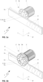
- Fig. 1a shows an embodiment of a part of a linear drive 1 in a perspective top view, which is not in accordance with the invention, but is helpful for understanding the linear drive according to the invention.
- the part of the linear drive 1 shown essentially comprises at least one primary part 5 designed as a reaction rail 5a with a return plate 5c, furthermore a secondary part 3, of which a first magnetic wheel 3a is shown, and a rotary drive 2, which is mechanically connected to the first magnetic wheel 3a.
- the first magnetic wheel 3a is equipped with magnets 4, in such a way that these magnets 4 generate a magnetic field that penetrates the reaction rail 5a and induce a number of eddy currents I 8 in this reaction rail 5a, which interact with the magnetic field, the magnetic field closing in a known manner via the return plate 5c of the primary part 5.
- the linear drive 1 is shown, which is also not in accordance with the invention but is helpful for understanding the linear drive according to the invention, wherein in addition to the first magnetic wheel 3a, at least one second magnetic wheel 3b of the secondary part 3 is shown, wherein the first and the second magnetic wheel 3a, 3b are arranged parallel to one another on a common axis 15 of the rotary drive 2, and wherein the first and the second magnetic wheel 3a, 3b are spaced apart from one another on this axis 15 in such a way that the at least one first reaction rail 5 can be arranged in a magnetically operative connection between them.
- the secondary part 3 and the first magnetic wheel 3a and the second magnetic wheel 3b are arranged horizontally, as in the Figures 4a to 4c is shown in more detail.
- the first and/or the second magnetic wheel 3a, 3b is/are equipped with magnets 4, in such a way that these magnets 4 generate the magnetic field B 6 between this first and this second magnetic wheel 3a, 3b, which magnetic field B 6 also penetrates the reaction rail 5a and thereby interacts with it.
- Fig. 1c shows additional possible arrangements of the magnets 4 on the first and second magnetic wheels 3a, 3b.
- the secondary part 3 is in Fig. 1c in a top view of the first magnetic wheel 3a and the second magnetic wheel 3b, whereby on one of the two the magnets 4a are designed as permanent magnets 4a and on the other as electromagnets 4b, optionally with a respective ferrite core 4c.
- Fig. 2a the secondary part 3 is shown in a simplified side view, whereby permanent magnets 4a facing each other are used, in Fig. 2b facing electromagnets 4b, in Fig. 2c facing permanent magnets 4a and electromagnets 4b. It is well known that for the purpose of expected magnetic field B 6 in Fig.
- adjacent magnets 4 on the respective first or second magnetic wheel 3a, 3b have a different polarity and also opposite magnets 4 on the one hand on the first magnetic wheel 3a and on the other hand on the second magnetic wheel 3b, provided that both are equipped with magnets 4 as in the Fig. 2a to 2c shown as an example.
- the magnetic field B 6 is shown using an example, which magnetic field B 6 is generated between the first and the second wheel 3a, 3b by the two associated magnets 4 with the polarities "N" and "S".
- the direction of the magnetic field B 6 changes to the respective adjacent magnet 4, although this is not explicitly shown here for the sake of simplicity; however, such magnet arrangements are sufficiently known in the technical field of electrical machines, so that such magnet arrangements can be assumed to be immediately and clearly known even without a more detailed pictorial representation than from the figures at hand.
- the rotary drive 2 sets the secondary part 3 in a rotating motion with the direction of rotation 7b, whereby the magnets 4 periodically rotate in and out of the area of the reaction rail 5a.
- FIG. 1a illustrates once again the mutually perpendicular current direction of the eddy currents I 8 to the magnetic field B 6 and the resulting force direction F 7a, which provides the translational drive.
- a necessary energy supply of the The power supply of the rotary drive 2 is not shown in detail here; an electrical supply, a hydraulic or a pneumatic supply or even a combination of two or three of the energy supply options mentioned can be provided for this power supply of the rotary drive 2.
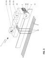
- Figure 3 it is shown that the secondary part 3 of the linear drive 1 with the rotary drive 2 is arranged on a support frame 11 of a drive platform 10 of a vehicle not shown in detail here, wherein a power supply 12, 12b of the linear drive 1 on the drive platform 10 can be provided via a number of current collectors 16 on busbars 9. Further examples of power supplies 12a or 12c are also indicated symbolically here; a more detailed explanation of the same does not appear necessary in view of expert knowledge.
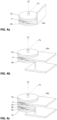
- Fig. 4a and 4b show examples of the linear drive 1 according to the invention, in which a horizontal arrangement of the secondary part 3 or the first and second magnetic wheels 3a, 3b is present.
- Fig. 4a For example, one leg of an L-profile beam 14a serves as a reaction rail and in Fig. 4b a leg of an H-profile beam 14b.
- a further force results during operation, namely a lifting force with a lifting force direction 13, which - as shown here - means a lifting of the first and second wheels 3a, 3b relative to the stationary L-profile support 14a or relative to the stationary H-profile support 14b.
- the Fig. 4c showed a further embodiment of the invention, in which, compared to the embodiment in Fig. 4b , a further second reaction rail 5b is shown, arranged parallel to the first reaction rail 5a, which is in operative connection with a further magnetic wheel 3c.
Landscapes
- Engineering & Computer Science (AREA)
- Power Engineering (AREA)
- Physics & Mathematics (AREA)
- Electromagnetism (AREA)
- Transportation (AREA)
- Mechanical Engineering (AREA)
- Chemical & Material Sciences (AREA)
- Combustion & Propulsion (AREA)
- Linear Motors (AREA)
- Dynamo-Electric Clutches, Dynamo-Electric Brakes (AREA)
Description
- Die vorliegende Erfindung fällt in den technischen Bereich von elektrischen Antrieben für spurgeführte Landverkehrsmittel bzw. Schienenfahrzeuge; sie betrifft vorliegend einen Linearantrieb für den Betrieb eines Fahrzeugs entlang eines Streckenabschnitts einer Fahrstrecke gemäss dem Oberbegriff des Anspruchs 1.
- Ein Linearantrieb oder Linearmotor ist eine elektrische Antriebsmaschine, bei der im Gegensatz zu bekannten, rotierenden Maschinen, die angetriebenen Objekte nicht in eine drehende Bewegung versetzt werden, sondern auf einer geradlinigen oder gekurvten Bahn verschoben werden. Konsequenterweise spricht man bei Linearantrieben also nicht von einer Rotationsbewegung, sondern von einer Translationsbewegung.
- Eine bekannte Anwendung solcher Linearantriebe liegt bei Achterbahnen seit Jahrzehnten vor; typischerweise werden dabei Achterbahnzüge im Zwei-Minuten-Takt von einem elektromagnetischen Linearantrieb in ein Schienenknäuel aus Stahlrohren katapultiert, wobei ein solcher tonnenschwere Achterbahnzug seine Initialenergie auf einer rund 50 Meter langen Katapultstrecke mittels etwa 100 paarweise installierten linearen Induktionsmotoren -auch LIM genannt- erhält. Ein solcher LIM war und ist dabei eine konsequente Weiterentwicklung eines kontaktlosen Beschleunigungssystems mit dem Ziel einer weitgehend mechanischen Wartungsfreiheit. Des Weiteren finden LIM auch in mechanischen Antrieben von Türsystemen -wie in Supermärkten beispielsweise- oder bei Personenbeförderungsbänder und Gepäckbändern an Flughäfen Verwendung.
- Auch andere elektromagnetische Funktionsprinzipien sind bei Achterbahnen von Interesse, und zwar werden dabei die linearen Induktionsmotoren abgelöst durch lineare Synchronmotoren -auch LSM genannt- deren Wirkungsgrad vergleichsweise höher ist als bei den LIM. Führende Anbieter von Achterbahnen greifen dabei vielfach auf durchschlagsstarke LSM Beschleunigungsbahnen zurück, die Spitzengeschwindigkeiten von rund 180 Stundenkilometern meistern.
- Der lineare Induktionsmotor entstammt in seiner Funktionsweise dem Wechselstrommotor. Der einzige und auffälligste Unterschied liegt darin, dass statt einer rotatorischen eine translatorische Bewegung erzeugt wird. Die im Wechselstrommotor kreisförmig angeordneten Statorspulen werden dazu auf einer ebenen, linearen Strecke platziert. Der "Läufer", der im Wechselstrommotor rotiert, wird beim linearen Synchronmotor über eine geradlinige Strecke bewegt. Wird durch einen Kupferdraht ein Strom geleitet, so entsteht um diesen ein magnetisches Feld. Dessen Feldstärke ist vom angelegten Strom abhängig. Um das erzeugte Magnetfeld zu maximieren und in seiner Ausbreitungsrichtung geometrisch zu kontrollieren, wird der Kupferdraht um einen länglichen Eisenkern -dem Ferritkern- gewickelt, wobei selbstverständlich auch eine eisenlose Ausführungsform denkbar ist. Es entsteht eine Spule, welche bei angelegtem Strom gleiche Eigenschaften wie ein Permanentmagnet besitzt. An den jeweiligen Enden des Ferritkerns entsteht ein Nord- und ein Südpol. Beim Linearmotor sind viele derartige Spulen in einer Reihe hintereinandergeschaltet. Entlang einer Schiene sind dazu über eine gesamte Beschleunigungsstrecke bzw. Katapultstrecke Motormodule mit dreiphasigen Spulen -den Statoren- angeordnet, die um einen etwa 20 Millimeter breiten linearen Luftspalt gruppiert sind. Der Motor besitzt dabei eine Länge von etwa einem Meter. Am Zug befindet sich eine Kupfer- oder Aluminiumschiene als Reaktionsschiene als sogenannter Läufer, welche Reaktionsschiene vom LIM Motor berührungslos durch den Spalt gezogen wird. Das Funktionsprinzip des Antriebs folgt dabei dem Gesetz der Induktion. Eine angelegte Wechselspannung erzeugt in den Spulen des Linearmotors ein wanderndes Magnetfeld mit ständigem Wechsel der Polarität zwischen Nord und Süd. Das Wanderfeld bewegt sich entlang der Katapultstrecke, seine Fortbewegungsgeschwindigkeit wird durch die Frequenz des angelegten Stroms bestimmt. Das im Stator angelegte magnetische Wanderfeld induziert im "Läufermedium" eine elektrische Spannung, die die freien Elektronen in der Reaktionsschiene in Bewegung versetzt. Dieser Elektronenfluss erzeugt wiederum ein Magnetfeld. Beide Magnetfelder interagieren miteinander, ungleiche Pole ziehen sich an, gleiche Pole stoßen sich ab. Durch die Wechselwirkung der beiden Magnetfelder entsteht eine Kraftkomponente in Richtung des Wanderfeldes, welche den Achterbahnzug in Bewegung setzt. Die translatorische Antriebskraft ist vorliegend abhängig von der Relativgeschwindigkeit Δv zwischen dem Zug und dem Wandermagnetfeld. Sind beide gleich schnell, wird kein Gegenmagnetfeld erzeugt und die Beschleunigung ist gleich null.
- Während der Beschleunigungsphase ist die Geschwindigkeit des Zuges -und damit des Läufer- stets kleiner als die des antreibenden Statorfeldes. Das in den Läufern erzeugte Magnetfeld bewegt sich also über die Reaktionsschiene und springt sogar über benachbarte Reaktionsschienen von Wagen zu Wagen. Würden die Geschwindigkeiten des Statorfeldes und des Zuges gleich sein, so würde im Läufer keine Spannung induziert und die den Zug antreibende Kraft nicht mehr aufrechterhalten. Würde die Geschwindigkeit des Zuges sogar größer als die des Statorfeldes, so würde die Kraftrichtung drehen und der Zug abgebremst werden. Derartige Zusammenhänge resultieren bekanntermassen aus dem physikalischen Induktionsgesetz.
- Einen bekannten Linearantrieb offenbart die Druckschrift
EP 3 107 195 A1 ; sie betrifft ein Linearmotorantriebssystem zur Beschleunigung eines Fahrzeugs innerhalb eines Beschleunigungsabschnitts auf einer Fahrtrasse. Das Linearmotorantriebssystem umfasst einen Stator mit mindestens zwei längs der Fahrtrasse angeordneten Statorelementen, wobei die Statorelemente zu Statorgruppen zusammengefasst sind. Ferner umfasst das Linearmotorantriebssystem einen Läufer, welcher am Fahrzeug befestigt ist. Dabei ist jede Statorgruppe mit einem eigenen Energiewandler zur Energieversorgung permanent verbunden, welcher Energiewandler einzeln angesteuert werden kann. Mindestens zwei der Statorgruppen sind derart angeordnet, dass der Läufer gleichzeitig mit diesen zwei Statorgruppen wechselwirken kann. Das hier vorliegende Linearmotorantriebssystem ist zur Beschleunigung eines Fahrzeugs zum Personentransport in einer Vergnügungsanlage wie beispielsweise einer Achterbahn geeignet. In der DruckschriftEP 2 269 289 B1 wird eine Transportvorrichtung auf der Basis eines Wirbelstromantriebs beschrieben. Die Vorrichtung umfasst eine Schiene und zwei parallel angeordnete Drehscheiben, die von einem Elektromotor angetrieben werden. Die Drehscheiben sind um ihren Umfang mit Magneten versehen. Der Antrieb ist z. B. für schienengeführte Wagen vorgesehen. Weiter ist aus der DruckschriftUS 2003/205163 A1 ein System beschrieben, mit dem Wagen zum Schweben gebracht und beschleunigt werden können. In der DruckschriftWO 2015/191935 A1 ist ein Antrieb und eine Steuerung für ein magnetisches Anheben eines Fahrzeugs beschrieben. Ein Schwebetriebwerk weist hierfür rotierende Scheiben auf, die mit Magneten versehen sind, und in einer Basis Wirbelströme induzieren. Die DruckschriftJP H09 261805 A - Es ist Aufgabe der vorliegenden Erfindung, einen Linearantrieb dahingehend weiterzuentwickeln, dass ein einfacherer und effizienterer Systemaufbau dieses Linearantriebs ermöglicht wird, der eine raumsparendere Gesamtsysteminstallation im Vergleich zu herkömmlichen Linearantrieben aufweist.
- Die dieser Erfindung für den Linearantrieb zugrundeliegende Aufgabe wird gelöst durch die Merkmale des Anspruchs 1; die diesen Erfindungsgedanken weiterbildenden Merkmale sind Gegenstand der Unteransprüche 2 bis 11.
- Der Kern der vorliegenden Erfindung ist darin zu sehen, dass ein Linearantrieb ein Primärteil und ein hierzu magnetisch in Wirkverbindung stehendes Sekundärteil umfasst, wobei das Primärteil als mindestens eine erste Reaktionsschiene ausgebildet ist und das Sekundärteil eine Anzahl Magnete umfasst, wobei das Sekundärteil ein erstes magnetisches Rad und mindestens ein hierzu parallel angeordnetes, zweites magnetisches Rad umfasst und die Anzahl Magnete an dem ersten magnetischen Rad und dem zweiten magnetischen Rad angeordnet sind, und wobei die mindestens eine erste Reaktionsschiene zwischen dem ersten magnetischen Rad und dem zweiten magnetischen Rad angeordnet ist und mit diesen magnetisch wirkverbunden ist. Das Sekundärteil ist mit einem Rotationsantrieb mechanisch verbunden, so dass, bei Inbetriebnahme des Linearantriebs, durch Rotation des Sekundärteils Wirbelströme in der Reaktionsschiene entstehen, wobei eine Antriebskraft resultiert und das Sekundärteil relativ zum Primärteil translatorisch angetrieben wird. Das Sekundärteil sowie das erste magnetische Rad (3a) und das zweite magnetische Rad (3b) sind horizontal angeordnet. Bei Inbetriebnahme des Linearantriebs, resultiert neben der translatorischen Antriebskraft eine weitere Hubkraft, die zu einer Anhebung der ersten und zweiten Räder gegenüber dem Primärteil führt.
- Zusammenfassend ist festhaltbar, dass die durch die Magnete am Umfang des Sekundärteils wechselweise ausgerichteten Magnetfelder durch die Rotation des Rotationsantriebs gegenüber dem Primärteil derart in Bewegung sind, dass sich in dem als Reaktionsschiene ausgestalteten Primärteil Wirbelströme I ausbilden, die wiederum in Verbindung mit diesen wechselweise ausgerichteten Magnetfeldern derart wechselwirken, dass folglich eine gewünschte, mechanische Kraft bereitgestellt wird; dem Primärteil wird also mittels des rotierbaren Sekundärteils "quasi eine unendliche Längenausdehnung desselben vorgetäuscht". Somit umfasst die eine Teilsysteminstallation hinsichtlich des Sekundärteils im Wesentlichen die Magneträder mit dem sie antreibenden Rotationsantrieb in einer kompakten Einheit, die in einem Bereich eines Fahrzeugs konzentriert angeordnet werden kann und darüber hinaus über die gesamte Fahrstrecke nutzbar zur Verfügung steht und an jeder Stelle der Fahrstrecke, an dem das Primärteil angeordnet ist, mit diesem in Wechselwirkung treten, und zwar sowohl (positiv) beschleunigend als auch bremsend. Selbstverständlich sind pro Fahrzeug auch mehrere dieser Magnetradsysteme installierbar, womit die gesamte Systemleistung erhöht werden kann und/oder die mehreren Antriebseinheiten bei vorgegebener Gesamtsystemleistung kleiner ausgeführt werden können.
- Besonders vorteilhaft ist dabei, dass mit der Erfindung ein massgeblich kürzerer Sekundärteil in Bezug auf die Länge bekannter Fahrzeuge möglich ist als herkömmliche Sekundärteile, die häufig auch annähernd entlang einer gesamten Fahrzeuglänge angeordnet werden.
- Mittels einer steuerbaren Rotationsgeschwindigkeit des Rotationsantriebs, ist der Betrag der Vortriebskraft einstellbar; die Drehrichtung -vorwärts bzw. rückwärts in Bezug auf eine Fahrtrichtung eines Fahrzeugs- bestimmt die Art der Beschleunigung im Sinne einer Geschwindigkeitserhöhung bzw. einer Geschwindigkeitsreduktion.
- Das als Reaktionsschiene ausgebildete Primärteil ist für die Ausbildung der notwendigen Wirbelströme I aus einem elektrisch leitenden Material hergestellt; beispielsweise kann die Reaktionsschiene aus Kupfer oder dem dazu vergleichsweise schlechter leitenden Aluminium hergestellt sein, welches mit Vorteil deutlich leichter und auch preiswerter ist; auch andere elektrisch leitende Materialen können zum Einsatz gelangen.
- Die vorliegend einfache Ausführung der Teilsysteminstallation hinsichtlich des Primärteils, nämlich als einfache Reaktionsschiene, erlaubt nun die Ausstattung einer gesamten Fahrstrecke eines herkömmlichen Fahrgeschäfts mit einer solchen Reaktionsschiene, womit die Fahrzeuggeschwindigkeit permanent steuerbar ist.
- Gegenüber dem Stand der Technik stellt die Erfindung nun erstmalig einen Linearantrieb zur Verfügung, dessen Gesamtsysteminstallation markant einfacher ausführbar ist und bei dessen Betrieb sich der Energieverbrauch nicht mehr nur auf herkömmliche einzelne Beschleunigungsstreckenabschnitte konzentrieren muss, sondern über die gesamte Fahrstrecke verteilbar ist.
- Bei der Erfindung ist vorgesehen, dass das Sekundärteil das erste magnetische Rad und ein parallel dazu angeordnetes zweites magnetisches Rad umfasst, wobei die mindestens eine erste Reaktionsschiene zwischen dem ersten magnetischen Rad und dem zweiten magnetischen Rad angeordnet ist und mit beiden Rädern magnetisch wirkverbunden ist, wie oben beschrieben. Dabei sind das Sekundärteil sowie das erste magnetische Rad und das zweite magnetische Rad horizontal angeordnet und das Sekundärteil ist mit einem Rotationsantrieb mechanisch verbunden.
- Nach der Erfindung ist vorgesehen, dass die Magnete auf einer der Reaktionsschiene zugewandten Seite des ersten magnetischen Rads und des zweiten magnetischen Rads angeordnet sind. Dabei ist vorgesehen, dass einander gegenüberstehende Magnete am ersten und zweiten Rad eine unterschiedliche Polung aufweisen und benachbarte Magnete auf einem jeweiligen Rad ebenso.
- Bei einer Ausführungsform der Erfindung ist vorgesehen, dass das Primärteil ortsfest angeordnet ist und das Sekundärteil beweglich. Ferner kann bei einer weiteren Ausführungsform vorgesehen sein, dass das Sekundärteil ortsfest angeordnet ist und das Primärteil beweglich. Mit Vorteil sind die Magnete bei einer weiteren Ausführungsform als Permanentmagnete ausgebildet, oder die Magnete sind als fremderregte Elektromagnete ausgebildet.
- Zecks Erhöhung der magnetischen Wirkung kann ferner vorgesehen sein, dass die als fremderregte Elektromagnete ausgebildeten Magnete einen Ferritkern umfassen.
- Eine vorteilhafte Ausführungsform sieht vor, dass das Sekundärteil und der Rotationsantrieb auf einer Antriebsplattform angeordnet sind, wodurch eine möglichst kompakte Einheit bereitstellbar ist.
- Vorteilhafterweise weist der Linearantrieb in einer Ausführungsform eine magnetische Wirkverbindung zwischen dem Primärteil und dem Sekundärteil als eine asynchrone Kopplung auf, wobei im Primärteil eine Anzahl Wirbelströme I induzierbar sind.
- Bei einer weiteren vorteilhaften Ausführungsform der Erfindung ist vorgesehen, dass das Primärteil die mindestens eine Reaktionsschiene und parallel dazu eine mindestens zweite Reaktionsschiene umfasst, welche mit dem Sekundärteil magnetisch in Wirkverbindung stehen, wobei das Sekundärteil das erste und das zweite magnetische Rad und zudem mindestens ein drittes magnetisches Rad umfasst; durch diese Parallelanordnung zweier -oder gegebenenfalls mehrerer- Reaktionsschienen, kann in einer konzentrierten Bauform die Gesamtsystemleistung erhöht werden.
- Ferner kann bei einer weiteren Ausführungsform des erfindungsgemäßen Linearantriebs vorgesehen sein, den Rotationsantrieb als eine elektrische oder als eine hydraulische oder als eine pneumatische Maschine auszubilden oder dass der Rotationsantrieb als ein kombinierter Antrieb aus der Gruppe elektrischer, hydraulischer oder pneumatischer Maschinen ausbildbar ist.
- Weitere Ausführungsformen des erfindungsgemäßen Linearantriebs und deren zugehörigen Vorteile sind Gegenstand der detaillierten Beschreibung und der Figuren.
- Im Folgenden wird die Erfindung anhand von Figuren beispielhaft erläutert. Gleiche Gegenstände sind in den Figuren grundsätzlich mit gleichen Bezugszeichen versehen. An dieser Stelle wird darauf hingewiesen, dass die Figuren keine einschränkende Wirkung auf den vorliegenden Erfindungsgegenstand als solches haben, sondern lediglich exemplarische Ausführungsformen des Erfindungsgedankens -wie dieser sich in den Ansprüchen darstellt- zeigen.
- Es zeigen rein schematisch die
-
Fig.1a, 1b und1c einen nicht erfindungsgemäßen Linearantrieb mit einem als Reaktionsschiene ausgebildeten Primärteil und ein Sekundärteil, welches ein erstes magnetisches Rad, bzw. ein erstes und ein zweites magnetisches Rad umfasst, die inFig. 1c detaillierter dargestellt sind; -
Fig. 2a bis Fig. 2c Ausführungsformen des Linearantriebs basierend aufFig. 1a mit unterschiedlich ausgestatteten magnetischen Tragrädern; -
Fig. 3 eine weitere Ausführungsform des Linearantriebs gemässFig. 1a , wobei dieser auf einer Antriebplattform eines -nicht näher dargestellten- Fahrzeugs angeordnet ist, und -
Fig. 4a, 4b, 4c Ausführungsformen des erfindungsgemäßen Linearantriebs basierend aufFig. 1a , wobei dessen magnetische Tragräder vorliegend horizontal angeordnet sind. -
Fig. 1a zeigt eine Ausführungsform eines Teil eines Linearantriebs 1 in einer perspektivischen Draufsicht, die zwar nicht erfindungsgemäß ist, jedoch zum Verständnis des Linearantriebs nach der Erfindung hilfreich ist. Der dargestellte Teil des Linearantriebs 1 umfasst im Wesentlichen mindestens ein als eine Reaktionsschiene 5a ausgebildetes Primärteil 5 mit einer Rückschlussplatte 5c, ferner ein Sekundärteil 3, von dem ein erstes magnetisches Rad 3a gezeigt ist und ein Rotationsantrieb 2, der mechanisch mit dem ersten magnetischen Rad 3a verbunden ist. Das erste magnetische Rad 3a ist mit Magneten 4 bestückt, und zwar derart, dass diese Magnete 4 ein die Reaktionsschiene 5a durchdringendes magnetisches Feld erzeugen und in dieser Reaktionsschiene 5a eine Anzahl Wirbelströme I 8 induzieren, welche mit dem magnetischen Feld wechselwirken, wobei sich das magnetische Feld in bekannter Weise über die Rückschlussplatte 5c des Primärteils 5 schliesst. - In der
Fig. 1b ist der ebenfalls nicht erfindungsgemäße, jedoch zum Verständnis des erfindungsgemäßen Linearantriebs hilfreiche Linearantrieb 1 gezeigt, wobei zusätzlich zu dem ersten magnetische Rad 3a mindestens ein zweites magnetisches Rad 3b des Sekundärteils 3 dargestellt ist, wobei das erste und das zweite magnetische Rad 3a, 3b auf einer gemeinsamen Achse 15 des Rotationsantriebs 2 parallel zueinander angeordnet sind, und wobei das erste und das zweite magnetische Rad 3a, 3b auf dieser Achse 15 derart voneinander beabstandet sind, dass dazwischen die mindestens eine erste Reaktionsschiene 5 magnetisch wirkverbunden anordenbar ist. Nach der Erfindung sind das Sekundärteil 3 sowie das erste magnetische Rad 3a und das zweite magnetische Rad 3b horizontal angeordnet, wie in denFiguren 4a bis 4c genauer dargestellt ist. - Das erste und/oder das zweite magnetische Rad 3a, 3b ist/sind mit Magneten 4 bestückt, und zwar derart, dass diese Magnete 4 das magnetische Feld B 6 zwischen diesem ersten und diesem zweiten magnetischen Rad 3a, 3b erzeugt, welches magnetische Feld B 6 ebenfalls die Reaktionsschiene 5a durchdringt und dabei mit dieser wechselwirkt.
Fig. 1c zeigt ergänzend hierzu mögliche Anordnungen der Magnete 4 an dem ersten und dem zweiten magnetischen Rad 3a, 3b. Vorliegend ist das Sekundärteil 3 inFig. 1c in einer Draufsicht auf das erste magnetisches Rad 3a und auf das zweite magnetisches Rad 3b gezeigt, wobei an einem der beiden die Magnete 4a als Permanentmagnete 4a ausgebildet sind und am anderen als Elektromagnete 4b, gegebenenfalls mit einem jeweiligen Ferritkern 4c. Bei der Auslegung des Linearantriebs 1 ist zu bestimmen, welche Art von Magneten 4 zum Einsatz gelangen, Permanentmagnete 4a und/oder Elektromagnete 4b mit oder ohne Ferritkern 4c. In diesem Zusammenhang ist ein Blick auf dieFig. 2a bis 2c ergänzend hilfreich: So ist nämlich inFig. 2a das Sekundärteil 3 in einer Seitenansicht vereinfacht dargestellt, wobei hier einander zugewandte Permanentmagnete 4a zum Einsatz gelangen, inFig. 2b einander zugewandte Elektromagnete 4b, inFig. 2c einander zugewandte Permanentmagnete 4a und Elektromagnete 4b. Hinlänglich bekannt ist, dass zwecks erwartetem magnetischem Feld B 6 inFig. 1b , jeweils benachbarte Magnete 4 auf dem jeweiligen ersten oder zweiten magnetischen Rad 3a, 3b, eine unterschiedliche Polarität aufweisen und ebenso einander gegenüberliegende Magnete 4 zum einen auf dem ersten magnetischen Rad 3a und zum anderen auf dem zweiten magnetischen Rad 3b, sofern denn beide mit Magneten 4 ausgestattet sind wie in denFig. 2a bis 2c beispielhaft gezeigt. InFig. 1b ist das magnetische Feld B 6 anhand eines Beispiels gezeigt, welches magnetische Feld B 6 zwischen dem ersten und dem zweiten Rad 3a, 3b durch die beiden zugehörigen Magnete 4 mit den Polaritäten "N" bzw. "S" erzeugt wird. In Umfangsrichtung des ersten und des zweiten magnetischen Rads 3a, 3b wechselt die Richtung des magnetischen Feldes B 6 zum jeweils benachbarten Magnet 4, wobei dies vorliegend der Einfachheit halber nicht explizit dargestellt ist; allerdings sind solche Magnetanordnungen im technischen Gebiet der elektrischen Maschinen hinreichend bekannt, sodass solche Magnetanordnungen auch ohne detailliertere bildliche Darstellung als aus den vorliegenden Figuren -unmittelbar und eindeutigbekannt voraussetzbar sind. - Bei Inbetriebnahme des Linearantriebs 1 wird mit dem Rotationsantrieb 2 das Sekundärteil 3 in eine rotierende Bewegung mit der Drehrichtung 7b versetzt, womit die Magnete 4 periodisch in den Bereich der Reaktionsschiene 5a eindrehen und wieder herausdrehen. Dabei entstehen in der Reaktionsschiene 5a Wirbelströme 8, deren Stromrichtungen sich aus den Richtungen des jeweiligen magnetischen Feldes B 6 ergeben; jeder induzierte Wirbelstrom 8 ist dabei so ausgerichtet, dass das hierdurch induzierte Wirbelstrommagnetfeld dem magnetischen Feld B 6 entgegenzuwirken versucht, wobei eine abstossende Kraft mit der Kraftrichtung 7a resultiert und das Sekundärteil 3 gegenüber dem Primärteil 5 translatorisch angetrieben wird. Das Koordinatensystem 17 in
Fig. 1a verdeutlicht hier nochmals die zueinander senkrecht ausgerichtete Stromrichtung der Wirbelströme I 8 zum magnetischen Feld B 6 und die resultierende Kraftrichtung F 7a, die für den translatorischen Antrieb sorgt. Eine notwendige Energieversorgung des Rotationsantriebs 2 ist hier nicht näher gezeigt; für diese Energieversorgung des Rotationsantriebs 2 kann eine elektrische Versorgung vorgesehen sein, eine hydraulische oder eine pneumatische oder gar eine Kombination aus zwei oder drei der genannten Energieversorgungsmöglichkeiten. InFigur 3 ist gezeigt, dass das Sekundärteil 3 des Linearantriebs 1 mit dem Rotationsantrieb 2 an einem Trägerrahmen 11 einer Antriebsplattform 10 eines hier nicht näher gezeigten Fahrzeugs angeordnet ist, wobei über eine Anzahl Stromabnehmer 16 an Stromschienen 9 eine Energieversorgung 12, 12b des Linearantriebs 1 auf der Antriebsplattform 10 erfolgen kann. Weitere Beispiele für Energieversorgungen 12a oder 12c sind hier zusätzlich symbolisch angedeutet, eine nähere Erläuterung derselben erscheint mit Blick auf fachmännisches Wissen nicht notwendig. - Der guten Ordnung halber sei an dieser Stelle angemerkt, dass es -ohne den Erfindungsgedanken zu verlassen- wahlweise möglich ist, das Primärteil 5 oder das Sekundärteil 3 ortsfest auszuführen und das jeweils andere Teil beweglich. Selbstverständlich ist im Fahrbetrieb auch denkbar, durch einen Drehrichtungswechsel des Rotationsantriebs 2 eine Bremsung einzuleiten und -sofern Elektromagnete 4b am Sekundärteil 3 angeordnet sind- auch eine zumindest teilweise Rekuperation der Bremsenergie vorzunehmen.
- Die
Fig. 4a und 4b zeigen Beispiele des erfindungsgemäßen Linearantriebs 1, bei dem eine horizontale Anordnung des Sekundärteils 3 bzw. des ersten und zweiten magnetischen Rads 3a, 3b vorliegt. InFig. 4a dient beispielsweise ein Schenkel eines L-Profil-Trägers 14a als Reaktionsschiene und inFig. 4b ein Schenkel eines H-ProfilTrägers 14b. Abgesehen von der anhand derFig. 1a diskutierten Funktionsweise für den translatorischen Antrieb in Kraftrichtung F 7a, siehe auchFig. 1a , resultiert im Betrieb eine weitere Kraft, namentlich eine Hubkraft mit einer Hubkraftrichtung 13, die -wie hier gezeigt- für das erste und das zweite Rad 3a, 3b eine Anhebung gegenüber dem ortsfesten L-Profil-Träger 14a bzw. gegenüber dem ortsfesten H-Profil-Träger 14b bedeutet. Bei einer entsprechenden Dimensionierung und Ausgestaltung ist somit ein Anheben eines Fahrzeugs denkbar, womit nicht nur der Energiebedarf bei laufendem Betrieb reduzierbar ist, sondern zudem der Verschleiss, insbesondere in Bereichen hoher Fahrzeuggeschwindigkeiten. Rein informatorisch sei angemerkt, dass mit dem erfindungsgemäßen Linearantrieb Fahrzeuggeschwindigkeiten erzielbar sind, die deutlich über 200 Stundenkilometern liegen. - Die
Fig. 4c zeigte eine weitere Ausführungsform der Erfindung, bei welcher im Vergleich zu der Ausführungsform inFig. 4b , eine weitere, parallel zur ersten Reaktionsschiene 5a angeordnete, zweite Reaktionsschiene 5b gezeigt ist, die mit einem weiteren magnetischen Rad 3c in Wirkverbindung steht. -
- 1
- Linearantrieb
- 2
- Rotationsantrieb
- 3, 3a, 3b, 3c
- Sekundärteil; erstes, zweites, drittes magnetisches Rad
- 4, 4a, 4b
- Magnete, Permanentmagnete, Elektromagnete, mit N=Nordpol und S=Südpol
- 4c
- Ferritkern für Elektromagnete
- 5, 5a, 5b, 5c
- Primärteil, erste bzw. zweite Reaktionsschiene, Rückschussplatte
- 6
- magnetisches Feld B, mit N=Nordpol und S=Südpol
- 7a
- Kraftrichtung (F) von 3, translatorisch
- 7b
- Drehrichtung von 3
- 8
- Wirbelströme I in 5
- 9
- Stromschienen zur Speisung von 2
- 10
- Antriebsplattform (für ein Fahrzeug)
- 11
- Trägerrahmen
- 12, 12a, 12b, 12c
- Energieversorgung
- 13
- Hubkraftrichtung (Levitation)
- 14a
- L-Profil-Träger für 5
- 14b
- H-Profil-Träger für 5
- 15
- Achse
- 16
- Stromabnehmer an 9
- 17
- Koordinatensystem
Claims (10)
- Linearantrieb (1), umfassend ein Primärteil (5) und ein hierzu magnetisch in Wirkverbindung stehendes Sekundärteil (3), wobei das Primärteil (5) mindestens eine erste elektrisch leitende Reaktionsschiene (5a) und das Sekundärteil (3) eine Anzahl Magnete (4) umfasst, wobei das Sekundärteil (3) ein erstes magnetisches Rad (3a) und mindestens ein hierzu parallel angeordnetes, zweites magnetisches Rad (3b) umfasst und die Anzahl Magnete (4) an dem ersten magnetischen Rad (3a) und dem zweiten magnetischen Rad (3b) angeordnet sind, wobei die mindestens eine erste Reaktionsschiene (5a) zwischen dem ersten magnetischen Rad (3a) und dem zweiten magnetischen Rad (3b) angeordnet ist und mit diesen magnetisch wirkverbunden ist, wobei das Sekundärteil (3) mit einem Rotationsantrieb (2) mechanisch verbunden ist, so dass, bei Inbetriebnahme des Linearantriebs (1), in der Reaktionsschiene (5a) durch Rotation des Sekundärteils Wirbelströme (8) entstehen, wobei eine Antriebskraft (7a) resultiert, wobei das Sekundärteil (3) relativ zum Primärteil (5) translatorisch angetrieben wird, dadurch gekennzeichnet, dass das Sekundärteil (3) sowie das erste magnetische Rad (3a) und das zweite magnetische Rad (3b) horizontal angeordnet sind, so dass, bei Inbetriebnahme des Linearantriebs (1), neben der translatorischen Antriebskraft (7a) eine weitere Hubkraft (13) resultiert, die zu einer Anhebung der ersten und zweiten Räder (3a, 3b) gegenüber dem Primärteil (5) führt.
- Linearantrieb (1) nach Anspruch 1, dadurch gekennzeichnet, dass das Primärteil (5) neben der mindestens einen ersten Reaktionsschiene (5a) parallel dazu mindestens eine zweite Reaktionsschiene (5b) aufweist, und das Sekundärteil (3) neben dem mindestens einen ersten magnetischen Rad (3a) und dem mindestens einen zweiten magnetischen Rad (3b) ein zu beiden parallel angeordnetes, drittes magnetisches Rad (3c) umfasst, wobei die mindestens eine zweite Reaktionsschiene (5b) zwischen dem zweiten magnetischen Rad (3b) und dem dritten magnetischen Rad (3c) angeordnet ist und mit letzteren magnetisch wirkverbunden ist.
- Linearantrieb (1) nach Anspruch 2, dadurch gekennzeichnet, dass an dem mindestens einen zweiten magnetischen Rad (3b) und/oder an dem dritten magnetischen Rad (3c) eine Anzahl Magnete (4) angeordnet sind.
- Linearantrieb (1) nach einem der Ansprüche 1 bis 3, dadurch gekennzeichnet, dass das Primärteil (5) ortsfest angeordnet ist und das Sekundärteil (3) beweglich.
- Linearantrieb (1) nach einem der Ansprüche 1 bis 3, dadurch gekennzeichnet, dass das Sekundärteil (3) ortsfest angeordnet ist und das Primärteil (5) beweglich.
- Linearantrieb (1) nach einem der vorhergehenden Ansprüche, dadurch gekennzeichnet, dass die Magnete (4) als Permanentmagnete ausgebildet sind.
- Linearantrieb (1) nach einem der vorhergehenden Ansprüche 1 bis 6, dadurch gekennzeichnet, dass die Magnete (4) als fremderregte Elektromagnete ausgebildet sind.
- Linearantrieb (1) nach Anspruch 7, dadurch gekennzeichnet, dass die als fremderregte Elektromagnete ausgebildeten Magnete (4) einen Ferritkern (4c) umfassen.
- Linearantrieb (1) nach einem der vorhergehenden Ansprüche, dadurch gekennzeichnet, dass das Sekundärteil (3) und der Rotationsantrieb (2) auf einer Antriebsplattform (10) angeordnet sind.
- Linearantrieb (1) nach einem der vorhergehenden Ansprüche, dadurch gekennzeichnet, dass der Rotationsantrieb (2) als eine elektrische oder als eine hydraulische oder als eine pneumatische Maschine ausgebildet ist oder dass der Rotationsantrieb (2) als ein kombinierter Antrieb aus der Gruppe elektrischer, hydraulischer oder pneumatischer Maschinen ausgebildet ist.
Priority Applications (7)
| Application Number | Priority Date | Filing Date | Title |
|---|---|---|---|
| EP21171873.9A EP4087103B1 (de) | 2021-05-03 | 2021-05-03 | Linearantrieb |
| PL21171873.9T PL4087103T3 (pl) | 2021-05-03 | 2021-05-03 | Napęd liniowy |
| ES21171873T ES3024370T3 (en) | 2021-05-03 | 2021-05-03 | Linear drive |
| US18/558,255 US20240223059A1 (en) | 2021-05-03 | 2022-05-03 | Linear drive for track-guided means of land transportation or railway vehicles |
| CN202280032184.2A CN117242683A (zh) | 2021-05-03 | 2022-05-03 | 线性驱动器 |
| CA3215140A CA3215140A1 (en) | 2021-05-03 | 2022-05-03 | Linear drive |
| PCT/EP2022/061769 WO2022233822A1 (en) | 2021-05-03 | 2022-05-03 | Linear drive |
Applications Claiming Priority (1)
| Application Number | Priority Date | Filing Date | Title |
|---|---|---|---|
| EP21171873.9A EP4087103B1 (de) | 2021-05-03 | 2021-05-03 | Linearantrieb |
Publications (2)
| Publication Number | Publication Date |
|---|---|
| EP4087103A1 EP4087103A1 (de) | 2022-11-09 |
| EP4087103B1 true EP4087103B1 (de) | 2025-02-12 |
Family
ID=75787008
Family Applications (1)
| Application Number | Title | Priority Date | Filing Date |
|---|---|---|---|
| EP21171873.9A Active EP4087103B1 (de) | 2021-05-03 | 2021-05-03 | Linearantrieb |
Country Status (7)
| Country | Link |
|---|---|
| US (1) | US20240223059A1 (de) |
| EP (1) | EP4087103B1 (de) |
| CN (1) | CN117242683A (de) |
| CA (1) | CA3215140A1 (de) |
| ES (1) | ES3024370T3 (de) |
| PL (1) | PL4087103T3 (de) |
| WO (1) | WO2022233822A1 (de) |
Family Cites Families (13)
| Publication number | Priority date | Publication date | Assignee | Title |
|---|---|---|---|---|
| US3616762A (en) * | 1968-09-25 | 1971-11-02 | Linerail Manutention Par Moteu | Overhead conveyor system |
| DE3601963A1 (de) * | 1985-01-26 | 1986-07-31 | Kabushiki Kaisha Toshiba, Kawasaki, Kanagawa | Transportanordnung |
| JPH05336616A (ja) * | 1991-11-22 | 1993-12-17 | Aqueous Res:Kk | 車両用駆動装置及び二元推進式車両 |
| JPH09261805A (ja) * | 1996-03-19 | 1997-10-03 | Yaskawa Electric Corp | 磁気浮上アクチュエータ |
| CA2370416C (en) * | 2001-02-07 | 2010-01-26 | Denipro Ag | Conveyor system |
| US7204192B2 (en) * | 2001-07-02 | 2007-04-17 | Magna Force, Inc. | Apparatus, systems and methods for levitating and moving objects |
| US7002223B2 (en) * | 2001-07-27 | 2006-02-21 | Samsung Electronics Co., Ltd. | Semiconductor device having elevated source/drain |
| CA2457999A1 (en) * | 2004-02-17 | 2005-08-17 | Michel Paradis | Track belt guide wheels assembly |
| DE102008019319B4 (de) * | 2008-04-16 | 2011-07-07 | SEW-EURODRIVE GmbH & Co. KG, 76646 | Transportvorrichtung |
| US9126487B2 (en) * | 2013-03-15 | 2015-09-08 | Arx Pax, LLC | Hoverboard which generates magnetic lift to carry a person |
| CA2951903A1 (en) * | 2014-06-11 | 2015-12-17 | Arx Pax Labs, Inc | Propulsion and control for a magnetically lifted vehicle |
| EP3107195A1 (de) | 2015-06-16 | 2016-12-21 | InDriveTec AG | Linearmotorantriebssystem |
| DE102015226139A1 (de) * | 2015-12-21 | 2017-06-22 | Krones Ag | Lineares Transportsystem mit minimaler Transportteilung |
-
2021
- 2021-05-03 PL PL21171873.9T patent/PL4087103T3/pl unknown
- 2021-05-03 ES ES21171873T patent/ES3024370T3/es active Active
- 2021-05-03 EP EP21171873.9A patent/EP4087103B1/de active Active
-
2022
- 2022-05-03 WO PCT/EP2022/061769 patent/WO2022233822A1/en not_active Ceased
- 2022-05-03 CA CA3215140A patent/CA3215140A1/en active Pending
- 2022-05-03 CN CN202280032184.2A patent/CN117242683A/zh active Pending
- 2022-05-03 US US18/558,255 patent/US20240223059A1/en active Pending
Also Published As
| Publication number | Publication date |
|---|---|
| CA3215140A1 (en) | 2022-11-10 |
| PL4087103T3 (pl) | 2025-06-09 |
| US20240223059A1 (en) | 2024-07-04 |
| ES3024370T3 (en) | 2025-06-04 |
| EP4087103A1 (de) | 2022-11-09 |
| WO2022233822A1 (en) | 2022-11-10 |
| CN117242683A (zh) | 2023-12-15 |
Similar Documents
| Publication | Publication Date | Title |
|---|---|---|
| EP2150434B1 (de) | Fahrzeug mit einer wirbelstrombremse für ein spurgebundenes verkehrssystem und damit betriebenes verkehrssystem, insbesondere magnetschwebebahn | |
| EP2099640B1 (de) | Magnetschwebefahrzeug mit wenigstens einem magnetsystem | |
| EP0234543B1 (de) | Magnetkraftsystem für reibungsarmen Transport von Lasten | |
| EP1851408B1 (de) | Schiebetür mit einem magnetischen antriebssystem mit einem wegmesssystem | |
| EP2219900A2 (de) | Magnetschwebebahn mit nutschrägung | |
| DE2164078A1 (de) | Antriebsanordnung mit einem nach art einer synchronmaschine ausgebildeten linearmotor | |
| EP2485916A2 (de) | Beförderungssystem mit elektromagnetischer bremse | |
| DE102004013994A1 (de) | Magnetschwebebahn mit einer Wirbelstrombremse | |
| EP0052346A2 (de) | Elektrischer Antrieb oder Generator | |
| DE4222167C2 (de) | Magnetschwebebahn mit Supraleitung sowie dafür vorgesehene Stromzuleitungseinrichtung | |
| DE112017007591B4 (de) | Stromversorgungssystem einer Magnetschwebebahn | |
| EP0986490A1 (de) | Fahrsystem für ein magnetschwebefahrzeug | |
| WO2016128130A1 (de) | Schienengebundene magnetschwebebahn | |
| DE2614883A1 (de) | Schienenfahrzeug mit magnetischer unterstuetzung | |
| DE2710156C2 (de) | Magnetbahn | |
| DE2140103B1 (de) | Magnetische fuehrung einer schienengebundenen magnetschwebebahn | |
| DE2541599A1 (de) | Integrierte magnetfahrtechnik fuer den nahverkehr | |
| DE2339060B2 (de) | Magnetische Trag- und Vortriebseinrichtung für ein längs eines Fahrweges bewegbares Fahrzeug | |
| EP4087103B1 (de) | Linearantrieb | |
| DE1206010B (de) | Anordnung fuer ein Zugsystem | |
| DE19718840C1 (de) | Antriebsmittel für eine Linearbewegung, insbesondere kontinuierliche Linearbewegung und Langstator-Linearmotor | |
| WO2009012743A1 (de) | Fahrzeug mit einer wirbelstrombremse für ein spurgebundenes verkehrssystem und damit betriebenes verkehrssystem, insbesondere magnetschwebebahn | |
| DE2256608C3 (de) | Mechanisch stellbare Weiche für eine magnetische Schebebahn | |
| DE1563970B2 (de) | Gleisfahrzeug mit elektrischem antrieb durch zumindest einen linearen induktions motor | |
| DE2166853A1 (de) | Magnetkissenzug mit linear-antrieb |
Legal Events
| Date | Code | Title | Description |
|---|---|---|---|
| STAA | Information on the status of an ep patent application or granted ep patent |
Free format text: STATUS: EXAMINATION IS IN PROGRESS |
|
| PUAI | Public reference made under article 153(3) epc to a published international application that has entered the european phase |
Free format text: ORIGINAL CODE: 0009012 |
|
| 17P | Request for examination filed |
Effective date: 20210503 |
|
| AK | Designated contracting states |
Kind code of ref document: A1 Designated state(s): AL AT BE BG CH CY CZ DE DK EE ES FI FR GB GR HR HU IE IS IT LI LT LU LV MC MK MT NL NO PL PT RO RS SE SI SK SM TR |
|
| RBV | Designated contracting states (corrected) |
Designated state(s): AL AT BE BG CH CY CZ DE DK EE ES FI FR GB GR HR HU IE IS IT LI LT LU LV MC MK MT NL NO PL PT RO RS SE SI SK SM TR |
|
| RIN1 | Information on inventor provided before grant (corrected) |
Inventor name: VINZENS, MARTIN Inventor name: JULEN, ERIC |
|
| RIN1 | Information on inventor provided before grant (corrected) |
Inventor name: VINZENS, MARTIN Inventor name: JULEN, ERIC |
|
| TPAC | Observations filed by third parties |
Free format text: ORIGINAL CODE: EPIDOSNTIPA |
|
| RIC1 | Information provided on ipc code assigned before grant |
Ipc: B60L 13/03 20060101ALI20241004BHEP Ipc: B60L 13/10 20060101ALI20241004BHEP Ipc: B60L 13/00 20060101ALI20241004BHEP Ipc: H02K 49/04 20060101AFI20241004BHEP |
|
| GRAP | Despatch of communication of intention to grant a patent |
Free format text: ORIGINAL CODE: EPIDOSNIGR1 |
|
| STAA | Information on the status of an ep patent application or granted ep patent |
Free format text: STATUS: GRANT OF PATENT IS INTENDED |
|
| INTG | Intention to grant announced |
Effective date: 20241127 |
|
| GRAS | Grant fee paid |
Free format text: ORIGINAL CODE: EPIDOSNIGR3 |
|
| GRAA | (expected) grant |
Free format text: ORIGINAL CODE: 0009210 |
|
| STAA | Information on the status of an ep patent application or granted ep patent |
Free format text: STATUS: THE PATENT HAS BEEN GRANTED |
|
| AK | Designated contracting states |
Kind code of ref document: B1 Designated state(s): AL AT BE BG CH CY CZ DE DK EE ES FI FR GB GR HR HU IE IS IT LI LT LU LV MC MK MT NL NO PL PT RO RS SE SI SK SM TR |
|
| REG | Reference to a national code |
Ref country code: GB Ref legal event code: FG4D Free format text: NOT ENGLISH |
|
| REG | Reference to a national code |
Ref country code: CH Ref legal event code: EP |
|
| REG | Reference to a national code |
Ref country code: DE Ref legal event code: R096 Ref document number: 502021006596 Country of ref document: DE |
|
| REG | Reference to a national code |
Ref country code: IE Ref legal event code: FG4D Free format text: LANGUAGE OF EP DOCUMENT: GERMAN |
|
| REG | Reference to a national code |
Ref country code: NL Ref legal event code: FP |
|
| PGFP | Annual fee paid to national office [announced via postgrant information from national office to epo] |
Ref country code: NL Payment date: 20250404 Year of fee payment: 5 |
|
| REG | Reference to a national code |
Ref country code: ES Ref legal event code: FG2A Ref document number: 3024370 Country of ref document: ES Kind code of ref document: T3 Effective date: 20250604 |
|
| PG25 | Lapsed in a contracting state [announced via postgrant information from national office to epo] |
Ref country code: RS Free format text: LAPSE BECAUSE OF FAILURE TO SUBMIT A TRANSLATION OF THE DESCRIPTION OR TO PAY THE FEE WITHIN THE PRESCRIBED TIME-LIMIT Effective date: 20250512 |
|
| PG25 | Lapsed in a contracting state [announced via postgrant information from national office to epo] |
Ref country code: FI Free format text: LAPSE BECAUSE OF FAILURE TO SUBMIT A TRANSLATION OF THE DESCRIPTION OR TO PAY THE FEE WITHIN THE PRESCRIBED TIME-LIMIT Effective date: 20250212 |
|
| PGFP | Annual fee paid to national office [announced via postgrant information from national office to epo] |
Ref country code: PL Payment date: 20250409 Year of fee payment: 5 Ref country code: DE Payment date: 20250423 Year of fee payment: 5 |
|
| PGFP | Annual fee paid to national office [announced via postgrant information from national office to epo] |
Ref country code: GB Payment date: 20250520 Year of fee payment: 5 Ref country code: ES Payment date: 20250602 Year of fee payment: 5 |
|
| REG | Reference to a national code |
Ref country code: LT Ref legal event code: MG9D |
|
| PG25 | Lapsed in a contracting state [announced via postgrant information from national office to epo] |
Ref country code: NO Free format text: LAPSE BECAUSE OF FAILURE TO SUBMIT A TRANSLATION OF THE DESCRIPTION OR TO PAY THE FEE WITHIN THE PRESCRIBED TIME-LIMIT Effective date: 20250512 Ref country code: IS Free format text: LAPSE BECAUSE OF FAILURE TO SUBMIT A TRANSLATION OF THE DESCRIPTION OR TO PAY THE FEE WITHIN THE PRESCRIBED TIME-LIMIT Effective date: 20250612 |
|
| PGFP | Annual fee paid to national office [announced via postgrant information from national office to epo] |
Ref country code: IT Payment date: 20250509 Year of fee payment: 5 |
|
| PG25 | Lapsed in a contracting state [announced via postgrant information from national office to epo] |
Ref country code: HR Free format text: LAPSE BECAUSE OF FAILURE TO SUBMIT A TRANSLATION OF THE DESCRIPTION OR TO PAY THE FEE WITHIN THE PRESCRIBED TIME-LIMIT Effective date: 20250212 |
|
| PG25 | Lapsed in a contracting state [announced via postgrant information from national office to epo] |
Ref country code: LV Free format text: LAPSE BECAUSE OF FAILURE TO SUBMIT A TRANSLATION OF THE DESCRIPTION OR TO PAY THE FEE WITHIN THE PRESCRIBED TIME-LIMIT Effective date: 20250212 Ref country code: PT Free format text: LAPSE BECAUSE OF FAILURE TO SUBMIT A TRANSLATION OF THE DESCRIPTION OR TO PAY THE FEE WITHIN THE PRESCRIBED TIME-LIMIT Effective date: 20250612 |
|
| PGFP | Annual fee paid to national office [announced via postgrant information from national office to epo] |
Ref country code: FR Payment date: 20250528 Year of fee payment: 5 |
|
| PG25 | Lapsed in a contracting state [announced via postgrant information from national office to epo] |
Ref country code: BG Free format text: LAPSE BECAUSE OF FAILURE TO SUBMIT A TRANSLATION OF THE DESCRIPTION OR TO PAY THE FEE WITHIN THE PRESCRIBED TIME-LIMIT Effective date: 20250212 Ref country code: GR Free format text: LAPSE BECAUSE OF FAILURE TO SUBMIT A TRANSLATION OF THE DESCRIPTION OR TO PAY THE FEE WITHIN THE PRESCRIBED TIME-LIMIT Effective date: 20250513 |
|
| PGFP | Annual fee paid to national office [announced via postgrant information from national office to epo] |
Ref country code: CH Payment date: 20250601 Year of fee payment: 5 |
|
| PGFP | Annual fee paid to national office [announced via postgrant information from national office to epo] |
Ref country code: AT Payment date: 20250721 Year of fee payment: 5 |
|
| PG25 | Lapsed in a contracting state [announced via postgrant information from national office to epo] |
Ref country code: SE Free format text: LAPSE BECAUSE OF FAILURE TO SUBMIT A TRANSLATION OF THE DESCRIPTION OR TO PAY THE FEE WITHIN THE PRESCRIBED TIME-LIMIT Effective date: 20250212 |
|
| PG25 | Lapsed in a contracting state [announced via postgrant information from national office to epo] |
Ref country code: SM Free format text: LAPSE BECAUSE OF FAILURE TO SUBMIT A TRANSLATION OF THE DESCRIPTION OR TO PAY THE FEE WITHIN THE PRESCRIBED TIME-LIMIT Effective date: 20250212 |
|
| PG25 | Lapsed in a contracting state [announced via postgrant information from national office to epo] |
Ref country code: DK Free format text: LAPSE BECAUSE OF FAILURE TO SUBMIT A TRANSLATION OF THE DESCRIPTION OR TO PAY THE FEE WITHIN THE PRESCRIBED TIME-LIMIT Effective date: 20250212 |
|
| PG25 | Lapsed in a contracting state [announced via postgrant information from national office to epo] |
Ref country code: CZ Free format text: LAPSE BECAUSE OF FAILURE TO SUBMIT A TRANSLATION OF THE DESCRIPTION OR TO PAY THE FEE WITHIN THE PRESCRIBED TIME-LIMIT Effective date: 20250212 Ref country code: EE Free format text: LAPSE BECAUSE OF FAILURE TO SUBMIT A TRANSLATION OF THE DESCRIPTION OR TO PAY THE FEE WITHIN THE PRESCRIBED TIME-LIMIT Effective date: 20250212 |
|
| PG25 | Lapsed in a contracting state [announced via postgrant information from national office to epo] |
Ref country code: RO Free format text: LAPSE BECAUSE OF FAILURE TO SUBMIT A TRANSLATION OF THE DESCRIPTION OR TO PAY THE FEE WITHIN THE PRESCRIBED TIME-LIMIT Effective date: 20250212 |
|
| PG25 | Lapsed in a contracting state [announced via postgrant information from national office to epo] |
Ref country code: SK Free format text: LAPSE BECAUSE OF FAILURE TO SUBMIT A TRANSLATION OF THE DESCRIPTION OR TO PAY THE FEE WITHIN THE PRESCRIBED TIME-LIMIT Effective date: 20250212 |
|
| REG | Reference to a national code |
Ref country code: DE Ref legal event code: R097 Ref document number: 502021006596 Country of ref document: DE |
|
| PLBE | No opposition filed within time limit |
Free format text: ORIGINAL CODE: 0009261 |
|
| STAA | Information on the status of an ep patent application or granted ep patent |
Free format text: STATUS: NO OPPOSITION FILED WITHIN TIME LIMIT |
|
| REG | Reference to a national code |
Ref country code: CH Ref legal event code: L10 Free format text: ST27 STATUS EVENT CODE: U-0-0-L10-L00 (AS PROVIDED BY THE NATIONAL OFFICE) Effective date: 20251224 |
|
| PG25 | Lapsed in a contracting state [announced via postgrant information from national office to epo] |
Ref country code: LU Free format text: LAPSE BECAUSE OF NON-PAYMENT OF DUE FEES Effective date: 20250503 |
|
| 26N | No opposition filed |
Effective date: 20251113 |
|
| REG | Reference to a national code |
Ref country code: BE Ref legal event code: MM Effective date: 20250531 |
|
| PG25 | Lapsed in a contracting state [announced via postgrant information from national office to epo] |
Ref country code: MC Free format text: LAPSE BECAUSE OF FAILURE TO SUBMIT A TRANSLATION OF THE DESCRIPTION OR TO PAY THE FEE WITHIN THE PRESCRIBED TIME-LIMIT Effective date: 20250212 |
|
| REG | Reference to a national code |
Ref country code: CH Ref legal event code: R18 Free format text: ST27 STATUS EVENT CODE: U-0-0-R10-R18 (AS PROVIDED BY THE NATIONAL OFFICE) Effective date: 20260211 |
|
| PG25 | Lapsed in a contracting state [announced via postgrant information from national office to epo] |
Ref country code: IE Free format text: LAPSE BECAUSE OF NON-PAYMENT OF DUE FEES Effective date: 20250503 |
|
| PG25 | Lapsed in a contracting state [announced via postgrant information from national office to epo] |
Ref country code: BE Free format text: LAPSE BECAUSE OF NON-PAYMENT OF DUE FEES Effective date: 20250531 |