EP4087103A1 - Entraînement linéaire - Google Patents
Entraînement linéaire Download PDFInfo
- Publication number
- EP4087103A1 EP4087103A1 EP21171873.9A EP21171873A EP4087103A1 EP 4087103 A1 EP4087103 A1 EP 4087103A1 EP 21171873 A EP21171873 A EP 21171873A EP 4087103 A1 EP4087103 A1 EP 4087103A1
- Authority
- EP
- European Patent Office
- Prior art keywords
- magnetic wheel
- linear drive
- magnets
- secondary part
- drive
- Prior art date
- Legal status (The legal status is an assumption and is not a legal conclusion. Google has not performed a legal analysis and makes no representation as to the accuracy of the status listed.)
- Pending
Links
- 230000005291 magnetic effect Effects 0.000 claims abstract description 85
- 238000006243 chemical reaction Methods 0.000 claims abstract description 38
- 229910000859 α-Fe Inorganic materials 0.000 claims description 7
- 230000008878 coupling Effects 0.000 claims description 2
- 238000010168 coupling process Methods 0.000 claims description 2
- 238000005859 coupling reaction Methods 0.000 claims description 2
- 230000001939 inductive effect Effects 0.000 claims 1
- 230000001133 acceleration Effects 0.000 description 8
- 230000006698 induction Effects 0.000 description 5
- RYGMFSIKBFXOCR-UHFFFAOYSA-N Copper Chemical compound [Cu] RYGMFSIKBFXOCR-UHFFFAOYSA-N 0.000 description 4
- 238000009434 installation Methods 0.000 description 4
- 239000004020 conductor Substances 0.000 description 3
- BGPVFRJUHWVFKM-UHFFFAOYSA-N N1=C2C=CC=CC2=[N+]([O-])C1(CC1)CCC21N=C1C=CC=CC1=[N+]2[O-] Chemical compound N1=C2C=CC=CC2=[N+]([O-])C1(CC1)CCC21N=C1C=CC=CC1=[N+]2[O-] BGPVFRJUHWVFKM-UHFFFAOYSA-N 0.000 description 2
- XAGFODPZIPBFFR-UHFFFAOYSA-N aluminium Chemical compound [Al] XAGFODPZIPBFFR-UHFFFAOYSA-N 0.000 description 2
- 229910052782 aluminium Inorganic materials 0.000 description 2
- 230000008859 change Effects 0.000 description 2
- 229910052802 copper Inorganic materials 0.000 description 2
- 239000010949 copper Substances 0.000 description 2
- 230000001419 dependent effect Effects 0.000 description 2
- 230000001360 synchronised effect Effects 0.000 description 2
- XEEYBQQBJWHFJM-UHFFFAOYSA-N Iron Chemical group [Fe] XEEYBQQBJWHFJM-UHFFFAOYSA-N 0.000 description 1
- 229910000831 Steel Inorganic materials 0.000 description 1
- 230000009471 action Effects 0.000 description 1
- 230000015572 biosynthetic process Effects 0.000 description 1
- 238000010276 construction Methods 0.000 description 1
- 230000000694 effects Effects 0.000 description 1
- 238000005265 energy consumption Methods 0.000 description 1
- 239000003574 free electron Substances 0.000 description 1
- 230000003993 interaction Effects 0.000 description 1
- 238000005339 levitation Methods 0.000 description 1
- 238000005293 physical law Methods 0.000 description 1
- 230000009467 reduction Effects 0.000 description 1
- 239000010959 steel Substances 0.000 description 1
- 230000002459 sustained effect Effects 0.000 description 1
Images


Classifications
-
- H—ELECTRICITY
- H02—GENERATION; CONVERSION OR DISTRIBUTION OF ELECTRIC POWER
- H02K—DYNAMO-ELECTRIC MACHINES
- H02K49/00—Dynamo-electric clutches; Dynamo-electric brakes
- H02K49/02—Dynamo-electric clutches; Dynamo-electric brakes of the asynchronous induction type
- H02K49/04—Dynamo-electric clutches; Dynamo-electric brakes of the asynchronous induction type of the eddy-current hysteresis type
- H02K49/046—Dynamo-electric clutches; Dynamo-electric brakes of the asynchronous induction type of the eddy-current hysteresis type with an axial airgap
-
- B—PERFORMING OPERATIONS; TRANSPORTING
- B60—VEHICLES IN GENERAL
- B60L—PROPULSION OF ELECTRICALLY-PROPELLED VEHICLES; SUPPLYING ELECTRIC POWER FOR AUXILIARY EQUIPMENT OF ELECTRICALLY-PROPELLED VEHICLES; ELECTRODYNAMIC BRAKE SYSTEMS FOR VEHICLES IN GENERAL; MAGNETIC SUSPENSION OR LEVITATION FOR VEHICLES; MONITORING OPERATING VARIABLES OF ELECTRICALLY-PROPELLED VEHICLES; ELECTRIC SAFETY DEVICES FOR ELECTRICALLY-PROPELLED VEHICLES
- B60L13/00—Electric propulsion for monorail vehicles, suspension vehicles or rack railways; Magnetic suspension or levitation for vehicles
- B60L13/03—Electric propulsion by linear motors
Definitions
- the present invention falls within the technical field of electric drives for track-guided means of land transport or rail vehicles; In the present case, it relates to a linear drive for operating a vehicle along a section of a route according to the preamble of claim 1.
- a linear drive or linear motor is an electrical drive machine in which, in contrast to known rotating machines, the driven objects are not set in a rotating motion, but are moved on a straight or curved path. Consequently, in the case of linear drives, one does not speak of a rotational movement, but of a translational movement.
- roller coaster trains are catapulted every two minutes by an electromagnetic linear drive into a ball of rails made of steel tubes, with such a heavy roller coaster train receiving its initial energy on a catapult track about 50 meters long by around 100 pairs of linear induction motors - also known as LIMs.
- LIMs linear induction motors
- Such a LIM was and is a logical further development of a contactless acceleration system with the aim of being largely mechanically maintenance-free.
- LIMs are also used in mechanical drives of door systems - such as in supermarkets, for example - or in passenger conveyor belts and luggage belts at airports.
- roller coasters Other electromagnetic functional principles are also of interest for roller coasters, namely the linear induction motors are being replaced by linear synchronous motors - also called LSM - whose efficiency is comparatively higher than that of the LIM.
- LSM linear synchronous motors
- Leading providers of roller coasters often take action back to powerful LSM acceleration tracks that master top speeds of around 180 kilometers per hour.
- the way the linear induction motor works is derived from the AC motor. The only and most noticeable difference is that a translatory movement is generated instead of a rotational one.
- the stator coils arranged in a circle in the AC motor are placed on a flat, linear path.
- the "rotor” that rotates in the AC motor is moved in a straight line in the linear synchronous motor. If a current is passed through a copper wire, a magnetic field is created around it. Its field strength depends on the applied current.
- the copper wire is wound around an elongated iron core - the ferrite core.
- an ironless embodiment is also conceivable.
- a coil is formed which, when current is applied, has the same properties as a permanent magnet.
- a north and a south pole are formed at the respective ends of the ferrite core.
- motor modules with three-phase coils - the stators - are arranged along a rail over an entire acceleration section or catapult section, which are grouped around a linear air gap about 20 millimeters wide.
- the motor has a length of about one meter.
- a copper or aluminum rail is located on the train as a reaction rail as a so-called runner, which reaction rail is pulled through the gap by the LIM motor without contact.
- the functional principle of the drive follows the law of induction.
- An applied AC voltage generates a moving magnetic field in the coils of the linear motor with a constant change of polarity between north and south.
- the traveling field moves along the catapult track, its speed of travel is determined by the frequency of the applied current.
- the traveling magnetic field applied in the stator induces an electrical voltage in the "rotor medium", which sets the free electrons in the reaction rail in motion. This flow of electrons in turn creates a magnetic field.
- Both magnetic fields interact with each other, unlike poles attract each other, like poles repel each other.
- the interaction of the two magnetic fields creates a force component in the direction of the traveling field, which sets the roller coaster train in motion.
- the translational driving force is in this case dependent on the relative speed ⁇ v between the train and the traveling magnetic field. If both are equally fast, no opposing magnetic field is generated and the acceleration is equal to zero.
- the speed of the train - and thus of the runner - is always lower than that of the driving stator field. So the magnetic field generated in the runners moves across the reaction rail and even jumps from car to car over adjacent reaction rails. If the velocities of the stator field and the train were equal, no voltage would be induced in the rotor and the force driving the train would no longer be sustained. If the speed of the train were even greater than that of the stator field, the direction of the force would change and the train would be decelerated. As is well known, such relationships result from the physical law of induction.
- the publication discloses a known linear drive EP 3 107 195 A1 ; it relates to a linear motor drive system for accelerating a vehicle within an acceleration section of a travel route.
- the linear motor drive system includes a stator with at least two stator elements arranged along the route, the stator elements being combined into stator groups. Furthermore, the linear motor drive system includes a slider which is attached to the vehicle.
- Each stator group is permanently connected to its own energy converter for the energy supply, which energy converter can be controlled individually. At least two of the stator groups are arranged in such a way that the rotor can interact simultaneously with these two stator groups.
- the present linear motor drive system is suitable for accelerating a vehicle for passenger transport in an amusement ride such as a roller coaster.
- a linear drive comprises a primary part and a secondary part that is magnetically operatively connected thereto, the primary part being designed as at least one first reaction rail and the secondary part comprising a number of magnets, the secondary part comprising at least one first magnetic Wheel comprises and the number of magnets are arranged on the at least one first magnetic wheel, and wherein the at least one first magnetic wheel is magnetically operatively connected to the at least one reaction rail and the secondary part is mechanically connected to a rotary drive.
- the magnetic fields which are alternately aligned by the magnets on the circumference of the secondary part, are in motion in relation to the primary part due to the rotation of the rotary drive in such a way that eddy currents I form in the primary part, which is designed as a reaction rail, which in turn are associated with these alternately aligned magnetic fields interact such that a desired mechanical force is consequently provided; the rotatable secondary part thus “simulates a quasi-infinite length expansion of the same” in the primary part.
- one subsystem installation essentially comprises the magnetic wheels with the rotary drive that drives them in a compact unit that can be arranged concentrated in one area of a vehicle and is also available for use over the entire route and at every point on the route, on which the primary part is arranged, interact with it, namely both (positively) accelerating and braking.
- these magnetic wheel systems can also be installed per vehicle, with which the overall system performance can be increased and/or the several drive units can be made smaller for a given overall system performance.
- the amount of the propulsion force can be adjusted by means of a controllable rotational speed of the rotary drive; the direction of rotation—forward or backward in relation to a direction of travel of a vehicle—determines the type of acceleration in terms of an increase in speed or a reduction in speed.
- the primary part designed as a reaction rail is made of an electrically conductive material for the formation of the necessary eddy currents I;
- the reaction rail can be made of copper or aluminum, which is a comparatively poor conductor, which is advantageously significantly lighter and also cheaper; other electrically conductive materials can also be used.
- the invention now provides a linear drive for the first time, the overall system installation of which is significantly easier to implement and during operation the energy consumption no longer has to be concentrated on conventional individual acceleration route sections, but can be distributed over the entire route.
- the secondary part comprises the first magnetic wheel and a second magnetic wheel arranged parallel thereto, with the at least one first reaction rail being arranged between the first magnetic wheel and the second magnetic wheel and being magnetically operatively connected to both wheels is.
- the magnets are arranged on a side of the first magnetic wheel or of the second magnetic wheel that faces the reaction rail, or that the magnets are arranged on a side of the first magnetic wheel and of the second magnetic wheel that faces the reaction rail . It is provided that opposite magnets on the first and second wheel have a different polarity and adjacent magnets on a respective wheel as well.
- the primary part is stationary and the secondary part is movable. Furthermore, in a further embodiment it can be provided that the secondary part is stationary and the primary part is movable.
- the magnets are advantageously designed as permanent magnets, or the magnets are designed as separately excited electromagnets.
- the magnets which are designed as separately excited electromagnets, to have a ferrite core.
- An advantageous embodiment provides that the secondary part and the rotary drive are arranged on a drive platform, as a result of which a unit that is as compact as possible can be provided.
- the linear drive advantageously has a magnetic operative connection between the primary part and the secondary part as an asynchronous coupling, with a number of eddy currents I being able to be induced in the primary part.
- the primary part comprises the at least one reaction rail and at least one second reaction rail parallel thereto, which are magnetically operatively connected to the secondary part, the secondary part comprising the first and the second magnetic wheel and also at least a third magnetic wheel includes; through this parallel arrangement of two—or optionally more—reaction rails, the overall system performance can be increased in a concentrated design.
- the rotary drive in the form of an electric, hydraulic or pneumatic machine, or for the rotary drive to be in the form of a combined drive from the group of electric, hydraulic or pneumatic machines.
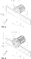
- a linear drive 1 according to the invention is shown in a perspective plan view.
- This linear drive 1 essentially comprises at least one primary part 5, designed as a reaction rail 5a, with a return plate 5c, a secondary part 3, which is designed as at least one first magnetic wheel 3a, and a rotary drive 2, which is mechanically connected to the at least one first magnetic wheel 3a connected is.
- the at least one first magnetic wheel 3a is equipped with magnets 4 in such a way that these magnets 4 generate a magnetic field that penetrates the reaction rail 5a and induce a number of eddy currents I 8 in this reaction rail 5a, which interact with the magnetic field, whereby the magnetic field closes in a known manner via the return plate 5c of the primary part 5.
- the linear drive 1 is equipped with at least one second magnetic wheel 3b of the secondary part 3 in addition to the first magnetic wheel 3a, the first and the second magnetic wheel 3a, 3b being arranged parallel to one another on a common axis 15 of the rotary drive 2 , and wherein the first and the second magnetic wheel 3a, 3b are spaced apart on this axis 15 in such a way that the at least one first reaction rail 5 can be arranged in a magnetically operatively connected manner in between.
- the first and/or the second magnetic wheel 3a, 3b is/are fitted with magnets 4 in such a way that these magnets 4 generate the magnetic field B 6 between this first and this second magnetic wheel 3a, 3b, which magnetic field B 6 also penetrates the reaction rail 5a and thereby with it interacts.
- 1c additionally shows possible arrangements of the magnets 4 on the first and the second magnetic wheel 3a, 3b.
- the secondary part is 3 in 1c shown in a plan view of the first magnetic wheel 3a and the second magnetic wheel 3b, with the magnets 4a being designed as permanent magnets 4a on one of the two and as electromagnets 4b on the other, optionally with a respective ferrite core 4c.
- FIG. 1b respectively adjacent magnets 4 on the respective first or second magnetic wheel 3a, 3b, have a different polarity and also opposing magnets 4 on the one hand on the first magnetic wheel 3a and on the other hand on the second magnetic wheel 3b, provided that both have magnets 4 are equipped as in the Figures 2a to 2c shown as an example.
- the magnetic field B 6 is shown using an example, which magnetic field B 6 is generated between the first and the second wheel 3a, 3b by the two associated magnets 4 with the polarities "N" and "S".
- the rotary drive 2 sets the secondary part 3 in a rotating motion with the direction of rotation 7b, whereby the magnets 4 are periodically moved into the region of the reaction rail 5a screw in and out again.
- the secondary part 3 of the linear drive 1 according to the invention with the rotary drive 2 is arranged on a support frame 11 of a drive platform 10 of a vehicle not shown in detail here, with a power supply 12, 12b of the linear drive 1 being connected via a number of current collectors 16 on busbars 9 the drive platform 10 can take place.
- Further examples of energy supplies 12a or 12c are also symbolically indicated here, a more detailed explanation of which does not appear necessary in view of specialist knowledge.
- the primary part 5 or the secondary part 3 it is optionally possible to design the primary part 5 or the secondary part 3 to be stationary and the other part to be movable.
- Figures 4a and 4b show two further embodiments of the linear drive 1 according to the invention, their difference to those described above Linear actuators 1 can be seen essentially in the horizontal arrangement of the secondary part 3 and the first and second magnetic wheel 3a, 3b.
- one leg of an L-profile support 14a serves as a reaction rail and in Figure 4b a leg of an H-profile beam 14b.
- Fig. 1a discussed functionality for the translatory drive in the direction of force F 7a, see also Fig.
- the Figure 4c showed a further advantageous embodiment of the invention, in which, compared to the embodiment in Figure 4b , a further, parallel to the first reaction rail 5a, second reaction rail 5b is shown, which is operatively connected to a further magnetic wheel 3c.
Landscapes
- Engineering & Computer Science (AREA)
- Power Engineering (AREA)
- Physics & Mathematics (AREA)
- Electromagnetism (AREA)
- Transportation (AREA)
- Mechanical Engineering (AREA)
- Linear Motors (AREA)
- Dynamo-Electric Clutches, Dynamo-Electric Brakes (AREA)
Priority Applications (4)
| Application Number | Priority Date | Filing Date | Title |
|---|---|---|---|
| EP21171873.9A EP4087103A1 (fr) | 2021-05-03 | 2021-05-03 | Entraînement linéaire |
| PCT/EP2022/061769 WO2022233822A1 (fr) | 2021-05-03 | 2022-05-03 | Entraînement linéaire |
| CA3215140A CA3215140A1 (fr) | 2021-05-03 | 2022-05-03 | Entrainement lineaire |
| CN202280032184.2A CN117242683A (zh) | 2021-05-03 | 2022-05-03 | 线性驱动器 |
Applications Claiming Priority (1)
| Application Number | Priority Date | Filing Date | Title |
|---|---|---|---|
| EP21171873.9A EP4087103A1 (fr) | 2021-05-03 | 2021-05-03 | Entraînement linéaire |
Publications (1)
| Publication Number | Publication Date |
|---|---|
| EP4087103A1 true EP4087103A1 (fr) | 2022-11-09 |
Family
ID=75787008
Family Applications (1)
| Application Number | Title | Priority Date | Filing Date |
|---|---|---|---|
| EP21171873.9A Pending EP4087103A1 (fr) | 2021-05-03 | 2021-05-03 | Entraînement linéaire |
Country Status (4)
| Country | Link |
|---|---|
| EP (1) | EP4087103A1 (fr) |
| CN (1) | CN117242683A (fr) |
| CA (1) | CA3215140A1 (fr) |
| WO (1) | WO2022233822A1 (fr) |
Citations (6)
| Publication number | Priority date | Publication date | Assignee | Title |
|---|---|---|---|---|
| JPH05336616A (ja) * | 1991-11-22 | 1993-12-17 | Aqueous Res:Kk | 車両用駆動装置及び二元推進式車両 |
| JPH09261805A (ja) * | 1996-03-19 | 1997-10-03 | Yaskawa Electric Corp | 磁気浮上アクチュエータ |
| US20030205163A1 (en) * | 2001-07-02 | 2003-11-06 | Magna Force, Inc. | Apparatus, systems and methods for levitating and moving objects |
| WO2015191935A1 (fr) * | 2014-06-11 | 2015-12-17 | Arx Pax, LLC | Propulsion et commande pour un véhicule à sustentation magnétique |
| EP3107195A1 (fr) | 2015-06-16 | 2016-12-21 | InDriveTec AG | Système d'entraînement de moteur linéaire |
| EP2269289B1 (fr) * | 2008-04-16 | 2019-11-27 | SEW-EURODRIVE GmbH & Co. KG | Dispositif de transport |
-
2021
- 2021-05-03 EP EP21171873.9A patent/EP4087103A1/fr active Pending
-
2022
- 2022-05-03 CN CN202280032184.2A patent/CN117242683A/zh active Pending
- 2022-05-03 CA CA3215140A patent/CA3215140A1/fr active Pending
- 2022-05-03 WO PCT/EP2022/061769 patent/WO2022233822A1/fr active Application Filing
Patent Citations (6)
| Publication number | Priority date | Publication date | Assignee | Title |
|---|---|---|---|---|
| JPH05336616A (ja) * | 1991-11-22 | 1993-12-17 | Aqueous Res:Kk | 車両用駆動装置及び二元推進式車両 |
| JPH09261805A (ja) * | 1996-03-19 | 1997-10-03 | Yaskawa Electric Corp | 磁気浮上アクチュエータ |
| US20030205163A1 (en) * | 2001-07-02 | 2003-11-06 | Magna Force, Inc. | Apparatus, systems and methods for levitating and moving objects |
| EP2269289B1 (fr) * | 2008-04-16 | 2019-11-27 | SEW-EURODRIVE GmbH & Co. KG | Dispositif de transport |
| WO2015191935A1 (fr) * | 2014-06-11 | 2015-12-17 | Arx Pax, LLC | Propulsion et commande pour un véhicule à sustentation magnétique |
| EP3107195A1 (fr) | 2015-06-16 | 2016-12-21 | InDriveTec AG | Système d'entraînement de moteur linéaire |
Also Published As
| Publication number | Publication date |
|---|---|
| CA3215140A1 (fr) | 2022-11-10 |
| CN117242683A (zh) | 2023-12-15 |
| WO2022233822A1 (fr) | 2022-11-10 |
Similar Documents
| Publication | Publication Date | Title |
|---|---|---|
| EP2150434B1 (fr) | Véhicule équipé d'un frein à courants de foucault pour un système de transport guidé et système de transport, en particulier train à sustentation magnétique, fonctionnant avec ledit véhicule | |
| EP2219900B1 (fr) | Train à sustentation magnétique | |
| EP2099640B1 (fr) | Véhicule à sustentation magnétique comprenant au moins un système magnétique | |
| EP0986490B1 (fr) | Systeme de deplacement pour vehicule a sustentation magnetique | |
| EP1725418A1 (fr) | Voie pour train a sustentation magnetique a frein a courants de foucault | |
| EP1851408A1 (fr) | Porte coulissante comprenant un systeme d'entrainement magnetique et un systeme de mesure de la trajectoire | |
| DE4222167C2 (de) | Magnetschwebebahn mit Supraleitung sowie dafür vorgesehene Stromzuleitungseinrichtung | |
| DE2438889A1 (de) | Fahrzeug mit linearsynchronmotor | |
| EP3489072B1 (fr) | Trajet de transport d'un moteur linéaire à stator long | |
| DE2541599A1 (de) | Integrierte magnetfahrtechnik fuer den nahverkehr | |
| DE2710156A1 (de) | Permanent-magnetanordnungen fuer tragen, fuehren und vortrieb - geregelte permanentmagnete mit geringer stelleistung | |
| DE2339060C3 (de) | Magnetische Trag- und Vortriebseinrichtung fUr ein längs eines Fahrweges bewegbares Fahrzeug | |
| DE1206010B (de) | Anordnung fuer ein Zugsystem | |
| DE19718840C1 (de) | Antriebsmittel für eine Linearbewegung, insbesondere kontinuierliche Linearbewegung und Langstator-Linearmotor | |
| EP4087103A1 (fr) | Entraînement linéaire | |
| DE2329718A1 (de) | Linearmotor fuer hochgeschwindigkeitsbahn | |
| EP1647655B1 (fr) | Porte coulissante avec système d'entraînement avec réseau magnétique | |
| DE102011011810A1 (de) | Elektromagnetische Schwebetechnik mit einfachem Fahrweg | |
| DE102009025337B4 (de) | Tragmagnet mit Permanentmagneten und Stromstellung | |
| DE102006021041A1 (de) | Magnetantriebsmotor mit einer bipolaren Rotorscheibe | |
| DE3909705A1 (de) | Unterteilte speiseschaltung fuer eine magnetschwebebahn mit supraleitung | |
| DE2425940C2 (fr) | ||
| DE102004050328B3 (de) | Schiebetür mit einem magnetischen Antriebssystem mit einer Magnetreihe | |
| DE1563970B2 (de) | Gleisfahrzeug mit elektrischem antrieb durch zumindest einen linearen induktions motor | |
| DE102004050343B3 (de) | Schiebetür mit einem magnetischen Antriebssystem mit einer Magnetreihe |
Legal Events
| Date | Code | Title | Description |
|---|---|---|---|
| STAA | Information on the status of an ep patent application or granted ep patent |
Free format text: STATUS: EXAMINATION IS IN PROGRESS |
|
| PUAI | Public reference made under article 153(3) epc to a published international application that has entered the european phase |
Free format text: ORIGINAL CODE: 0009012 |
|
| 17P | Request for examination filed |
Effective date: 20210503 |
|
| AK | Designated contracting states |
Kind code of ref document: A1 Designated state(s): AL AT BE BG CH CY CZ DE DK EE ES FI FR GB GR HR HU IE IS IT LI LT LU LV MC MK MT NL NO PL PT RO RS SE SI SK SM TR |
|
| RBV | Designated contracting states (corrected) |
Designated state(s): AL AT BE BG CH CY CZ DE DK EE ES FI FR GB GR HR HU IE IS IT LI LT LU LV MC MK MT NL NO PL PT RO RS SE SI SK SM TR |
|
| RIN1 | Information on inventor provided before grant (corrected) |
Inventor name: VINZENS, MARTIN Inventor name: JULEN, ERIC |