EP1647655B1 - Porte coulissante avec système d'entraînement avec réseau magnétique - Google Patents
Porte coulissante avec système d'entraînement avec réseau magnétique Download PDFInfo
- Publication number
- EP1647655B1 EP1647655B1 EP20050019301 EP05019301A EP1647655B1 EP 1647655 B1 EP1647655 B1 EP 1647655B1 EP 20050019301 EP20050019301 EP 20050019301 EP 05019301 A EP05019301 A EP 05019301A EP 1647655 B1 EP1647655 B1 EP 1647655B1
- Authority
- EP
- European Patent Office
- Prior art keywords
- coil
- magnets
- magnetic
- sliding door
- phase
- Prior art date
- Legal status (The legal status is an assumption and is not a legal conclusion. Google has not performed a legal analysis and makes no representation as to the accuracy of the status listed.)
- Active
Links
Images


Classifications
-
- H—ELECTRICITY
- H02—GENERATION; CONVERSION OR DISTRIBUTION OF ELECTRIC POWER
- H02K—DYNAMO-ELECTRIC MACHINES
- H02K41/00—Propulsion systems in which a rigid body is moved along a path due to dynamo-electric interaction between the body and a magnetic field travelling along the path
- H02K41/02—Linear motors; Sectional motors
- H02K41/03—Synchronous motors; Motors moving step by step; Reluctance motors
- H02K41/031—Synchronous motors; Motors moving step by step; Reluctance motors of the permanent magnet type
-
- E—FIXED CONSTRUCTIONS
- E05—LOCKS; KEYS; WINDOW OR DOOR FITTINGS; SAFES
- E05D—HINGES OR SUSPENSION DEVICES FOR DOORS, WINDOWS OR WINGS
- E05D15/00—Suspension arrangements for wings
- E05D15/06—Suspension arrangements for wings for wings sliding horizontally more or less in their own plane
- E05D15/0621—Details, e.g. suspension or supporting guides
- E05D15/0626—Details, e.g. suspension or supporting guides for wings suspended at the top
-
- E—FIXED CONSTRUCTIONS
- E05—LOCKS; KEYS; WINDOW OR DOOR FITTINGS; SAFES
- E05F—DEVICES FOR MOVING WINGS INTO OPEN OR CLOSED POSITION; CHECKS FOR WINGS; WING FITTINGS NOT OTHERWISE PROVIDED FOR, CONCERNED WITH THE FUNCTIONING OF THE WING
- E05F15/00—Power-operated mechanisms for wings
- E05F15/60—Power-operated mechanisms for wings using electrical actuators
-
- E—FIXED CONSTRUCTIONS
- E05—LOCKS; KEYS; WINDOW OR DOOR FITTINGS; SAFES
- E05Y—INDEXING SCHEME RELATING TO HINGES OR OTHER SUSPENSION DEVICES FOR DOORS, WINDOWS OR WINGS AND DEVICES FOR MOVING WINGS INTO OPEN OR CLOSED POSITION, CHECKS FOR WINGS AND WING FITTINGS NOT OTHERWISE PROVIDED FOR, CONCERNED WITH THE FUNCTIONING OF THE WING
- E05Y2900/00—Application of doors, windows, wings or fittings thereof
- E05Y2900/10—Application of doors, windows, wings or fittings thereof for buildings or parts thereof
- E05Y2900/13—Application of doors, windows, wings or fittings thereof for buildings or parts thereof characterised by the type of wing
- E05Y2900/132—Doors
-
- H—ELECTRICITY
- H02—GENERATION; CONVERSION OR DISTRIBUTION OF ELECTRIC POWER
- H02K—DYNAMO-ELECTRIC MACHINES
- H02K1/00—Details of the magnetic circuit
- H02K1/06—Details of the magnetic circuit characterised by the shape, form or construction
- H02K1/22—Rotating parts of the magnetic circuit
- H02K1/27—Rotor cores with permanent magnets
- H02K1/2706—Inner rotors
- H02K1/272—Inner rotors the magnetisation axis of the magnets being perpendicular to the rotor axis
- H02K1/274—Inner rotors the magnetisation axis of the magnets being perpendicular to the rotor axis the rotor consisting of two or more circumferentially positioned magnets
- H02K1/2753—Inner rotors the magnetisation axis of the magnets being perpendicular to the rotor axis the rotor consisting of two or more circumferentially positioned magnets the rotor consisting of magnets or groups of magnets arranged with alternating polarity
- H02K1/276—Magnets embedded in the magnetic core, e.g. interior permanent magnets [IPM]
-
- H—ELECTRICITY
- H02—GENERATION; CONVERSION OR DISTRIBUTION OF ELECTRIC POWER
- H02K—DYNAMO-ELECTRIC MACHINES
- H02K16/00—Machines with more than one rotor or stator
-
- H—ELECTRICITY
- H02—GENERATION; CONVERSION OR DISTRIBUTION OF ELECTRIC POWER
- H02K—DYNAMO-ELECTRIC MACHINES
- H02K2213/00—Specific aspects, not otherwise provided for and not covered by codes H02K2201/00 - H02K2211/00
- H02K2213/12—Machines characterised by the modularity of some components
-
- H—ELECTRICITY
- H02—GENERATION; CONVERSION OR DISTRIBUTION OF ELECTRIC POWER
- H02K—DYNAMO-ELECTRIC MACHINES
- H02K3/00—Details of windings
- H02K3/04—Windings characterised by the conductor shape, form or construction, e.g. with bar conductors
- H02K3/18—Windings for salient poles
-
- H—ELECTRICITY
- H02—GENERATION; CONVERSION OR DISTRIBUTION OF ELECTRIC POWER
- H02K—DYNAMO-ELECTRIC MACHINES
- H02K3/00—Details of windings
- H02K3/04—Windings characterised by the conductor shape, form or construction, e.g. with bar conductors
- H02K3/28—Layout of windings or of connections between windings
-
- H—ELECTRICITY
- H02—GENERATION; CONVERSION OR DISTRIBUTION OF ELECTRIC POWER
- H02K—DYNAMO-ELECTRIC MACHINES
- H02K7/00—Arrangements for handling mechanical energy structurally associated with dynamo-electric machines, e.g. structural association with mechanical driving motors or auxiliary dynamo-electric machines
- H02K7/08—Structural association with bearings
- H02K7/09—Structural association with bearings with magnetic bearings
-
- H—ELECTRICITY
- H02—GENERATION; CONVERSION OR DISTRIBUTION OF ELECTRIC POWER
- H02N—ELECTRIC MACHINES NOT OTHERWISE PROVIDED FOR
- H02N15/00—Holding or levitation devices using magnetic attraction or repulsion, not otherwise provided for
Definitions
- the invention relates to a sliding door with a magnetic drive system for at least one door leaf, with a linear drive unit with at least one row of magnets.
- the term magnet series also includes elongated individual magnets.
- the magnet series can be arranged stationary or mobile.
- a sliding door guide is known in the cooperating magnets under normal load effect a non-contact floating guide held in a sliding guide door or the like, wherein in addition to the stationary magnet arranged the sliding guide a stator of a linear motor is arranged, the rotor is arranged on the sliding door.
- the selected V-shaped arrangement of the permanent magnets of the disclosed permanently excited magnetic support means no laterally stable guideway can be realized, which is why a relatively complicated arrangement and design of the stator and rotor is required. This arrangement increases the cost of such a sliding door enormously.
- a combined storage and drive system for an automatically operated door in which a permanently energized magnetic support system is symmetrical and has stationary and movable magnet rows, each arranged in a plane, wherein the support system is in a labile equilibrium and at the support system has symmetrically arranged lateral guide elements, which can be stored in a roll shape. Due to the thus achieved laterally stable track results in a simple design and arrangement of the stator and rotor housed in a common housing linear motor, namely the ability to arbitrarily arrange stator and rotor of the linear motor with respect to the support system and with respect to the shape of stand and runners not to be limited by the support system.
- an electromagnetic drive system for magnetic levitation and support systems in which a stable levitation and support state is achieved by a suitable arrangement of permanent magnet and ferromagnetic material.
- the permanent magnet puts the ferromagnetic material in the state of a magnetic partial saturation.
- Electromagnets are arranged so that the permanent magnets are moved solely by a change in saturation in the support rail and the coil cores are included in the permanent magnetic partial saturation, which leads to the floating and wearing state.
- FIG. 1 shows the WO 94/13055 a stand drive for a linear electric drive and a door provided with such a stand, which is suspended by means of magnets in the lintel of a frame.
- a plurality of magnets or magnet groups are arranged on the door panel whose magnetic field strength is so great that an attraction force is achieved to a guide plate, which is arranged on the underside of the lintel, wherein the attraction force is sufficient to lift the weight of the door panel.
- the sliding door according to the invention with a magnetic drive system for at least one door, with a linear drive unit, the at least one arranged in the drive direction magnetic series, the magnetization in their longitudinal direction at certain intervals before the sign changes and at least one coil arrangement which, with appropriate control, an interaction with the least effecting a series of magnets which induces feed forces, the coil arrangement having a number of coil cores, of which only every other one is provided with a coil winding, has the advantage over the prior art that the manufacturing costs are reduced by providing coil windings on only every second coil Spool core can be significantly reduced, the properties of the drive system with respect to its latching forces are not changed, since the coil cores are still provided. Furthermore, all the drive phases are retained by the expansion of the at least one magnet row, in particular in the case of a three-phase system.
- the coil arrangement is preferably controlled in three phases, so that all drive phases are maintained.
- a coil winding substantially fills the space between two coil cores.
- the at least one magnetic row preferably consists of one or more high-performance magnets, preferably rare-earth high-performance magnets, more preferably neodymium-iron-boron (NeFeB) or samarium-cobalt (Sm 2 Co) or plastic-bonded magnet materials.
- high-performance magnets preferably rare-earth high-performance magnets, more preferably neodymium-iron-boron (NeFeB) or samarium-cobalt (Sm 2 Co) or plastic-bonded magnet materials.
- the drive system according to the invention or combined support and drive system is used to drive at least one door leaf of a sliding door, which is preferably designed as a curved sliding door or horizontal sliding wall. In addition to this insert, it can also be used to drive gate leaves or in feed devices, handling devices or transport systems.
- FIG. 1 shows a schematic diagram of a first preferred embodiment of the invention preferably used magnetic support device in cross section.
- a coordinate system is shown, in which an x-direction represents a direction of travel of a door leaf 5 suspended from the carrying device according to the invention.
- the direction of the forces acting on the magnetic support transverse forces is the y-direction and the conditional by the weight of the suspended door leaf 5 vertical downward magnetic deflection is located in the z-direction.
- a fixed to a support carriage 4 series of magnets 1 is positively guided by a provided on the support carriage 4 mechanical whilsetement 3, which cooperates with a housing 6 of the support centered in the horizontal direction between soft magnetic support rails 2a, 2b, which form the support member 2, while they in the vertical direction and in the direction of travel (x) of the door leaf 5 is freely displaceable.
- the transverse forces acting on the magnets 1 a, 1 b, 1 c, 1 d in the y direction largely cancel each other out.
- In the vertical direction (z-direction) take the magnets 1a, 1b, 1c, 1d only in the load-free state, ie without attached to the support carriage 4 load, as in FIG. 1a ) shown a symmetrical position.
- the cause of this restoring force are the between the magnets 1a, 1b, 1c, 1d of the magnetic row 1 and the support rails 2a, 2b acting magnetic attraction forces, with only the part of the magnets 1 a, 1 b, 1 c, 1 d, between the Support rails 2a, 2b emerges downwards, contributes to this magnetic load capacity. As this part increases with increasing vertical deflection, the magnetic load increases in magnitude continuously with the deflection.
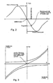
- FIG. 2 shows the dependence between the vertical deflection of the magnetic series 1 and the magnetic load capacity in a characteristic, ie the load capacity curve of the support device according to the in FIG. 1 shown embodiment.
- a characteristic ie the load capacity curve of the support device according to the in FIG. 1 shown embodiment.
- On the abscissa is the vertical deflection z down, z. B. in mm and on the ordinate the corresponding generated magnetic load F (z), z. In Newton.
- the course of the load capacity curve is characterized by an upper and a lower break-off point, which are each achieved when the magnets between the support rails upwards and downwards completely emerge, as is the case in the down in Figure 1e ) is shown.
- the housing 6 accommodating the mounting rails 2a, 2b and providing a horizontal guide for the guide element 3 simultaneously comprises two projections 6a, 6b respectively arranged at its lower ends, which mechanically limit the possible deflection of the support carriage 4 and thus rigidly fastened thereto Magnet row 1 in the z direction are.
- FIG. 3 shows for a gap width of z. B. -1 mm to +1 mm, a transverse force profile F (y) in response to a lateral displacement y of the magnets 1a, 1b, 1c, 1d, which has a positive slope over the entire course.
- the guide element 3 Since there is only an unstable equilibrium of forces in the middle position, the guide element 3 must provide a precise mechanical support, which the magnetic row 1 during the travel movement of the magnetic row 1 in the direction of movement, d. H. in the x-direction, exactly centered between the support rails 2a, 2b leads. The more precisely this centering can be realized, the lower the resulting transverse force F (y) and associated friction forces of the mechanical bearing.
- the magnet width ie the dimensions of the magnet row 1 or of its individual magnets 1a, 1b, 1c, 1d in the y direction
- the height of the magnet should be as small as possible, because small magnet heights increase the rigidity of the load-bearing field by bundling the field.
- the height of the mounting rails 2a, 2b should be as small as possible, a mounting rail height is less than 1/2 of the magnet height, because the field lines of the permanent magnets are bundled and thereby increases the rigidity of the magnetic support system.
- the arrangement should be chosen so that the soft magnetic support rails 2a, 2b in the state of equilibrium, in which the magnetic load F (z) is equal to the amount caused by loading the magnetic row 1 with the door leaf 5 weight force F g , vertically asymmetrical about the row of magnets 1 lie and the row of magnets 1 should be as continuous as possible in order to avoid latching forces in the direction of movement, ie in the x-direction.
- FIG. 4 is a sectional view of a supervision of in FIG. 1a shown according to a section line AA carrying device according to the first preferred embodiment of the invention.
- the magnet array 1 consists of individual magnets 1a, 1b, 1c, 1d, which are arranged with alternating magnetization direction between the two laterally arranged mounting rails 2a, 2b, which consist of a soft magnetic material.
- the individual magnets 1a, 1b, 1c, 1d are attached to the movable support carriage 4 to form the magnet array 1 and can be placed between the rails 2a, 2b in x - and z-direction to be moved.
- FIG. 5 shows two drive segments of a first preferred embodiment of the invention preferably used drive system, here as a combined magnetic support and drive system, in a sectional plan view in which the magnetic linear drive used in the invention acts on the rows of magnets 1e, 1f, attached to a support carriage 4, not shown are.
- the two rows of magnets 1e, 1f each have alternately polarized individual magnets, wherein the polarities of the transversely offset individual magnets of the two rows of magnets are rectified.
- Coils 7 are arranged between the magnet rows 1e, 1f such that a respective coil core 12 extends in the transverse direction, ie y-direction. On the side facing away from the coils 7 with coil cores 12 of the magnetic row 1 is in each case a side region of the support rail 2d.
- stator coils 7 are arranged with their respective coil cores 12 in different relative positions to the grid of the permanent magnets 1, 1e, 1f.
- each relative position is assigned to an electrical phase of a drive system required for the linear drive, as few electrical phases as possible should be used. Due to the available three-phase three-phase network is a Three-phase system, as exemplified in FIG. 6 shown is very inexpensive to build.
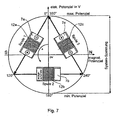
- FIG. 6 shows the interconnection of the coils of FIG. 5
- a first coil 7a with a first coil core 12a is connected between a first phase and a second phase of a three-phase three-phase system whose three phases are evenly distributed, ie the second phase at 120 ° and a third phase at 240 °, when the first phase is at 0 °.
- FIG. 7 Such a circular phase diagram with drawn coils is shown in FIG FIG. 7 shown.
- the electric potential is given in V and on the abscissa the magnetic potential.
- phase pass of 180 ° corresponds to a displacement of the rotor by the distance between the centers of two adjacent magnets, ie the magnetic grid R M. Due to the alternating polarization of the magnets in the rotor, a pole change is carried out when shifting around the magnetic grid R M. After a 360 ° phase pass, the rotor displacement is two R M. In this case, the magnets are again in the starting position relative to the grid R S of the stator coils, comparable to a 360 ° rotation of the rotor of a two-pole DC motor.
- the ordinate is considered, on which the applied electrical voltage potential is shown.
- the maximum potential at 180 °, the minimum potential and at 90 ° or 270 °, an average voltage potential.
- the coils are represented in the diagram by arrows whose start and end points represent the contacts.
- the respectively applied coil voltage can be read off by projection of start and end point of the arrows on the potential axis. By the direction of the arrow, the current direction and thereby the magnetization direction of the coil is set.
- phase diagram instead of a continuous sinusoidal voltage source, the phase diagram according to FIG. 7
- a controller with a rectangular characteristic can also be used.
- the rectangular characteristic is represented by fish shells.
- the phase connections can each assume the three states plus potential, minus potential and potential-free.
- the plus potential z. B. in a range between 300 ° and 60 ° and the negative potential in a range of 120 ° to 240 ° and the ranges between 60 ° and 120 ° and 240 ° and 300 ° represent the potential-free state in which the coils are not are connected.
- the more uneven thrust compared to sinusoidal control is disadvantageous.
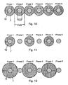
- FIG. 10 shows an arrangement of a coil assembly in a sliding door according to the prior art.
- individual coils 7 are provided on each coil core 12 of the coil arrangement.
- FIG. 11 shows an exemplary arrangement of a coil assembly in a sliding door.
- each second coil core 12 of the coil arrangement individual coils 7 are provided.
- the FIG. 12 shows an arrangement of a coil assembly in a sliding door according to a preferred embodiment of the invention.
- D Kem diameter of the coil cores
- the existing according to the first preferred embodiment disadvantage that there in comparison with the in FIG. 10 shown arrangement according to the prior art, only half the coil cross-sectional area is flooded, does not exist here, since the flooded coil cross-sectional area with the in FIG. 10 the arrangement shown in the prior art is the same, resulting in the same shear forces.
- the sliding door according to the invention with the magnetic drive system according to the invention can also be designed so that the only preferably magnetically mounted support means is provided separately from the drive system according to the invention.
Claims (4)
- Porte coulissante avec un système d'entraînement magnétique pour au moins un vantail de porte (5), avec un entraînement linéaire, lequel présente• au moins une rangée d'aimants (1, 1e, 1f) agencée en la direction d'entraînement, dont la magnétisation change de signe à certaines intervalles en sa direction longitudinale, et• au moins un agencement de bobines, qui, par une activation appropriée, provoque une interaction avec ladite au moins une range d'aimants (1; 1e; 1f) causant des forces d'avance,caractérisée en ce que• l'agencement de bobines présente un nombre de noyaux de bobines (12) dont seulement un sur deux est pourvu d'un enroulement à bobinage (7), et• les noyaux de bobine (12) présentent un diamètre Dnoyau et les bobines individuelles (7) présentent un diamètre Dbobine = 3*Dnoyau, la distance entre deux noyaux de bobines correspondant environ à Dnoyau.
- Porte coulissante selon la revendication 1, caractérisée en ce que l'agencement de bobine est à contrôle tri-phases.
- Porte coulissante selon la revendication 1 ou 2, caractérisée en ce que ladite au moins une rangée d'aimants (1, 1e, 1f) consiste en un ou plusieurs aimants à haute puissance, de préférence d'aimant à haute puissance de terres rares, et encore plus préféré du type NeFeB ou Sm2Co.
- Porte coulissante selon l'une des revendications précédentes, caractérisée en ce que la porte coulissante est aménagée comme porte coulissante en arc ou paroi coulissante horizontal.
Applications Claiming Priority (1)
| Application Number | Priority Date | Filing Date | Title |
|---|---|---|---|
| DE200410050337 DE102004050337B3 (de) | 2004-10-17 | 2004-10-17 | Schiebetür mit einem Antriebssystem mit einer Magnetreihe |
Publications (3)
| Publication Number | Publication Date |
|---|---|
| EP1647655A2 EP1647655A2 (fr) | 2006-04-19 |
| EP1647655A3 EP1647655A3 (fr) | 2010-08-18 |
| EP1647655B1 true EP1647655B1 (fr) | 2014-12-24 |
Family
ID=35502709
Family Applications (1)
| Application Number | Title | Priority Date | Filing Date |
|---|---|---|---|
| EP20050019301 Active EP1647655B1 (fr) | 2004-10-17 | 2005-09-06 | Porte coulissante avec système d'entraînement avec réseau magnétique |
Country Status (3)
| Country | Link |
|---|---|
| EP (1) | EP1647655B1 (fr) |
| DE (1) | DE102004050337B3 (fr) |
| ES (1) | ES2533454T3 (fr) |
Families Citing this family (4)
| Publication number | Priority date | Publication date | Assignee | Title |
|---|---|---|---|---|
| DE102012204917A1 (de) | 2012-03-27 | 2013-10-02 | Beckhoff Automation Gmbh | Positionserfassungsvorrichtung und Verfahren zum Erfassen einer Position eines beweglichen Elements einer Antriebsvorrichtung |
| DE102012204916A1 (de) | 2012-03-27 | 2013-10-02 | Beckhoff Automation Gmbh | Statorvorrichtung für einen Linearmotor und lineares Transportsystem |
| DE102012204919A1 (de) | 2012-03-27 | 2013-10-02 | Beckhoff Automation Gmbh | Statorvorrichtung für einen linearmotor und lineares transportsystem |
| CN105041095B (zh) * | 2015-03-10 | 2017-03-15 | 中北大学 | 磁悬浮自驱平开自动门 |
Family Cites Families (10)
| Publication number | Priority date | Publication date | Assignee | Title |
|---|---|---|---|---|
| DE4016948A1 (de) * | 1990-05-25 | 1991-11-28 | Geze Gmbh & Co | Schiebefuehrung |
| DE4111853A1 (de) * | 1991-04-11 | 1992-10-15 | Intrasys Gmbh | Vorrichtung zur begrenzung der hoechstgeschwindigkeit eines elektromotors |
| NL9202053A (nl) | 1992-11-26 | 1994-06-16 | Stator B V | Statorelement voor een lineaire elektrische aandrijving, deur voorzien van een dergelijk statorelement. |
| DE19547686A1 (de) * | 1995-12-20 | 1997-06-26 | Indramat Gmbh | Elektrischer Synchron-Linearmotor und Verfahren zur Ermittlung des Kommutierungsoffsets eines Linearantriebs mit einem solchen elektrischen Synchron-Linearmotor |
| DE19618518C1 (de) * | 1996-05-08 | 1998-03-05 | Schuster Heinz Peter | Elektromagnetisches Antriebssystem für magnetische Schwebe- und Tragesysteme |
| DE19725525A1 (de) * | 1997-06-17 | 1998-12-24 | Bosch Gmbh Robert | Elektronisch kommutierter Motor |
| DE19908349A1 (de) * | 1999-02-26 | 2000-08-31 | Elektrische Automatisierungs U | Kombiniertes Schwebe-Antriebssystem |
| DE10257583B3 (de) * | 2002-12-09 | 2004-09-09 | Dorma Gmbh + Co. Kg | Schiebetür oder dergleichen |
| DE10392674T5 (de) * | 2003-04-11 | 2005-07-07 | Mitsubishi Denki K.K. | Linearmotor |
| JP3872055B2 (ja) * | 2003-06-20 | 2007-01-24 | 三菱電機株式会社 | リニアモータの電機子 |
-
2004
- 2004-10-17 DE DE200410050337 patent/DE102004050337B3/de not_active Expired - Fee Related
-
2005
- 2005-09-06 EP EP20050019301 patent/EP1647655B1/fr active Active
- 2005-09-06 ES ES05019301.0T patent/ES2533454T3/es active Active
Also Published As
| Publication number | Publication date |
|---|---|
| ES2533454T3 (es) | 2015-04-10 |
| EP1647655A3 (fr) | 2010-08-18 |
| DE102004050337B3 (de) | 2006-02-02 |
| EP1647655A2 (fr) | 2006-04-19 |
Similar Documents
| Publication | Publication Date | Title |
|---|---|---|
| EP1805386A1 (fr) | Porte coulissante comprenant un systeme de support et/ou d'entrainement magnetique presentant une rangee d'aimants | |
| EP1805385B1 (fr) | Porte coulissante pourvue d'un systeme d'entrainement comprenant une serie d'aimants | |
| EP1647655B1 (fr) | Porte coulissante avec système d'entraînement avec réseau magnétique | |
| EP1681425A2 (fr) | Porte coulissante montée sur rouleaux et avec un système d'entraînement magnétique | |
| EP1805384B1 (fr) | Porte coulissante a systeme de suspension et d'entrainement magnetique | |
| DE102005002038B4 (de) | Schiebetür mit einem magnetischen Antriebssystem mit einem Linearmotor-Stator | |
| EP1647656A2 (fr) | Porte coulissante avec mécanisme de support monté sur rouleaux | |
| EP1805878B1 (fr) | Porte coulissante entraînée par un moteur linéaire | |
| DE102004050342B4 (de) | Schiebetür mit einem kombinierten magnetischen Trag- und Antriebssystem mit einer Magnetreihe | |
| DE102004050328B3 (de) | Schiebetür mit einem magnetischen Antriebssystem mit einer Magnetreihe | |
| DE102004050313A1 (de) | Schiebetür mit einem Antriebssystem mit einer Magnetreihe | |
| DE102004050327B3 (de) | Teleskopschiebetür mit einem Linearmotor-Antrieb | |
| DE102004050338B4 (de) | Schiebetür mit einem magnetischen Trag- und Antriebssystem mit einer Magnetreihe | |
| DE102004050343B3 (de) | Schiebetür mit einem magnetischen Antriebssystem mit einer Magnetreihe | |
| DE102004050341B4 (de) | Schiebetürsystem mit einem magnetischen Trag- und Anttriebssystem mit einer Magnetreihe sowie eine Schiebetür mit einem solchen System | |
| DE102004050321A1 (de) | Schiebetür mit einem magnetischen Antriebssystem | |
| EP1805387B1 (fr) | Porte coulissante à entrainement à moteur linéaire | |
| DE102005002037B4 (de) | Rollengelagerte Schiebetür mit einem magnetischen Trag- und Antriebssystem | |
| DE102004050324A1 (de) | Schiebetür mit einem kombinierten magnetischen Trag- und Antriebssystem | |
| DE102004050331A1 (de) | Schiebetür mit einem Linearmotor-Antrieb | |
| DE202004020969U1 (de) | Schiebetür mit einem magnetischen Trag- und Antriebssystem | |
| DE102004050325A1 (de) | Schiebetür mit einem Antriebssystem mit einer Magnetreihe | |
| DE102004050319A1 (de) | Schiebetür mit einem kombinierten magnetischen Trag- und Antriebssystem mit einer Magnetreihe | |
| DE102004050330B4 (de) | Schiebetür mit einem kombinierten magnetischen Trag- und Antriebssystem mit mindestens einer Magnetreihe | |
| DE102004050318A1 (de) | Schiebetür mit einem Linearmotor-Antieb |
Legal Events
| Date | Code | Title | Description |
|---|---|---|---|
| PUAI | Public reference made under article 153(3) epc to a published international application that has entered the european phase |
Free format text: ORIGINAL CODE: 0009012 |
|
| AK | Designated contracting states |
Kind code of ref document: A2 Designated state(s): AT BE BG CH CY CZ DE DK EE ES FI FR GB GR HU IE IS IT LI LT LU LV MC NL PL PT RO SE SI SK TR |
|
| AX | Request for extension of the european patent |
Extension state: AL BA HR MK YU |
|
| PUAL | Search report despatched |
Free format text: ORIGINAL CODE: 0009013 |
|
| RAP1 | Party data changed (applicant data changed or rights of an application transferred) |
Owner name: DORMA GMBH + CO. KG |
|
| AK | Designated contracting states |
Kind code of ref document: A3 Designated state(s): AT BE BG CH CY CZ DE DK EE ES FI FR GB GR HU IE IS IT LI LT LU LV MC NL PL PT RO SE SI SK TR |
|
| AX | Request for extension of the european patent |
Extension state: AL BA HR MK YU |
|
| RIC1 | Information provided on ipc code assigned before grant |
Ipc: H02K 41/03 20060101ALI20100709BHEP Ipc: E05D 15/06 20060101AFI20060111BHEP Ipc: E05F 15/18 20060101ALI20100709BHEP |
|
| 17P | Request for examination filed |
Effective date: 20110218 |
|
| AKX | Designation fees paid |
Designated state(s): AT BE BG CH CY CZ DE DK EE ES FI FR GB GR HU IE IS IT LI LT LU LV MC NL PL PT RO SE SI SK TR |
|
| 17Q | First examination report despatched |
Effective date: 20110509 |
|
| REG | Reference to a national code |
Ref country code: DE Ref legal event code: R079 Ref document number: 502005014629 Country of ref document: DE Free format text: PREVIOUS MAIN CLASS: E05D0015060000 Ipc: H02K0015000000 |
|
| RIC1 | Information provided on ipc code assigned before grant |
Ipc: H02K 16/00 20060101ALI20140604BHEP Ipc: E05D 15/06 20060101ALI20140604BHEP Ipc: H02K 1/27 20060101ALI20140604BHEP Ipc: H02K 7/09 20060101ALI20140604BHEP Ipc: H02K 41/03 20060101ALI20140604BHEP Ipc: H02K 15/00 20060101AFI20140604BHEP Ipc: H02K 3/28 20060101ALI20140604BHEP Ipc: H02N 15/00 20060101ALI20140604BHEP Ipc: H02K 3/18 20060101ALI20140604BHEP Ipc: E05F 15/18 20060101ALI20140604BHEP |
|
| GRAP | Despatch of communication of intention to grant a patent |
Free format text: ORIGINAL CODE: EPIDOSNIGR1 |
|
| INTG | Intention to grant announced |
Effective date: 20140729 |
|
| GRAS | Grant fee paid |
Free format text: ORIGINAL CODE: EPIDOSNIGR3 |
|
| GRAA | (expected) grant |
Free format text: ORIGINAL CODE: 0009210 |
|
| STAA | Information on the status of an ep patent application or granted ep patent |
Free format text: STATUS: THE PATENT HAS BEEN GRANTED |
|
| AK | Designated contracting states |
Kind code of ref document: B1 Designated state(s): AT BE BG CH CY CZ DE DK EE ES FI FR GB GR HU IE IS IT LI LT LU LV MC NL PL PT RO SE SI SK TR |
|
| REG | Reference to a national code |
Ref country code: GB Ref legal event code: FG4D Free format text: NOT ENGLISH |
|
| REG | Reference to a national code |
Ref country code: CH Ref legal event code: EP |
|
| REG | Reference to a national code |
Ref country code: IE Ref legal event code: FG4D Free format text: LANGUAGE OF EP DOCUMENT: GERMAN |
|
| REG | Reference to a national code |
Ref country code: AT Ref legal event code: REF Ref document number: 703567 Country of ref document: AT Kind code of ref document: T Effective date: 20150115 |
|
| REG | Reference to a national code |
Ref country code: DE Ref legal event code: R079 Ref document number: 502005014629 Country of ref document: DE Free format text: PREVIOUS MAIN CLASS: H02K0015000000 Ipc: E05F0015600000 |
|
| REG | Reference to a national code |
Ref country code: DE Ref legal event code: R079 Ref document number: 502005014629 Country of ref document: DE Free format text: PREVIOUS MAIN CLASS: H02K0015000000 Ipc: E05F0015600000 Effective date: 20150119 Ref country code: DE Ref legal event code: R096 Ref document number: 502005014629 Country of ref document: DE Effective date: 20150226 Ref country code: DE Ref legal event code: R079 Ref document number: 502005014629 Country of ref document: DE Free format text: PREVIOUS MAIN CLASS: E05D0015060000 Ipc: H02K0015000000 Effective date: 20140604 |
|
| REG | Reference to a national code |
Ref country code: DE Ref legal event code: R081 Ref document number: 502005014629 Country of ref document: DE Owner name: DORMAKABA DEUTSCHLAND GMBH, DE Free format text: FORMER OWNER: DORMA GMBH & CO. KG, 58256 ENNEPETAL, DE Effective date: 20150224 Ref country code: DE Ref legal event code: R081 Ref document number: 502005014629 Country of ref document: DE Owner name: DORMAKABA DEUTSCHLAND GMBH, DE Free format text: FORMER OWNER: DORMA GMBH + CO. KG, 58256 ENNEPETAL, DE Effective date: 20150109 Ref country code: DE Ref legal event code: R081 Ref document number: 502005014629 Country of ref document: DE Owner name: DORMA DEUTSCHLAND GMBH, DE Free format text: FORMER OWNER: DORMA GMBH + CO. KG, 58256 ENNEPETAL, DE Effective date: 20150109 Ref country code: DE Ref legal event code: R081 Ref document number: 502005014629 Country of ref document: DE Owner name: DORMA DEUTSCHLAND GMBH, DE Free format text: FORMER OWNER: DORMA GMBH & CO. KG, 58256 ENNEPETAL, DE Effective date: 20150224 |
|
| RAP2 | Party data changed (patent owner data changed or rights of a patent transferred) |
Owner name: DORMA DEUTSCHLAND GMBH |
|
| REG | Reference to a national code |
Ref country code: ES Ref legal event code: FG2A Ref document number: 2533454 Country of ref document: ES Kind code of ref document: T3 Effective date: 20150410 |
|
| REG | Reference to a national code |
Ref country code: NL Ref legal event code: VDEP Effective date: 20141224 |
|
| PG25 | Lapsed in a contracting state [announced via postgrant information from national office to epo] |
Ref country code: LT Free format text: LAPSE BECAUSE OF FAILURE TO SUBMIT A TRANSLATION OF THE DESCRIPTION OR TO PAY THE FEE WITHIN THE PRESCRIBED TIME-LIMIT Effective date: 20141224 Ref country code: FI Free format text: LAPSE BECAUSE OF FAILURE TO SUBMIT A TRANSLATION OF THE DESCRIPTION OR TO PAY THE FEE WITHIN THE PRESCRIBED TIME-LIMIT Effective date: 20141224 |
|
| REG | Reference to a national code |
Ref country code: LT Ref legal event code: MG4D |
|
| PG25 | Lapsed in a contracting state [announced via postgrant information from national office to epo] |
Ref country code: GR Free format text: LAPSE BECAUSE OF FAILURE TO SUBMIT A TRANSLATION OF THE DESCRIPTION OR TO PAY THE FEE WITHIN THE PRESCRIBED TIME-LIMIT Effective date: 20150325 Ref country code: SE Free format text: LAPSE BECAUSE OF FAILURE TO SUBMIT A TRANSLATION OF THE DESCRIPTION OR TO PAY THE FEE WITHIN THE PRESCRIBED TIME-LIMIT Effective date: 20141224 Ref country code: LV Free format text: LAPSE BECAUSE OF FAILURE TO SUBMIT A TRANSLATION OF THE DESCRIPTION OR TO PAY THE FEE WITHIN THE PRESCRIBED TIME-LIMIT Effective date: 20141224 |
|
| PG25 | Lapsed in a contracting state [announced via postgrant information from national office to epo] |
Ref country code: NL Free format text: LAPSE BECAUSE OF FAILURE TO SUBMIT A TRANSLATION OF THE DESCRIPTION OR TO PAY THE FEE WITHIN THE PRESCRIBED TIME-LIMIT Effective date: 20141224 |
|
| PG25 | Lapsed in a contracting state [announced via postgrant information from national office to epo] |
Ref country code: SK Free format text: LAPSE BECAUSE OF FAILURE TO SUBMIT A TRANSLATION OF THE DESCRIPTION OR TO PAY THE FEE WITHIN THE PRESCRIBED TIME-LIMIT Effective date: 20141224 Ref country code: EE Free format text: LAPSE BECAUSE OF FAILURE TO SUBMIT A TRANSLATION OF THE DESCRIPTION OR TO PAY THE FEE WITHIN THE PRESCRIBED TIME-LIMIT Effective date: 20141224 Ref country code: RO Free format text: LAPSE BECAUSE OF FAILURE TO SUBMIT A TRANSLATION OF THE DESCRIPTION OR TO PAY THE FEE WITHIN THE PRESCRIBED TIME-LIMIT Effective date: 20141224 Ref country code: CZ Free format text: LAPSE BECAUSE OF FAILURE TO SUBMIT A TRANSLATION OF THE DESCRIPTION OR TO PAY THE FEE WITHIN THE PRESCRIBED TIME-LIMIT Effective date: 20141224 |
|
| PG25 | Lapsed in a contracting state [announced via postgrant information from national office to epo] |
Ref country code: IS Free format text: LAPSE BECAUSE OF FAILURE TO SUBMIT A TRANSLATION OF THE DESCRIPTION OR TO PAY THE FEE WITHIN THE PRESCRIBED TIME-LIMIT Effective date: 20150424 Ref country code: PL Free format text: LAPSE BECAUSE OF FAILURE TO SUBMIT A TRANSLATION OF THE DESCRIPTION OR TO PAY THE FEE WITHIN THE PRESCRIBED TIME-LIMIT Effective date: 20141224 |
|
| REG | Reference to a national code |
Ref country code: DE Ref legal event code: R097 Ref document number: 502005014629 Country of ref document: DE |
|
| PG25 | Lapsed in a contracting state [announced via postgrant information from national office to epo] |
Ref country code: DK Free format text: LAPSE BECAUSE OF FAILURE TO SUBMIT A TRANSLATION OF THE DESCRIPTION OR TO PAY THE FEE WITHIN THE PRESCRIBED TIME-LIMIT Effective date: 20141224 |
|
| PLBE | No opposition filed within time limit |
Free format text: ORIGINAL CODE: 0009261 |
|
| STAA | Information on the status of an ep patent application or granted ep patent |
Free format text: STATUS: NO OPPOSITION FILED WITHIN TIME LIMIT |
|
| 26N | No opposition filed |
Effective date: 20150925 |
|
| PG25 | Lapsed in a contracting state [announced via postgrant information from national office to epo] |
Ref country code: SI Free format text: LAPSE BECAUSE OF FAILURE TO SUBMIT A TRANSLATION OF THE DESCRIPTION OR TO PAY THE FEE WITHIN THE PRESCRIBED TIME-LIMIT Effective date: 20141224 |
|
| PG25 | Lapsed in a contracting state [announced via postgrant information from national office to epo] |
Ref country code: LU Free format text: LAPSE BECAUSE OF FAILURE TO SUBMIT A TRANSLATION OF THE DESCRIPTION OR TO PAY THE FEE WITHIN THE PRESCRIBED TIME-LIMIT Effective date: 20150906 Ref country code: MC Free format text: LAPSE BECAUSE OF FAILURE TO SUBMIT A TRANSLATION OF THE DESCRIPTION OR TO PAY THE FEE WITHIN THE PRESCRIBED TIME-LIMIT Effective date: 20141224 |
|
| REG | Reference to a national code |
Ref country code: CH Ref legal event code: PL |
|
| REG | Reference to a national code |
Ref country code: IE Ref legal event code: MM4A |
|
| PG25 | Lapsed in a contracting state [announced via postgrant information from national office to epo] |
Ref country code: CH Free format text: LAPSE BECAUSE OF NON-PAYMENT OF DUE FEES Effective date: 20150930 Ref country code: IE Free format text: LAPSE BECAUSE OF NON-PAYMENT OF DUE FEES Effective date: 20150906 Ref country code: LI Free format text: LAPSE BECAUSE OF NON-PAYMENT OF DUE FEES Effective date: 20150930 |
|
| REG | Reference to a national code |
Ref country code: FR Ref legal event code: PLFP Year of fee payment: 12 |
|
| REG | Reference to a national code |
Ref country code: AT Ref legal event code: MM01 Ref document number: 703567 Country of ref document: AT Kind code of ref document: T Effective date: 20150906 |
|
| PG25 | Lapsed in a contracting state [announced via postgrant information from national office to epo] |
Ref country code: AT Free format text: LAPSE BECAUSE OF NON-PAYMENT OF DUE FEES Effective date: 20150906 |
|
| REG | Reference to a national code |
Ref country code: DE Ref legal event code: R082 Ref document number: 502005014629 Country of ref document: DE Representative=s name: BALDER IP LAW, S.L., ES Ref country code: DE Ref legal event code: R081 Ref document number: 502005014629 Country of ref document: DE Owner name: DORMAKABA DEUTSCHLAND GMBH, DE Free format text: FORMER OWNER: DORMA DEUTSCHLAND GMBH, 58256 ENNEPETAL, DE |
|
| PG25 | Lapsed in a contracting state [announced via postgrant information from national office to epo] |
Ref country code: HU Free format text: LAPSE BECAUSE OF FAILURE TO SUBMIT A TRANSLATION OF THE DESCRIPTION OR TO PAY THE FEE WITHIN THE PRESCRIBED TIME-LIMIT; INVALID AB INITIO Effective date: 20050906 Ref country code: BG Free format text: LAPSE BECAUSE OF FAILURE TO SUBMIT A TRANSLATION OF THE DESCRIPTION OR TO PAY THE FEE WITHIN THE PRESCRIBED TIME-LIMIT Effective date: 20141224 |
|
| PG25 | Lapsed in a contracting state [announced via postgrant information from national office to epo] |
Ref country code: CY Free format text: LAPSE BECAUSE OF FAILURE TO SUBMIT A TRANSLATION OF THE DESCRIPTION OR TO PAY THE FEE WITHIN THE PRESCRIBED TIME-LIMIT Effective date: 20141224 |
|
| PG25 | Lapsed in a contracting state [announced via postgrant information from national office to epo] |
Ref country code: BE Free format text: LAPSE BECAUSE OF NON-PAYMENT OF DUE FEES Effective date: 20150930 |
|
| PG25 | Lapsed in a contracting state [announced via postgrant information from national office to epo] |
Ref country code: TR Free format text: LAPSE BECAUSE OF FAILURE TO SUBMIT A TRANSLATION OF THE DESCRIPTION OR TO PAY THE FEE WITHIN THE PRESCRIBED TIME-LIMIT Effective date: 20141224 |
|
| REG | Reference to a national code |
Ref country code: FR Ref legal event code: PLFP Year of fee payment: 13 |
|
| REG | Reference to a national code |
Ref country code: ES Ref legal event code: PC2A Owner name: DORMAKABA DEUTSCHLAND GMBH Effective date: 20171004 |
|
| REG | Reference to a national code |
Ref country code: FR Ref legal event code: CD Owner name: DORMA DEUTSCHLAND GMBH, DE Effective date: 20171003 |
|
| REG | Reference to a national code |
Ref country code: GB Ref legal event code: 732E Free format text: REGISTERED BETWEEN 20171019 AND 20171025 |
|
| PG25 | Lapsed in a contracting state [announced via postgrant information from national office to epo] |
Ref country code: PT Free format text: LAPSE BECAUSE OF FAILURE TO SUBMIT A TRANSLATION OF THE DESCRIPTION OR TO PAY THE FEE WITHIN THE PRESCRIBED TIME-LIMIT Effective date: 20141224 |
|
| REG | Reference to a national code |
Ref country code: FR Ref legal event code: PLFP Year of fee payment: 14 |
|
| PGFP | Annual fee paid to national office [announced via postgrant information from national office to epo] |
Ref country code: DE Payment date: 20220920 Year of fee payment: 18 |
|
| PGFP | Annual fee paid to national office [announced via postgrant information from national office to epo] |
Ref country code: FR Payment date: 20220922 Year of fee payment: 18 |
|
| PGFP | Annual fee paid to national office [announced via postgrant information from national office to epo] |
Ref country code: IT Payment date: 20220926 Year of fee payment: 18 Ref country code: ES Payment date: 20221121 Year of fee payment: 18 |
|
| PGFP | Annual fee paid to national office [announced via postgrant information from national office to epo] |
Ref country code: GB Payment date: 20230920 Year of fee payment: 19 |