EP4087073A1 - Universal attachment part and associated attachment method - Google Patents
Universal attachment part and associated attachment method Download PDFInfo
- Publication number
- EP4087073A1 EP4087073A1 EP22169760.0A EP22169760A EP4087073A1 EP 4087073 A1 EP4087073 A1 EP 4087073A1 EP 22169760 A EP22169760 A EP 22169760A EP 4087073 A1 EP4087073 A1 EP 4087073A1
- Authority
- EP
- European Patent Office
- Prior art keywords
- fixing
- support
- cutouts
- tabs
- pair
- Prior art date
- Legal status (The legal status is an assumption and is not a legal conclusion. Google has not performed a legal analysis and makes no representation as to the accuracy of the status listed.)
- Withdrawn
Links
- 238000000034 method Methods 0.000 title claims description 17
- 239000000463 material Substances 0.000 claims abstract description 5
- 239000002184 metal Substances 0.000 claims description 3
- 206010003549 asthenia Diseases 0.000 description 2
- 208000016258 weakness Diseases 0.000 description 2
- 241000212322 Levisticum officinale Species 0.000 description 1
- 241001080024 Telles Species 0.000 description 1
- 230000006978 adaptation Effects 0.000 description 1
- 230000001627 detrimental effect Effects 0.000 description 1
- 230000000694 effects Effects 0.000 description 1
- 230000008030 elimination Effects 0.000 description 1
- 238000003379 elimination reaction Methods 0.000 description 1
- 238000009434 installation Methods 0.000 description 1
- 230000010354 integration Effects 0.000 description 1
- 239000001645 levisticum officinale Substances 0.000 description 1
Images


Classifications
-
- H—ELECTRICITY
- H05—ELECTRIC TECHNIQUES NOT OTHERWISE PROVIDED FOR
- H05K—PRINTED CIRCUITS; CASINGS OR CONSTRUCTIONAL DETAILS OF ELECTRIC APPARATUS; MANUFACTURE OF ASSEMBLAGES OF ELECTRICAL COMPONENTS
- H05K7/00—Constructional details common to different types of electric apparatus
- H05K7/18—Construction of rack or frame
- H05K7/186—Construction of rack or frame for supporting telecommunication equipment
-
- H—ELECTRICITY
- H05—ELECTRIC TECHNIQUES NOT OTHERWISE PROVIDED FOR
- H05K—PRINTED CIRCUITS; CASINGS OR CONSTRUCTIONAL DETAILS OF ELECTRIC APPARATUS; MANUFACTURE OF ASSEMBLAGES OF ELECTRICAL COMPONENTS
- H05K5/00—Casings, cabinets or drawers for electric apparatus
- H05K5/02—Details
- H05K5/0204—Mounting supporting structures on the outside of casings
Definitions
- the present invention relates to a universal fastener and an associated fastening method.
- the invention belongs to the field of telecommunications equipment.
- Aerial and underground junction boxes, as well as their cable management accessories, such as coiling crosses or outdoor patch panels, are equipment generally installed on supports of very varied shapes. These supports can be pit walls or facades, therefore having flat surfaces, or posts, with a cylindrical or polygonal section.
- posts need to provide a V-shaped support to prevent rotation of the attached assembly and allow proper alignment with the longitudinal axis of the post.
- Hooking and guiding on shapes with a cylindrical or polygonal section makes it necessary to provide an additional intermediate hooking part with a V-shape in relief or to create this V-shape directly on the interface part between the equipment to fix and support.
- V-shaped guide piece or raised shape pulls the equipment away from its support. This is detrimental with regard to the stresses due to the own weight of the installed equipment, which can cause a subsidence effect over time and also with regard to climatic stresses, such as continuous or gusty winds, which induce fatigue weaknesses. .
- the object of the present invention is to remedy the aforementioned drawbacks of the prior art.
- the present invention proposes a fixing part comprising a fixing surface, remarkable in that the fixing surface is made of a deformable material and has at least one fixing hole and at least one pair of aligned cutouts each releasing a securing tab having a free portion, the free portions of the securing tabs of the at least one pair of cutouts being located at opposite ends of the tabs.
- the equipment to be installed is as close as possible to its support, which avoids subsidence over time and the development of weaknesses due to mechanical stress.
- the fixing part according to the invention therefore constitutes a non-offset centering system which can be directly integrated into the equipment to be hooked and which can be used whatever the geometry of the surface of the support, in particular whether it is plane or that the support has a rectangular, polygonal or cylindrical section.
- the fixing part has two fixing holes.
- the fastener has two pairs of parallel cutouts.
- the fixing step comprises a step consisting in clamping the fixing part on the support by inserting at least one clamping element into the at least one pair of cutouts and fixing the at least one clamping element to the support.
- the at least one clamping element can be a metal strip.
- the at least one clamping element can be a clamping collar.
- the fixing step comprises a step consisting in inserting at least one fixing element into the at least one fixing hole and into the support.
- the at least one fastening element can be a screw.
- the telecommunications equipment can be a telecommunications cable connection box or a coiling cross or an outdoor patch panel.
- a fixing part 10 according to the present invention comprises a surface 12 for fixing.
- the fixing surface 12 is made of a deformable material. This material may be metallic or plastic, these examples however not being limiting.
- the mounting surface 12 has one or more mounting holes 14 and one or more pairs of cutouts 16.
- the fixing surface 12 may for example comprise two fixing holes 14, as in the embodiment of the figure 1 .
- each cutout 16 of each pair are aligned. Each cutout 16 releases a fixing tongue 18 which has a free part 20.
- the free parts 20 of the fastening tabs 18 are located at opposite ends of the tabs 18.
- the fixing piece 10 has two pairs of cutouts 16 arranged so that the two cutouts 16 of the same pair are aligned horizontally and the cutouts 16 on the same side of each pair are aligned vertically. In other words, the two pairs of cutouts 16 are parallel.
- this provision is not limiting and other arrangements may be envisaged.
- a method in accordance with the present invention for fixing telecommunications equipment on a support having a predetermined geometry, comprises a first step 60 consisting in integrating on the telecommunications equipment the part 10 of attachment described above.
- the telecommunications equipment can be a telecommunications cable connection box, or a coiling cross, or even an outdoor patch panel.
- the integration step 60 can be carried out by any means deemed appropriate.
- additional fixing holes can be provided in the fixing part 10 for this purpose, to secure the fixing part 10 and the telecommunications equipment by means of fixing elements such as screws, nuts or bolts. coming to fit into these holes.
- a step 62 consists in fixing the assembly formed by the telecommunications equipment and the fixing part 10 on the support.
- the tabs 18 for fixing match the shape of the support.
- the fixing step 62 comprises a step consisting in clamping the fixing part 10 on the support by inserting at least one clamping element 24 in the at least one pair of cutouts 16 and fixing the at least one clamping element 24 on the support.
- the clamping element 24 can be a metal strip or a clamp.
- the fixing step 62 comprises a step comprises a step of inserting at least one fixing element into the fixing hole(s) 14 and into the support.
- the at least one fastening element can be a screw.
- the assembly formed by the support part and the telecommunications equipment is therefore in this case screwed onto the support and the fixing tabs 18 remain in the plane of the cutouts 16.
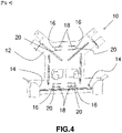
- the figure 4 and 5 illustrate other examples of fixing parts 10, the shape of which has adaptations which are particularly well suited to certain types of telecommunications equipment.
- the figure 4 illustrates a fixing piece 10 adapted to be integrated on a coiling cross
- the figure 5 illustrates a fixing piece 10 adapted to be integrated into an outdoor patch panel.
- the attachment part 10 can be any other accessory.
- the fixing piece 10 and the fixing method in accordance with the present invention can be applied to underground or overhead equipment and to a wide variety of telecommunications equipment ranging from the telephone exchange to residential buildings. It is even possible to envisage other fields of application, including those unrelated to telecommunications.
Landscapes
- Engineering & Computer Science (AREA)
- Microelectronics & Electronic Packaging (AREA)
- Installation Of Indoor Wiring (AREA)
- Clamps And Clips (AREA)
- Supports For Pipes And Cables (AREA)
- Connection Of Plates (AREA)
Abstract
Cette pièce (10) de fixation comporte une surface (12) de fixation réalisée dans une matière déformable et qui présente au moins un trou (14) de fixation et au moins une paire de découpes (16) alignées dégageant chacune une languette (18) de fixation ayant une partie libre (20), les parties libres (20) des languettes (18) de fixation de l'au moins une paire de découpes (16) étant situées à des extrémités opposées des languettes (18).This fixing part (10) comprises a fixing surface (12) made of a deformable material and which has at least one fixing hole (14) and at least one pair of aligned cutouts (16) each releasing a tongue (18) having a free part (20), the free parts (20) of the tabs (18) for fixing the at least one pair of cutouts (16) being located at opposite ends of the tabs (18).
Description
La présente invention se rapporte à une pièce de fixation universelle et à un procédé de fixation associé.The present invention relates to a universal fastener and an associated fastening method.
L'invention appartient au domaine des équipements de télécommunications.The invention belongs to the field of telecommunications equipment.
Les boîtiers de raccordement aériens et souterrains, ainsi que leurs accessoires de gestion de câbles, tels que des croix de lovage ou des panneaux de brassage extérieurs, sont des équipements généralement installés sur des supports de formes très variées. Ces supports peuvent être des parois en fosse ou des façades, présentant donc des surfaces planes, ou des poteaux, à section cylindrique ou polygonale.Aerial and underground junction boxes, as well as their cable management accessories, such as coiling crosses or outdoor patch panels, are equipment generally installed on supports of very varied shapes. These supports can be pit walls or facades, therefore having flat surfaces, or posts, with a cylindrical or polygonal section.
Cela oblige actuellement à créer des pièces spécifiquement adaptées pour servir d'interface entre les boîtiers ou accessoires et leurs supports, afin de permettre une installation facile et efficace des boîtiers et accessoires.This currently requires the creation of parts specifically adapted to act as an interface between the boxes or accessories and their supports, in order to allow easy and efficient installation of the boxes and accessories.
En outre, contrairement aux surfaces planes, les poteaux nécessitent de prévoir un appui en forme de V pour interdire la rotation de l'ensemble accroché et permettre un alignement propre avec l'axe longitudinal du poteau.In addition, unlike flat surfaces, posts need to provide a V-shaped support to prevent rotation of the attached assembly and allow proper alignment with the longitudinal axis of the post.
L'accrochage et le guidage sur les formes de section cylindrique ou polygonale oblige à prévoir une pièce d'accrochage intermédiaire supplémentaire avec une forme en V en relief ou à créer cette forme en V directement sur la pièce d'interface entre l'équipement à fixer et le support.Hooking and guiding on shapes with a cylindrical or polygonal section makes it necessary to provide an additional intermediate hooking part with a V-shape in relief or to create this V-shape directly on the interface part between the equipment to fix and support.
L'ajout de cette pièce de guidage en V ou de cette forme en relief éloigne l'équipement de son support. Cela est préjudiciable au regard des contraintes dues au poids propre de l'équipement installé, qui peut provoquer un effet d'affaissement dans le temps et également au regard des contraintes climatiques, comme le vent continu ou en bourrasques, qui induisent des faiblesses de fatigue.Adding this V-shaped guide piece or raised shape pulls the equipment away from its support. This is detrimental with regard to the stresses due to the own weight of the installed equipment, which can cause a subsidence effect over time and also with regard to climatic stresses, such as continuous or gusty winds, which induce fatigue weaknesses. .
La présente invention a pour but de remédier aux inconvénients précités de l'art antérieur.The object of the present invention is to remedy the aforementioned drawbacks of the prior art.
Dans ce but, la présente invention propose une pièce de fixation comportant une surface de fixation, remarquable en ce que la surface de fixation est réalisée dans une matière déformable et présente au moins un trou de fixation et au moins une paire de découpes alignées dégageant chacune une languette de fixation ayant une partie libre, les parties libres des languettes de fixation de l'au moins une paire de découpes étant situées à des extrémités opposées des languettes.For this purpose, the present invention proposes a fixing part comprising a fixing surface, remarkable in that the fixing surface is made of a deformable material and has at least one fixing hole and at least one pair of aligned cutouts each releasing a securing tab having a free portion, the free portions of the securing tabs of the at least one pair of cutouts being located at opposite ends of the tabs.
Ainsi, l'équipement à installer est au plus près de son support, ce qui évite l'affaissement au fil du temps et le développement de fragilités dues aux contraintes mécaniques.Thus, the equipment to be installed is as close as possible to its support, which avoids subsidence over time and the development of weaknesses due to mechanical stress.
La pièce de fixation conforme à l'invention constitue donc un système de centrage non déporté qui peut être directement intégré à l'équipement à accrocher et qui peut être utilisé quelle que soit la géométrie de la surface du support, notamment que celle-ci soit plane ou que le support ait une section rectangulaire, polygonale ou cylindrique.The fixing part according to the invention therefore constitutes a non-offset centering system which can be directly integrated into the equipment to be hooked and which can be used whatever the geometry of the surface of the support, in particular whether it is plane or that the support has a rectangular, polygonal or cylindrical section.
C'est donc une solution de fixation universelle, convenant à toute forme de support.It is therefore a universal fixing solution, suitable for any form of support.
En outre, le montage d'un équipement sur un support grâce à cette pièce de fixation est simplifié du fait de l'assemblage direct sur le support.In addition, the assembly of equipment on a support thanks to this fixing part is simplified due to the direct assembly on the support.
Par ailleurs, la suppression de toute pièce de guidage intermédiaire réduit le coût de la fixation.Furthermore, the elimination of any intermediate guide piece reduces the cost of the attachment.
Dans un mode particulier de réalisation, la pièce de fixation présente deux trous de fixation.In a particular embodiment, the fixing part has two fixing holes.
Au cas où la surface du support est plane, cela permet de fixer la pièce très simplement par vissage au travers des trous de fixation.If the surface of the support is flat, this makes it possible to fix the part very simply by screwing through the fixing holes.
Dans un mode particulier de réalisation, la pièce de fixation présente deux paires de découpes parallèles.In a particular embodiment, the fastener has two pairs of parallel cutouts.
Cela augmente la sécurité de la fixation au support, car chaque paire de découpes peut recevoir un élément de bridage à fixer au support, ce qui offre donc deux hauteurs différentes de fixation.This increases the security of the fixing to the support, because each pair of cutouts can receive a clamping element to be fixed to the support, which therefore offers two different fixing heights.
Dans le même but que celui indiqué plus haut, la présente invention propose également un procédé de fixation d'un équipement de télécommunications sur un support présentant une géométrie prédéterminée, remarquable en ce qu'il comporte des étapes consistant à :
- intégrer sur l'équipement de télécommunications une pièce de fixation telle que décrite succinctement ci-dessus;
- fixer l'ensemble formé par l'équipement de télécommunications et la pièce de fixation sur le support, les languettes de fixation venant épouser la forme du support.
- integrating on the telecommunications equipment a fixing part as briefly described above;
- fixing the assembly formed by the telecommunications equipment and the fixing part on the support, the fixing tabs matching the shape of the support.
Dans un mode particulier de réalisation du procédé où la géométrie du support est à section rectangulaire, polygonale ou cylindrique, l'étape de fixation comporte une étape consistant à brider la pièce de fixation sur le support en insérant au moins un élément de bridage dans l'au moins une paire de découpes et en fixant l'au moins un élément de bridage sur le support.In a particular embodiment of the method where the geometry of the support has a rectangular, polygonal or cylindrical section, the fixing step comprises a step consisting in clamping the fixing part on the support by inserting at least one clamping element into the at least one pair of cutouts and fixing the at least one clamping element to the support.
Selon une première variante de réalisation, l'au moins un élément de bridage peut être un feuillard métallique.According to a first variant embodiment, the at least one clamping element can be a metal strip.
Selon une seconde variante de réalisation, l'au moins un élément de bridage peut être un collier de serrage.According to a second variant embodiment, the at least one clamping element can be a clamping collar.
Dans un mode particulier de réalisation du procédé où la géométrie du support est plane, l'étape de fixation comporte une étape consistant à insérer au moins un élément de fixation dans l'au moins un trou de fixation et dans le support.In a particular embodiment of the method where the geometry of the support is planar, the fixing step comprises a step consisting in inserting at least one fixing element into the at least one fixing hole and into the support.
Selon une caractéristique particulière possible, l'au moins un élément de fixation peut être une vis.According to one possible particular characteristic, the at least one fastening element can be a screw.
Dans des modes particuliers de réalisation du procédé, l'équipement de télécommunications peut être un boîtier de raccordement de câbles de télécommunications ou une croix de lovage ou un panneau de brassage extérieur.In particular embodiments of the method, the telecommunications equipment can be a telecommunications cable connection box or a coiling cross or an outdoor patch panel.
Le procédé offrant les mêmes avantages que la pièce de fixation, ceux-ci ne sont pas rappelés ici.The process offering the same advantages as the fixing piece, these are not repeated here.
D'autres aspects et avantages de l'invention apparaîtront à la lecture de la description détaillée ci-après de modes particuliers de réalisation, donnés à titre d'exemples nullement limitatifs, en référence aux dessins annexés, dans lesquels :
- [
Fig. 1 ] est une représentation schématique d'une pièce de fixation conforme à la présente invention, dans un mode particulier de réalisation, dans un cas de fixation sur un support plan ; - [
Fig. 2 ] est une représentation schématique d'une pièce de fixation conforme à la présente invention, dans un mode particulier de réalisation, dans un cas de fixation sur un support à section rectangulaire ; - [
Fig. 3 ] est une représentation schématique d'une pièce de fixation conforme à la présente invention, dans un mode particulier de réalisation, dans un cas de fixation sur un support à section cylindrique ; - [
Fig. 4 ] est une représentation schématique d'une pièce de fixation conforme à la présente invention, dans un mode particulier de réalisation adapté à la fixation d'une croix de lovage ; - [
Fig. 5 ] est une représentation schématique d'une pièce de fixation conforme à la présente invention, dans un mode particulier de réalisation adapté à la fixation d'un panneau de brassage extérieur ; - [
Fig. 6 ] est un organigramme illustrant des étapes d'un procédé de fixation conforme à la présente invention, dans un mode particulier de réalisation.
- [
Fig. 1 ] is a schematic representation of a fastener according to the present invention, in a particular embodiment, in the case of fastening on a flat support; - [
Fig. 2 ] is a schematic representation of a fastener according to the present invention, in a particular embodiment, in the case of fastening on a support with a rectangular section; - [
Fig. 3 ] is a schematic representation of a fastener according to the present invention, in a particular embodiment, in the case of fastening on a support with a cylindrical section; - [
Fig. 4 ] is a schematic representation of a fastener according to the present invention, in a particular embodiment suitable for fixing a coiling cross; - [
Fig. 5 ] is a schematic representation of a fixing piece according to the present invention, in a particular embodiment suitable for fixing an outdoor patch panel; - [
Fig. 6 ] is a flowchart illustrating the steps of a fixing method according to the present invention, in a particular embodiment.
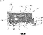
Comme le montre la
Conformément à la présente invention, la surface 12 de fixation est réalisée dans une matière déformable. Cette matière peut être métallique ou plastique, ces exemples n'étant cependant pas limitatifs. En outre, la surface 12 de fixation présente un ou plusieurs trous 14 de fixation et une ou plusieurs paires de découpes 16.In accordance with the present invention, the
La surface 12 de fixation peut par exemple comporter deux trous 14 de fixation, comme dans le mode de réalisation de la
Les découpes 16 de chaque paire sont alignées. Chaque découpe 16 dégage une languette 18 de fixation qui a une partie libre 20.The
Pour une paire de découpes 16 donnée, les parties libres 20 des languettes 18 de fixation sont situées à des extrémités opposées des languettes 18.For a given pair of
Dans le mode de réalisation de la
Comme le montre l'organigramme de la
A titre d'exemple nullement limitatif, l'équipement de télécommunications peut être un boîtier de raccordement de câbles de télécommunications, ou une croix de lovage, ou encore un panneau de brassage extérieur.By way of non-limiting example, the telecommunications equipment can be a telecommunications cable connection box, or a coiling cross, or even an outdoor patch panel.
L'étape 60 d'intégration peut être réalisée par tout moyen jugé approprié. Par exemple, des trous additionnels de fixation peuvent être prévus dans la pièce 10 de fixation à cet effet, pour solidariser la pièce 10 de fixation et l'équipement de télécommunications par l'intermédiaire d'éléments de fixation tels que vis, écrous ou boulons venant s'insérer dans ces trous.The
Puis une étape 62 consiste à fixer l'ensemble formé par l'équipement de télécommunications et la pièce 10 de fixation sur le support. Lors de cette étape 62, les languettes 18 de fixation viennent épouser la forme du support.Then a
Ainsi, si la géométrie du support est à section rectangulaire comme sur la
Si la géométrie du support est plane, dans un autre mode particulier de réalisation, comme celui de la
Les
La pièce 10 de fixation et le procédé de fixation conformes à la présente invention peuvent s'appliquer à des équipements souterrains ou aériens et à une grande variété d'équipements de télécommunications allant du central téléphonique jusqu'à des bâtiments d'habitation. On peut même envisager d'autres domaines d'application, y compris sans rapport avec les télécomuunications.The fixing
Claims (10)
Applications Claiming Priority (1)
| Application Number | Priority Date | Filing Date | Title |
|---|---|---|---|
| FR2104646A FR3122533B1 (en) | 2021-05-03 | 2021-05-03 | UNIVERSAL FASTENING PIECE AND ASSOCIATED FIXING METHOD |
Publications (1)
| Publication Number | Publication Date |
|---|---|
| EP4087073A1 true EP4087073A1 (en) | 2022-11-09 |
Family
ID=77021453
Family Applications (1)
| Application Number | Title | Priority Date | Filing Date |
|---|---|---|---|
| EP22169760.0A Withdrawn EP4087073A1 (en) | 2021-05-03 | 2022-04-25 | Universal attachment part and associated attachment method |
Country Status (2)
| Country | Link |
|---|---|
| EP (1) | EP4087073A1 (en) |
| FR (1) | FR3122533B1 (en) |
Citations (3)
| Publication number | Priority date | Publication date | Assignee | Title |
|---|---|---|---|---|
| US5193774A (en) * | 1992-05-26 | 1993-03-16 | Rogers J W | Mounting bracket apparatus |
| US20100314514A1 (en) * | 2009-06-16 | 2010-12-16 | Bogen Communications Inc. | Mounting bracket |
| KR20160071728A (en) * | 2014-12-12 | 2016-06-22 | 삼성전자주식회사 | Mounting bracket set for rru |
-
2021
- 2021-05-03 FR FR2104646A patent/FR3122533B1/en active Active
-
2022
- 2022-04-25 EP EP22169760.0A patent/EP4087073A1/en not_active Withdrawn
Patent Citations (3)
| Publication number | Priority date | Publication date | Assignee | Title |
|---|---|---|---|---|
| US5193774A (en) * | 1992-05-26 | 1993-03-16 | Rogers J W | Mounting bracket apparatus |
| US20100314514A1 (en) * | 2009-06-16 | 2010-12-16 | Bogen Communications Inc. | Mounting bracket |
| KR20160071728A (en) * | 2014-12-12 | 2016-06-22 | 삼성전자주식회사 | Mounting bracket set for rru |
Also Published As
| Publication number | Publication date |
|---|---|
| FR3122533A1 (en) | 2022-11-04 |
| FR3122533B1 (en) | 2023-04-07 |
Similar Documents
| Publication | Publication Date | Title |
|---|---|---|
| FR3067738A1 (en) | CLIP FOR ASSEMBLING A CARPENTRY IN AN OPENING | |
| EP4087073A1 (en) | Universal attachment part and associated attachment method | |
| EP1606868A2 (en) | System for electrically connecting and fixing at least one conductor to a support piece | |
| EP0974706B1 (en) | Movable partition wall | |
| BE1004732A6 (en) | Brackets cables and other similar body extensions. | |
| FR2711753A1 (en) | Composite brake disc ventilated from the inside. | |
| FR2984025A1 (en) | EQUIPOTENTIAL CONNECTION SYSTEM FOR PANEL | |
| EP3997759B1 (en) | Connection device for grounding an electrical apparatus and/or creating an equipotential link between conductive elements | |
| EP0444979A1 (en) | Caged nut | |
| FR2730354A1 (en) | Electrical equipment mounting box fixing system | |
| FR2721087A1 (en) | Support device for chute. | |
| FR2948955A1 (en) | Photovoltaic modules assembling system for dwelling, has support including fixation opening for mounting photovoltaic module and another fixation opening provided on roofing framework along axis of upper part of profile | |
| EP2076645B1 (en) | Belt for electromagnetic sucker | |
| EP2694826A1 (en) | Device for securing an assembly screw to an element before being fixed to another element | |
| FR2815184A1 (en) | SNAP-IN PLATES FOR WIRE MESH CABLE TRAYS, MOUNTING OF SUCH PLATES ON CABLE TRAYS | |
| FR2727577A1 (en) | Four face electrical supply, control and distribution for housing cables for supply or lighting | |
| JP3218691U (en) | Photovoltaic generator support stand connection kit | |
| WO2004036685A1 (en) | Device and method for fixing an antenna on a mast | |
| EP3916168B1 (en) | Bracing device for cladding elements | |
| FR2528484A1 (en) | Fixing for juxtaposed panel dressing to wall - has profiles on wall and retaining clips anchoring panel edges | |
| FR2741136A1 (en) | BYPASS SUPPORT, IN PARTICULAR FOR WIRE ROPE PATH | |
| FR3065426A1 (en) | DEVICE FOR FASTENING A ROOF OR SUB-CHASSIS ELEMENT OF A RAILWAY VEHICLE | |
| EP1193820B1 (en) | Accessories holder for cable trays and cable trays incorporating the same | |
| FR3122541A1 (en) | Structure for receiving photovoltaic panels | |
| FR2779759A1 (en) | TENT EYELET |
Legal Events
| Date | Code | Title | Description |
|---|---|---|---|
| PUAI | Public reference made under article 153(3) epc to a published international application that has entered the european phase |
Free format text: ORIGINAL CODE: 0009012 |
|
| STAA | Information on the status of an ep patent application or granted ep patent |
Free format text: STATUS: THE APPLICATION HAS BEEN PUBLISHED |
|
| AK | Designated contracting states |
Kind code of ref document: A1 Designated state(s): AL AT BE BG CH CY CZ DE DK EE ES FI FR GB GR HR HU IE IS IT LI LT LU LV MC MK MT NL NO PL PT RO RS SE SI SK SM TR |
|
| STAA | Information on the status of an ep patent application or granted ep patent |
Free format text: STATUS: REQUEST FOR EXAMINATION WAS MADE |
|
| 17P | Request for examination filed |
Effective date: 20230509 |
|
| RBV | Designated contracting states (corrected) |
Designated state(s): AL AT BE BG CH CY CZ DE DK EE ES FI FR GB GR HR HU IE IS IT LI LT LU LV MC MK MT NL NO PL PT RO RS SE SI SK SM TR |
|
| GRAP | Despatch of communication of intention to grant a patent |
Free format text: ORIGINAL CODE: EPIDOSNIGR1 |
|
| STAA | Information on the status of an ep patent application or granted ep patent |
Free format text: STATUS: GRANT OF PATENT IS INTENDED |
|
| INTG | Intention to grant announced |
Effective date: 20230704 |
|
| STAA | Information on the status of an ep patent application or granted ep patent |
Free format text: STATUS: THE APPLICATION IS DEEMED TO BE WITHDRAWN |
|
| 18D | Application deemed to be withdrawn |
Effective date: 20231115 |