EP4087069A2 - Metal single-piece blank for assembly by crimping of a connector to an insulated cable, preassembled connector subassembly including the blank or comprising a central contact and two parts for crimping of different material and/or thickness, associated methods for assembling a connector to a cable. - Google Patents
Metal single-piece blank for assembly by crimping of a connector to an insulated cable, preassembled connector subassembly including the blank or comprising a central contact and two parts for crimping of different material and/or thickness, associated methods for assembling a connector to a cable. Download PDFInfo
- Publication number
- EP4087069A2 EP4087069A2 EP22156115.2A EP22156115A EP4087069A2 EP 4087069 A2 EP4087069 A2 EP 4087069A2 EP 22156115 A EP22156115 A EP 22156115A EP 4087069 A2 EP4087069 A2 EP 4087069A2
- Authority
- EP
- European Patent Office
- Prior art keywords
- crimping
- cable
- connector
- assembly
- around
- Prior art date
- Legal status (The legal status is an assumption and is not a legal conclusion. Google has not performed a legal analysis and makes no representation as to the accuracy of the status listed.)
- Pending
Links
Images


Classifications
-
- H—ELECTRICITY
- H01—ELECTRIC ELEMENTS
- H01R—ELECTRICALLY-CONDUCTIVE CONNECTIONS; STRUCTURAL ASSOCIATIONS OF A PLURALITY OF MUTUALLY-INSULATED ELECTRICAL CONNECTING ELEMENTS; COUPLING DEVICES; CURRENT COLLECTORS
- H01R4/00—Electrically-conductive connections between two or more conductive members in direct contact, i.e. touching one another; Means for effecting or maintaining such contact; Electrically-conductive connections having two or more spaced connecting locations for conductors and using contact members penetrating insulation
- H01R4/10—Electrically-conductive connections between two or more conductive members in direct contact, i.e. touching one another; Means for effecting or maintaining such contact; Electrically-conductive connections having two or more spaced connecting locations for conductors and using contact members penetrating insulation effected solely by twisting, wrapping, bending, crimping, or other permanent deformation
- H01R4/18—Electrically-conductive connections between two or more conductive members in direct contact, i.e. touching one another; Means for effecting or maintaining such contact; Electrically-conductive connections having two or more spaced connecting locations for conductors and using contact members penetrating insulation effected solely by twisting, wrapping, bending, crimping, or other permanent deformation by crimping
- H01R4/183—Electrically-conductive connections between two or more conductive members in direct contact, i.e. touching one another; Means for effecting or maintaining such contact; Electrically-conductive connections having two or more spaced connecting locations for conductors and using contact members penetrating insulation effected solely by twisting, wrapping, bending, crimping, or other permanent deformation by crimping for cylindrical elongated bodies, e.g. cables having circular cross-section
-
- H—ELECTRICITY
- H01—ELECTRIC ELEMENTS
- H01R—ELECTRICALLY-CONDUCTIVE CONNECTIONS; STRUCTURAL ASSOCIATIONS OF A PLURALITY OF MUTUALLY-INSULATED ELECTRICAL CONNECTING ELEMENTS; COUPLING DEVICES; CURRENT COLLECTORS
- H01R43/00—Apparatus or processes specially adapted for manufacturing, assembling, maintaining, or repairing of line connectors or current collectors or for joining electric conductors
- H01R43/04—Apparatus or processes specially adapted for manufacturing, assembling, maintaining, or repairing of line connectors or current collectors or for joining electric conductors for forming connections by deformation, e.g. crimping tool
- H01R43/048—Crimping apparatus or processes
- H01R43/0482—Crimping apparatus or processes combined with contact member manufacturing mechanism
-
- H—ELECTRICITY
- H01—ELECTRIC ELEMENTS
- H01R—ELECTRICALLY-CONDUCTIVE CONNECTIONS; STRUCTURAL ASSOCIATIONS OF A PLURALITY OF MUTUALLY-INSULATED ELECTRICAL CONNECTING ELEMENTS; COUPLING DEVICES; CURRENT COLLECTORS
- H01R13/00—Details of coupling devices of the kinds covered by groups H01R12/70 or H01R24/00 - H01R33/00
- H01R13/02—Contact members
- H01R13/22—Contacts for co-operating by abutting
-
- H—ELECTRICITY
- H01—ELECTRIC ELEMENTS
- H01R—ELECTRICALLY-CONDUCTIVE CONNECTIONS; STRUCTURAL ASSOCIATIONS OF A PLURALITY OF MUTUALLY-INSULATED ELECTRICAL CONNECTING ELEMENTS; COUPLING DEVICES; CURRENT COLLECTORS
- H01R13/00—Details of coupling devices of the kinds covered by groups H01R12/70 or H01R24/00 - H01R33/00
- H01R13/40—Securing contact members in or to a base or case; Insulating of contact members
-
- H—ELECTRICITY
- H01—ELECTRIC ELEMENTS
- H01R—ELECTRICALLY-CONDUCTIVE CONNECTIONS; STRUCTURAL ASSOCIATIONS OF A PLURALITY OF MUTUALLY-INSULATED ELECTRICAL CONNECTING ELEMENTS; COUPLING DEVICES; CURRENT COLLECTORS
- H01R13/00—Details of coupling devices of the kinds covered by groups H01R12/70 or H01R24/00 - H01R33/00
- H01R13/62—Means for facilitating engagement or disengagement of coupling parts or for holding them in engagement
-
- H—ELECTRICITY
- H01—ELECTRIC ELEMENTS
- H01R—ELECTRICALLY-CONDUCTIVE CONNECTIONS; STRUCTURAL ASSOCIATIONS OF A PLURALITY OF MUTUALLY-INSULATED ELECTRICAL CONNECTING ELEMENTS; COUPLING DEVICES; CURRENT COLLECTORS
- H01R4/00—Electrically-conductive connections between two or more conductive members in direct contact, i.e. touching one another; Means for effecting or maintaining such contact; Electrically-conductive connections having two or more spaced connecting locations for conductors and using contact members penetrating insulation
- H01R4/10—Electrically-conductive connections between two or more conductive members in direct contact, i.e. touching one another; Means for effecting or maintaining such contact; Electrically-conductive connections having two or more spaced connecting locations for conductors and using contact members penetrating insulation effected solely by twisting, wrapping, bending, crimping, or other permanent deformation
- H01R4/18—Electrically-conductive connections between two or more conductive members in direct contact, i.e. touching one another; Means for effecting or maintaining such contact; Electrically-conductive connections having two or more spaced connecting locations for conductors and using contact members penetrating insulation effected solely by twisting, wrapping, bending, crimping, or other permanent deformation by crimping
- H01R4/183—Electrically-conductive connections between two or more conductive members in direct contact, i.e. touching one another; Means for effecting or maintaining such contact; Electrically-conductive connections having two or more spaced connecting locations for conductors and using contact members penetrating insulation effected solely by twisting, wrapping, bending, crimping, or other permanent deformation by crimping for cylindrical elongated bodies, e.g. cables having circular cross-section
- H01R4/184—Electrically-conductive connections between two or more conductive members in direct contact, i.e. touching one another; Means for effecting or maintaining such contact; Electrically-conductive connections having two or more spaced connecting locations for conductors and using contact members penetrating insulation effected solely by twisting, wrapping, bending, crimping, or other permanent deformation by crimping for cylindrical elongated bodies, e.g. cables having circular cross-section comprising a U-shaped wire-receiving portion
- H01R4/185—Electrically-conductive connections between two or more conductive members in direct contact, i.e. touching one another; Means for effecting or maintaining such contact; Electrically-conductive connections having two or more spaced connecting locations for conductors and using contact members penetrating insulation effected solely by twisting, wrapping, bending, crimping, or other permanent deformation by crimping for cylindrical elongated bodies, e.g. cables having circular cross-section comprising a U-shaped wire-receiving portion combined with a U-shaped insulation-receiving portion
-
- H—ELECTRICITY
- H01—ELECTRIC ELEMENTS
- H01R—ELECTRICALLY-CONDUCTIVE CONNECTIONS; STRUCTURAL ASSOCIATIONS OF A PLURALITY OF MUTUALLY-INSULATED ELECTRICAL CONNECTING ELEMENTS; COUPLING DEVICES; CURRENT COLLECTORS
- H01R43/00—Apparatus or processes specially adapted for manufacturing, assembling, maintaining, or repairing of line connectors or current collectors or for joining electric conductors
- H01R43/04—Apparatus or processes specially adapted for manufacturing, assembling, maintaining, or repairing of line connectors or current collectors or for joining electric conductors for forming connections by deformation, e.g. crimping tool
- H01R43/048—Crimping apparatus or processes
- H01R43/055—Crimping apparatus or processes with contact member feeding mechanism
-
- H—ELECTRICITY
- H01—ELECTRIC ELEMENTS
- H01R—ELECTRICALLY-CONDUCTIVE CONNECTIONS; STRUCTURAL ASSOCIATIONS OF A PLURALITY OF MUTUALLY-INSULATED ELECTRICAL CONNECTING ELEMENTS; COUPLING DEVICES; CURRENT COLLECTORS
- H01R43/00—Apparatus or processes specially adapted for manufacturing, assembling, maintaining, or repairing of line connectors or current collectors or for joining electric conductors
- H01R43/04—Apparatus or processes specially adapted for manufacturing, assembling, maintaining, or repairing of line connectors or current collectors or for joining electric conductors for forming connections by deformation, e.g. crimping tool
- H01R43/058—Crimping mandrels
- H01R43/0585—Crimping mandrels for crimping apparatus with more than two radially actuated mandrels
-
- H—ELECTRICITY
- H01—ELECTRIC ELEMENTS
- H01R—ELECTRICALLY-CONDUCTIVE CONNECTIONS; STRUCTURAL ASSOCIATIONS OF A PLURALITY OF MUTUALLY-INSULATED ELECTRICAL CONNECTING ELEMENTS; COUPLING DEVICES; CURRENT COLLECTORS
- H01R43/00—Apparatus or processes specially adapted for manufacturing, assembling, maintaining, or repairing of line connectors or current collectors or for joining electric conductors
- H01R43/16—Apparatus or processes specially adapted for manufacturing, assembling, maintaining, or repairing of line connectors or current collectors or for joining electric conductors for manufacturing contact members, e.g. by punching and by bending
-
- H—ELECTRICITY
- H01—ELECTRIC ELEMENTS
- H01R—ELECTRICALLY-CONDUCTIVE CONNECTIONS; STRUCTURAL ASSOCIATIONS OF A PLURALITY OF MUTUALLY-INSULATED ELECTRICAL CONNECTING ELEMENTS; COUPLING DEVICES; CURRENT COLLECTORS
- H01R43/00—Apparatus or processes specially adapted for manufacturing, assembling, maintaining, or repairing of line connectors or current collectors or for joining electric conductors
- H01R43/20—Apparatus or processes specially adapted for manufacturing, assembling, maintaining, or repairing of line connectors or current collectors or for joining electric conductors for assembling or disassembling contact members with insulating base, case or sleeve
-
- H—ELECTRICITY
- H01—ELECTRIC ELEMENTS
- H01R—ELECTRICALLY-CONDUCTIVE CONNECTIONS; STRUCTURAL ASSOCIATIONS OF A PLURALITY OF MUTUALLY-INSULATED ELECTRICAL CONNECTING ELEMENTS; COUPLING DEVICES; CURRENT COLLECTORS
- H01R9/00—Structural associations of a plurality of mutually-insulated electrical connecting elements, e.g. terminal strips or terminal blocks; Terminals or binding posts mounted upon a base or in a case; Bases therefor
- H01R9/03—Connectors arranged to contact a plurality of the conductors of a multiconductor cable, e.g. tapping connections
- H01R9/05—Connectors arranged to contact a plurality of the conductors of a multiconductor cable, e.g. tapping connections for coaxial cables
- H01R9/0518—Connection to outer conductor by crimping or by crimping ferrule
-
- H—ELECTRICITY
- H01—ELECTRIC ELEMENTS
- H01R—ELECTRICALLY-CONDUCTIVE CONNECTIONS; STRUCTURAL ASSOCIATIONS OF A PLURALITY OF MUTUALLY-INSULATED ELECTRICAL CONNECTING ELEMENTS; COUPLING DEVICES; CURRENT COLLECTORS
- H01R13/00—Details of coupling devices of the kinds covered by groups H01R12/70 or H01R24/00 - H01R33/00
- H01R13/46—Bases; Cases
- H01R13/52—Dustproof, splashproof, drip-proof, waterproof, or flameproof cases
- H01R13/5205—Sealing means between cable and housing, e.g. grommet
-
- H—ELECTRICITY
- H01—ELECTRIC ELEMENTS
- H01R—ELECTRICALLY-CONDUCTIVE CONNECTIONS; STRUCTURAL ASSOCIATIONS OF A PLURALITY OF MUTUALLY-INSULATED ELECTRICAL CONNECTING ELEMENTS; COUPLING DEVICES; CURRENT COLLECTORS
- H01R13/00—Details of coupling devices of the kinds covered by groups H01R12/70 or H01R24/00 - H01R33/00
- H01R13/648—Protective earth or shield arrangements on coupling devices, e.g. anti-static shielding
- H01R13/658—High frequency shielding arrangements, e.g. against EMI [Electro-Magnetic Interference] or EMP [Electro-Magnetic Pulse]
- H01R13/6581—Shield structure
-
- H—ELECTRICITY
- H01—ELECTRIC ELEMENTS
- H01R—ELECTRICALLY-CONDUCTIVE CONNECTIONS; STRUCTURAL ASSOCIATIONS OF A PLURALITY OF MUTUALLY-INSULATED ELECTRICAL CONNECTING ELEMENTS; COUPLING DEVICES; CURRENT COLLECTORS
- H01R2201/00—Connectors or connections adapted for particular applications
- H01R2201/26—Connectors or connections adapted for particular applications for vehicles
-
- H—ELECTRICITY
- H01—ELECTRIC ELEMENTS
- H01R—ELECTRICALLY-CONDUCTIVE CONNECTIONS; STRUCTURAL ASSOCIATIONS OF A PLURALITY OF MUTUALLY-INSULATED ELECTRICAL CONNECTING ELEMENTS; COUPLING DEVICES; CURRENT COLLECTORS
- H01R24/00—Two-part coupling devices, or either of their cooperating parts, characterised by their overall structure
- H01R24/38—Two-part coupling devices, or either of their cooperating parts, characterised by their overall structure having concentrically or coaxially arranged contacts
- H01R24/40—Two-part coupling devices, or either of their cooperating parts, characterised by their overall structure having concentrically or coaxially arranged contacts specially adapted for high frequency
Definitions
- the present invention relates to the field of electrical connectors.
- the invention aims in particular to improve the assembly of a connector to an insulated cable, in particular of a power connector to a cable with a large section for the passage of high currents.
- They may be power connectors connecting, for example, the battery of a vehicle to the electric motor or to the power electronics.
- These may be connectors conveying other types of signals, such as RF signals, or data.
- connectors for motor vehicles and more particularly, for hybrid and electric vehicles, the invention can be implemented in any other application.
- HVP-800 range a two-way connector marketed by the companies Tyco Electronics Connectivity under the trade name “HVP-800 range”, Aptiv under the name “RCS800 range” or even Rosenberger under the name “HVR200 range”.
- the risk of forgetting a part and/or making an error in the direction or assembly order is high and generates scrapping of poorly assembled connectors with a cable.
- the assembly must be carried out by successively threading the various components (retaining part, gasket, internal and external ferrules, electrical insulator, protection of the central contact, electromagnetic shielding ring) of the connector on a cable, with crimping at each assembly stage of an electrically conductive component (contact).
- the invention aims to meet all or part of this need.
- the front part is a crimping part.
- each of the two crimping parts advantageously comprises a receiving barrel and at least one crimping fin connected to the barrel, one of the barrels being intended to receive the electrical component of the connector.
- the one-piece blank comprises at least one support blade, connected to the support and which extends inside the latter between the two crimping parts so as to form a support zone of an electrical component of the connector received in one of the two crimping parts.
- the front crimping part comprises at least one crimping fin adapted to be crimped around the electrical component, preferably around an electrical insulating part housing a preassembled central contact.
- the rear crimping part preferably comprises at least one crimping fin adapted to be crimped around the shield braid of the insulated cable.
- the rear crimping part may comprise at least one crimping fin adapted to be crimped around the outer and/or inner insulation sheath of the insulated cable or around a seal fitted around the outer sheath of the insulated cable .
- the rear crimping part is continuous.
- Each of the two parts is preferably held to the support by at least one fastener which extends along the longitudinal axis (X) and/or laterally thereto.
- the electrical component is crimped onto the one-piece blank via the front part.
- the invention also relates to a reel for the automatic or semi-automatic assembly by crimping of a connector to a cable, comprising a plurality of sub-assemblies as above, joined by one edge of the supports of the blanks and wound around a mandrel.
- step i1/ further comprises supplying a seal fitted around the outer or inner sheath of the cable, step iv/ further comprising crimping the rear part of the sub- together, preferably simultaneously with its crimping on the shielding braid, on the seal.
- step v1/ is a mechanical cut using a blade or a mechanical shear cut or a laser cut.
- the method comprises after step v/ cutting, the following step: vi1/fitting of the central contact crimped around the conductive wire(s) in the electrical insulating part (3) to obtain their final assembly.
- Another subject of the invention is a wired unitary contact, if necessary shielded, obtained by the process described above.
- the subject of the invention is a connector, in particular a multiway connector, obtained by the process described above.
- the invention according to this first alternative consists in the first place in defining a one-piece metal blank which will make it possible to produce a connector subassembly ready to be directly crimped to a shielded and insulated cable, prepared beforehand, which makes it possible to minimize the assembly steps and the associated risks such as those linked to the process of threading multitudes of components according to the state of the art.
- the invention also relates, according to a second alternative of the invention, to a preassembled electrically conductive subassembly which extends along a longitudinal axis (X), to be assembled by crimping on a cable comprising an electrically conductive core and at the at least one electrically insulating sheath and, where applicable, a shielding braid around the core, the subassembly comprising a central contact and comprising at least two crimping parts, electrically conductive, in the axial extension of the cylindrical body, the part of which the part closest to the body, called the front part, is adapted to be crimped around the core of the cable, while the part farthest from the body, called the rear part, is adapted to be crimped around the insulating sheath and/or the where appropriate around the shielding braid, the front and rear crimping parts being of different constituent material and/or thickness.
- X longitudinal axis
- the front and rear crimping parts being of different constituent material and joined by an electrically conductive or insulating junction. It is thus possible to differentiate the nature of the materials according to the part of a cable to be crimped: the core being directly subjected to the passage of current, in particular of power, the front part of crimping can be in a material of high conductivity, while that the metal braid only serving as electromagnetic shielding, the rear crimping part can be made of a material of lower conductivity. It is also possible to provide an electrically insulating rear part.
- the junction is formed by riveting, clinching, brazing or welding or gluing.
- the rear crimping part is continuous.
- each of the two crimping parts comprises at least one receiving barrel and at least one crimping fin connected to the barrel, the barrel of the front crimping part being intended to receive the core of the cable while the barrel of the rear crimping part is intended to receive the insulating sheath and/or the braid of the cable.
- the rear crimping part comprises at least one crimping fin adapted to be crimped around the outer and/or inner insulation sheath of the insulated cable or around a seal fitted around the outer sheath of the insulated cable.
- the rear crimping part advantageously comprises at least one crimping fin adapted to be crimped around the shielding braid of the cable.
- the preassembled central contact comprises an electrically insulating part in which the electrically conductive body is housed.
- the invention also relates to a coil for the automatic or semi-automatic assembly by crimping of a connector to a cable, comprising a plurality of sub-assemblies according to the second alternative of the invention as above, mechanically connected together by at least one carrying strip and wound around a mandrel.
- the carrier strip is mechanically connected or integrated into the front or rear crimping part or, where appropriate, connected to the junction between the front and rear parts.
- the carrier strip is pierced with a plurality of guide holes to guide the carrier strip during the scrolling of the reel.
- the method comprises, when step ii2/ is carried out from the reel, a step iii′2/ of cutting out the carrier strip, if necessary simultaneously with step iii2/ of positioning the cable.
- Step iii′2/ is preferably mechanical cutting of the carrier strip by means of a blade or mechanical shear cutting or laser cutting.
- step iv2/ is carried out with at least part of the pre-assembled sub-assembly placed on a crimping support.
- step i2/ further comprises the supply of a seal fitted around the outer or inner sheath of the cable, step iv2/ further comprising the crimping of the rear part of the sub- together, preferably simultaneously with its crimping on the shielding braid, on the seal.
- Another subject of the invention is a wired unitary contact, if necessary shielded, obtained by the process described above.
- the invention according to the second alternative consists in the first place in defining a preassembled connector sub-assembly which integrates front and rear crimping parts with different electrical and/or mechanical characteristics, and which is ready to be crimped directly to a shielded and insulated cable, prepared beforehand, which makes it possible to minimize the assembly stages and the associated risks such as those linked to the process of threading multitudes of components according to the state of the art.
- the advantages of the solution according to the second alternative of the invention are the space saving and the possibility of using less metallic material during continuous assembly, due to the implementation of a simple carrier strip, and due to a pitch between two successive preassembled subassemblies reduced, and therefore a lower cost.
- the invention can be declined for different applications and cable diameters (from 6kW to about 300kW).
- front and rear are to be understood with respect to the connection face of an electrical connector according to the invention.
- the front crimping part of a one-piece blank is the one intended to be crimped to the front of a connector while the rear part is the one intended to be crimped to the rear of the connector by which the shielded cable is positioned.
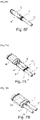
- FIG. 1 We represented on the figure 1 an example of shielded and insulated power cable, generally designated by the reference numeral 1, intended to be assembled with a connector subassembly according to the invention.
- the cable 1 comprises one or more electrical conductors 10, of large section and insulated from the outside by an outer sheath 11 of electrically insulating material.
- the cable 1 also comprises a metal braid 12 for electromagnetic shielding surrounding the conductor(s) 10 and insulated therefrom by an inner sheath 13 of electrically insulating material.
- the cable 1 can comprise a metal tape or a metal/plastic composite material 14 which has the advantage of having excellent electromagnetic coverage, typically of the order of 100%.
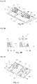
- Step 1/ A central contact 2 is preassembled. To do this, a part forming a socket 21 with petals, made of electrically conductive material, is fitted and crimped in a cylindrical body 20, electrically conductive ( Figures 2A, 2B ). The crimping operation can be replaced by a snapping operation.
- the sleeve 21 is extended at the rear by a generally U-shaped crimping part comprising a receiving barrel 22 and two crimping fins 23 connected to the barrel 22, preferably being symmetrical on either side of the barrel.
- Step 2/ The pre-assembled central contact 2 is then fitted and fixed in an electrical insulating part 3. More precisely, this assembly is made so as to have the cylindrical body 20 completely housed and fixed inside a cylindrical body 30 electrical insulator and the crimping part 22, 23 which protrudes at the rear of the insulating body 30, delimited by a cylindrical support portion 31, as detailed below ( figures 2C, 2D ).
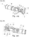
- Step 3/ A one-piece metal blank 5 is provided for assembly by crimping ( figure 2E ).
- the assembly can also be carried out by a force fitting or clipping or overmolding technique, as detailed below.
- This metal blank is produced by a cut-out technique, preferably rolled from a continuous strip.
- This one-piece blank 5 firstly comprises a peripheral strip 50 forming a perforated support which extends along a longitudinal axis X and which has in the example illustrated overall the shape of a rectangular frame.
- Two respectively front and rear crimping parts 51, 52 each extend along the longitudinal axis X while being separated from each other, and are held to the support 50 by at least one blade 53, 54 forming a attached. These fasteners can also be found along the longitudinal axis X.
- two lateral fasteners 53, 54 are provided which extend on either side of each of the crimping parts 51, 52. These side fasteners 53, 54 have the function of holding the crimping parts 51, 52 once the connector sub-assembly has been produced.
- the front crimping part 51 comprising a receiving barrel 56 and at least one crimping fin 57 connected to the barrel 56 and intended to receive and to be crimped around the electrical insulating part 3 housing the preassembled central contact 2.
- the rear crimping part 52 comprising a receiving barrel 58 and at least one crimping fin 59 connected to the barrel 58 adapted to be crimped around the shielding braid 12 of the insulated cable 1.
- the rear crimping part also comprises at least one crimping fin 59.2 adapted to be crimped around a seal 7. In the case where sealing is not required, the seal is not necessary and the crimping fin is directly crimped around the outer sheath of the cable.
- the rear crimping part 52 is continuous to guarantee electrical ground continuity.
- the one-piece blank 5 further comprises a support blade 55, connected to the support 50 and which extends inside the latter between the two crimping parts 51, 52 so as to form a support zone for the electrical insulating part 3.
- the support strip 55 is continuous from one longitudinal edge to the other of the support 50.
- the central portion of the support strip 55 is shaped as a cylinder portion complementary to the support portion 31. It can be in the form of a blade, one end of which is connected to a longitudinal edge of the support 50 and the free end serves as a support for the portion 31 of the electrical insulator 3.
- the arrangement of the front and rear crimping parts 51, 52, of the various fasteners 53, 54 and of the support blade 55 relative to the preferably flat support 50 defines empty spaces (V) or openings between and around the parts of crimping. These empty spaces (V) make it possible to pass crimping jaws dimensioned to be robust, and therefore to crimp cables 1 of large section, in particular power cables.
- Step 4/ Position the electrical insulator 3 in the front crimping part 51 of the blank 5 ( figure 2E ). More precisely, the positioning is carried out so that the body 30 of the insulator 3 comes to marry the crimping barrel 56 and the cylindrical portion 31 comes to bear against the support blade 55.
- the crimping fins 57 are then folded around the cylindrical body 30.
- the electrical insulator 3 is then crimped in the one-piece blank 5, which forms a connector sub-assembly 6 intended for assembly by crimping with a cable 1 ( figure 2F ).
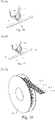
- the continuous strip can take the form of a continuous reel 60 wound around a chuck ( figure 4 ).
- This coil 60 can be made entirely in an assembly unit independent of an assembly unit with a cable 1.
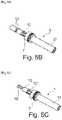
- Step 1/ The outer sheath 11 and the inner sheath 13 are respectively pre-stripped to reveal the conductor(s) 10 and the metal braid 12 over a predetermined length ( figure 5A ).
- Step 2/ A seal 7 is fitted around the outer sheath 11 of the cable 1 ( figure 5B ). According to a variant, this step 2/ can take place before step 1/ to avoid any potential damage to the metal braid.
- Step 3/ Remove the bare part of the inner sheath 13 of the cable 1 ( Fig. 5C ).
- Step 11/ A cable 1 prepared according to the figures 5A to 5C .
- Step ii/ A sub-assembly 6 is supplied from a blank from the reel 60.
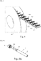
- Step iii1/ The cable 1 is positioned in the sub-assembly 6 so that the stripped part 10 of the conductive wire(s) 1 is housed in the crimping part 22, 23 of the preassembled central contact 2 and that the stripped part of the shielding braid 12 and the seal 7 comes to be housed in the barrel 58 of the rear crimping part 52 of the sub-assembly 6 ( Figure 6A ).
- Step ivl/ The crimping is carried out simultaneously, by means of a tool of the jaw-anvil type (M), inserted into the openings or empty spaces (V) between the support 50 and the fastener(s) 53 , 54 and the support blade(s) 55, on the one hand of the crimping part 22, 23 of the central contact preassembled on the conductive wire(s) 10 and, on the other hand, on the other hand, of the rear crimping part 52 of the sub-assembly on the shielding braid 12 and on the seal 7 ( figure 6B ).
- the robust jaws M simultaneously fold the pair of crimping fins 23 around the conductor(s) 10 and each of the two pairs of crimping fins 59.1 and 59.2 respectively around the metallic shielding braid 12 and gasket seal 7.
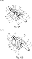
- Step v1/ The cutting is then carried out either mechanically by means of a blade or by laser of the fasteners 53, 54 ( Fig. 6C ).
- Step vii/ The central contact 2 is then fitted around the conductive wire(s) 10 in the insulating part 3 to obtain their final assembly by snap-fastening ( figure 6D ).
- Step viil/ A shielding casing 8 is fitted and snapped around both the electrical insulation and the crimped front part 51, so as to obtain a unitary shielded contact 9 ( figures 6E and 6F ).
- the latching is such that the shielding casing 8 is in rear abutment against the front of the seal 7.
- the casing 8 is finally crimped at the level of the crimping of the fins 59.2 and the barrel of the seal 7, which provides electrical continuity between the shielding braid of the cable, the shaft 58 of the support and the shielding casing 8. The shielding efficiency is then guaranteed.
- Step VIII/ the two individual connectors 9.1, 9.2 are mounted in a one-piece connector housing 90 up to their front abutment in the housing ( Figures 7A, 7B ). The contacts are snapped into housing 90.
- Step ix1/ The forces of the cable are taken up and the two unit contacts 9.1, 9.2 are protected by fixing two retention flanges 91, 92 to the rear of the housing 90 of the connector ( Figures 7C, 7D ).
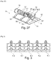
- the front of the 100 two-way connector as it is finally assembled is shown in figure 8 .
- the connector 100 obtained therefore has individualized electromagnetic shielding by unitary contact 9.1, 9.2 and an overall fluid seal at the level of the housing 90.
- the crimping parts 51, 52 are raised relative to the plane of the support frame 50. This allows the cable to be inserted without being hindered by this support frame 50.
- the figures 12A to 12G show the different steps of an alternative method of assembling a two-way connector 100 integrating two wired individual contacts obtained from a subassembly according to the first alternative of the invention.
- Step vii'1/ The mounting of at least one shielding envelope 80 surrounding the rear part 52 is then carried out with the fins 59.1, 59.2, 59.3 crimped ( Figures 12C, 12D ) then that of a shielding envelope 81 surrounding both the electrical insulating part 3 and the crimped front part 51 ( figures 12E , 12F ), so as to obtain a unitary shielded contact 9.
- Stage viii'1/ Two half-shells 93, 94 of the interface box are then mounted around two individual shielded contacts 9.1, 9.2 according to stage vii'1/( figure 12G ).
- the connector 100 obtained according to this alternative mode and represented on the picture 12H therefore has individualized electromagnetic shielding per unitary contact 9.1, 9.2 and also individualized fluid sealing per unitary contact 9.1, 9.2. shielding electromagnetic of this connector can be more efficient than that obtained with individual contacts 9 represented in figure 6F .
- the figure 13 represents an alternative mode of connector 100 from unitary unshielded contacts 9'1, 9'2 like that 9' illustrated in figure 12B , obtained from a subset according to the first alternative of the invention.
- Steps i1/ to v1/ are not described here, which remain identical to those previously described except that the seal 7 is fitted around the inner sheath 13, a pair of crimping fins 59.2 then being folded over beforehand around joint 7 ( figures 12A and 12B ).
- Step vi"1 / The central contact crimped around the conductive wire(s) is fitted into the electrical insulating part (3) to obtain their final assembly and the fins 59.3 are crimped on the insulator 3 to maintain the whole.
- Step vii" 1/ Two shielding half-shells 82, 83 are mounted covering both the electrical insulating part 3 and the crimped front part 51 as well as the crimped fins 59.3, 59.2 and 59.1 ( figure 13 ).
- Stage viii"1/ Two half-shells 93, 94 of the interface box are assembled around the unshielded contacts 9'1, 9'2 according to stage vii"1/.
- two support half-shells 95, 96 can be inserted, each inserted between the two unitary contacts 9'1, 9'2 and a shielding half-shell 82, 83 ( figure 13 ) to withstand and take up the forces which may be exerted on the sub-assemblies 9 .
- the connector 100 obtained according to this other alternative mode therefore has overall electromagnetic shielding for the two unitary contacts 9'1, 9'2 and individualized fluid sealing per unitary contact 9'1, 9'2.
- the figure 14 shows an alternative embodiment of a two-way connector housing.
- Projecting reliefs 930 can be integrated inside the case to support the front of the sub-assembly 9′ typically resting against the crimped fins 57 or shaft 56. These positioning reliefs replace the support half-shells 95, 96.
- One or more metallic reliefs 831 can also be integrated into shields 82 and 83 to ensure electrical continuity with the shield(s) of contact(s) 9'1, 9'2.
- the one-piece metal blank 5 according to the first alternative of the invention is produced by a technique of cutting, preferably rolled from a continuous strip and then assembled by crimping to the subassembly consisting of a central contact 2 preassembled in an electrically insulating part 3, it is also possible to consider other techniques for producing a connector subassembly.
- the fasteners 53 of the front part 51 are each provided at their free end with a flexible hook 531 which snaps into an eyelet 32 projecting from the periphery of the electrical insulating body 30.
- the fasteners 53 of the front part 51 are each provided at their free end with a harpoon 532 which is harpooned in an eyelet 32 projecting from the periphery of the electrical insulating body 30.
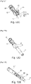
- Step 1/ A central contact 2 is preassembled. To do this, a part forming a socket 21 with petals, made of electrically conductive material, is fitted and crimped in a cylindrical body 20, electrically conductive ( figure 18A , 18B ). The crimping operation can be replaced by a snapping operation.
- the sleeve 21 is extended at the rear by a generally U-shaped front crimping part comprising a receiving barrel 22 and two crimping fins 23 connected to the barrel 22, preferably being symmetrical on either side of the barrel . These crimping fins 23 are intended to receive and to be crimped around the conductor(s) 10 of the cable 1.
- a protrusion of material 24 is provided in the rear extension of the receiving barrel 22. This protrusion of material 24 forms an assembly junction part, as detailed below.
- Step 2/ A metal crimp rear part 4 is provided for assembly with the central contact sub-assembly 2 ( Fig. 18C ).
- This crimping part 4 is made by a cut-out technique, preferably rolled from a continuous strip.
- the material and/or the thickness of this rear crimping part 4 is different from that of the sleeve 21.
- This rear crimping part 4 comprising a receiving barrel 40 and at least one crimping fin 41 connected to the barrel 40 adapted to be crimped around the shield braid 12 of the insulated cable 1.
- the rear crimping part 4 also comprises at least one crimping fin 42 adapted to be crimped around a seal 7. In the case where the seal is not required, the seal is not necessary and the crimping fin 42 is crimped directly around the outer sheath of the cable.
- the rear crimping part 4 is continuous to guarantee electrical ground continuity.
- This rear crimping part 4 further comprises a protrusion of material 43 provided in the front extension of the receiving barrel 40.
- Step 3/ Position the rear crimping part 4 opposite the front crimping part 22, 23 formed in the sleeve 21 ( Fig. 18C ). More precisely, the positioning is carried out so that the two protrusions of material 24, 43 are in contact with each other.
- the assembly can also be carried out by a technique of riveting, clinching, brazing or gluing between the two protrusions 24, 43 to be adapted according to the technique chosen.
- a 2′ subset is obtained here.
- Step 4/ We then fit and fix the central contact 2 of the sub-assembly 2′ preassembled in an electrical insulating part 3 ( figure 18D ) . More specifically, this assembly is made so as to have the cylindrical body 20 completely housed and fixed inside a cylindrical body 30 electrically insulating and the crimping part 22, 23 which projects at the rear of the insulating body 30 , delimited by a cylindrical bearing portion 31, as detailed below ( Figure 18E ).
- This step 4/ of adding an electrical insulating part is optional. It can also occur after stage 1/ or stage 2/.
- a pre-assembled connector sub-assembly 6' is then ready.
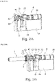
- a continuous carrier strip 44 can be produced from a plurality of unitary sub-assemblies 2'1 to 2'5 or 6'1 to 6'5 which are adjacent and therefore mechanically connected to each other by this carrier strip 44 ( figures 19, 20 ).
- the width L which defines the pitch between two adjacent sub-assemblies 6' or 2', can be adjusted as needed. By decreasing it, the density of the sub-assemblies in the coil is increased, that is to say the number of sub-assemblies that the same coil 61 can carry.
- the carrier strip 44 can be arranged outside each unitary sub-assembly 6' and secured to the rear crimping part 4.
- a pilot hole 45 is drilled directly opposite the barrel 40.
- Additional holes 45 may be drilled at other locations in carrier strip 44 ( figure 22 ).
- the continuous strip can take the form of a continuous reel 61 wound around a mandrel ( figure 23 ).
- This coil 61 can be made entirely in an assembly unit independent of an assembly unit with a cable 1.
- Step 1/ A seal 7 is fitted around the outer sheath 11 of the cable 1 ( figure 24A ) to avoid any potential damage to the metal braid 12, the conductor(s) 10 or the seal 7 itself.
- Step 2/ The outer sheath 11, the inner sheath 13 are respectively pre-stripped to reveal the conductor(s) 10 and the metal braid 12 over a predetermined length ( figure 24B ).
- step 2/ can be performed before step 1/.
- Step 3/ Remove the bare part of the inner sheath 13 of the cable 1 ( figure 24C ).
- Step i2/ A cable 1 prepared according to the figures 24A to 24C .
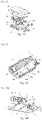
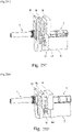
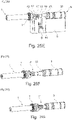
- Step ii2/ A pre-assembled sub-assembly 2' or 6' secured to the coil 61 is provided by the carrier strip 44 which is placed on a crimping support S.
- the crimping support S supports at least the barrel 22 and 40 of the front and rear crimping parts and preferably also the cylindrical body 30 electrically insulating ( figure 25A ).
- This crimping support S advantageously has cylindrical portions which hug the barrels 22, 40 of the front and rear crimping parts respectively of the preassembled sub-assembly 2' or 5.
- a mechanical cutting tool D for the carrier strip 44 is positioned around the latter ( figure 25A ).
- Step iii2/ The cable 1 provided with the seal 7 is positioned in the sub-assembly 2′ or 6′ so that the stripped part 10 of the conductive wire(s) 1 comes to be housed in the front part crimping 22, 23 of the pre-assembled central contact 2' or 6' and that the stripped part of the shielding braid 12 and the seal 7 come to be housed in the barrel 40 of the rear crimping part 4 of the sub-assembly 2' or 6' ( figure 25B ).
- Step iii′2/ The jaws M are brought as close as possible, preferably in contact with the crimping fins 23, 41, 42, in order to avoid their rotation when cutting the carrier strip. Then the carrying strip 44 is cut, which is obtained by shearing by lowering the cutting tool D (arrow of the figure 25C ), once the cable has been positioned.
- Step iv2/ The crimping is then carried out, by means of a tool of the crimping jaw-support type (M/S), on the one hand of the front crimping part 22, 23 of the central contact preassembled on the ) wire(s) conductor(s) 10 and, on the other hand, of the rear part of crimping 4 of the sub-assembly on the shielding braid 12 and on the seal 7 ( figure 25D ).
- M/S crimping jaw-support type
- the jaws M simultaneously fold the pair of crimping fins 23 around the conductor(s) 10 and each of the two pairs of crimping fins 41 and 42 respectively around the metallic shielding braid 12 and the seal 7.
- the crimping jaws M are advantageously sized to be robust, and therefore crimp cables 1 of large section, in particular power cables.
- Step v2/ To finalize the wired unitary contact 9', the electrical insulating part 3 is pushed into its final position of use ( Figure 25G ).
- Step vi2/ The mounting of at least one shielding envelope 8 surrounding both the electrical insulating part 3 and the crimped parts is then carried out, so as to obtain a unitary shielded contact 9 ( figures 25H ).
- the central contact 2 is of the female type and is made from two separate parts 20 and 21. It is possible to envisage making a central contact of the male type and a central contact in a single piece.
Landscapes
- Engineering & Computer Science (AREA)
- Manufacturing & Machinery (AREA)
- Details Of Connecting Devices For Male And Female Coupling (AREA)
- Manufacturing Of Electrical Connectors (AREA)
- Multi-Conductor Connections (AREA)
Abstract
Ebauche monobloc métallique d'assemblage par sertissage d'un connecteur à un câble isolé, sous-ensemble de connecteur préassemblé intégrant l'ébauche ou comprenant un contact central et deux parties de sertissage de matière et/ou épaisseur différente(s), procédés d'assemblage d'un connecteur à un câble associés.Une première alternative de l'invention consiste en premier lieu à définir une ébauche métallique monobloc qui va permettre de réaliser un sous-ensemble de connecteur prêt à être directement serti à un câble blindé et isolé, préalablement préparé.Une deuxième alternative de l'invention consiste en premier lieu à définir un sous-ensemble préassemblé de connecteur qui intègre des parties de sertissage avant et arrière de caractéristiques électriques et/ou mécaniques différentes, et qui est prêt à être directement serti à un câble blindé et isolé, préalablement préparé.L'une ou l'autre des deux alternatives permet de minimiser les étapes d'assemblage et les risques associés comme ceux liés aux process d'enfilage de multitudes de composants selon l'état de l'art.One-piece metallic blank for assembly by crimping of a connector to an insulated cable, pre-assembled connector sub-assembly integrating the blank or comprising a central contact and two crimping parts of different material and/or thickness(es), methods of assembly of a connector to an associated cable. A first alternative of the invention consists first of all in defining a one-piece metal blank which will make it possible to produce a connector subassembly ready to be directly crimped to a shielded and insulated cable , previously prepared. A second alternative of the invention consists firstly in defining a preassembled connector subassembly which integrates front and rear crimping parts with different electrical and/or mechanical characteristics, and which is ready to be directly crimped to a shielded and insulated cable, previously prepared. Either of the two alternatives makes it possible to minimize the assembly steps and the associated risks such as c them linked to the process of threading multitudes of components according to the state of the art.
Description
La présente invention concerne le domaine des connecteurs électriques.The present invention relates to the field of electrical connectors.
L'invention vise notamment à améliorer l'assemblage d'un connecteur à un câble isolé, en particulier d'un connecteur de puissance à un câble à forte section pour le passage de courants élevés.The invention aims in particular to improve the assembly of a connector to an insulated cable, in particular of a power connector to a cable with a large section for the passage of high currents.
Il peut s'agir de connecteurs de puissance reliant par exemple la batterie d'un véhicule au moteur électrique ou à l'électronique de puissance.They may be power connectors connecting, for example, the battery of a vehicle to the electric motor or to the power electronics.
Il peut s'agir de connecteurs véhiculant d'autres types de signaux, comme des signaux RF, ou des données.These may be connectors conveying other types of signals, such as RF signals, or data.
Bien que décrite en référence à une application privilégiée, la connectique pour véhicule automobile, et plus particulièrement, pour véhicules hybrides et électriques, l'invention peut être mise en œuvre dans toute autre application.Although described with reference to a preferred application, connectors for motor vehicles, and more particularly, for hybrid and electric vehicles, the invention can be implemented in any other application.
Le fort développement des véhicules hybrides et électriques nécessite des solutions fiables et aisées à mettre en œuvre en particulier pour réaliser des liaisons entre câble blindé et connecteurs de puissance, soit pour les équipementiers, soit par les constructeurs de véhicules eux-mêmes.The strong development of hybrid and electric vehicles requires reliable and easy-to-implement solutions, in particular for making connections between shielded cables and power connectors, either for equipment manufacturers or by the vehicle manufacturers themselves.
Plusieurs connecteurs ont ainsi été proposés.Several connectors have thus been proposed.
On peut citer ici les connecteurs à deux voies commercialisés par les sociétés Tyco Electronics Connectivity sous la dénomination commerciale « gamme HVP-800 », Aptiv sous la dénomination « gamme RCS800 » ou encore Rosenberger sous la dénomination « gamme HVR200 ».Mention may be made here of the two-way connectors marketed by the companies Tyco Electronics Connectivity under the trade name “HVP-800 range”, Aptiv under the name “RCS800 range” or even Rosenberger under the name “HVR200 range”.
Tous les assemblages des différents composants (contacts, câble blindé, connecteur) avec ces connecteurs existants doivent se faire en plusieurs étapes successives et ordonnées, avec un sens précis de montage.All the assemblies of the various components (contacts, shielded cable, connector) with these existing connectors must be done in several successive and orderly steps, with a precise direction of assembly.
Le risque d'oubli d'une pièce et/ou d'erreur de sens ou d'ordre de montage est élevé et génère des mises au rebut des connecteurs mal assemblés avec un câble.The risk of forgetting a part and/or making an error in the direction or assembly order is high and generates scrapping of poorly assembled connectors with a cable.
En outre, avec les connecteurs existants, l'assemblage en automatique est complexe voire impossible à mettre en œuvre.In addition, with existing connectors, automatic assembly is complex or even impossible to implement.
Par exemple, si on se réfère à un connecteur deux voies de la gamme HVP-800 précitée, l'assemblage doit être réalisé par un enfilage successif des différents composants (pièce de retenue, joint, férules interne et externe, isolant électrique, cage de protection du contact central, bague de blindage électromagnétique) du connecteur sur un câble, avec sertissage à chaque étape de montage d'un composant conducteur électrique (contact).For example, if we refer to a two-way connector from the aforementioned HVP-800 range, the assembly must be carried out by successively threading the various components (retaining part, gasket, internal and external ferrules, electrical insulator, protection of the central contact, electromagnetic shielding ring) of the connector on a cable, with crimping at each assembly stage of an electrically conductive component (contact).
Par conséquent, il existe un besoin d'améliorer les assemblages de connecteurs, en particulier de connecteurs de puissance, à un câble blindé, notamment en vue de pallier les inconvénients précitésConsequently, there is a need to improve the assemblies of connectors, in particular of power connectors, to a shielded cable, in particular with a view to overcoming the aforementioned drawbacks
L'invention vise à répondre à tout ou partie de ce besoin.The invention aims to meet all or part of this need.
Pour ce faire, l'invention a pour objet, selon l'un de ses aspects, et selon une première alternative, une ébauche monobloc métallique d'assemblage par sertissage d'un connecteur à un câble, comprenant :
- une bande périphérique formant un support de préférence plan qui s'étend selon un axe longitudinal;
- au moins deux parties alignées qui s'étendent chacune le long de l'axe longitudinal en étant séparées l'une de l'autre, chacune des deux parties étant maintenue au support par au moins une lame formant une attache, la partie avant étant une partie de sertissage, de clipsage, de montage en force par harponnage ou de surmoulage, adaptée pour recevoir et maintenir respectivement par sertissage, clipsage, montage en force par harponnage ou surmoulage un composant électrique du connecteur, tandis que la partie arrière de préférence continue est une partie de sertissage sur le câble, comprenant des ajours destinés à assurer le passage de mâchoires de sertissage.
- a peripheral strip forming a preferably planar support which extends along a longitudinal axis;
- at least two aligned parts which each extend along the longitudinal axis while being separated from each other, each of the two parts being held to the support by at least one blade forming a clip, the front part being a part for crimping, clipping, force-fitting by harpooning or overmoulding, adapted to receive and hold respectively by crimping, clipping, force-fitting by harpooning or overmoulding an electrical component of the connector, while the preferably continuous rear part is a crimping part on the cable, comprising openings intended to ensure the passage of crimping jaws.
Selon un mode de réalisation avantageux, la partie avant est une partie de sertissage.According to an advantageous embodiment, the front part is a crimping part.
Selon ce mode, chacune des deux parties de sertissage comprend avantageusement un fût de réception et au moins une ailette de sertissage reliée au fût, l'un des fûts étant destiné à recevoir le composant électrique du connecteur.According to this mode, each of the two crimping parts advantageously comprises a receiving barrel and at least one crimping fin connected to the barrel, one of the barrels being intended to receive the electrical component of the connector.
Selon un mode de réalisation, l'ébauche monobloc comprend au moins une lame d'appui, reliée au support et qui s'étend à l'intérieur de celui-ci entre les deux parties de sertissage de sorte à former une zone d'appui d'un composant électrique du connecteur reçu dans l'une des deux parties de sertissage.According to one embodiment, the one-piece blank comprises at least one support blade, connected to the support and which extends inside the latter between the two crimping parts so as to form a support zone of an electrical component of the connector received in one of the two crimping parts.
Avantageusement, la partie avant de sertissage comprend au moins une ailette de sertissage adaptée pour être sertie autour du composant électrique, de préférence autour d'une pièce isolant électrique logeant un contact central préassemblé.Advantageously, the front crimping part comprises at least one crimping fin adapted to be crimped around the electrical component, preferably around an electrical insulating part housing a preassembled central contact.
La partie arrière de sertissage comprend de préférence au moins une ailette de sertissage adaptée pour être sertie autour de la tresse de blindage du câble isolé.The rear crimping part preferably comprises at least one crimping fin adapted to be crimped around the shield braid of the insulated cable.
La partie arrière de sertissage peut comprendre au moins une ailette de sertissage adaptée pour être sertie autour de la gaine d'isolation extérieure et/ou intérieure du câble isolé ou autour d'un joint d'étanchéité emmanché autour de la gaine extérieure du câble isolé.The rear crimping part may comprise at least one crimping fin adapted to be crimped around the outer and/or inner insulation sheath of the insulated cable or around a seal fitted around the outer sheath of the insulated cable .
Avantageusement, la partie arrière de sertissage est continue.Advantageously, the rear crimping part is continuous.
Chacune des deux parties est de préférence maintenue au support par au moins une attache qui s'étend selon l'axe longitudinal (X) et/ou latéralement à celui-ci.Each of the two parts is preferably held to the support by at least one fastener which extends along the longitudinal axis (X) and/or laterally thereto.
L'invention a pour objet, selon un autre de ses aspects, un sous-ensemble de connecteur, comprenant :
- un composant électrique comprenant un contact central préassemblé, le cas échéant, logé dans une pièce isolante électrique,
- une ébauche monobloc telle que décrite précédemment, dont une des deux parties reçoit le composant électrique.
- an electrical component comprising a pre-assembled central contact, if necessary, housed in an electrical insulating part,
- a one-piece blank as described above, one of the two parts of which receives the electrical component.
Avantageusement, le composant électrique est serti sur l'ébauche monobloc par la partie avant.Advantageously, the electrical component is crimped onto the one-piece blank via the front part.
L'invention concerne aussi une bobine pour l'assemblage automatique ou semi-automatique par sertissage d'un connecteur à un câble, comprenant une pluralité de sous-ensembles comme ci-dessus, jointifs par un bord des supports des ébauches et enroulés autour d'un mandrin.The invention also relates to a reel for the automatic or semi-automatic assembly by crimping of a connector to a cable, comprising a plurality of sub-assemblies as above, joined by one edge of the supports of the blanks and wound around a mandrel.
L'invention concerne également un procédé d'assemblage d'au moins un connecteur à un câble comprenant les étapes suivantes :
- i1/ fourniture d'un câble blindé et isolé, le(s) fil(s) conducteur(s) et la tresse de blindage étant dénudés à une extrémité du câble;
- ii1/ fourniture d'un sous-ensemble comme ci-avant, de préférence à partir d'une bobine décrite ci-avant;
- iii1/ positionnement du câble dans le sous-ensemble de sorte que la partie dénudée du(des) fil(s) conducteur(s) vienne se loger dans la partie arrière de sertissage du contact central préassemblé et que la partie dénudée de la tresse de blindage vienne se loger dans la partie de sertissage du sous-ensemble qui est séparée du contact central ;
- iv1/ sertissage, au moyen d'un outil de sertissage de type mâchoires-enclume (M), inséré dans les ajours entre support et attache(s) et lame(s) d'appui, de la partie arrière de sertissage du contact central préassemblé sur le(les) fil(s) conducteur(s) et, de préférence simultanément, de la partie de sertissage du sous-ensemble sur la tresse de blindage;
- v1/ découpe de l'(des) attache(s), de sorte à obtenir un contact unitaire préassemblé avec le câble.
- i1/ supply of a shielded and insulated cable, the conductive wire(s) and the shielding braid being stripped at one end of the cable;
- ii1/ supply of a subassembly as above, preferably from a coil described above;
- iii1/ positioning of the cable in the sub-assembly so that the bare part of the conductor wire(s) is housed in the rear crimping part of the pre-assembled central contact and the bare part of the shield is housed in the crimping part of the sub-assembly which is separated from the central contact;
- iv1/ crimping, by means of a jaw-anvil type crimping tool (M), inserted in the openings between the support and the attachment(s) and the support blade(s), of the rear crimping part of the central contact pre-assembled on the conductive wire(s) and, preferably simultaneously, of the crimping part of the sub-assembly on the shield braid;
- v1/ cutting of the clip(s), so as to obtain a pre-assembled single contact with the cable.
Selon une variante avantageuse, l'étape i1/ comprend en outre la fourniture d'un joint d'étanchéité emmanché autour de la gaine extérieure ou intérieure du câble, l'étape iv/ comprenant en outre le sertissage de la partie arrière du sous-ensemble, de préférence simultanément à son sertissage sur la tresse de blindage, sur le joint d'étanchéité.According to an advantageous variant, step i1/ further comprises supplying a seal fitted around the outer or inner sheath of the cable, step iv/ further comprising crimping the rear part of the sub- together, preferably simultaneously with its crimping on the shielding braid, on the seal.
De préférence, l'étape v1/ est une découpe mécanique au moyen d'une lame ou une découpe mécanique en cisaillement ou une découpe par laser.Preferably, step v1/ is a mechanical cut using a blade or a mechanical shear cut or a laser cut.
Selon le mode de réalisation avantageux, le procédé comprend après l'étape v/ de découpe, l'étape suivante:
vi1/ emmanchement du contact central serti autour du(des) fil(s) conducteur(s) dans la pièce isolante électrique (3) pour obtenir leur assemblage définitif.According to the advantageous embodiment, the method comprises after step v/ cutting, the following step:
vi1/fitting of the central contact crimped around the conductive wire(s) in the electrical insulating part (3) to obtain their final assembly.
Selon un autre mode de réalisation avantageux, le procédé comprend, après l'étape vi1/, lorsque le joint d'étanchéité est emmanché autour de la gaine extérieure du câble, les étapes suivantes:
- vii1/ montage par encliquetage d'au moins une enveloppe de blindage entourant à la fois la pièce isolante électrique et la partie avant, de sorte à obtenir un contact unitaire blindé ;
- viiil/ montage d'au moins un contact unitaire câblé blindé selon l'étape viil/, dans un boîtier monobloc de connecteur, avec de préférence maintien du contact unitaire par des brides de rétention à l'arrière du connecteur.
- vii1/ mounting by snap-fitting of at least one shielding casing surrounding both the electrical insulating part and the front part, so as to obtain a unitary shielded contact;
- viiil/ assembly of at least one shielded wired unitary contact according to step viil/, in a one-piece connector housing, preferably with maintenance of the unitary contact by retention flanges at the rear of the connector.
Selon encore un autre mode de réalisation avantageux, le procédé comprend, après l'étape vi1/,lorsque le joint d'étanchéité est emmanché autour de la gaine intérieure du câble et de préférence autour de la tresse du câble, les étapes suivantes :
- vii'1/ montage d'au moins une enveloppe de blindage entourant la partie arrière sertie et d'une enveloppe de blindage entourant à la fois la pièce isolante électrique et la partie avant, de sorte à obtenir un contact unitaire blindé;
- viii'1/ montage de deux demi-coquilles de boîtier d'interface autour du(des) contact(s) unitaire(s) blindé(s) selon l'étape vii"1/, avec de préférence maintien du contact unitaire par des brides de rétention à l'arrière du connecteur.
- vii'1/ assembly of at least one shielding casing surrounding the rear crimped part and of a shielding casing surrounding both the electrical insulating part and the front part, so as to obtain a unitary shielded contact;
- viii'1/ assembly of two interface box half-shells around the shielded unitary contact(s) according to step vii"1/, preferably with the unitary contact maintained by retention flanges on the back of the connector.
Selon un autre mode de réalisation avantageux, le procédé comprend, après l'étape vi1/, lorsque le joint d'étanchéité est emmanché autour de la gaine intérieure du câble, les étapes suivantes :
- vii"1/ montage de deux demi-coquilles de blindage recouvrant les contacts unitaires ;
- viii" 1/ montage de deux demi-coquilles de boitier d'interface autour des deux demi-coquilles de blindage selon l'étape vii" 1/.
- vii"1/ assembly of two shielding half-shells covering the individual contacts;
- viii" 1/ assembly of two interface box half-shells around the two shielding half-shells according to step vii" 1/.
L'invention a encore pour objet un contact unitaire câblé, le cas échéant blindé obtenu par le procédé précédemment décrit.Another subject of the invention is a wired unitary contact, if necessary shielded, obtained by the process described above.
L'invention a enfin pour objet un connecteur, notamment connecteur multivoies, obtenu par le procédé précédemment décrit.Finally, the subject of the invention is a connector, in particular a multiway connector, obtained by the process described above.
Ainsi, l'invention selon cette première alternative consiste en premier lieu à définir une ébauche métallique monobloc qui va permettre de réaliser un sous-ensemble de connecteur prêt à être directement serti à un câble blindé et isolé, préalablement préparé, qui permet de minimiser les étapes d'assemblage et les risques associés comme ceux liés aux process d'enfilage de multitudes de composants selon l'état de l'art.Thus, the invention according to this first alternative consists in the first place in defining a one-piece metal blank which will make it possible to produce a connector subassembly ready to be directly crimped to a shielded and insulated cable, prepared beforehand, which makes it possible to minimize the assembly steps and the associated risks such as those linked to the process of threading multitudes of components according to the state of the art.
L'invention a également pour objet, selon une deuxième alternative de l'invention un sous-ensemble préassemblé conducteur électrique et qui s'étend selon un axe longitudinal (X), à assembler par sertissage sur un câble comprenant une âme électriquement conductrice et au moins une gaine isolante électrique et, le cas échéant une tresse de blindage autour de l'âme, le sous-ensemble comprenant un contact central et comprenant au moins deux parties de sertissage, conductrices électriques, dans le prolongement axial du corps cylindrique dont la partie la plus proche du corps, dite partie avant, est adaptée pour être sertie autour de l'âme du câble, tandis que la partie la plus éloignée du corps, dite partie arrière est adaptée pour être sertie autour de la gaine isolante et/ou le cas échéant autour de la tresse de blindage, les parties avant et arrière de sertissage étant de matière constitutive et/ou d'épaisseur différente(s).The invention also relates, according to a second alternative of the invention, to a preassembled electrically conductive subassembly which extends along a longitudinal axis (X), to be assembled by crimping on a cable comprising an electrically conductive core and at the at least one electrically insulating sheath and, where applicable, a shielding braid around the core, the subassembly comprising a central contact and comprising at least two crimping parts, electrically conductive, in the axial extension of the cylindrical body, the part of which the part closest to the body, called the front part, is adapted to be crimped around the core of the cable, while the part farthest from the body, called the rear part, is adapted to be crimped around the insulating sheath and/or the where appropriate around the shielding braid, the front and rear crimping parts being of different constituent material and/or thickness.
Selon un mode de réalisation, les parties avant et arrière de sertissage étant de matière constitutive différente et jointes par une jonction électriquement conductrice ou isolante. On peut ainsi différencier la nature des matériaux en fonction de la partie d'un câble à sertir : l'âme étant directement soumise au passage du courant, notamment de puissance, la partie avant de sertissage peut être en un matériau de grande conductivité, tandis que la tresse métallique servant uniquement de blindage électromagnétique, la partie arrière de sertissage peut être en un matériau de moindre conductivité. On peut aussi prévoir une partie arrière isolante électriquement.According to one embodiment, the front and rear crimping parts being of different constituent material and joined by an electrically conductive or insulating junction. It is thus possible to differentiate the nature of the materials according to the part of a cable to be crimped: the core being directly subjected to the passage of current, in particular of power, the front part of crimping can be in a material of high conductivity, while that the metal braid only serving as electromagnetic shielding, the rear crimping part can be made of a material of lower conductivity. It is also possible to provide an electrically insulating rear part.
Autrement dit, on peut réaliser une partie arrière de sertissage de plus faible épaisseur et/ou conductivité moindre pour des courants faibles et pour un sertissage sur un diamètre plus grand, on peut adapter ses caractéristiques mécaniques à souhait. On peut donc sélectionner les matériaux ou épaisseurs en fonction de leurs propriétés mécaniques et électriques pour chaque partie de sertissage de façon indépendante et, ainsi réduire les coûts.In other words, it is possible to produce a rear crimping part of smaller thickness and/or less conductivity for low currents and for crimping over a larger diameter, its mechanical characteristics can be adapted as desired. It is therefore possible to select the materials or thicknesses according to their mechanical and electrical properties for each crimping part independently and thus reduce costs.
De préférence, la jonction est formée par rivetage, clinchage, brasage ou soudure ou collage.Preferably, the junction is formed by riveting, clinching, brazing or welding or gluing.
Avantageusement, la partie arrière de sertissage est continue.Advantageously, the rear crimping part is continuous.
Selon un mode de réalisation avantageux, chacune des deux parties de sertissage comprend au moins un fût de réception et au moins une ailette de sertissage reliée au fût, le fût de la partie avant de sertissage étant destiné à recevoir l'âme du câble tandis que le fût de la partie arrière de sertissage est destiné à recevoir la gaine isolante et/ou la tresse du câble.According to an advantageous embodiment, each of the two crimping parts comprises at least one receiving barrel and at least one crimping fin connected to the barrel, the barrel of the front crimping part being intended to receive the core of the cable while the barrel of the rear crimping part is intended to receive the insulating sheath and/or the braid of the cable.
Selon une variante de réalisation avantageuse, la partie arrière de sertissage comprend au moins une ailette de sertissage adaptée pour être sertie autour de la gaine d'isolation extérieure et/ou intérieure du câble isolé ou autour d'un joint d'étanchéité emmanché autour de la gaine extérieure du câble isolé.According to an advantageous variant embodiment, the rear crimping part comprises at least one crimping fin adapted to be crimped around the outer and/or inner insulation sheath of the insulated cable or around a seal fitted around the outer sheath of the insulated cable.
Selon cette variante, la partie arrière de sertissage comprend avantageusement au moins une ailette de sertissage adaptée pour être sertie autour de la tresse de blindage du câble.According to this variant, the rear crimping part advantageously comprises at least one crimping fin adapted to be crimped around the shielding braid of the cable.
De préférence, le contact central préassemblé comprend une pièce isolante électrique dans lequel est logé le corps électriquement conducteur.Preferably, the preassembled central contact comprises an electrically insulating part in which the electrically conductive body is housed.
L'invention concerne aussi une bobine pour l'assemblage automatique ou semi-automatique par sertissage d'un connecteur à un câble, comprenant une pluralité de sous-ensembles selon la deuxième alternative de l'invention comme ci-dessus, reliés mécaniquement entre eux par au moins une bande porteuse et enroulés autour d'un mandrin.The invention also relates to a coil for the automatic or semi-automatic assembly by crimping of a connector to a cable, comprising a plurality of sub-assemblies according to the second alternative of the invention as above, mechanically connected together by at least one carrying strip and wound around a mandrel.
Avantageusement, la bande porteuse est mécaniquement reliée ou intégrée à la partie avant ou arrière de sertissage ou le cas échéant reliée à la jonction entre parties avant et arrière.Advantageously, the carrier strip is mechanically connected or integrated into the front or rear crimping part or, where appropriate, connected to the junction between the front and rear parts.
Avantageusement encore, la bande porteuse est percée d'une pluralité de trous de guidage pour guider la bande porteuse lors du défilement de la bobine.Advantageously again, the carrier strip is pierced with a plurality of guide holes to guide the carrier strip during the scrolling of the reel.
L'invention concerne également un procédé d'assemblage d'au moins un connecteur à un câble comprenant les étapes suivantes :
- i2/ fourniture d'un câble blindé et isolé, le(s) fil(s) conducteur(s) et la tresse de blindage étant dénudés à une extrémité du câble;
- ii2/ fourniture d'un sous-ensemble comme ci-avant, de préférence à partir d'une bobine décrite ci-avant;
- iii2/ positionnement du câble dans le sous-ensemble préassemblé de sorte que la partie dénudée du(des) fil(s) conducteur(s) vienne se loger dans la partie avant de sertissage du contact central préassemblé et que la partie dénudée de la tresse de blindage vienne se loger dans la partie arrière de sertissage du sous-ensemble;
- iv2/ sertissage de la partie avant de sertissage du contact central préassemblé sur le(les) fil(s) conducteur(s) et, de préférence simultanément, de la partie arrière de sertissage du contact central préassemblé sur la tresse de blindage, de sorte à obtenir un contact unitaire préassemblé avec le câble.
- i2/ supply of a shielded and insulated cable, the conductive wire(s) and the shielding braid being stripped at one end of the cable;
- ii2/ supply of a sub-assembly as above, preferably from a coil described above;
- iii2/ positioning of the cable in the pre-assembled sub-assembly so that the stripped part of the conductor wire(s) is housed in the front crimping part of the pre-assembled central contact and the stripped part of the braid of shielding is housed in the rear crimping part of the sub-assembly;
- iv2/ crimping the front crimping part of the pre-assembled central contact on the conductive wire(s) and, preferably simultaneously, the rear crimping part of the pre-assembled central contact on the shielding braid, so to obtain a unitary contact preassembled with the cable.
Avantageusement, le procédé comprend, lorsque l'étape ii2/ est réalisée à partir de la bobine, une étape iii'2/ de découpe de la bande porteuse, le cas échéant simultanément à l'étape iii2/ de positionnement du câble.Advantageously, the method comprises, when step ii2/ is carried out from the reel, a step iii′2/ of cutting out the carrier strip, if necessary simultaneously with step iii2/ of positioning the cable.
L'étape iii'2/ est de préférence une découpe mécanique de la bande porteuse au moyen d'une lame ou une découpe mécanique en cisaillement ou une découpe par laser.Step iii′2/ is preferably mechanical cutting of the carrier strip by means of a blade or mechanical shear cutting or laser cutting.
Selon une variante de réalisation, l'étape iv2/ est réalisée avec au moins une partie du sous-ensemble préassemblé posée sur un support de sertissage.According to a variant embodiment, step iv2/ is carried out with at least part of the pre-assembled sub-assembly placed on a crimping support.
Selon une variante avantageuse, l'étape i2/ comprend en outre la fourniture d'un joint d'étanchéité emmanché autour de la gaine extérieure ou intérieure du câble, l'étape iv2/ comprenant en outre le sertissage de la partie arrière du sous-ensemble, de préférence simultanément à son sertissage sur la tresse de blindage, sur le joint d'étanchéité.According to an advantageous variant, step i2/ further comprises the supply of a seal fitted around the outer or inner sheath of the cable, step iv2/ further comprising the crimping of the rear part of the sub- together, preferably simultaneously with its crimping on the shielding braid, on the seal.
L'invention a encore pour objet un contact unitaire câblé, le cas échéant blindé obtenu par le procédé précédemment décrit.Another subject of the invention is a wired unitary contact, if necessary shielded, obtained by the process described above.
Ainsi, l'invention selon la deuxième alternative consiste en premier lieu à définir un sous-ensemble préassemblé de connecteur qui intègre des parties de sertissage avant et arrière de caractéristiques électriques et/ou mécaniques différentes, et qui est prêt à être directement serti à un câble blindé et isolé, préalablement préparé, qui permet de minimiser les étapes d'assemblage et les risques associés comme ceux liés aux process d'enfilage de multitudes de composants selon l'état de l'art.Thus, the invention according to the second alternative consists in the first place in defining a preassembled connector sub-assembly which integrates front and rear crimping parts with different electrical and/or mechanical characteristics, and which is ready to be crimped directly to a shielded and insulated cable, prepared beforehand, which makes it possible to minimize the assembly stages and the associated risks such as those linked to the process of threading multitudes of components according to the state of the art.
Les avantages de l'invention à la fois selon la première et la deuxième alternatives sont nombreux par rapport à l'existant parmi lesquels on peut citer:
- la fabrication d'un sous-ensemble de connecteur, de préférence au sein d'une bobine continue, prêt à être assemblé par sertissage à un câble en une seule étape compatible avec la mise en œuvre d'outils de sertissage robustes (mâchoires surdimensionnées par rapport à l'état de l'art) ;
- un assemblage qui permet l'intégration aisée d'une fonction d'étanchéité par contact unitaire au sein d'un connecteur monovoie ou par connecteur multivoies ;
- un assemblage qui laisse la possibilité d'une modularité des fonctions de blindage électromagnétiques au niveau d'un contact unitaire ou au niveau d'un connecteur multivoies du contact ;
- un assemblage aisé à mettre en œuvre en automatique.
- the manufacture of a connector subassembly, preferably within a continuous coil, ready to be assembled by crimping to a cable in a single step compatible with the implementation of robust crimping tools (oversized jaws by report on the state of the art);
- an assembly which allows the easy integration of a sealing function by unitary contact within a single-channel connector or by multi-channel connector;
- an assembly which leaves the possibility of modularity of the electromagnetic shielding functions at the level of a single contact or at the level of a multiway connector of the contact;
- easy assembly to implement automatically.
En outre par rapport à la première alternative, les avantages de la solution selon la deuxième alternative de l'invention sont le gain de place et la possibilité d'utiliser moins de matière métallique lors d'un assemblage en continu, du fait de la mise en œuvre d'une simple bande porteuse, et du fait d'un pas entre deux sous-ensembles préassemblés successifs réduit, et donc un coût moindre.Furthermore, compared to the first alternative, the advantages of the solution according to the second alternative of the invention are the space saving and the possibility of using less metallic material during continuous assembly, due to the implementation of a simple carrier strip, and due to a pitch between two successive preassembled subassemblies reduced, and therefore a lower cost.
Les applications envisagées pour l'invention sont nombreuses parmi lesquelles on peut citer les connexions électriques de puissance dans les véhicules automobiles hybrides ou électriques.The applications envisaged for the invention are numerous, among which mention may be made of electrical power connections in hybrid or electric motor vehicles.
Plus généralement, l'invention peut se décliner pour différentes applications et diamètres de câbles (de 6kW à environ 300kW).More generally, the invention can be declined for different applications and cable diameters (from 6kW to about 300kW).
D'autres avantages et caractéristiques de l'invention ressortiront mieux à la lecture de la description détaillée d'exemples de mise en œuvre de l'invention faite à titre illustratif et non limitatif en référence aux figures suivantes.Other advantages and characteristics of the invention will emerge better on reading the detailed description of examples of implementation of the invention given by way of non-limiting illustration with reference to the following figures.
-
[
Fig 1 ] lafigure 1 représente un exemple de câble blindé et isolé utilisé dans les véhicules électriques.[Fig 1 ] thefigure 1 represents an example of shielded and insulated cable used in electric vehicles. -
[
Fig 2A], [Fig 2B ], [Fig 2C], [Fig 2D ], [Fig 2E ], [Fig 2F ] lesfigures 2A, 2B ,2C, 2D ,2E ,2F sont des vues en perspective montrant différentes étapes d'assemblage d'un sous-ensemble de connecteur préassemblé selon une première alternative de l'invention intégrant une ébauche monobloc.[Fig 2A], [Fig 2B ], [Fig 2C], [Fig 2D ], [Fig 2E ], [Fig 2F ] themFigures 2A, 2B ,2C, 2D ,2E ,2 F are perspective views showing different stages of assembly of a sub-assembly preassembled connector according to a first alternative of the invention incorporating a one-piece blank. -
[
Fig 3 ] lafigure 3 est une vue en perspective d'une pluralité de sous-ensembles jointifs de connecteur obtenu selon lesfigures 2A à 2F , prêts à être assemblés avec un câble blindé et isolé.[Fig.3 ] thepicture 3figures 2A to 2F , ready to be assembled with shielded and insulated cable. -
[
Fig 4 ] lafigure 4 est une vue en perspective montrant un exemple de bobine formant un kit d'assemblage prêt à être utilisé sur une ligne d'assemblage avec câble avec des sous-ensembles selon la première alternative.[Fig 4 ] thefigure 4 is a perspective view showing an example of a coil forming an assembly kit ready to be used on an assembly line with cable with sub-assemblies according to the first alternative. -
[
Fig 5A ], [Fig 5B], [Fig 5C ] lesfigures 5A ,5B, 5C sont des vues en perspective montrant les différentes étapes de préparation d'un câble blindé et isolé avant son assemblage par sertissage avec un sous-ensemble de connecteur préassemblé selon la première alternative de l'invention.[Fig 5A ], [Fig 5B], [Fig 5C ] themfigure 5A ,5B, 5C are perspective views showing the various stages of preparation of a shielded and insulated cable before its assembly by crimping with a preassembled connector subassembly according to the first alternative of the invention. -
[
Fig 6A], [Fig 6B ], [Fig 6C], [Fig 6D ], [Fig 6E ], [Fig 6F ] lesfigures 2A, 2B ,2C, 2D ,2E ,2F sont des vues en perspective montrant les différentes étapes d'assemblage d'un sous-ensemble de connecteur préassemblé selon la première alternative de l'invention avec un câble blindé et isolé préparé selon lesfigures 5A à 5C , afin d'obtenir un contact unitaire blindé et câblé.[Fig 6A], [Fig 6B ], [Fig 6C], [Fig 6D ], [Fig 6E ], [Fig 6F ] themFigures 2A, 2B ,2C, 2D ,2E ,2 F are perspective views showing the different assembly steps of a preassembled connector subassembly according to the first alternative of the invention with a shielded and insulated cable prepared according to thefigures 5A to 5C , in order to obtain a single shielded and wired contact. -
[
Fig 7A], [Fig 7B ], [Fig 7C], [Fig 7D ] lesfigures 7A, 7B ,7C, 7D sont des vues en perspective montrant les différentes étapes d'un mode d'assemblage d'un connecteur à deux voies intégrant deux contacts unitaires blindés et câblés selon lafigure 6F .[Fig 7A], [Fig 7B ], [Fig 7C], [Fig 7D ] themFigures 7A, 7B ,7C, 7D are perspective views showing the different stages of an assembly mode of a two-way connector integrating two unit contacts shielded and wired according to thefigure 6F . -
[
Fig 8 ] lafigure 8 est une vue en perspective montrant le connecteur à deux voies obtenu à l'issue de l'étape de lafigure 7D .[Fig.8 ] thefigure 8 is a perspective view showing the two-way connector obtained at the end of the step offigure 7D . -
[
Fig 9A] et [Fig 9B ] lesfigures 9A et 9B sont des vues en perspective d'une première variante de réalisation d'une ébauche monobloc pour l'assemblage par sertissage selon la première alternative de l'invention.[Fig 9A] and [Fig 9B ] themfigures 9A and 9B are perspective views of a first embodiment variant of a one-piece blank for assembly by crimping according to the first alternative of the invention. -
[
Fig 10 ] lafigure 10 est une vue en perspective d'une deuxième variante de réalisation d'une ébauche monobloc pour l'assemblage par sertissage selon la première alternative de l'invention.[Fig. 10 ] thefigure 10 is a perspective view of a second embodiment variant of a one-piece blank for assembly by crimping according to the first alternative of the invention. -
[
Fig 11 ] lafigure 11 est une vue en perspective d'une troisième variante de réalisation d'une ébauche monobloc pour l'assemblage par sertissage selon la première alternative de l'invention.[Fig.11 ] thefigure 11 is a perspective view of a third alternative embodiment of a one-piece blank for assembly by crimping according to the first alternative of the invention. -
[
Fig 12A], [Fig 12B ], [Fig 12C], [Fig 12D ], [Fig 12E ], [Fig 12F], [Fig 12G], [Fig 12H ] lesfigures 12A, 12B ,12C, 12D ,12E ,12F, 12G, 12H sont des vues en perspective montrant les différentes étapes d'un mode alternatif d'assemblage d'un connecteur à deux voies intégrant deux contacts unitaires blindés et câblés obtenus à partir d'un sous-ensemble selon la première alternative de l'invention.[Fig 12A], [Fig 12B ], [Fig 12C], [Fig 12D ], [Fig 12E ], [Fig 12F], [Fig 12G], [Fig 12H ] themFigures 12A, 12B ,12C, 12D ,12E ,12F, 12G, 12H are perspective views showing the different steps of an alternative method of assembling a two-way connector integrating two shielded and wired individual contacts obtained from a subassembly according to the first alternative of the invention. -
[
Fig 13 ] lafigure 13 est une vue en perspective montrant une étape d'un autre mode alternatif d'assemblage d'un connecteur à deux voies intégrant deux contacts unitaires câblés obtenus à partir d'un sous-ensemble selon la première alternative de l'invention.[Fig. 13 ] thefigure 13 is a perspective view showing a step of another alternative method of assembling a two-way connector integrating two wired individual contacts obtained from a subassembly according to the first alternative of the invention. -
[
Fig 14 ] lafigure 14 est une vue de variante de réalisation d'un boîtier de connecteur à deux voies selon la première alternative de l'invention.[Fig. 14 ] thefigure 14 is a view of an alternative embodiment of a two-way connector housing according to the first alternative of the invention. -
[
Fig 15A ] et [Fig 15B ] lesfigures 15A et15B sont des vues en perspective d'une variante de réalisation d'un sous-ensemble de connecteur selon la première alternative de l'invention par clipsage d'une ébauche monobloc à une pièce isolante électrique logeant un contact central préassemblé.[Fig 15A ] and [Fig. 15B ] themfigures 15A and15B are perspective views of an alternative embodiment of a connector subassembly according to the first alternative of the invention by clipping a one-piece blank to an electrical insulating part housing a preassembled central contact. -
[
Fig 16A] et [Fig 16B ] lesfigures 16A et 16B sont des vues en perspective d'une variante de réalisation d'un sous-ensemble de connecteur selon la première alternative de l'invention par montage en force avec harponnage d'une ébauche monobloc à une pièce isolante électrique logeant un contact central préassemblé.[Fig 16A] and [Fig 16B ] themfigures 16A and 16B are perspective views of an alternative embodiment of a connector sub-assembly according to the first alternative of the invention by force fitting with harpooning of a one-piece blank to an electrical insulating part housing a preassembled central contact. -
[
Fig 17A] et [Fig 17B ] lesfigures 17A et 17B sont des vues en perspective d'une variante de réalisation d'un sous-ensemble de connecteur selon la première alternative de l'invention par surmoulage d'une pièce isolante électrique.[Fig 17A] and [Fig 17B ] themfigures 17A and 17B are perspective views of an alternative embodiment of a connector subassembly according to the first alternative of the invention by overmolding an electrical insulating part. -
[
Fig 18A ], [Fig 18B], [Fig 18C], [Fig 18D ], [Fig 18E], [Fig 18F ], lesfigures 18A ,18B, 18C, 18D ,18E, 18F sont des vues en perspective montrant différentes étapes d'assemblage d'un sous-ensemble de connecteur préassemblé selon la deuxième alternative de l'invention.[Fig 18A ], [Fig 18B], [Fig 18C], [Fig 18D ], [Fig 18E], [Fig 18F ], themfigure 18A ,18B, 18C, 18D ,18E, 18F are perspective views showing different stages of assembly of a preassembled connector subassembly according to the second alternative of the invention. -
[
Fig 19 ] lafigure 19 est une vue en perspective d'une pluralité de sous-ensembles adjacents de connecteur obtenu selon lesfigures 18A à 18F , prêts à être assemblés avec un câble blindé et isolé.[Fig. 19 ] thefigure 19 is a perspective view of a plurality of adjacent connector subassemblies obtained according to thefigures 18A to 18F , ready to be assembled with shielded and insulated cable. -
[
Fig 20 ] lafigure 20 est une vue en perspective montrant une variante de réalisation de lafigure 19 .[Fig. 20 ] thefigure 20 is a perspective view showing an alternative embodiment of thefigure 19 . -
[
Fig 21 ] lafigure 21 est une vue en perspective montrant la bande porteuse reliant l'extrémité de sertissage d'une pluralité sous-ensembles adjacents de connecteur comme selon lafigure 19 ou 20 .[Fig. 21 ] thefigure 21 is a perspective view showing the carrier strip connecting the crimp end of a plurality of adjacent connector subassemblies as shown infigure 19 or 20 . -
[
Fig 22 ] lafigure 22 une vue en perspective montrant une variante de réalisation de lafigure 21 .[Fig. 22 ] thefigure 22 a perspective view showing an alternative embodiment of thefigure 21 . -
[
Fig 23 ] lafigure 23 est une vue en perspective d'un exemple de bobine la deuxième alternative de l'invention comprenant une pluralité de kits d'assemblage prêt à être utilisé sur une ligne d'assemblage avec câble.[Fig. 23 ] thefigure 23 is a perspective view of an example of the second alternative reel of the invention comprising a plurality of assembly kits ready for use on a cable assembly line. -
[
Fig 24A], [Fig 24B], [Fig 24C ] lesfigures 24A, 24B, 24C sont des vues en perspective montrant les différentes étapes de préparation d'un câble blindé et isolé avant son assemblage par sertissage avec un sous-ensemble de connecteur préassemblé selon la deuxième alternative de l'invention.[Fig 24A], [Fig 24B], [Fig 24C ] themFigures 24A, 24B, 24C are perspective views showing the various stages of preparation of a shielded and insulated cable before its assembly by crimping with a preassembled connector subassembly according to the second alternative of the invention. -
[
Fig 25A], [Fig 25B ], [Fig 25C], [Fig 25D ], [Fig 25E ] lesfigures 25A, 25B ,25C, 25D ,25E sont des vues en perspective montrant les différentes étapes d'assemblage d'un sous-ensemble de connecteur préassemblé selon la deuxième alternative de l'invention avec un câble blindé et isolé préparé selon lesfigures 24A à 24C , afin d'obtenir un contact unitaire blindé et câblé.[Fig 25A], [Fig 25B ], [Fig 25C], [Fig 25D ], [Fig. 25E ] themFigures 25A, 25B ,25C, 25D ,25E are perspective views showing the different assembly steps of a preassembled connector subassembly according to the second alternative of the invention with a shielded and insulated cable prepared according to thefigures 24A to 24C , in order to obtain a single shielded and wired contact. -
[
Fig 25F], [Fig 25G ] Lesfigures 25F et 25G sont des vues en perspective d'un sous-ensemble de connecteur préassemblé selon la deuxième alternative de l'invention, serti sur le câble et partiellement ou complètement inséré dans l'isolant.[Fig 25F], [Fig 25G ] Thefigures 25F and 25G are perspective views of a preassembled connector subassembly according to the second alternative of the invention, crimped on the cable and partially or completely inserted into the insulation. -
[
Fig 25H ] Lafigure 25H est une vue en perspective d'un contact unitaire câblé blindé selon la deuxième alternative de l'invention.[Fig 25H ] Thefigure 25H is a perspective view of a shielded wired unitary contact according to the second alternative of the invention.
Dans l'ensemble de la présente demande, les termes « vertical », « inférieur », « supérieur», « bas », « haut », « dessous » et « dessus» sont à comprendre par référence par rapport à une ébauche monobloc, un sous-ensemble de connecteur et un connecteur électrique selon l'invention en configuration agencés à l'horizontal.Throughout this application, the terms "vertical", "lower", "upper", "low", "high", "below" and "above" are to be understood by reference by relative to a one-piece blank, a connector sub-assembly and an electrical connector according to the invention in a configuration arranged horizontally.
De même, les termes «avant» et «arrière » sont à comprendre par rapport à la face de connexion d'un connecteur électrique selon l'invention. Ainsi, la partie avant de sertissage d'une ébauche monobloc est celle destinée à être sertie à l'avant d'un connecteur tandis que la partie arrière est celle destinée à être sertie à l'arrière du connecteur par laquelle le câble blindé est positionné.Likewise, the terms “front” and “rear” are to be understood with respect to the connection face of an electrical connector according to the invention. Thus, the front crimping part of a one-piece blank is the one intended to be crimped to the front of a connector while the rear part is the one intended to be crimped to the rear of the connector by which the shielded cable is positioned. .
Par souci de clarté, une même référence numérique est utilisée pour un même élément selon la première et selon la deuxième alternatives de l'invention.For the sake of clarity, the same numerical reference is used for the same element according to the first and according to the second alternatives of the invention.
On a représenté sur la
Le câble 1 comprend un ou plusieurs conducteurs électriques 10, de forte section et isolés de l'extérieur par une gaine extérieure 11 en matériau isolant électrique.The
Le câble 1 comprend également une tresse métallique 12 pour le blindage électromagnétique entourant le(les) conducteur(s) 10 et isolé de celui(ceux)-ci par une gaine intérieure 13 en matériau isolant électrique.The
Le cas échéant, le câble 1 peut comprendre un ruban métallique ou en matériau composite métal/plastique 14 qui a pour avantage d'avoir une excellente couverture électromagnétique, typiquement de l'ordre de 100%.If necessary, the
On décrit maintenant en référence aux
Etape 1/ : On préassemble un contact central 2. Pour ce faire, on vient emmancher et sertir une partie formant une douille 21 à pétales, en matériau conducteur électrique dans un corps cylindrique 20, conducteur électrique (
Etape 2/ : On vient alors emmancher et fixer le contact central 2 préassemblé dans une pièce isolante électrique 3. Plus précisément, ce montage est réalisé de sorte à avoir le corps cylindrique 20 complétement logé et fixé à l'intérieur d'un corps cylindrique 30 isolant électrique et la partie de sertissage 22, 23 qui fait saillie à l'arrière du corps isolant 30, délimité par une portion cylindrique 31 d'appui, comme détaillé par la suite (
Etape 3/ : On fournit une ébauche monobloc métallique 5 pour l'assemblage par sertissage (
Cette ébauche monobloc 5 comprend tout d'abord une bande périphérique 50 formant un support ajouré qui s'étend selon un axe longitudinal X et qui a dans l'exemple illustré globalement la forme d'un cadre rectangulaire.This one-piece blank 5 firstly comprises a
Deux parties respectivement avant et arrière de sertissage 51, 52 s'étendent chacune le long de l'axe longitudinal X en étant séparées l'une de l'autre, et sont maintenues au support 50 par au moins une lame 53, 54 formant une attache. Ces attaches peuvent aussi se trouver le long de l'axe longitudinal X. Dans l'exemple illustré, il est prévu deux attaches latérales 53, 54 qui s'étendent de part et d'autre de chacune des parties de sertissage 51, 52. Ces attaches latérales 53, 54 ont pour fonction de maintenir les parties de sertissage 51, 52 une fois le sous-ensemble de connecteur réalisé.Two respectively front and rear crimping
La partie avant de sertissage 51 comprenant un fût de réception 56 et au moins une ailette de sertissage 57 reliée au fût 56 et destinée à recevoir et à être sertie autour de la pièce isolante électrique 3 logeant le contact central préassemblé 2. Dans l'exemple illustré, il est prévu deux ailettes de sertissage 57 reliées au fût 56, de préférence en étant en vis à vis de part et d'autre du fût 56.The front crimping
La partie arrière de sertissage 52 comprenant un fût de réception 58 et au moins une ailette de sertissage 59 reliée au fût 58 adaptée pour être sertie autour de la tresse de blindage 12 du câble isolé 1. La partie arrière de sertissage comprend également au moins une ailette de sertissage 59.2 adaptée pour être sertie autour d'un joint d'étanchéité 7. Dans le cas où l'étanchéité n'est pas requise, le joint n'est pas nécessaire et l'ailette de sertissage est directement sertie autour de la gaine extérieure du câble.The
Dans l'exemple illustré, il est prévu deux paires d'ailettes de sertissage 59.1, 59.2 reliées au fût 58, de préférence en étant en vis à vis de part et d'autre du fût 58.In the example illustrated, there are two pairs of crimping fins 59.1, 59.2 connected to the
De préférence, la partie arrière de sertissage 52 est continue pour garantir la continuité électrique de masse.Preferably, the
L'ébauche monobloc 5 comprend en outre une lame d'appui 55, reliée au support 50 et qui s'étend à l'intérieur de celui-ci entre les deux parties de sertissage 51, 52 de sorte à former une zone d'appui pour la pièce isolante électrique 3.The one-piece blank 5 further comprises a
Dans l'exemple illustré, la lame d'appui 55 est continue d'un bord longitudinal à l'autre du support 50. La portion centrale de la lame d'appui 55 est conformée en portion de cylindre complémentaire à la portion d'appui 31. Elle peut être sous la forme d'une lame dont une extrémité est reliée à un bord longitudinal du support 50 et l'extrémité libre sert d'appui à la portion 31 de l'isolant électrique 3.In the example illustrated, the
L'agencement des parties avant et arrière de sertissage 51, 52, des différentes attaches 53, 54 et de la lame d'appui 55 relativement au support de préférence plan 50 définit des espaces vides (V) ou ajours entre et autour des parties de sertissage. Ces espaces vides (V) permettent de laisser passer des mâchoires de sertissage dimensionnées pour être robustes, et donc de sertir des câbles 1 de forte section, en particulier des câbles de puissance.The arrangement of the front and rear crimping
Etape 4/ : On vient positionner l'isolant électrique 3 dans la partie avant de sertissage 51 de l'ébauche 5 (
On réalise alors le rabattement des ailettes de sertissage 57 autour du corps cylindrique 30. L'isolant électrique 3 est alors serti dans l'ébauche monobloc 5, ce qui forme un sous-ensemble de connecteur 6 destiné à l'assemblage par sertissage avec un câble 1 (
A des fins d'automatisation et de facilité d'assemblage en continu, on peut réaliser une bande continue de pluralité de sous-ensemble unitaires 6.1 à 6.5 qui sont jointifs par l'un des bords longitudinaux de leurs supports 50 (
Pour optimiser encore l'assemblage, à des fins de compacité, de stockage et de transport facilités, la bande continue peut prendre la forme d'une bobine continue 60 enroulée autour d'un mandrin (
On décrit maintenant en référence aux
Etape 1/ : On pré-dénude respectivement la gaine extérieure 11, la gaine intérieure 13 pour laisser apparaître le(s) conducteur(s) 10 et la tresse métallique 12 sur une longueur prédéterminée (
Etape 2/: On emmanche un joint d'étanchéité 7 autour de la gaine extérieure 11 du câble 1 (
Etape 3/: On enlève la partie dénudée de la gaine intérieure 13 du câble 1 (
On décrit maintenant en référence aux
Etape il/ : On fournit un câble 1 préparé selon les
Etape iil/ : On fournit un sous-ensemble 6 à partir d'une découpe depuis la bobine 60. Step ii/ : A
Etape iii1/ : On positionne le câble 1 dans le sous-ensemble 6 de sorte que la partie dénudée 10 du(des) fil(s) conducteur(s) 1 vienne se loger dans la partie de sertissage 22, 23 du contact central préassemblé 2 et que la partie dénudée de la tresse de blindage 12 et le joint d'étanchéité 7 vienne se loger dans le fût 58 de la partie arrière de sertissage 52 du sous-ensemble 6 (
Etape ivl/ : On réalise simultanément le sertissage, au moyen d'un outil de type mâchoires-enclume (M), inséré dans les ajours ou espaces vides (V) entre le support 50 et l'(les) attache(s) 53, 54 et la (les) lame(s) d'appui 55, d'une part de la partie de sertissage 22, 23 du contact central préassemblé sur le(les) fil(s) conducteur(s) 10 et, d'autre part, de la partie arrière de sertissage 52 du sous-ensemble sur la tresse de blindage 12 et sur le joint d'étanchéité 7 (
Etape vl/ : On réalise alors la découpe soit mécanique au moyen d'une lame soit par laser des attaches 53, 54 (
Etape vil/: On emmanche alors le contact central 2 serti autour du(des) fil(s) conducteur(s) 10 dans la pièce isolante 3 pour obtenir leur assemblage définitif par encliquetage (
Etape viil/ : On vient emmancher et encliqueter une enveloppe de blindage 8 autour à la fois de l'isolant électrique et de la partie avant sertie 51, de sorte à obtenir un contact unitaire blindé 9 (
L'encliquetage est tel que l'enveloppe de blindage 8 est en butée arrière contre l'avant du joint d'étanchéité 7. L'enveloppe 8 est finalement sertie au niveau du sertissage des ailettes 59.2 et du fût du joint 7, ce qui assure la continuité électrique entre la tresse de blindage du câble, le fût 58 du support et l'enveloppe de blindage 8. L'efficacité de blindage est alors garantie.The latching is such that the shielding
On décrit maintenant en référence aux
Etape viiil/ : on réalise le montage des deux connecteurs unitaires 9.1, 9.2 dans un boîtier monobloc de connecteur 90 jusqu'à leur butée avant dans le boîtier (
Etape ix1/ : On reprend les efforts du câble et protège les deux contacts unitaires 9.1, 9.2 par la fixation de deux brides de rétention 91, 92 à l'arrière du boîtier 90 de connecteur (
L'avant du connecteur 100 à deux voies, tel qu'il est assemblé au final est montré en
Différentes variantes peuvent être envisagées pour les attaches 53, 54 respectivement des parties avant et arrière de sertissage 51, 52 de l'ébauche monobloc 5 selon la première alternative de l'invention.Different variants can be envisaged for the
On peut prévoir en outre une paire d'ailettes de sertissage 59.3 supplémentaires à sertir sur l'arrière de l'isolant du composant.It is also possible to provide a pair of additional crimping fins 59.3 to be crimped on the back of the insulation of the component.
Les parties de sertissage 51, 52 sont surélevées par rapport au plan du cadre support 50. Cela permet d'insérer le câble sans être gêné par ce cadre support 50.The crimping
A contrario, on peut prévoir uniquement des attaches 53, 54, de préférence par paire, pour chacune des parties 51, 52 qui s'étendent transversalement à l'axe longitudinal X (
On peut également combiner attaches longitudinales et latérales 53, 54 (
Les
On ne décrit pas ici les étapes i1/ à v1/ qui restent identiques à celles précédemment décrites à la différence que le joint d'étanchéité 7 est emmanché autour de la gaine intérieure 13 entre la tresse de blindage et la zone de sertissage du contact central, une paire d'ailettes de sertissage 59.2 étant alors rabattue au préalable autour du joint 7 (
Etape vii'1/ : On réalise alors le montage d'au moins une enveloppe de blindage 80 entourant la partie arrière 52 avec les ailettes 59.1, 59.2, 59.3 serties (
Etape viii'1/ : On réalise ensuite le montage de deux demi-coquilles 93, 94 de boîtier d'interface autour de deux contacts unitaires blindés 9.1, 9.2 selon l'étape vii'1/(
Le connecteur 100 obtenu selon ce mode alternatif et représenté sur la
La
On ne décrit pas ici les étapes i1/ à v1/ qui restent identiques à celles précédemment décrite à la différence que le joint d'étanchéité 7 est emmanché autour de la gaine intérieure 13, une paire d'ailettes de sertissage 59.2 étant alors rabattue au préalable autour du joint 7 (
Etape vi"1 / : On emmanche le contact central serti autour du(des) fil(s) conducteur(s) dans la pièce isolante électrique (3) pour obtenir leur assemblage définitif et on sertit les ailettes 59.3 sur l'isolant 3 pour maintenir l'ensemble. Step vi"1 /: The central contact crimped around the conductive wire(s) is fitted into the electrical insulating part (3) to obtain their final assembly and the fins 59.3 are crimped on the
Etape vii" 1/ : On réalise le montage de deux demi-coquilles de blindage 82, 83 recouvrant à la fois la pièce isolante électrique 3 et la partie avant sertie 51 ainsi que les ailettes serties 59.3, 59.2 et 59.1 (
Etape viii" 1/ : On vient faire le montage de deux demi-coquilles 93, 94 de boîtier d'interface autour des contacts non blindés 9'1, 9'2 selon l'étape vii"1/. Stage viii"1/: Two half-
Dans ce mode, on peut insérer deux demi-coquilles de support 95, 96 insérées chacune entre les deux contacts unitaires 9'1, 9'2 et une demi-coquille de blindage 82, 83 (
Le connecteur 100 obtenu selon cet autre mode alternatif présente donc un blindage électromagnétique global pour les deux contacts unitaires 9'1, 9'2 et une étanchéité fluidique individualisée par contact unitaire 9'1, 9'2.The
La
Des reliefs 930 en saillie peuvent être intégrés à l'intérieur du boîtier pour supporter l'avant du sous-ensemble 9' typiquement en appui contre les ailettes serties 57 ou fût 56. Ces reliefs de positionnement remplacent les demi-coquilles de support 95, 96.Projecting
Un ou plusieurs reliefs métalliques 831 peuvent également être intégrés aux blindages 82 et 83 pour assurer la continuité électrique avec le(s) blindage(s) des contact(s) 9'1, 9'2.One or more
Si dans les figures précédentes, l'ébauche monobloc métallique 5 selon la première alternative de l'invention est réalisée par une technique de découpé, roulé de préférence depuis une bande continue puis assemblée par sertissage au sous-ensemble constitué par un contact central 2 préassemblé dans une pièce isolante électrique 3, on peut aussi d'envisager d'autres techniques pour réaliser un sous-ensemble de connecteur.If in the preceding figures, the one-piece metal blank 5 according to the first alternative of the invention is produced by a technique of cutting, preferably rolled from a continuous strip and then assembled by crimping to the subassembly consisting of a
Par exemple, on peut prévoir d'assembler une ébauche monobloc métallique 5' par clipsage de la pièce isolante électrique 3 logeant le contact central 2 préassemblé, dans le support 50 plan (
Alternativement, on peut prévoir d'assembler une ébauche monobloc métallique 5" par montage en force avec harponnage de la pièce isolante électrique 3 logeant le contact central 2 préassemblé, dans le support 50 plan (
Alternativement, on peut prévoir d'assembler une ébauche monobloc métallique 5"' par surmoulage de la pièce isolante électrique 3 logeant le contact central 2 préassemblé, sur le support 50 plan (
On décrit maintenant en référence aux
Etape 1/ : On préassemble un contact central 2. Pour ce faire, on vient emmancher et sertir une partie formant une douille 21 à pétales, en matériau conducteur électrique dans un corps cylindrique 20, conducteur électrique (
La douille 21 est prolongée à l'arrière par une partie avant de sertissage globalement en forme de U comprenant un fût de réception 22 et deux ailettes de sertissage 23 reliées au fût 22, de préférence en étant symétriques de part et d'autre du fût. Ces ailettes de sertissage 23 sont destinées à recevoir et à être serties autour du ou des conducteurs 10 du câble 1.The
Une excroissance de matière 24 est prévue dans le prolongement arrière du fût de réception 22. Cette excroissance de matière 24 forme une partie de jonction d'assemblage, comme détaillé par la suite.A protrusion of
Etape 2/ : On fournit une partie arrière de sertissage métallique 4 pour l'assemblage avec le sous-ensemble contact central 2 (
Cette partie de sertissage 4 est réalisée par une technique de découpé, roulé de préférence depuis une bande continue. Avantageusement, la matière et/ou l'épaisseur de cette partie arrière de sertissage 4 est différente de celle de la douille 21.This crimping part 4 is made by a cut-out technique, preferably rolled from a continuous strip. Advantageously, the material and/or the thickness of this rear crimping part 4 is different from that of the
Cette partie arrière de sertissage 4 comprenant un fût de réception 40 et au moins une ailette de sertissage 41 reliée au fût 40 adaptée pour être sertie autour de la tresse de blindage 12 du câble isolé 1.This rear crimping part 4 comprising a receiving
La partie arrière de sertissage 4 comprend également au moins une ailette de sertissage 42 adaptée pour être sertie autour d'un joint d'étanchéité 7. Dans le cas où l'étanchéité n'est pas requise, le joint n'est pas nécessaire et l'ailette de sertissage 42 est directement sertie autour de la gaine extérieure du câble.The rear crimping part 4 also comprises at least one crimping
De préférence, la partie arrière de sertissage 4 est continue pour garantir la continuité électrique de masse.Preferably, the rear crimping part 4 is continuous to guarantee electrical ground continuity.
Cette partie arrière de sertissage 4 comprend en outre une excroissance de matière 43 prévue dans le prolongement avant du fût de réception 40.This rear crimping part 4 further comprises a protrusion of
Etape 3/ : On vient positionner la partie arrière de sertissage 4 en regard de la partie avant de sertissage 22, 23 formée dans la douille 21 (
On réalise alors le soudage de ces excroissances 24, 43 entre elles afin de réaliser l'assemblage.These
L'assemblage peut aussi être réalisé par une technique de rivetage, clinchage, brasage ou collage entre les deux excroissances 24, 43 à adapter en fonction de la technique retenue.The assembly can also be carried out by a technique of riveting, clinching, brazing or gluing between the two
On obtient ici un sous-ensemble 2'.A 2′ subset is obtained here.
Etape 4/: On vient alors emmancher et fixer le contact central 2 du sous-ensemble 2' préassemblé dans une pièce isolante électrique 3 (
Cette étape 4/ de rajout d'une pièce isolante électrique est optionnelle. Elle peut intervenir aussi après l'étape 1/ ou l'étape 2/.This step 4/ of adding an electrical insulating part is optional. It can also occur after
Un sous-ensemble préassemblé 6' de connecteur est alors prêt.A pre-assembled connector sub-assembly 6' is then ready.
A des fins d'automatisation et de facilité d'assemblage en continu, on peut réaliser une bande porteuse 44 continue d'une pluralité de sous-ensembles unitaires 2'1 à 2'5 ou 6'1 à 6'5 qui sont adjacents et donc reliés mécaniquement entre eux par cette bande porteuse 44 (
La largeur L, qui définit le pas entre deux sous-ensembles 6' ou 2' adjacents, peut être ajustée en fonction des besoins. En la diminuant, on augmente la densité des sous-ensembles dans la bobine, c'est-à-dire le nombre de sous-ensembles qu'une même bobine 61 peut porter.The width L, which defines the pitch between two adjacent sub-assemblies 6' or 2', can be adjusted as needed. By decreasing it, the density of the sub-assemblies in the coil is increased, that is to say the number of sub-assemblies that the
Plusieurs positionnements de la bande porteuse 44, aussi appelée bande de rive, sont possibles.Several positions of the
Par exemple, comme montré sur la
On peut aussi l'agencer entre les parties avant 22, 23 et arrière de sertissage 4, de préférence au niveau de la jonction d'assemblage entre les excroissances de matière 24, 43 (
Elle peut aussi être solidaire de la partie de sertissage avant 22, 23. On peut aussi la solidariser à un élément en dehors des parties avant et arrière de sertissage.It can also be fixed to the
Pour le défilement de la bande porteuse 44 lors d'un assemblage en continue, on prévoit avantageusement au moins un trou de guidage ou pilotage 45 de cette bande. De préférence, au moins un trou de guidage 45 est en regard de chaque sous-ensemble 5. Ces trous de guidage 45 ont plusieurs fonctions, comme suit:
- permettre de faire avancer la bande 44 avec précision ;
- permettre, lors des étapes suivantes de découpe ou de roulage de positionner le sous-ensemble 2' ou 6' sur les outils de roulage ou de découpe ;
- permettre lors d'une opération d'assemblage entre deux bandes 44 de guider et de faire avancer et positionner ces dernières ;
- permettre de tracter puis maintenir et positionner la bande 44 pendant une opération de sertissage ;
- faciliter la mise en bobine.
- allow the
strip 44 to be advanced with precision; - allow, during the following cutting or rolling steps, to position the sub-assembly 2' or 6' on the rolling or cutting tools;
- allow during an assembly operation between two
strips 44 to guide and advance and position the latter; - make it possible to tow then hold and position the
strip 44 during a crimping operation; - facilitate spooling.
Comme montré en
Des trous supplémentaires 45 peuvent être percés à d'autres endroits dans la bande porteuse 44 (
Pour optimiser encore l'assemblage, à des fins de compacité, de stockage et de transport facilités, la bande continue peut prendre la forme d'une bobine continue 61 enroulée autour d'un mandrin (
On décrit maintenant en référence aux
Etape 1/: On emmanche un joint d'étanchéité 7 autour de la gaine extérieure 11 du câble 1 (
Etape 2/: On pré-dénude respectivement la gaine extérieure 11, la gaine intérieure 13 pour laisser apparaître le(s) conducteur(s) 10 et la tresse métallique 12 sur une longueur prédéterminée (
Etape 3/: On enlève la partie dénudée de la gaine intérieure 13 du câble 1 (
On décrit maintenant en référence aux
Etape i2/ : On fournit un câble 1 préparé selon les
Etape ii2/: On fournit un sous-ensemble préassemblé 2'ou 6' solidaire de la bobine 61 par la bande porteuse 44 que l'on vient poser sur un support de sertissage S. Step ii2/: A pre-assembled sub-assembly 2' or 6' secured to the
Le support de sertissage S supporte au moins le fût 22 et 40 des parties avant et arrière de sertissage et de préférence également le corps cylindrique 30 isolant électrique (
Un outil de découpe mécanique D de la bande porteuse 44 est positionné autour de celle-ci (
Etape iii2/ : On positionne le câble 1 muni du joint 7 dans le sous-ensemble 2'ou 6' de sorte que la partie dénudée 10 du(des) fil(s) conducteur(s) 1 vienne se loger dans la partie avant de sertissage 22, 23 du contact central préassemblé 2' ou 6' et que la partie dénudée de la tresse de blindage 12 et le joint d'étanchéité 7 viennent se loger dans le fût 40 de la partie arrière de sertissage 4 du sous-ensemble 2' ou 6' (
Etape iii'2/: On amène les mâchoires M au plus près, de préférence en contact des ailettes de sertissage 23, 41, 42, afin d'éviter la rotation de celles-ci lors de la découpe de la bande porteuse. Puis on réalise la découpe de la bande porteuse 44 qui est obtenue par cisaillement par descente de l'outil de découpe D (flèche de la
Etape iv2/ : On réalise alors le sertissage, au moyen d'un outil de type mâchoires-support de sertissage (M/S), d'une part de la partie avant de sertissage 22, 23 du contact central préassemblé sur le(les) fil(s) conducteur(s) 10 et, d'autre part, de la partie arrière de sertissage 4 du sous-ensemble sur la tresse de blindage 12 et sur le joint d'étanchéité 7 (
Ainsi, les mâchoires M viennent rabattre simultanément la paire d'ailettes de sertissage 23 autour du(des) conducteur(s) 10 et chacune des deux paires d'ailettes de sertissage 41 et 42 respectivement autour de la tresse métallique de blindage 12 et du joint d'étanchéité 7. Les mâchoires de sertissage M sont avantageusement dimensionnées pour être robustes, et donc sertir des câbles 1 de forte section, en particulier des câbles de puissance.Thus, the jaws M simultaneously fold the pair of crimping
Une fois le sertissage réalisé, on retire les mâchoires M de sertissage et le contact unitaire 9' serti sur le câble n'a plus qu'à être retiré du support de sertissage S (
Etape v2/ : Pour finaliser le contact unitaire câblé 9' on vient pousser la pièce isolante électrique 3 dans sa position finale d'utilisation (
Etape vi2/ : On réalise alors le montage d'au moins une enveloppe de blindage 8 entourant à la fois la pièce isolante électrique 3 et les parties serties, de sorte à obtenir un contact unitaire blindé 9 (
A partir de ce contact unitaire blindé 9, on peut réaliser des connecteurs multivoies comme selon les variantes décrites en relation avec les
D'autres variantes et améliorations peuvent être prévues sans pour autant sortir du cadre de l'invention.Other variants and improvements may be provided without departing from the scope of the invention.
Dans les exemples illustrés de l'invention, le contact central 2 est de type femelle et est réalisé à partir de deux pièces distinctes 20 et 21. On peut envisager de réaliser un contact central de type mâle et un contact central en une seule pièce.In the illustrated examples of the invention, the
Claims (19)
vi1/ emmanchement du contact central serti autour du(des) fil(s) conducteur(s) dans la pièce isolante électrique (3) pour obtenir leur assemblage définitif.Method according to claim 9, comprising after step v1/ of cutting, the following step:
vi1/fitting of the central contact crimped around the conductive wire(s) in the electrical insulating part (3) to obtain their final assembly.
Applications Claiming Priority (2)
| Application Number | Priority Date | Filing Date | Title |
|---|---|---|---|
| FR2101584A FR3119945A1 (en) | 2021-02-18 | 2021-02-18 | One-piece metal blank for assembly by crimping of a connector to an insulated cable, pre-assembled connector sub-assembly integrating the blank, method of assembling a connector to an associated cable. |
| FR2111228A FR3128571A1 (en) | 2021-10-22 | 2021-10-22 | Pre-assembled connector sub-assembly comprising a central contact and two crimping parts of different material and/or thickness, coil of sub-assemblies and associated method of assembling a connector to a cable. |
Publications (2)
| Publication Number | Publication Date |
|---|---|
| EP4087069A2 true EP4087069A2 (en) | 2022-11-09 |
| EP4087069A3 EP4087069A3 (en) | 2022-12-28 |
Family
ID=80168322
Family Applications (1)
| Application Number | Title | Priority Date | Filing Date |
|---|---|---|---|
| EP22156115.2A Pending EP4087069A3 (en) | 2021-02-18 | 2022-02-10 | Metal single-piece blank for assembly by crimping of a connector to an insulated cable, preassembled connector subassembly including the blank or comprising a central contact and two parts for crimping of different material and/or thickness, associated methods for assembling a connector to a cable. |
Country Status (3)
| Country | Link |
|---|---|
| US (1) | US12184020B2 (en) |
| EP (1) | EP4087069A3 (en) |
| CN (1) | CN115020996A (en) |
Family Cites Families (30)
| Publication number | Priority date | Publication date | Assignee | Title |
|---|---|---|---|---|
| US3163485A (en) * | 1960-12-08 | 1964-12-29 | Amp Inc | Connector pins |
| DE3023232A1 (en) * | 1980-06-21 | 1982-01-14 | Harting Elektronik Gmbh, 4992 Espelkamp | Pin or socket contact element - has axial stud and conductor coupling section as sheet metal stamping of U=section with lateral slot |
| JP2899933B2 (en) * | 1993-03-24 | 1999-06-02 | 日本航空電子工業株式会社 | Cable connection contact, manufacturing method thereof, and connector device using cable connection contact |
| JP3207093B2 (en) * | 1995-11-02 | 2001-09-10 | 矢崎総業株式会社 | Contact terminal member for connector |
| JP3631913B2 (en) * | 1999-02-05 | 2005-03-23 | 矢崎総業株式会社 | Shield terminal and method of manufacturing the shield terminal |
| US6848941B2 (en) * | 2003-02-13 | 2005-02-01 | Andrew Corporation | Low cost, high performance cable-connector system and assembly method |
| JP4096190B2 (en) * | 2003-09-16 | 2008-06-04 | 矢崎総業株式会社 | Shield terminal for coaxial cable |
| JP2005317298A (en) * | 2004-04-28 | 2005-11-10 | Hirose Electric Co Ltd | Coaxial cable terminal and mounting structure and mounting method of the coaxial cable terminal |
| JP2006004820A (en) * | 2004-06-18 | 2006-01-05 | Yazaki Corp | Shield terminal for coaxial cable |
| CN100466401C (en) * | 2006-07-20 | 2009-03-04 | 宣德科技股份有限公司 | Manufacturing method of radio frequency connector |
| US7252559B1 (en) * | 2006-10-13 | 2007-08-07 | Delphi Technologies, Inc. | Two piece electrical terminal |
| DE112008001298T5 (en) * | 2007-05-29 | 2010-04-29 | Autonetworks Technologies, Ltd., Yokkaichi-shi | Shielded connector |
| JP2009004147A (en) * | 2007-06-20 | 2009-01-08 | Yazaki Corp | Coaxial connector with built-in capacitor |
| JP4926890B2 (en) * | 2007-08-28 | 2012-05-09 | 矢崎総業株式会社 | Coaxial cable terminal processing structure |
| JP5244427B2 (en) * | 2008-03-13 | 2013-07-24 | 矢崎総業株式会社 | Electronic component mounting / insulator-integrated inner conductor terminals and coaxial connectors |
| JP2009224079A (en) * | 2008-03-14 | 2009-10-01 | Yazaki Corp | Inner conductor terminal, chain terminal, and crimp-connection method for coaxial cable and inner conductor terminal |
| US7909645B2 (en) * | 2008-06-24 | 2011-03-22 | Tyco Electronics Corporation | Coaxial cable connector housing |
| JP5195230B2 (en) * | 2008-09-26 | 2013-05-08 | 住友電装株式会社 | Electric wire with terminal bracket |
| JP5336963B2 (en) * | 2009-07-22 | 2013-11-06 | 日本航空電子工業株式会社 | connector |
| JP5586354B2 (en) * | 2010-07-15 | 2014-09-10 | 矢崎総業株式会社 | Mold and crimping method |
| FR2970604B1 (en) * | 2011-01-18 | 2017-10-20 | Peugeot Citroen Automobiles Sa | CONNECTOR FOR POWERED ELECTRICAL CABLE OF VEHICLE |
| JP5922442B2 (en) * | 2012-02-29 | 2016-05-24 | 矢崎総業株式会社 | Coaxial connector |
| US9153878B2 (en) * | 2013-10-29 | 2015-10-06 | Delphi Technologies, Inc. | Termination assembly for a shielded cable and method of assembling |
| TWI571014B (en) * | 2014-12-19 | 2017-02-11 | 宣德科技股份有限公司 | Manufacturing method of radio frequency connector |
| CN105790030A (en) * | 2014-12-22 | 2016-07-20 | 宣德科技股份有限公司 | Manufacturing method of radio frequency connector |
| US9941607B2 (en) * | 2015-10-29 | 2018-04-10 | Hirose Electric Co., Ltd. | Coaxial cable connector, carrier-equipped coaxial cable connector, and method for manufacturing coaxial cable connector |
| KR102118817B1 (en) * | 2016-02-26 | 2020-06-04 | 로젠버거 호흐프리쿠벤츠테흐닉 게엠베하 운트 코. 카게 | External conductor device for coaxial plug connector |
| TWI608678B (en) * | 2016-07-01 | 2017-12-11 | 春源科技(深圳)有限公司 | Method of connecting rf cable end connector and coaxial cable and used internal terminal thereof |
| CN109921200A (en) * | 2017-12-12 | 2019-06-21 | 泰科电子(上海)有限公司 | Terminal, method of making the same, and method of electrically connecting wires and a plurality of cables through the terminal |
| JP2019216043A (en) * | 2018-06-13 | 2019-12-19 | 矢崎総業株式会社 | Inner conductor terminal, and terminal unit for coaxial line using inner conductor terminal |
-
2022
- 2022-02-10 EP EP22156115.2A patent/EP4087069A3/en active Pending
- 2022-02-17 US US17/651,463 patent/US12184020B2/en active Active
- 2022-02-18 CN CN202210152761.3A patent/CN115020996A/en active Pending
Also Published As
| Publication number | Publication date |
|---|---|
| US12184020B2 (en) | 2024-12-31 |
| EP4087069A3 (en) | 2022-12-28 |
| CN115020996A (en) | 2022-09-06 |
| US20220263254A1 (en) | 2022-08-18 |
Similar Documents
| Publication | Publication Date | Title |
|---|---|---|
| EP3164910B1 (en) | Mounting base for wired electrical component, corresponding lighting module, method for producing a related module, and corresponding garment | |
| EP3496213B1 (en) | Electrical impedance matching part for connector mounted on cable with insulated electrical wires | |
| WO2019053002A1 (en) | Connection system for an electrical machine | |
| FR3074614A1 (en) | CONNECTOR FOR CABLE WITH INSULATED ELECTRIC WIRES, COMPRISING A BODY HAVING CENTRAL CONTACTS IN A PROJECT AND TWO HALF-SHELLS ASSEMBLED BETWEEN THEM AROUND THE BODY AND CONTACTS SET ON THE WIRES | |
| FR2719166A1 (en) | Adapter for a multi-pin connector & corresponding multi-pin connector. | |
| FR3013157A1 (en) | ELECTRICAL CONNECTOR WITH ARMOR RECOVERY | |
| EP4087069A2 (en) | Metal single-piece blank for assembly by crimping of a connector to an insulated cable, preassembled connector subassembly including the blank or comprising a central contact and two parts for crimping of different material and/or thickness, associated methods for assembling a connector to a cable. | |
| FR3119945A1 (en) | One-piece metal blank for assembly by crimping of a connector to an insulated cable, pre-assembled connector sub-assembly integrating the blank, method of assembling a connector to an associated cable. | |
| EP3555963B1 (en) | Electrical connection element equipped with a contact element and manufacturing method thereof | |
| FR2582872A1 (en) | Improved brush-holder plate for electric motor and its method of manufacture. | |
| FR2956780A1 (en) | Electrical contact assembly for flexible sheet, has electrical contacts placed at regular intervals on support strip and fixed on support strip by adhesive layer interposed between electrical contacts and support strip | |
| EP2135326A1 (en) | Conducting device for the electric contact of a conductor shielding sheath | |
| EP3477789B1 (en) | Shielded connector adaptor, shielded connector and method for mounting a shielded connector | |
| EP3024092A1 (en) | Assembly of an electrical connection unit | |
| FR3128571A1 (en) | Pre-assembled connector sub-assembly comprising a central contact and two crimping parts of different material and/or thickness, coil of sub-assemblies and associated method of assembling a connector to a cable. | |
| EP3931948A1 (en) | Connection device for stator | |
| EP3349305A1 (en) | Improved electrical connection kit | |
| FR2904489A1 (en) | Three phase rotating electrical machine`s e.g. alternator, neutral point maintaining device for motor vehicle, has cap placed on neutral point that co-operates with bearing, where inner diameter of cap is higher than inner diameter of wires | |
| EP2850697B1 (en) | Connector for shielded electric cables and corresponding assembly method | |
| EP3109948B1 (en) | Method for manufacturing an electrical contact, and electrical contact | |
| FR3000619A1 (en) | Electrical connection element for electrically connected to connection terminal of electrical circuit for car, has end of terminal including unit for connection with other ends of another terminal for assembly between terminals | |
| EP0268502B1 (en) | Ignition distributor cap comprising at least a hook-shaped cable connection | |
| EP3312948B1 (en) | Electric socket comprising a one-piece part for supporting and receiving cells and method for assembling such an electric socket | |
| FR3062000A1 (en) | RIGID INSULATION FOR ROTOR COILING OF ELECTRIC MOTOR | |
| EP3987591A1 (en) | Connecting means between two parts of a bus bar |
Legal Events
| Date | Code | Title | Description |
|---|---|---|---|
| PUAI | Public reference made under article 153(3) epc to a published international application that has entered the european phase |
Free format text: ORIGINAL CODE: 0009012 |
|
| STAA | Information on the status of an ep patent application or granted ep patent |
Free format text: STATUS: REQUEST FOR EXAMINATION WAS MADE |
|
| 17P | Request for examination filed |
Effective date: 20220210 |
|
| AK | Designated contracting states |
Kind code of ref document: A2 Designated state(s): AL AT BE BG CH CY CZ DE DK EE ES FI FR GB GR HR HU IE IS IT LI LT LU LV MC MK MT NL NO PL PT RO RS SE SI SK SM TR |
|
| PUAL | Search report despatched |
Free format text: ORIGINAL CODE: 0009013 |
|
| AK | Designated contracting states |
Kind code of ref document: A3 Designated state(s): AL AT BE BG CH CY CZ DE DK EE ES FI FR GB GR HR HU IE IS IT LI LT LU LV MC MK MT NL NO PL PT RO RS SE SI SK SM TR |
|
| RIC1 | Information provided on ipc code assigned before grant |
Ipc: H01R 24/40 20110101ALN20221122BHEP Ipc: H01R 13/52 20060101ALN20221122BHEP Ipc: H01R 9/05 20060101ALI20221122BHEP Ipc: H01R 4/18 20060101ALI20221122BHEP Ipc: H01R 43/16 20060101ALI20221122BHEP Ipc: H01R 43/055 20060101ALI20221122BHEP Ipc: H01R 43/048 20060101AFI20221122BHEP |