EP4086208B1 - Automatische entladevorrichtung für container - Google Patents
Automatische entladevorrichtung für container Download PDFInfo
- Publication number
- EP4086208B1 EP4086208B1 EP22167565.5A EP22167565A EP4086208B1 EP 4086208 B1 EP4086208 B1 EP 4086208B1 EP 22167565 A EP22167565 A EP 22167565A EP 4086208 B1 EP4086208 B1 EP 4086208B1
- Authority
- EP
- European Patent Office
- Prior art keywords
- container
- platform
- front panel
- respect
- angle
- Prior art date
- Legal status (The legal status is an assumption and is not a legal conclusion. Google has not performed a legal analysis and makes no representation as to the accuracy of the status listed.)
- Active
Links
Images






Classifications
-
- B—PERFORMING OPERATIONS; TRANSPORTING
- B65—CONVEYING; PACKING; STORING; HANDLING THIN OR FILAMENTARY MATERIAL
- B65G—TRANSPORT OR STORAGE DEVICES, e.g. CONVEYORS FOR LOADING OR TIPPING, SHOP CONVEYOR SYSTEMS OR PNEUMATIC TUBE CONVEYORS
- B65G65/00—Loading or unloading
- B65G65/23—Devices for tilting and emptying of containers
-
- B—PERFORMING OPERATIONS; TRANSPORTING
- B65—CONVEYING; PACKING; STORING; HANDLING THIN OR FILAMENTARY MATERIAL
- B65G—TRANSPORT OR STORAGE DEVICES, e.g. CONVEYORS FOR LOADING OR TIPPING, SHOP CONVEYOR SYSTEMS OR PNEUMATIC TUBE CONVEYORS
- B65G13/00—Roller-ways
-
- B—PERFORMING OPERATIONS; TRANSPORTING
- B65—CONVEYING; PACKING; STORING; HANDLING THIN OR FILAMENTARY MATERIAL
- B65G—TRANSPORT OR STORAGE DEVICES, e.g. CONVEYORS FOR LOADING OR TIPPING, SHOP CONVEYOR SYSTEMS OR PNEUMATIC TUBE CONVEYORS
- B65G37/00—Combinations of mechanical conveyors of the same kind, or of different kinds, of interest apart from their application in particular machines or use in particular manufacturing processes
-
- B—PERFORMING OPERATIONS; TRANSPORTING
- B65—CONVEYING; PACKING; STORING; HANDLING THIN OR FILAMENTARY MATERIAL
- B65G—TRANSPORT OR STORAGE DEVICES, e.g. CONVEYORS FOR LOADING OR TIPPING, SHOP CONVEYOR SYSTEMS OR PNEUMATIC TUBE CONVEYORS
- B65G41/00—Supporting frames or bases for conveyors as a whole, e.g. transportable conveyor frames
- B65G41/001—Supporting frames or bases for conveyors as a whole, e.g. transportable conveyor frames with the conveyor adjustably mounted on the supporting frame or base
- B65G41/002—Pivotably mounted
-
- B—PERFORMING OPERATIONS; TRANSPORTING
- B65—CONVEYING; PACKING; STORING; HANDLING THIN OR FILAMENTARY MATERIAL
- B65G—TRANSPORT OR STORAGE DEVICES, e.g. CONVEYORS FOR LOADING OR TIPPING, SHOP CONVEYOR SYSTEMS OR PNEUMATIC TUBE CONVEYORS
- B65G13/00—Roller-ways
- B65G13/11—Roller frames
Definitions
- Example embodiments of the present disclosure relate generally to container unloaders, and a method of automatically unloading containers from the container unloader using a robotic device.
- Containers such as Unit Load Devices (ULDs) are used to transport packages or cargo in a warehouse or to an aircraft.
- Each of the containers hold a plurality of packages to be transported from one location to another.
- each of the containers can be provided with wheels so that the containers can be rolled in and out of a loading or an unloading area in the warehouse.
- transportation costs and efforts associated with the conveyance of each of the containers holding the plurality of packages can be significant transportation costs and efforts associated with the conveyance of each of the containers holding the plurality of packages.
- manually loading and unloading containers leads to errors, mismanagement of overall workflow, and increased costs.
- Japanese Patent Application publication JP 2019 135190 A discloses a device according to the preamble of claim 1 and relates to a fruit and vegetable supply device, including a holding body for placing a container, a holding body rotating means for rotating the holding body, an opening and closing lid capable of opening and closing an upper surface opening part of a container mounted on the holding body, and an opening and closing lid rotating means for rotating the opening and closing lid.
- the invention is defined by the device according to claim 1 and by the method according to claim 10.
- a container unloader which can receive a container, wherein the container comprises one or more packages and an opening through which the one or more packages can be released.
- the container unloader comprises a platform to receive the container, a front panel, and an actuator.
- the platform configured to receive the container can be placed at a first angle with respect to a ground surface. Further, the platform configured to receive the container can be moved to a second angle with respect to the ground surface, wherein the second angle can be greater than the first angle.
- the front panel of the container unloader can be configured to move between a raised orientation and a lowered orientation with respect to the platform. In the raised orientation, the front panel of the container unloader can be orthogonal with respect to the platform.
- the front panel and the platform can form a continuous surface.
- the actuator of the container unloader can be configured to pivot the platform from the first angle to the second angle, wherein the one or more packages lean against a surface of the front panel when the front panel is in the raised orientation and the platform is at the second angle, and wherein the one or more packages are released onto a surface of a conveyor when the front panel is in the lowered orientation and the platform is at the second angle.
- the container unloader comprises a rotary joint.
- the rotary joint is configured to be positioned between the platform of the container unloader and a surface of the container.
- the rotary joint is configured to rotate the container with respect to the front panel.
- the rotary joint is configured to rotate the container around a rotational axis that is normal with respect to the platform.
- the rotary joint can comprise a rotating plate and a cylindrical rod attached to the rotating plate, wherein the rotating plate is configured to be placed between the platform of the container unloader and the surface of the container.
- the platform can comprise a hollow portion to engage the cylindrical rod such that the cylindrical rod can be configured to be rotated to control the rotating plate.
- movement of the cylindrical rod can be controlled using a motor.
- the rotating plate can be configured to rotate such that the one or more packages in the container are released through the opening of the container.
- the container can be rotated when the front panel is in the raised orientation with respect to the platform. In some other embodiments, the container can be rotated when the front panel is in the lowered orientation with respect to the platform. In yet some other embodiments, the rotary joint can comprise any suitable material, such as any other metal or composite material.
- the front panel of the container unloader can comprise of at least one or more of a first side panel and a second side panel, wherein the first side panel and the second side panel can be configured to be placed in an upright position with respect to a surface of the front panel.
- the front panel can comprise any suitable material, such as any other metal, core material, composite material, or a laminate material.
- the container comprising the one or more packages can further comprise a frame, wherein the frame can form a primary structure of the container.
- a first side panel and a second side panel can be attached to the frame of the container.
- a top panel, a bottom panel, and a back panel can also be attached to the frame of the container.
- one or more front panels can be attached to the frame to create the opening through which the one or more packages can be released from the container.
- At least one or more of the container and the frame can comprise any suitable material, such as any metal, core material, composite material, laminate material.
- the container can be covered with at least one of a plastic sheet, aluminum sheets, fabric-reinforced tarpaulin sheets, or sheets of any other material.
- the container unloader can comprise a roller bed to receive the container, wherein the roller bed can be configured to be placed on the platform of the container unloader.
- the container unloader can receive the container from a robotic device.
- the robotic device from which the container unloader receives the container can be at least one or more of an automated guided vehicle (AGV) and an autonomous mobile robot (AMR).
- AGV automated guided vehicle
- AMR autonomous mobile robot
- the container unloader can receive the container from an operator driven vehicle.
- the operator driven vehicle from which the container unloader receives the container can be a fork-lift truck.
- the container can be latched to a surface of the platform of the container unloader using a locking mechanism.
- the locking mechanism used to latch the container to the surface of the platform can be at least one or more latches.
- the platform of the container unloader can comprise any suitable material, such as any metal, hard plastic, core material, laminate material, composite material.
- shape and dimension of the container can be such that the container can be placed in a fuselage of an aircraft.
- the container can comprise at least one of aircraft luggage, cargo, mail, or any other type of freight which can be unloaded from the aircraft.
- the container can be configured to have one or more shelves in the container to place the one or more packages on.
- FIG. 1 illustrates an exemplary perspective view of a container unloader 100, according to one or more embodiments described herein.
- the container unloader 100 can further comprise a platform 108 and a front panel 110.
- the platform 108 of the container unloader 100 can receive a container 102 comprising a package.
- the container 102 can comprise an opening in a front surface of the container 102 such that the package can be released from the container 102 through the opening in the front surface of the container 102.
- the opening in the front surface of the container 102 can comprise at least one of a rectangular shape, a circular shape, or any other geometrical shape.
- the container 102 can be transported to the platform 108 using a robotic device, such as 114 and 122.
- the robotic device such as 114 and 122 can be at least one of an automated guided vehicle (AGV) and an autonomous mobile robot (AMR).
- the robotic device such as 114 and 122 can comprise a first roller bed such as 116 to receive the container 102.
- the robotic devices 114 and 122 can be similar to each other in shape and dimension. In some other embodiments, the robotic devices 114 and 122 can be different from each other in shape and dimension.
- the platform 108 of the container unloader 100 can further comprise a second roller bed 104 to receive the container 102 from the robotic device 114.
- the platform 108 of the container unloader 100 can be moved from a first angle to a second angle that is greater than the first angle using an actuator 112.
- the actuator 112 can move the platform 108 from the first angle to the second angle such that at the second angle, the container 102 is at an elevated height from a ground surface.
- the actuator 112 can further be placed on a base 120 of the container unloader 100.
- the actuator 112 of the container unloader 100 can be at least one of a hydraulic actuator, an electric actuator, a lead screw, a belt-driven actuator, or any other type of lift actuator. In some other embodiments, the actuator 112 can be a telescopic actuator.
- the front panel 110 can be configured to pivot between a raised orientation and a lowered orientation. When the front panel 110 is in the raised orientation, the front panel 110 can be orthogonal with respect to the platform 108. When the front panel 110 is in the lowered orientation, the front panel 110 and the platform 108 can form a continuous surface.
- a drive system such as 130 can be used to control movement of the front panel 110 from the raised orientation to the lowered orientation.
- the drive system 130 can be a motor-driven system, a hydraulic system, or any other drive system.
- the drive system 130 can comprise an actuator that can move the front panel 110 from the raised orientation to the lowered orientation and vice versa.
- the drive system 130 can control the front panel 110 such that the front panel 110 can be lowered up to a desired angle with respect to the platform 108.
- the package in the container 102 can fall through the opening in the front surface of the container 102 and lean against a surface of the front panel 110.
- the surface of the front panel 110 against which the package of the container 102 can lean can be at least one of a corrugated surface or a smooth surface.
- the package in the container 102 can be released onto a surface of a conveyor 118.
- the conveyor 118 can be independent from the platform 108 of the container unloader 100.
- the conveyor 118 can be attached to the platform 108 of the container unloader 100 using an attachment means, such as one or more hinges, which can generate a pivoting movement of the platform 108 with respect to the conveyor 118.
- the front panel 110 can further comprise a first side panel 106 and a second side panel 132.
- the first side panel 106 and the second side panel 132 can be configured to be placed in an upright position with respect to the platform 108 to ensure that the package from the container 102 released onto the surface of the conveyor 118 does not fall from one or more edge surfaces of the front panel 110 on the ground surface.
- the container 102 can comprise any shape and size such that the container 102 can fit into a cargo area of an aircraft.
- a sensing module such as a camera, can be used to detect whether the container 102 comprises the package.
- the sensing module can be used to detect whether the package has been released from the container 102 onto the surface of the conveyor 118.
- a rotary joint 126 is placed between the container 102 and a surface of the platform 108 on which the container 102 is placed.
- the rotary joint 126 can be used to rotate the container 102 around a rotational axis that is normal to one or more of the platform 108 and the front panel 110 of the container unloader 100.
- a motor 128 can be used to control the rotation of the rotary joint 126.
- the rotary j oint 126 can be configured to rotate the container 102 when the front panel 110 is in the raised orientation.
- the front panel 110 can be placed at a first offset distance from the container 102 such that the container 102 can rotate around the rotational axis that is normal to the platform 108.
- the rotary joint 126 can be configured to rotate the container 102 when the front panel 110 is in the lowered orientation to release the package in the container 102.
- a locking mechanism can be used to latch the container 102 to a surface of the second roller bed 104.
- one or more latches such as 124 can be used to latch the container 102 into position on the second roller bed 104.
- the actuator 112 can lift a combination of the platform 108, the second roller bed 104, and the container 102 to the elevated height from the ground surface.
- the front panel 110 can then be configured to move from the raised orientation to the lowered orientation to release the package in the container 102 onto the surface of the conveyor 118 through the opening in the front surface of the container 102.
- the container 102 and the second roller bed 104 can rotate around the rotational axis that is normal to the platform 108 using the rotary joint 126.
- the rotary joint 126 can be positioned between the platform 108 and the second roller bed 104 such that at least one or more of the second roller bed 104 and the container 102 rotate with respect to the front panel 110.
- the rotary joint 126 can be configured to rotate up to 90 degrees around the rotational axis.
- the rotary joint 126 can be configured to rotate up to any other degree around the rotational axis.
- One or more packages stuck in one or more portions of the container 102 can be dislodged due to the rotation of the container 102 using the rotary joint 126.
- FIG. 2 illustrates an exemplary perspective view of a warehouse environment 200 comprising a plurality of containers to be unloaded, according to one or more embodiments described herein.
- the warehouse environment 200 can further comprise robotic devices, such as 202, 204, 206, and 208, wherein the robotic devices 202, 204, 206, and 208 can each comprise a roller-bed on which containers such as 210, 212, 214, and 216 can be placed.
- the containers 210, 212, 214, and 216 can comprise one or more packages.
- the container 212 of the containers 210, 212, 214, and 216 can be placed in an elevated position using an actuator 232 to release the one or more packages in the container 212 on a surface of conveyors such as 220, 222, and 224.
- the actuator 232 can be a part of container unloaders such as 234, wherein the actuator 232 can be used to elevate the containers such as 210, 212, 214, and 216 to a first height at a back end surface of the containers such as 210, 212, 214, and 216 with respect to a ground surface, wherein the containers such as 210, 212, 214, and 216 can comprise at least a front end surface and the back end surface.
- the containers such as 210, 212, 214, and 216 can be configured to be elevated to the first height such that the back end surface of the containers such as 210, 212, 214, and 216 can be placed at an upward position with respect to conveyors such as 220, 222, and 224.
- the container unloaders such as 234 can comprise a front panel such as 228.
- the front panel 228 can further be configured to be moved in a raised orientation and a lowered orientation with respect to the conveyors such as 220, 222, and 224. When the containers such as 210, 212, 214, and 216 are not elevated, the front panel such as 228 can be placed in the raised orientation.
- the front panel such as 228 can be placed in the lowered position such that the one or more packages in the containers such as 210, 212, 214, and 216 can be released on the conveyors such as 220, 222, and 224.
- the conveyors such as 220, 222, and 224 can be at least one or more of a belt-conveyor module or a roller-bed module.
- the conveyors 220, 222, and 224 can further be attached to a common conveyor 218.
- the common conveyor 218 can receive the one or more packages from the conveyors such as 220, 222, and 224.
- the conveyors such as 220, 222, and 224 can be similar to each other in shape and dimension. In some other embodiments, the conveyors such as 220, 222, and 224 can be different from each other in shape and dimension.
- FIG. 3A illustrates an exemplary perspective view of a warehouse environment 300 comprising a plurality of container unloaders such as 316 and 318, wherein the plurality of container unloaders such as 316 and 318 can comprise a plurality of front panels such as 322 and 324 respectively, connected to a continuous conveyor 326, according to one or more embodiments described herein.
- the warehouse environment 300 further comprises robotic devices such as 302, 304, 306, and 308 that can transport containers such as 310, 312, 320, and 314.
- the containers such as 310, 312, 320, and 314 can further comprise one or more packages.
- the containers such as 310, 312, 320, and 314 can comprise an opening in a front surface of the containers such as 310, 312, 320, and 314 to release the one or more packages.
- the containers such as 310, 312, 320, and 314 can further be placed at a first angle with respect to a ground surface (as illustrated by the containers 310 and 312 in the figure), or at a second angle with respect to the ground surface, (as illustrated by the container 320 in the figure).
- the container unloaders such as 316 and 318 can further comprise front panels such as 322 and 324 respectively. As illustrated in the figure, the front panel 322 of the container unloader 316 can be in a raised orientation when the container 310 is at the first angle with respect to the ground surface. Further, as illustrated in the figure, the front panel 324 of the container unloader 318 can be in a lowered orientation when the container 320 is at the second angle with respect to the ground surface.
- the one or more packages in the container 320 can be released on a platform 330 of a plurality of platforms such as 328, 332, and 330, wherein the container unloaders such as 316 and 318 can further be connected to the plurality of platforms such as 328, 332, and 330.
- the plurality of platforms such as 328, 332, and 330 can be connected to the continuous conveyor 326 such that the one or more packages released on the platform 330 of the plurality of platforms such as 328, 332 can be transported on the continuous conveyor 326.
- FIG. 3B illustrates an exemplary perspective view of the warehouse environment 300 comprising the plurality of container unloaders such as 316 and 318, wherein the plurality of container unloaders 316 and 318 can comprise the plurality of front panels such as 322 and 324 respectively, connected to the plurality of conveyors such as 334, 336, and 338, according to one or more embodiments described herein.
- the plurality of conveyors such as 334, 336, and 338 can be at least one or more of a belt conveyor, a roller conveyor, or any other type of conveyor.
- the plurality of conveyors such as 334, 336, and 338 can comprise a first side panel such as 340 and a second side panel such as 342.
- FIG. 4A illustrates an exemplary perspective view of a warehouse environment 400 comprising a container unloader 418 in a horizontal position with respect to a front panel 406 attached to the container unloader 418, wherein the front panel 406 is in a raised orientation, according to one or more embodiments described herein.
- the warehouse environment 400 can further comprise a device 416 to transport a container 402 to the container unloader 418.
- the container unloader 418 can further comprise a platform 404 and the front panel 406.
- the platform 404 can receive the container 402 being transported by the device 416.
- the container unloader 418 can further comprise a roller bed on which the container 402 can be placed.
- the front panel 406 of the container unloader 418 can be in a raised orientation when the container 402 is at a first angle with respect to a ground surface. When the front panel 406 of the container unloader 418 is in the raised orientation, the front panel 406 can be orthogonal with respect to the platform 404 of the container unloader 418.
- the first angle at which the container 402 is placed with respect to the ground surface can be a zero-degree angle in which the container 402 can be placed in a horizontal position with respect to the ground surface.
- the container 402 can comprise one or more packages such as 412 which can be released from the container 402 through an opening in a front face of the container 402 to a conveyor 414, wherein the front face of the container 402 can face the front panel 406 of the container unloader 418.
- the front panel 406 of the container unloader 418 can further comprise a first side panel 408 and a second side panel 410, wherein front panel 406, the first side panel 408 and the second side panel 410 can be in an upright position with respect to a platform 404 of the container unloader 418.
- the device 416 from which the container unloader 418 receives the container 402 can be a robotic device such as an automated guided vehicle (AGV) or an autonomous mobile robot (AMR). In some other embodiments, the device 416 can be a fork-lift truck.
- AGV automated guided vehicle
- AMR autonomous mobile robot
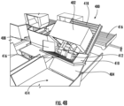
- FIG. 4B illustrates an exemplary perspective view of the container unloader 418 in an inclined position with respect to the front panel 406 attached to the container unloader 418, wherein the container unloader 418 is in the raised orientation, according to one or more embodiments described herein.
- the platform 404 of the container unloader 418 can be configured to move from the first angle to a second angle using an actuator, wherein the second angle is greater than the first angle.
- the platform 404 of the container unloader 418 can be horizontal with respect to the ground surface.
- the actuator can be configured to raise the platform 404 of the container unloader 418 such that the container 402 can be placed at an elevated height with respect to the ground surface.
- the one or more packages such as 412 can move out from the container 402 and lean against a surface of the front panel 406.
- the first side panel 408 and the second side panel 410 of the front panel 406 can be used to ensure that the one or more packages such as 412 do not fall over from one or more edge surfaces of the front panel 406 on the ground surface.
- FIG. 4C illustrates an exemplary perspective view of the container unloader 418 in an inclined position with respect to the front panel 406 attached to the container unloader 418, wherein the front panel 406 is in a lowered orientation, according to one or more embodiments described herein.
- the front panel 406 of the container unloader 418 when the front panel 406 of the container unloader 418 is in the lowered orientation, the one or more packages 412 in the container 402 can be released from the surface of the front panel 406 to a surface of the conveyor 414.
- FIG. 5A illustrates an exemplary perspective view of rotation of a container 502 placed on a container unloader 504 with respect to a front panel 514 and a platform 512 of the container unloader 504 in a warehouse environment 500, wherein the front panel 514 is in a raised orientation, according to one or more embodiments described herein.
- the container 502 can comprise one or more packages.
- the front panel 514 of the container unloader 504 can be moved between the raised orientation and a lowered orientation (shown in FIG. 5B ) using a drive system, wherein the drive system can be at least one or more of a motor drive system, a hydraulic drive system, or any other actuator-based drive system.
- the front panel 514 of the container unloader 504 can further comprise a first side panel 516 and a second side panel 518.
- a front face of the container 502 which faces the front panel 514 can comprise a square opening 510. Further, the front face of the container 502 can comprise a first side panel 506 and a second side panel 508. The square opening 510 can be used to transport the one or more packages in the container 502 to a surface of the front panel 514, wherein the front panel 514 can be in a raised orientation.
- the container 502 can be latched on a roller bed surface on the platform 512 of the container unloader 504 using one or more latches, such that the container 502 is locked in a position on the platform 512 of the container unloader 504.
- the container 502 can rotate in an anti-clockwise direction around a rotational axis X which is normal to the front panel 514 of the container unloader 504.
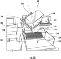
- the container 502 can be configured to be placed on the platform 512 of the container unloader 512 at an offset distance from the front panel 514 of the container unloader 504.
- the offset distance between the container 502 and the front panel 514 of the container unloader 504 can be determined as a minimum distance at which the container 502 can rotate around the rotational axis X which is normal to the front panel 514 of the container unloader 504.
- FIG. 5B illustrates an exemplary perspective view of rotation of the container unloader 504 on which the container 502 is placed, with respect to the front panel 514 connected to the container unloader 504, wherein the front panel 514 is in a lowered orientation, according to one or more embodiments described herein.
- the container 502 can rotate in the anti-clockwise direction around the rotational axis X which is normal to the front panel 514 of the container unloader 504 (as illustrated in the figure). In some other embodiments, the container 502 can rotate in a clockwise direction around the rotational axis X which is normal to the front panel 514 of the container unloader 504.
- FIG. 5C illustrates an exemplary perspective side view of rotation of the container unloader 504 on which the container 502 is placed, with respect to the front panel 514 connected to the container unloader 504, wherein the front panel 514 is in the lowered orientation, according to one or more embodiments described herein.
- a combination of the container unloader 504 and the container 502 which is placed on the container unloader 504 can rotate in the clockwise direction around the rotational axis X, wherein the rotational axis X is normal with respect to the front panel 514 of the container unloader 504.
- FIG. 5D illustrates an exemplary perspective top view of rotation of the container unloader 504 on which the container 502 is placed, with respect to the front panel 514 connected to the container unloader 504, wherein the front panel 514 of the container unloader 504 is in the lowered orientation, according to one or more embodiments described herein.
- the container 502 can be latched in position on the container unloader 504 using one or more latches such as 504 and 526.
- the container unloader 504 can further comprise of the platform 512 on which the container 502 is placed.
- the platform 512 of the container unloader 504 can be moved from a first angle to a second angle using an actuator 532, wherein the second angle is greater than the first angle.
- the actuator 523 has moved the platform 512 from the first angle to the second angle, the container 502 can rotate in the clockwise direction or the anti-clockwise direction around the rotational axis X.
- the container 502 can be placed on a roller bed on the platform 512 of the container unloader 504, such that a combination of the container 502 and the roller bed can rotate with respect to the platform 512 of the container unloader 504.
- the front panel 514 of the container unloader 504 can comprise a first side panel 516 and a second side panel 518.
- the platform 512 of the container unloader 504 can be connected to a conveyor 520, wherein the conveyor 520 can further comprise a pair of side panels, such as 522 and 524.
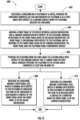
- FIG. 6 illustrates an example flowchart 600 representing a method of releasing a package onto a conveyor using the container unloader, in accordance with some example embodiments described herein.
- a container can be received on a platform of a device, wherein the container can comprise an item. Further, the platform can be placed at a first angle with respect to a ground surface when the platform of the device receives the container.
- a front panel of the device can be moved between a raised orientation and a lowered orientation, such that the front panel of the device can be in the raised orientation when the front panel is orthogonal with respect to the platform of the device, and the front panel of the device can be in the lowered orientation when the front panel and the platform of the device form a continuous surface.
- the platform of the device can be pivoted from the first angle to a second angle with respect to the ground surface, wherein the second angle can be greater than the first angle.
- the container In response to the platform of the device being pivoted from the first angle to a second angle with respect to the ground surface, the container can be rotated around a rotational axis which is normal with respect to the platform of the device such that the item in the container can be configured to lean against a surface of the front panel of the device when the front panel of the container is in the raised orientation, as is disclosed in step 608.
- the container can be rotated around a rotational axis which is normal with respect to the platform of the device such that the item in the container can be configured to lean against a surface of the front panel of the device when the front panel of the container is in the lowered orientation, as is disclosed in step 610.
- exemplary is used herein to mean serving as an example, instance, or illustration. Any aspect or design described herein as “exemplary” is not necessarily to be construed as preferred or advantageous over other aspects or designs. Rather, use of the word exemplary is intended to present concepts in a concrete fashion.
- the term “or” is intended to mean an inclusive “or” rather than an exclusive “or”. That is, unless specified otherwise, or clear from context, "X employs A or B” is intended to mean any of the natural inclusive permutations. That is, if X employs A; X employs B; or X employs both A and B, then "X employs A or B" is satisfied under any of the foregoing instances.
- the articles “a” and “an” as used in this application and the appended claims should generally be construed to mean “one or more” unless specified otherwise or clear from context to be directed to a singular form.
Landscapes
- Engineering & Computer Science (AREA)
- Mechanical Engineering (AREA)
- Loading Or Unloading Of Vehicles (AREA)
- Warehouses Or Storage Devices (AREA)
Claims (13)
- Vorrichtung (100), umfassend:eine Plattform (108), um einen Container (102) aufzunehmen, wobei der Container (102) ein Packstück umfasst und wobei die Plattform (108) in einem ersten Winkel in Bezug zu einer Bodenfläche ist, wenn die Plattform (108) den Container (102) aufnimmt;eine Frontplatte (110), die dazu konfiguriert ist, sich zwischen einer angehobenen Ausrichtung und einer abgesenkten Ausrichtung in Bezug zu der Plattform (108) zu bewegen, wobei als Antwort darauf, dass die Frontplatte (110) in der angehobenen Ausrichtung ist, die Frontplatte (110) orthogonal in Bezug zu der Plattform (108) ist, und als Antwort darauf, dass die Frontplatte (110) in der abgesenkten Ausrichtung ist, die Frontplatte (110) und die Plattform (108) eine kontinuierliche Fläche ausbilden; undeinen Aktuator (112), der mit der Plattform (108) verbunden ist, wobei der Aktuator (112) dazu konfiguriert ist, die Plattform (108) aus dem ersten Winkel in einen zweiten Winkel in Bezug zu der Bodenfläche, der größer ist als der erste Winkel, zu schwenken, wobeigekennzeichnet dadurch, dass die Vorrichtung (100) Folgendes umfasst:sich das Packstück an eine Fläche der Frontplatte (110) anlehnt, wenn die Frontplatte (110) in der angehobenen Ausrichtung ist und die Plattform (108) in dem zweiten Winkel ist; unddas Packstück auf eine Fläche eines Förderbands (118) freigegeben wird, wenn die Frontplatte (110) in der abgesenkten Ausrichtung ist und die Plattform (108) in dem zweiten Winkel ist,
ein Drehgelenk (126), das zwischen der Plattform (108) und dem Container (102) positioniert und dazu konfiguriert ist, den Container (102) in Bezug zu der Frontplatte (110) zu drehen. - Vorrichtung (100) nach Anspruch 1, wobei die Frontplatte (110) ferner eine erste Seitenplatte (106) und eine zweite Seitenplatte (132) umfasst.
- Vorrichtung (100) nach Anspruch 2, wobei die erste Seitenplatte (106) und die zweite Seitenplatte (132) dazu konfiguriert sind, in einer aufrechten Position in Bezug zu einer Fläche der Frontplatte (110) platziert zu sein.
- Vorrichtung (100) nach Anspruch 1, wobei die Vorrichtung ferner ein Walzenbett (104) umfasst, um den Container (102) aufzunehmen, wobei das Walzenbett (104) dazu konfiguriert ist, auf der Plattform (108) positioniert zu sein.
- Vorrichtung (100) nach Anspruch 1, wobei das Drehgelenk (126) den Container (102) um eine Drehachse dreht, die zu der Plattform (108) senkrecht ist.
- Vorrichtung (100) nach Anspruch 1, wobei der Aktuator (112) der Vorrichtung mindestens einer aus einem hydraulischen Aktuator oder einem elektrischen Aktuator ist.
- Vorrichtung (100) nach Anspruch 1, wobei die Frontplatte (110) der Vorrichtung aus einem reibungsmindernden Material zusammengesetzt ist.
- Vorrichtung (100) nach Anspruch 1, wobei die Plattform (108) einen Verriegelungsmechanismus umfasst, um den Container auf einer Fläche der Plattform zu fixieren.
- Vorrichtung (100) nach Anspruch 8, wobei der Verriegelungsmechanismus ferner eine oder mehrere Klinken umfasst.
- Verfahren, umfassend:Aufnehmen (602) eines Containers (102) auf einer Plattform (108) einer Vorrichtung (100) gemäß einem der vorstehenden Ansprüche, wobei der Container (102) ein Objekt umfasst und wobei die Plattform (108) in einem ersten Winkel in Bezug zu einer Bodenfläche ist, wenn die Plattform (108) den Container (102) aufnimmt;Bewegen (604) einer Frontplatte (110) der Vorrichtung (100) zwischen einer angehobenen Ausrichtung und einer abgesenkten Ausrichtung in Bezug zu der Plattform (108), wobei als Antwort darauf, dass die Frontplatte (110) in der angehobenen Ausrichtung ist, die Frontplatte (110) orthogonal in Bezug zu der Plattform (108) ist, und als Antwort darauf, dass die Frontplatte (110) in der abgesenkten Ausrichtung ist, die Frontplatte (110) und die Plattform (108) eine kontinuierliche Fläche ausbilden;Drehen des Containers (102) in Bezug zu der Frontplatte (110) mit einem Drehgelenk (126), das zwischen der Plattform (108) und dem Container (102) positioniert ist; undSchwenken (606) der Plattform (108) aus dem ersten Winkel in einen zweiten Winkel in Bezug zu der Bodenfläche, der größer ist als der erste Winkel, wobei das Schwenken der Plattform (108) in den zweiten Winkel mindestens eines oder mehrere aus Folgendem umfasst:Drehen (608) des Containers um eine Drehachse, die senkrecht in Bezug zu der Plattform ist, um das Objekt in dem Container (102) dazu zu konfigurieren, sich gegen eine Fläche der Frontplatte (110) zu lehnen, wenn die Frontplatte (110) in der angehobenen Ausrichtung ist; undDrehen (610) des Containers (102) um eine Drehachse, die senkrecht in Bezug zu der Plattform (108) ist, um das Objekt dazu zu konfigurieren, auf eine Fläche eines Förderbands (118) freigegeben zu werden, wenn die Frontplatte (110) in der abgesenkten Ausrichtung ist.
- Verfahren nach Anspruch 10, wobei das Verfahren ferner das Konfigurieren einer ersten Seitenplatte (106) und einer zweiten Seitenplatte (132) der Frontplatte (110) der Vorrichtung (100) dazu umfasst, in einer aufrechten Position in Bezug zu einer Fläche der Frontplatte (110) platziert zu sein.
- Verfahren nach Anspruch 10, wobei das Verfahren ferner das Konfigurieren eines Walzenbetts (104) dazu umfasst, den Container (102) aufzunehmen, wobei das Walzenbett (104) auf der Plattform (108) der Vorrichtung (100) positioniert ist.
- Verfahren nach Anspruch 10, wobei das Verfahren ferner das Einklinken des Containers (102) in eine Fläche der Plattform (108) der Vorrichtung (100) unter Verwendung eines Verriegelungsmechanismus umfasst.
Applications Claiming Priority (1)
| Application Number | Priority Date | Filing Date | Title |
|---|---|---|---|
| US17/244,132 US11548742B2 (en) | 2021-04-29 | 2021-04-29 | Automated container unloader |
Publications (2)
| Publication Number | Publication Date |
|---|---|
| EP4086208A1 EP4086208A1 (de) | 2022-11-09 |
| EP4086208B1 true EP4086208B1 (de) | 2024-11-13 |
Family
ID=81307376
Family Applications (1)
| Application Number | Title | Priority Date | Filing Date |
|---|---|---|---|
| EP22167565.5A Active EP4086208B1 (de) | 2021-04-29 | 2022-04-11 | Automatische entladevorrichtung für container |
Country Status (3)
| Country | Link |
|---|---|
| US (3) | US11548742B2 (de) |
| EP (1) | EP4086208B1 (de) |
| CN (1) | CN115258716B (de) |
Families Citing this family (6)
| Publication number | Priority date | Publication date | Assignee | Title |
|---|---|---|---|---|
| WO2021183968A1 (en) * | 2020-03-12 | 2021-09-16 | Leidos Security & Automation Limited | Baggage and parcel handling system and method |
| US11548742B2 (en) * | 2021-04-29 | 2023-01-10 | Intelligrated Headquarters, Llc | Automated container unloader |
| PL4215464T3 (pl) * | 2022-01-25 | 2025-03-10 | Eurosort B.V. | Urządzenie transportowe |
| WO2023205696A1 (en) | 2022-04-20 | 2023-10-26 | Advanced Farm Technologies, Inc. | Item de-binning systems and methods |
| EP4365118A1 (de) | 2022-11-03 | 2024-05-08 | Autostore Technology AS | Warenhalterrotationsstation und verfahren zum extrahieren von waren aus einem warenhalter |
| NL2036217B1 (en) * | 2023-11-08 | 2025-05-19 | Ingb Moderniek B V | An apparatus for unloading a baggage container and a method of unloading a baggage container |
Family Cites Families (16)
| Publication number | Priority date | Publication date | Assignee | Title |
|---|---|---|---|---|
| US3978999A (en) * | 1974-11-08 | 1976-09-07 | Rohr Plessey Corporation | Container discharge damage reduction flap |
| JPS6388624U (de) | 1986-11-28 | 1988-06-09 | ||
| US4802810A (en) * | 1987-09-24 | 1989-02-07 | The Boeing Company | Apparatus for unloading containers |
| JP4591734B2 (ja) | 2000-10-23 | 2010-12-01 | ソニー株式会社 | 荷降し方法および荷降し装置 |
| US6913431B2 (en) * | 2001-04-16 | 2005-07-05 | Southworth Products Corporation | Container unloading apparatus |
| JP2007131308A (ja) * | 2005-11-08 | 2007-05-31 | Hokkaido Seikan Kogyo Kk | 肥料配送用コンテナ装置 |
| JP2014513813A (ja) | 2011-04-15 | 2014-06-05 | テレフオンアクチーボラゲット エル エム エリクソン(パブル) | 適応的な利得−シェイプのレート共用 |
| WO2013008211A1 (en) * | 2011-07-14 | 2013-01-17 | Nortje Gerhard Peter | Container tilting apparatus and method |
| FR3010989B1 (fr) | 2013-09-26 | 2016-05-27 | Materials Tech | Installation de dechargement automatique d'objets d'un conteneur |
| CN206375437U (zh) * | 2017-01-16 | 2017-08-04 | 曹流 | 一种货物自动卸载系统 |
| JP7137186B2 (ja) | 2018-02-05 | 2022-09-14 | 日本協同企画株式会社 | 果菜供給装置 |
| CN209009394U (zh) * | 2018-09-28 | 2019-06-21 | 江西百得标签印刷有限公司 | 一种自动下料生产线 |
| DK3670406T3 (da) * | 2018-12-21 | 2023-05-01 | Siemens Logistics Gmbh | Aflæsning af stykgods fra en lateralt åben stor beholder |
| US11104527B1 (en) * | 2019-02-04 | 2021-08-31 | Amazon Technologies, Inc. | Tote flipper |
| CN113382940B (zh) | 2019-02-27 | 2023-11-07 | 伯克希尔格雷营业股份有限公司 | 用于通过振动来控制物体在容器中的卸放的系统和方法 |
| US11548742B2 (en) * | 2021-04-29 | 2023-01-10 | Intelligrated Headquarters, Llc | Automated container unloader |
-
2021
- 2021-04-29 US US17/244,132 patent/US11548742B2/en active Active
-
2022
- 2022-03-31 CN CN202210333115.7A patent/CN115258716B/zh active Active
- 2022-04-11 EP EP22167565.5A patent/EP4086208B1/de active Active
- 2022-12-08 US US18/063,402 patent/US11993469B2/en active Active
-
2024
- 2024-04-23 US US18/643,841 patent/US12325601B2/en active Active
Also Published As
| Publication number | Publication date |
|---|---|
| CN115258716A (zh) | 2022-11-01 |
| US20230110253A1 (en) | 2023-04-13 |
| EP4086208A1 (de) | 2022-11-09 |
| US12325601B2 (en) | 2025-06-10 |
| US11548742B2 (en) | 2023-01-10 |
| US11993469B2 (en) | 2024-05-28 |
| CN115258716B (zh) | 2025-12-09 |
| US20220348426A1 (en) | 2022-11-03 |
| US20240270516A1 (en) | 2024-08-15 |
Similar Documents
| Publication | Publication Date | Title |
|---|---|---|
| US12325601B2 (en) | Automated container unloader | |
| JP7710998B2 (ja) | 伸縮マストおよびz軸制御を備えた自動荷降ろし・荷積みロボットシステム | |
| US4544319A (en) | Cargo transfer system | |
| US20040247422A1 (en) | Cargo roller system for cargo handling | |
| US6935248B2 (en) | Pallet and conveyor system for loading onto transport | |
| EP3468895B1 (de) | Plattenaufbewahrungsanordnung | |
| WO2005070060A2 (en) | Multiple platform aircraft cargo loader | |
| CN114787039A (zh) | 自主行李设备 | |
| US6702542B1 (en) | Luggage transporter and loader and method therefor | |
| CN110803436B (zh) | 一种水平开合的货物堆叠校正系统 | |
| US11866275B2 (en) | Unloading bulk goods from a laterally open large container | |
| CA2506313C (en) | Mobile pallet with various locking means | |
| JPH06505214A (ja) | ヒンジ式貨物ランプ | |
| EP1930260B1 (de) | Transportfahrzeuge | |
| US5851099A (en) | Adjustable cargo platform assembly | |
| EP1741594B9 (de) | Vorrichtung und Verfahren zur Förderung von Paletten | |
| US12583690B2 (en) | Automated baggage handling carts and systems | |
| EP4240686B1 (de) | Lasthandhabungsvorrichtung und lader | |
| JPH05306016A (ja) | 航空貨物の荷役装置 | |
| CN219488774U (zh) | 一种集装箱自动装卸箱作业机 | |
| US12606390B2 (en) | System and method for bulk transfer-based container unloading | |
| US20050163602A1 (en) | Pallet and conveyor system for loading onto transport | |
| US12447075B2 (en) | Container for transport of a mobility device | |
| JPH06199389A (ja) | 積込み,荷降し用シ−ト及び積込装置 | |
| CA2453472C (en) | Slat carrier |
Legal Events
| Date | Code | Title | Description |
|---|---|---|---|
| PUAI | Public reference made under article 153(3) epc to a published international application that has entered the european phase |
Free format text: ORIGINAL CODE: 0009012 |
|
| STAA | Information on the status of an ep patent application or granted ep patent |
Free format text: STATUS: REQUEST FOR EXAMINATION WAS MADE |
|
| 17P | Request for examination filed |
Effective date: 20220411 |
|
| AK | Designated contracting states |
Kind code of ref document: A1 Designated state(s): AL AT BE BG CH CY CZ DE DK EE ES FI FR GB GR HR HU IE IS IT LI LT LU LV MC MK MT NL NO PL PT RO RS SE SI SK SM TR |
|
| GRAP | Despatch of communication of intention to grant a patent |
Free format text: ORIGINAL CODE: EPIDOSNIGR1 |
|
| STAA | Information on the status of an ep patent application or granted ep patent |
Free format text: STATUS: GRANT OF PATENT IS INTENDED |
|
| INTG | Intention to grant announced |
Effective date: 20240607 |
|
| GRAS | Grant fee paid |
Free format text: ORIGINAL CODE: EPIDOSNIGR3 |
|
| GRAA | (expected) grant |
Free format text: ORIGINAL CODE: 0009210 |
|
| STAA | Information on the status of an ep patent application or granted ep patent |
Free format text: STATUS: THE PATENT HAS BEEN GRANTED |
|
| AK | Designated contracting states |
Kind code of ref document: B1 Designated state(s): AL AT BE BG CH CY CZ DE DK EE ES FI FR GB GR HR HU IE IS IT LI LT LU LV MC MK MT NL NO PL PT RO RS SE SI SK SM TR |
|
| REG | Reference to a national code |
Ref country code: GB Ref legal event code: FG4D |
|
| REG | Reference to a national code |
Ref country code: CH Ref legal event code: EP |
|
| REG | Reference to a national code |
Ref country code: DE Ref legal event code: R096 Ref document number: 602022007613 Country of ref document: DE |
|
| REG | Reference to a national code |
Ref country code: IE Ref legal event code: FG4D |
|
| REG | Reference to a national code |
Ref country code: LT Ref legal event code: MG9D |
|
| REG | Reference to a national code |
Ref country code: NL Ref legal event code: MP Effective date: 20241113 |
|
| PG25 | Lapsed in a contracting state [announced via postgrant information from national office to epo] |
Ref country code: HR Free format text: LAPSE BECAUSE OF FAILURE TO SUBMIT A TRANSLATION OF THE DESCRIPTION OR TO PAY THE FEE WITHIN THE PRESCRIBED TIME-LIMIT Effective date: 20241113 Ref country code: PT Free format text: LAPSE BECAUSE OF FAILURE TO SUBMIT A TRANSLATION OF THE DESCRIPTION OR TO PAY THE FEE WITHIN THE PRESCRIBED TIME-LIMIT Effective date: 20250313 Ref country code: IS Free format text: LAPSE BECAUSE OF FAILURE TO SUBMIT A TRANSLATION OF THE DESCRIPTION OR TO PAY THE FEE WITHIN THE PRESCRIBED TIME-LIMIT Effective date: 20250313 |
|
| PG25 | Lapsed in a contracting state [announced via postgrant information from national office to epo] |
Ref country code: FI Free format text: LAPSE BECAUSE OF FAILURE TO SUBMIT A TRANSLATION OF THE DESCRIPTION OR TO PAY THE FEE WITHIN THE PRESCRIBED TIME-LIMIT Effective date: 20241113 Ref country code: NL Free format text: LAPSE BECAUSE OF FAILURE TO SUBMIT A TRANSLATION OF THE DESCRIPTION OR TO PAY THE FEE WITHIN THE PRESCRIBED TIME-LIMIT Effective date: 20241113 |
|
| REG | Reference to a national code |
Ref country code: AT Ref legal event code: MK05 Ref document number: 1741552 Country of ref document: AT Kind code of ref document: T Effective date: 20241113 |
|
| PG25 | Lapsed in a contracting state [announced via postgrant information from national office to epo] |
Ref country code: BG Free format text: LAPSE BECAUSE OF FAILURE TO SUBMIT A TRANSLATION OF THE DESCRIPTION OR TO PAY THE FEE WITHIN THE PRESCRIBED TIME-LIMIT Effective date: 20241113 |
|
| PG25 | Lapsed in a contracting state [announced via postgrant information from national office to epo] |
Ref country code: ES Free format text: LAPSE BECAUSE OF FAILURE TO SUBMIT A TRANSLATION OF THE DESCRIPTION OR TO PAY THE FEE WITHIN THE PRESCRIBED TIME-LIMIT Effective date: 20241113 |
|
| PG25 | Lapsed in a contracting state [announced via postgrant information from national office to epo] |
Ref country code: NO Free format text: LAPSE BECAUSE OF FAILURE TO SUBMIT A TRANSLATION OF THE DESCRIPTION OR TO PAY THE FEE WITHIN THE PRESCRIBED TIME-LIMIT Effective date: 20250213 |
|
| PG25 | Lapsed in a contracting state [announced via postgrant information from national office to epo] |
Ref country code: GR Free format text: LAPSE BECAUSE OF FAILURE TO SUBMIT A TRANSLATION OF THE DESCRIPTION OR TO PAY THE FEE WITHIN THE PRESCRIBED TIME-LIMIT Effective date: 20250214 Ref country code: AT Free format text: LAPSE BECAUSE OF FAILURE TO SUBMIT A TRANSLATION OF THE DESCRIPTION OR TO PAY THE FEE WITHIN THE PRESCRIBED TIME-LIMIT Effective date: 20241113 Ref country code: LV Free format text: LAPSE BECAUSE OF FAILURE TO SUBMIT A TRANSLATION OF THE DESCRIPTION OR TO PAY THE FEE WITHIN THE PRESCRIBED TIME-LIMIT Effective date: 20241113 |
|
| PG25 | Lapsed in a contracting state [announced via postgrant information from national office to epo] |
Ref country code: PL Free format text: LAPSE BECAUSE OF FAILURE TO SUBMIT A TRANSLATION OF THE DESCRIPTION OR TO PAY THE FEE WITHIN THE PRESCRIBED TIME-LIMIT Effective date: 20241113 |
|
| PG25 | Lapsed in a contracting state [announced via postgrant information from national office to epo] |
Ref country code: RS Free format text: LAPSE BECAUSE OF FAILURE TO SUBMIT A TRANSLATION OF THE DESCRIPTION OR TO PAY THE FEE WITHIN THE PRESCRIBED TIME-LIMIT Effective date: 20250213 |
|
| PG25 | Lapsed in a contracting state [announced via postgrant information from national office to epo] |
Ref country code: SM Free format text: LAPSE BECAUSE OF FAILURE TO SUBMIT A TRANSLATION OF THE DESCRIPTION OR TO PAY THE FEE WITHIN THE PRESCRIBED TIME-LIMIT Effective date: 20241113 |
|
| PGFP | Annual fee paid to national office [announced via postgrant information from national office to epo] |
Ref country code: DE Payment date: 20250428 Year of fee payment: 4 |
|
| PG25 | Lapsed in a contracting state [announced via postgrant information from national office to epo] |
Ref country code: DK Free format text: LAPSE BECAUSE OF FAILURE TO SUBMIT A TRANSLATION OF THE DESCRIPTION OR TO PAY THE FEE WITHIN THE PRESCRIBED TIME-LIMIT Effective date: 20241113 |
|
| PG25 | Lapsed in a contracting state [announced via postgrant information from national office to epo] |
Ref country code: EE Free format text: LAPSE BECAUSE OF FAILURE TO SUBMIT A TRANSLATION OF THE DESCRIPTION OR TO PAY THE FEE WITHIN THE PRESCRIBED TIME-LIMIT Effective date: 20241113 |
|
| PGFP | Annual fee paid to national office [announced via postgrant information from national office to epo] |
Ref country code: FR Payment date: 20250424 Year of fee payment: 4 |
|
| PG25 | Lapsed in a contracting state [announced via postgrant information from national office to epo] |
Ref country code: RO Free format text: LAPSE BECAUSE OF FAILURE TO SUBMIT A TRANSLATION OF THE DESCRIPTION OR TO PAY THE FEE WITHIN THE PRESCRIBED TIME-LIMIT Effective date: 20241113 |
|
| PG25 | Lapsed in a contracting state [announced via postgrant information from national office to epo] |
Ref country code: SK Free format text: LAPSE BECAUSE OF FAILURE TO SUBMIT A TRANSLATION OF THE DESCRIPTION OR TO PAY THE FEE WITHIN THE PRESCRIBED TIME-LIMIT Effective date: 20241113 |
|
| PG25 | Lapsed in a contracting state [announced via postgrant information from national office to epo] |
Ref country code: CZ Free format text: LAPSE BECAUSE OF FAILURE TO SUBMIT A TRANSLATION OF THE DESCRIPTION OR TO PAY THE FEE WITHIN THE PRESCRIBED TIME-LIMIT Effective date: 20241113 |
|
| PG25 | Lapsed in a contracting state [announced via postgrant information from national office to epo] |
Ref country code: IT Free format text: LAPSE BECAUSE OF FAILURE TO SUBMIT A TRANSLATION OF THE DESCRIPTION OR TO PAY THE FEE WITHIN THE PRESCRIBED TIME-LIMIT Effective date: 20241113 |
|
| REG | Reference to a national code |
Ref country code: DE Ref legal event code: R097 Ref document number: 602022007613 Country of ref document: DE |
|
| PG25 | Lapsed in a contracting state [announced via postgrant information from national office to epo] |
Ref country code: SE Free format text: LAPSE BECAUSE OF FAILURE TO SUBMIT A TRANSLATION OF THE DESCRIPTION OR TO PAY THE FEE WITHIN THE PRESCRIBED TIME-LIMIT Effective date: 20241113 |
|
| PLBE | No opposition filed within time limit |
Free format text: ORIGINAL CODE: 0009261 |
|
| STAA | Information on the status of an ep patent application or granted ep patent |
Free format text: STATUS: NO OPPOSITION FILED WITHIN TIME LIMIT |
|
| 26N | No opposition filed |
Effective date: 20250814 |
|
| REG | Reference to a national code |
Ref country code: CH Ref legal event code: H13 Free format text: ST27 STATUS EVENT CODE: U-0-0-H10-H13 (AS PROVIDED BY THE NATIONAL OFFICE) Effective date: 20251125 |
|
| PG25 | Lapsed in a contracting state [announced via postgrant information from national office to epo] |
Ref country code: LU Free format text: LAPSE BECAUSE OF NON-PAYMENT OF DUE FEES Effective date: 20250411 |
|
| PG25 | Lapsed in a contracting state [announced via postgrant information from national office to epo] |
Ref country code: MC Free format text: LAPSE BECAUSE OF FAILURE TO SUBMIT A TRANSLATION OF THE DESCRIPTION OR TO PAY THE FEE WITHIN THE PRESCRIBED TIME-LIMIT Effective date: 20241113 |
|
| REG | Reference to a national code |
Ref country code: BE Ref legal event code: MM Effective date: 20250430 |
|
| PG25 | Lapsed in a contracting state [announced via postgrant information from national office to epo] |
Ref country code: BE Free format text: LAPSE BECAUSE OF NON-PAYMENT OF DUE FEES Effective date: 20250430 |
|
| PG25 | Lapsed in a contracting state [announced via postgrant information from national office to epo] |
Ref country code: CH Free format text: LAPSE BECAUSE OF NON-PAYMENT OF DUE FEES Effective date: 20250430 |
|
| PG25 | Lapsed in a contracting state [announced via postgrant information from national office to epo] |
Ref country code: IE Free format text: LAPSE BECAUSE OF NON-PAYMENT OF DUE FEES Effective date: 20250411 |