EP4086153B1 - Fahrradumwerfer - Google Patents
Fahrradumwerfer Download PDFInfo
- Publication number
- EP4086153B1 EP4086153B1 EP22172003.0A EP22172003A EP4086153B1 EP 4086153 B1 EP4086153 B1 EP 4086153B1 EP 22172003 A EP22172003 A EP 22172003A EP 4086153 B1 EP4086153 B1 EP 4086153B1
- Authority
- EP
- European Patent Office
- Prior art keywords
- generator
- coupled
- pulley
- gear
- cage
- Prior art date
- Legal status (The legal status is an assumption and is not a legal conclusion. Google has not performed a legal analysis and makes no representation as to the accuracy of the status listed.)
- Active
Links
Images












Classifications
-
- B—PERFORMING OPERATIONS; TRANSPORTING
- B62—LAND VEHICLES FOR TRAVELLING OTHERWISE THAN ON RAILS
- B62M—RIDER PROPULSION OF WHEELED VEHICLES OR SLEDGES; POWERED PROPULSION OF SLEDGES OR SINGLE-TRACK CYCLES; TRANSMISSIONS SPECIALLY ADAPTED FOR SUCH VEHICLES
- B62M9/00—Transmissions characterised by use of an endless chain, belt, or the like
- B62M9/04—Transmissions characterised by use of an endless chain, belt, or the like of changeable ratio
- B62M9/06—Transmissions characterised by use of an endless chain, belt, or the like of changeable ratio using a single chain, belt, or the like
- B62M9/10—Transmissions characterised by use of an endless chain, belt, or the like of changeable ratio using a single chain, belt, or the like involving different-sized wheels, e.g. rear sprocket chain wheels selectively engaged by the chain, belt, or the like
- B62M9/12—Transmissions characterised by use of an endless chain, belt, or the like of changeable ratio using a single chain, belt, or the like involving different-sized wheels, e.g. rear sprocket chain wheels selectively engaged by the chain, belt, or the like the chain, belt, or the like being laterally shiftable, e.g. using a rear derailleur
- B62M9/121—Rear derailleurs
-
- B—PERFORMING OPERATIONS; TRANSPORTING
- B62—LAND VEHICLES FOR TRAVELLING OTHERWISE THAN ON RAILS
- B62M—RIDER PROPULSION OF WHEELED VEHICLES OR SLEDGES; POWERED PROPULSION OF SLEDGES OR SINGLE-TRACK CYCLES; TRANSMISSIONS SPECIALLY ADAPTED FOR SUCH VEHICLES
- B62M9/00—Transmissions characterised by use of an endless chain, belt, or the like
- B62M9/04—Transmissions characterised by use of an endless chain, belt, or the like of changeable ratio
- B62M9/06—Transmissions characterised by use of an endless chain, belt, or the like of changeable ratio using a single chain, belt, or the like
- B62M9/10—Transmissions characterised by use of an endless chain, belt, or the like of changeable ratio using a single chain, belt, or the like involving different-sized wheels, e.g. rear sprocket chain wheels selectively engaged by the chain, belt, or the like
- B62M9/12—Transmissions characterised by use of an endless chain, belt, or the like of changeable ratio using a single chain, belt, or the like involving different-sized wheels, e.g. rear sprocket chain wheels selectively engaged by the chain, belt, or the like the chain, belt, or the like being laterally shiftable, e.g. using a rear derailleur
- B62M9/121—Rear derailleurs
- B62M9/124—Mechanisms for shifting laterally
-
- B—PERFORMING OPERATIONS; TRANSPORTING
- B62—LAND VEHICLES FOR TRAVELLING OTHERWISE THAN ON RAILS
- B62M—RIDER PROPULSION OF WHEELED VEHICLES OR SLEDGES; POWERED PROPULSION OF SLEDGES OR SINGLE-TRACK CYCLES; TRANSMISSIONS SPECIALLY ADAPTED FOR SUCH VEHICLES
- B62M9/00—Transmissions characterised by use of an endless chain, belt, or the like
- B62M9/04—Transmissions characterised by use of an endless chain, belt, or the like of changeable ratio
- B62M9/06—Transmissions characterised by use of an endless chain, belt, or the like of changeable ratio using a single chain, belt, or the like
- B62M9/10—Transmissions characterised by use of an endless chain, belt, or the like of changeable ratio using a single chain, belt, or the like involving different-sized wheels, e.g. rear sprocket chain wheels selectively engaged by the chain, belt, or the like
- B62M9/12—Transmissions characterised by use of an endless chain, belt, or the like of changeable ratio using a single chain, belt, or the like involving different-sized wheels, e.g. rear sprocket chain wheels selectively engaged by the chain, belt, or the like the chain, belt, or the like being laterally shiftable, e.g. using a rear derailleur
- B62M9/121—Rear derailleurs
- B62M9/124—Mechanisms for shifting laterally
- B62M9/1242—Mechanisms for shifting laterally characterised by the linkage mechanisms
-
- B—PERFORMING OPERATIONS; TRANSPORTING
- B62—LAND VEHICLES FOR TRAVELLING OTHERWISE THAN ON RAILS
- B62M—RIDER PROPULSION OF WHEELED VEHICLES OR SLEDGES; POWERED PROPULSION OF SLEDGES OR SINGLE-TRACK CYCLES; TRANSMISSIONS SPECIALLY ADAPTED FOR SUCH VEHICLES
- B62M9/00—Transmissions characterised by use of an endless chain, belt, or the like
- B62M9/04—Transmissions characterised by use of an endless chain, belt, or the like of changeable ratio
- B62M9/06—Transmissions characterised by use of an endless chain, belt, or the like of changeable ratio using a single chain, belt, or the like
- B62M9/10—Transmissions characterised by use of an endless chain, belt, or the like of changeable ratio using a single chain, belt, or the like involving different-sized wheels, e.g. rear sprocket chain wheels selectively engaged by the chain, belt, or the like
- B62M9/12—Transmissions characterised by use of an endless chain, belt, or the like of changeable ratio using a single chain, belt, or the like involving different-sized wheels, e.g. rear sprocket chain wheels selectively engaged by the chain, belt, or the like the chain, belt, or the like being laterally shiftable, e.g. using a rear derailleur
- B62M9/121—Rear derailleurs
- B62M9/124—Mechanisms for shifting laterally
- B62M2009/12406—Rear derailleur comprising a rigid pivoting arm
-
- B—PERFORMING OPERATIONS; TRANSPORTING
- B62—LAND VEHICLES FOR TRAVELLING OTHERWISE THAN ON RAILS
- B62M—RIDER PROPULSION OF WHEELED VEHICLES OR SLEDGES; POWERED PROPULSION OF SLEDGES OR SINGLE-TRACK CYCLES; TRANSMISSIONS SPECIALLY ADAPTED FOR SUCH VEHICLES
- B62M9/00—Transmissions characterised by use of an endless chain, belt, or the like
- B62M9/04—Transmissions characterised by use of an endless chain, belt, or the like of changeable ratio
- B62M9/06—Transmissions characterised by use of an endless chain, belt, or the like of changeable ratio using a single chain, belt, or the like
- B62M9/10—Transmissions characterised by use of an endless chain, belt, or the like of changeable ratio using a single chain, belt, or the like involving different-sized wheels, e.g. rear sprocket chain wheels selectively engaged by the chain, belt, or the like
- B62M9/12—Transmissions characterised by use of an endless chain, belt, or the like of changeable ratio using a single chain, belt, or the like involving different-sized wheels, e.g. rear sprocket chain wheels selectively engaged by the chain, belt, or the like the chain, belt, or the like being laterally shiftable, e.g. using a rear derailleur
- B62M9/121—Rear derailleurs
- B62M9/122—Rear derailleurs electrically or fluid actuated; Controls thereof
-
- B—PERFORMING OPERATIONS; TRANSPORTING
- B62—LAND VEHICLES FOR TRAVELLING OTHERWISE THAN ON RAILS
- B62M—RIDER PROPULSION OF WHEELED VEHICLES OR SLEDGES; POWERED PROPULSION OF SLEDGES OR SINGLE-TRACK CYCLES; TRANSMISSIONS SPECIALLY ADAPTED FOR SUCH VEHICLES
- B62M9/00—Transmissions characterised by use of an endless chain, belt, or the like
- B62M9/04—Transmissions characterised by use of an endless chain, belt, or the like of changeable ratio
- B62M9/06—Transmissions characterised by use of an endless chain, belt, or the like of changeable ratio using a single chain, belt, or the like
- B62M9/10—Transmissions characterised by use of an endless chain, belt, or the like of changeable ratio using a single chain, belt, or the like involving different-sized wheels, e.g. rear sprocket chain wheels selectively engaged by the chain, belt, or the like
- B62M9/12—Transmissions characterised by use of an endless chain, belt, or the like of changeable ratio using a single chain, belt, or the like involving different-sized wheels, e.g. rear sprocket chain wheels selectively engaged by the chain, belt, or the like the chain, belt, or the like being laterally shiftable, e.g. using a rear derailleur
- B62M9/121—Rear derailleurs
- B62M9/126—Chain guides; Mounting thereof
Definitions
- the present application generally relates to a bicycle derailleur, including for example and without limitation a bicycle rear derailleur incorporating an energy harvesting system.
- Bicycle derailleurs are commonly incorporated into a drivetrain of a bicycle.
- the typical drivetrain also includes a crank assembly that is coupled to one or more drive sprockets.
- the crank assembly is operable to drive a chain that is routed or wrapped around one of the drive sprockets.
- the chain may also be routed to one of wheels of the bicycle, for example a rear wheel, wherein the chain may engage one or more driven sprockets.
- Derailleur e.g., front
- another derailleur e.g., rear
- the driven sprockets for example adjacent the rear wheel.
- the derailleur(s) may be actuated to selectively shift the chain of the drivetrain between the drive sprockets, and/or to selectively shift the chain between the one or more of the driven sprockets. Shifting of the bicycle chain from one drive sprocket to another, or from one driven sprocket to another, is done in order to change the gear ratio of the drivetrain.
- the rear derailleur may also apply a tension to the chain to take-up slack, as well as to maintain the desired tension, in the chain on the non-drive-side of the drivetrain.
- the rear derailleur may be a wireless, electrically actuated rear derailleur, which relies on a battery to supply power to a motor.
- the battery may need to be periodically charged or replaced, which may be an inconvenience if the battery is discharged during use of the bicycle, or at a remote location not conveniently located to a charging station or providing access to replacement batteries.
- the invention relates to a bicycle derailleur according to claim 1.
- the dependent claims relate to further embodiments of the invention.
- a bicycle derailleur includes a base member mountable to a bicycle frame and a cage assembly moveably coupled to the base member.
- the cage assembly is moveable in opposite first and second directions relative to the base member.
- a motor is coupled to and moveable with the cage assembly in the opposite first and second directions.
- the motor is operable to move the cage assembly in the opposite first and second directions, wherein the motor is mounted on the cage assembly.
- the cage assembly may include a chain pulley rotatably coupled to the cage assembly about a first rotation axis.
- one embodiment of a bicycle derailleur may include a base member mountable to a bicycle frame and a cage assembly moveably coupled to the base member.
- An electrical generator system may be coupled to and moveable with the cage assembly.
- the electrical generator system may include a generator and a generator drive system.
- the generator drive system may include a chain pulley rotatably coupled to the cage assembly about a first rotation axis and a generator transmission operably coupled between the chain pulley and the generator.
- one embodiment of a bicycle derailleur may include a base member mountable to a bicycle frame and a cage assembly moveably coupled to the base member.
- An electrical generator system may be coupled to and moveable with the cage assembly.
- the electrical generator system may include a generator and a generator drive system.
- the generator drive system may include a chain pulley rotatable about a first rotation axis in opposite first and second rotational directions and a clutch.
- the clutch may driveably connect the chain pulley and the generator when the chain pulley is rotated in the first rotational direction such that the generator is activated.
- the clutch disconnects the chain pulley and the generator when the chain pulley is rotated in the second rotational direction such that the generator is deactivated.
- a bicycle derailleur may include a base member mountable to a bicycle frame and a cage assembly moveably coupled to the base member.
- An electrical generator system may be coupled to and moveable with the cage assembly.
- the electrical generator system may include a generator and a generator drive system.
- the generator drive system may include a chain pulley rotatable about a first rotation axis, at least first and second pulleys rotatable about second and third rotation axes respectively, and a belt engaged with the first and second pulleys.
- the first and second pulleys may have a pulley ratio greater than 1.
- the various aspects and embodiments of the derailleur, and the methods for the use and assembly thereof, may provide significant advantages over other derailleur and methods.
- the motor and/or the electrical generator system may be mounted on and moveable with the cage. If damaged, the cage, including the motor and electrical generator system, may be quickly and easily replaced without having to replace the other components of the derailleur.
- the cage which may include a chain pulley engageable by a chain, provides an input to the generator system and motor, with the components being positionally fixed relative to each other and moveable with the cage as the cage is: (1) moved laterally during a gear changing sequence, and/or (2) rotated to maintain a tension in the chain.
- the assembly avoids the need for couplings, whether electrical or mechanical, between any components located on the cage and components located on other parts of the derailleur, which may be moveable relative to each other.
- the electrical generator system ensures that power is always available to power the motor, for example during shifting, and/or for other activities and accessories requiring electrical power.
- the term “plurality,” as used herein, means two or more.
- the term “longitudinal,” as used herein means of or relating to a length or lengthwise direction.
- the term “lateral,” as used herein, means situated on, directed toward or running in a side-to-side direction.
- the term “coupled” means connected to or engaged with, whether directly or indirectly, for example with an intervening member, and does not require the engagement to be fixed or permanent, although it may be fixed or permanent.
- first,” “second,” and so on, as used herein are not meant to be assigned to a particular component so designated, but rather are simply referring to such components in the numerical order as addressed, meaning that a component designated as “first” may later be a “second” such component, depending on the order in which it is referred. It should also be understood that designation of “first” and “second” does not necessarily mean that the two components or values so designated are different, meaning for example a first direction may be the same as a second direction, with each simply being applicable to different components.
- upper,” “lower,” “rear,” “front,” “fore,” “aft,” “vertical,” “horizontal,” “right,” “left,” “inboard,” “outboard” and variations or derivatives thereof, refer to the orientations of an exemplary bicycle 150, shown in FIG. 37 , from the perspective of a user seated thereon, for example with an “inboard” component or feature being closer to a vertical mid-plane of the bicycle extending in a direction 201.
- transverse means non-parallel.
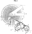
- outer and outwardly refers to a direction or feature facing away from a centralized location, for example the phrases “radially outwardly,” “radial direction” and/or derivatives thereof, refer to a feature diverging away from a centralized location, for example a rotation axis 152 of the cassette 3 as shown in FIG. 2 .
- inner and inwardly refers to a direction facing toward the centralized or interior location.
- subassembly refers to an assembly of a plurality of components, with subassemblies capable of being further assembled into other subassemblies and/or a final assembly, such as the bicycle 150.
- FIG. 37 illustrates one example of a human powered vehicle.
- the vehicle is one possible type of bicycle 150, such as a road bicycle.
- the bicycle 150 has a frame 2, handlebars 154 near a front end of the frame, and a seat or saddle 156 for supporting a rider over a top of the frame.
- the bicycle 150 has a first or front wheel 158 carried by a front fork subassembly 160 supporting the front end of the frame.
- the bicycle 150 also has a second or rear wheel 162 supporting a rear end of the frame 2, which includes a pair of chain stays 164 connected to a pair of seat stays 165 (see also FIG. 1 ).
- the rear end of the frame 2 may be supported by a rear suspension component, such as a rear shock 167.
- FIG. 37 a normal riding or forward moving direction 201 of the bicycle 150 is shown. While the bicycle 150 depicted in FIG. 37 is a mountain bicycle, the rear gear change device, or rear derailleur 180, including the specific embodiments and examples disclosed herein as well as alternative embodiments and examples, may be implemented on other types of bicycles. For example and without limitation, the disclosed rear derailleur 180 may be used on road bicycles, and any other type of bicycle incorporating a derailleur. It should be understood that the various energy harvesting systems and embodiments disclosed herein may also be incorporated into derailleurs, at any location (e.g., front), having a cage assembly with a rotatable wheel.
- the base member 5, moveable member 8, inner link 7, and outer link 6 form a four-bar linkage, and in particular a parallelogram linkage 186.
- the moveable member 8 may be moveably coupled to the base member 5.
- the moveable member 8 is moveable relative to the base member 5, and the frame 2, in opposite inboard and outboard directions. It should be understood that the moveable member 8 may be moveably connected to the base member 5 with other components and/or linkages other than the disclosed linkage, which may or may not include one or more links.
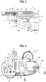
- the cage assembly 9 may include one or both of an outer cage 24 secured to an inner cage 25, for example with fasteners 29, 30, configured as screws, a snap-fit, and/or other know suitable securing devices.
- the lower chain pulley 22 rotates on a ball bearing having an inner race clamped between the inner cage 25 and the outer cage 24 with the fasteners, configured as a screw 30, threaded into the inner cage 25. This connection also serves to fix the inner cage 25 to the outer cage 24.
- a cover 23 is fixed to the outer cage 24 with a plurality of fasteners 28, shown as nine screws, spaced apart around the perimeter of the cover 23, with the cover and outer cage defining a housing 200.
- housing refers to a component capable of supporting or holding other components, and may be enclosed or open.
- the outer cage and/or cover may each individually define a housing, or may in combination define the housing 200, which is enclosed and sealed to prevent the intrusion of fluid into an interior of the housing in one embodiment.
- an elastomeric sealing element 32 may be disposed in a groove 202 formed in the outer cage 24. It should be understood that the groove may alternatively be formed in the cover.
- the groove 202 may define a closed loop that follows the contour of the perimeter of the cover 23, with the sealing element 32 forming a fluid-tight seal between the outer cage 24 and cover 23, or housing 200.
- the fastener 29 is threadably engaged with outer cage 24, and fixes the inner cage 25 to the outer cage 24.
- one embodiment of the upper wheel pulley assembly include a sealed ball bearing assembly 33 received in a recess 204 formed in the outer cage 24 and engaged by the shoulder of an annular flange 206.
- a ball bearing assembly 34 is received in a recess 208 formed in the cover 23, and is supported on an outer side surface 210 of the housing.
- a pulley shaft 35 is disposed inside, and supported by, the inner races of ball bearing assemblies 33 and 34.
- the pulley shaft 35 has an end 212 rotatably supported by the ball bearing assembly 34, with an annular shoulder 214 engaging the inner race and trapping the bearing assembly 34 between the shoulder 214 and the surface 210.
- the pulley shaft 35 includes an annular flange 216 spaced laterally from the annular shoulder 214, with the annular flange 216 defining a second annular shoulder 218 engaging the inner race of the ball bearing 34 and trapping the bearing assembly 33 between the shoulder 218 and the annular flange 206.
- the annular shoulders 214, 216 face in opposite directions such that the annular shoulders limit the axial movement of the shaft 35 in both lateral directions (inboard and outboard).
- the ball bearing assembly 33 is captured between the outer cage 24, or an annular shoulder defined thereby, and the annular shoulder 216 of the shaft 35.
- a sealing element 346 configured in one embodiment as an O-ring, is located in a circumferential groove 220 formed in the shaft 35 inboard and spaced apart from the annular flange 216.
- the groove may alternatively be formed in the ball bearing assembly.
- the sealing element 346 forms a fluid-tight seal between the pulley shaft 35 and the inner race of the ball bearing assembly 33, such that fluid is prevented from entering the interior space of the housing 200 defined between the cover 23 and the outer cage 24.
- the pulley shaft 35 may include an axially extending hole 222.
- the hole 222 may be threaded and threadably engaged by a fastener 31, shown as a screw.
- the upper chain pulley 21 may include a key hole 21b, having a cross-shaped recess 226 in one embodiment.
- the pulley shaft 35 may be configured with a corresponding key 224, or insert portion configured with mating corresponding cross-shaped protrusions 35b.
- the key 224 interfaces and ensures a non-rotatable engagement or coupling with the key hole 21b, for example by way of the engagement of the recesses 226 by the protrusions 35b.
- the chain pulley 21 includes a hub 228 having an inner surface 230 that abuts an end surface 35a of the pulley shaft 35 defined between the protrusions 35b.
- the upper chain pulley 21 is non-rotatably and axially secured to the pulley shaft 35, such that torsion may be transmitted between the upper chain pulley 21 and the pulley shaft 35 via the key 224 and key hole 21b, i.e., between the protrusions 35b and recesses 226.
- the pulley shaft 35 is captured between the cover 23 and the outer cage 24, with the chain pulley 21 secured to the shaft 35. As such, the chain pulley 21 is not captured or clamped between the inner and outer cages 25, 24.
- the chain pulley 21 is supported in a cantilevered fashion on an end of the shaft 35, which is supported by the housing 200 outboard of the chain pulley 21.
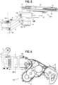
- the inner cage 25 may not overlie the chain pulley 21, and in particular the pulley shaft 35, but rather may be configured to provide clearance between the inner cage 25 and the upper pulley system as shown in FIG. 9 .
- the inner cage 25 therefore, does not need to be removed from the outer cage 24.
- the inner cage may overlie the chain pulley.
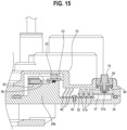
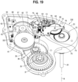
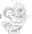
- an electrical generator system 240 is coupled to and moveable with the cage assembly 9, meaning the electrical generator system 240 translates and rotates with the cage assembly 9 as the cage assembly moves relative to the moving member 8, base 5 and bicycle frame 2. Put another way, the electrical generator system is fixed to the cage assembly and follows the movement path of the cage assembly.
- the electrical generator system 240 is disposed in the housing 200, defined by the cover 23 and outer cage 24, and may be entirely enclosed within a sealed interior cavity 242 defined between the cover 23 and outer cage 24.
- the electrical generator system 240 includes a generator 50 and a generator drive system 244, with the generator drive system 244 including an input.
- the input may be configured in one embodiment as the chain pulley 21 rotatably coupled to the housing 200, and the outer cage 24 and cover 23 in particular.
- the chain pulley 21 is rotatable about a rotation axis 246.
- the generator drive system may further include a generator transmission 250 operably coupled between the input, e.g., chain pulley 21, an output, e.g., the generator 50.
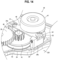
- the generator transmission 250 includes a first generator spur gear 37, which is non-rotatably and axially fixed to the pulley shaft 35, such that the spur gear 37 rotates with the chain pulley 21 about the rotation axis 246.
- the spur gear 37 may be fixed to the pulley shaft with a friction fit, and/or with a spline interface.
- the spur gear 37 is disposed in a space, or interior cavity 242, defined between the cover and outer cage.
- the first generator spur gear 37 has a plurality of teeth 260 spaced circumferentially around the perimeter of the spur gear, with the teeth 260 engaged with teeth 262 spaced circumferentially around the perimeter of a pinion gear 38.
- the pinion gear 38 is rotatable about an axle 44 supported by and between the outer cage 24 and cover 23.
- the spur gear 37 has thirty (30) teeth 260, while the pinion gear 38 has ten (10) teeth 262, providing a gear ratio of 3:1, meaning that one rotation of the spur gear 37 results in three (3) rotations of the pinion gear 38.
- the chain pulley 21 has a plurality of teeth, for example 12.
- the axle 44 has a first end engaged with the outer cage 24, for example a non-rotatable engagement, e.g., threaded, such that the axle 44 is non-rotatable, with an opposite second end engaged with the cover 23. Alternatively, the axle 44 may be allowed to rotate relative to the outer cage 24.
- the pinion gear 38 includes a hub 264 that rotates on the axle 44 about a rotation axis 266.
- a second generator spur gear 39 is co-axially and non-rotatably fixed to first generator pinion gear 38, 338, and to the hub 264 in particular, and rotates with and is driven by the pinion gear 38, 338.
- the spur gear 39, 339 has thirty-six (36) teeth 268 spaced circumferentially around a perimeter thereof in one embodiment.
- the teeth 268 of the spur gear engage teeth 270 spaced circumferentially around the perimeter of a pinion gear 40, which is supported by and rotatable about an axle 45 rotatably or non-rotatably supported by and between the outer cage 24 and cover 23.
- the axle 45 has a first end engaged with the outer cage 24, for example a threadable engagement such that the axle is non-rotatable, with an opposite second end engaged with the housing 24.
- the axle is rotatably supported by and between the outer cage 24 and cover 23.
- the pinion gear 40 includes a hub 274 that rotates on the axle about a rotation axis 272.
- the pinion gear may have for example twelve (12) teeth 270, providing a gear ratio of 3:1 between the spur gear 39 and pinion gear 40, meaning that one rotation of the spur gear 39 results in three (3) rotations of the pinion gear 40.
- the generator transmission 250 also includes at least first and second pulleys 41, 42 rotatably coupled to the housing 200 about rotation axes 272, 280 respectively, and a belt 43 engaged with the first and second pulleys.
- a first generator pulley 41 preferably has a plurality of teeth 276, for example 75 teeth 276, and is co-axially and non-rotatably fixed to the hub 274 of the pinion gear 40, with the pulley 41 and pinion gear 40 being rotatable about the rotation axis 272.
- the second pulley 42 has a plurality of teeth 278, for example 20 teeth, and is co-axially and non-rotatably fixed to a rotor 47 of the generator 50, with the pulley 42 and rotor 47 being rotatable about the rotation axis 280.
- a belt 43 forms a continuous or endless loop.
- the belt 43 may be a toothed belt having a plurality of teeth 282 formed around an inner surface of the loop.
- the belt 43 may include for example and without limitation 91 teeth 282.
- the belt 43, and the teeth 282 in particular, are engaged with the first and second pulleys 41, 42 and the teeth 276, 278 thereof.
- the pulleys 41, 42 have a pulley ratio of greater than 1, and in one embodiment a ratio of 3.75:1. It should be understood that in other embodiments, the belt 43 and pulleys 41, 42 may be configured without teeth, with the belt 43 engaging the pulleys 41, 42 by way of friction.
- the rotor 47 is rotatably received in a bore 284 defined by a generator base 46.
- the generator 50 includes a stator 48 disposed inside an outer periphery, or annular wall 286, of the rotor 47.
- the stator may be non-rotatably fixed to the generator base 46, with the rotor 47 being rotatable relative to the stator 48 about the rotation axis 280.
- the chain pulley 21, or input has a first rotational speed and the generator 50, e.g, the rotor 47 or output, has a second rotational speed, wherein the generator transmission provides a ratio between the first and second rotation speeds of between and including 20:1 and 50:1.
- the generator transmission 250 includes a clutch 290, which driveably connects the chain pulley 21 and the generator 50, and the rotor 47 in particular, when the chain pulley 21 is rotated in the first rotational direction such that the generator 50 is activated, meaning the rotor 47 is being rotated relative to the stator 48.
- the clutch 290 disconnects the chain pulley 21 and the generator 50 when the chain pulley 21 is rotated in the second rotational direction such that the generator 50 is deactivated, meaning the rotor 47 is not being rotated relative to the stator 48.
- the clutch 290 is disposed between the spur gear 339 and the pinion gear 338.
- the clutch 290 may also be disposed between any coaxially mounted components, including for example between the chain pulley 21 and the spur gear 37, or the pinion gear 40 and the pulley 41. In other embodiments, the clutch may be disposed between non-coaxially mounted components, for example a slip interface between the adjacent pulleys.
- the pinion gear 338 defines a drive member, which is rotatably supported by the axle 44. It should be understood that the drive member may be a spur gear. In either case, the clutch 290 is disposed or mounted between the drive member, i.e., pinion gear 338, and a driven member, i.e., the spur gear 339.
- the clutch 290 provides for one-way rotational engagement between the drive member and the driven member.
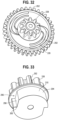
- the clutch 290 includes at least one spring finger 292, and preferably a plurality of spring fingers (shown as two).
- the driven member, or gear or pulley may include in one embodiment a hub 294 having at least one indentation 296, and preferably a number of indentations 296 (e.g., 2) corresponding to the number of spring fingers 292, although the numbers may be different.
- the spring fingers 292, which are in-molded with the spur gear 339 in one embodiment, may be configured as cantilever leaf springs having a curved arm 302 extending from web of the spur gear 339 and terminating at an engagement end 304.
- the engagement end 304 is positioned radially inwardly from an inner bearing surface 306 of the driven gear, or spur gear 339, when the arm 302 is in a non-biased position, i.e., is not pre-loaded.
- the arm 302 is preloaded by moving the end 304 radially outwardly until it engages an outer bearing surface 310 of the hub 294, or shaft, of the pinion gear 338.
- the indentations 296 are formed and extend radially inwardly form the bearing surface 310.
- the indentations include a ramped surface 298 tapering inwardly from and intersecting the bearing surface 310 and a stop surface 300 extending from and intersecting the ramped surface 298 toward and intersecting the bearing surface 310.
- the stop surface 300 is substantially orthogonal to a tangent of the bearing surface 310, and the intersection thereof, in one embodiment, although other angles may be suitable.
- the arm 302 biases the engagement end 304 into engagement with the indentation 296, and the surfaces 298 and 300 in particular, due to the preload.
- the arms 302, and the ends 304 thereof will eventually engaged the stop surface 300 as the arm is biased radially inwardly and thereafter drive the driven gear, or spur gear 339 with the drive gear 338 as the chain wheel 21 is rotated in one rotation direction, i.e., a pedaling direction.
- the spring fingers 292, or curved arm 302 is biased into engagement with the indentation 296, and the stop surface 300, when the chain pulley 21 is rotated in the first rotational direction, and wherein the spring fingers 292, or curved arm 302, is biased out of engagement with the indentation 296 by the ramped surface 298 and bearing surface 310 when the chain pulley 21 is rotated in the second rotational direction such that the generator 50 is deactivated, or not rotated.
- a belt tensioner 320 may be coupled to the cage assembly and is operable to adjust a tension of the belt 43.
- the belt tensioner 320 includes a first fastener 51, or first generator screw, which is threadably engaged with a first boss 24a formed on the outer cage 24, and a second fastener 52, or second generator screw, which is threadably engaged with a second boss 24b formed on the outer cage 24.
- the first fastener 51 passes through an opening in the generator base 46
- the second fastener 52 passes through a washer 53 overlapping an edge of the generator base 46.
- the belt tensioner 320 further includes a belt tension adjustment member 54 that acts between the outer cage 24 and the generator 50, and the base 46 in particular.
- the adjustment member 54 may be configured as a set screw, which is threadably received in a boss 24b formed in the outer cage 24. An end 322 of the adjustment member 54 abuts the generator base 46, for example an edge thereof.
- the adjustment member 54 may then be actuated, for example by threadably engaging the upper boss 24b, such that the adjustment member 54 pushes on the edge of generator base 46 against a biasing force or tension of the belt 43.
- the base 46 may rotate slightly around the fastener 51, creating more tension in the belt 43.
- the fasteners 51, 52 may be tightened, thus fixing the belt tension at the desired level.
- the adjustment member 54 may be provided with an anti-loosening device, for example a nylon patch to prevent loosening of the adjustment member 54 over time.
- a plurality of generator wires 49 extend from the stator 48 of the generator.
- the generator wires 49 are electrically connected to a generator printed circuit board (generator PCB) 55, which is mounted to the housing 200.
- generator PCB 55 is secured to the outer cage 24 with a screw 56, although the PCB 55 may be secured with adhesives, a snap fit or other suitable fasteners.
- the PCB 55 may alternatively be secured to the cover 23.
- a main printed circuit board (main PCB) 57 is fixed relative to housing 200, for example the cover 23, by a first mounting screw 80 and a second motor holder mounting screw 78.
- the main PCB 57 includes various electronic components, including but not limited to a power storage device 57d, configured in one embodiment as supercapacitors, a motor driver 57f, an encoder 57e, a switch 57b, an LED 57c, a plurality of pogo pins 57a, and a microcontroller 402.
- the pogo pins 57a of the main PCB 57 are in electrical contact with the generator PCB 55.
- the energy storage device 57d e.g., supercapacitors, also is coupled to and moveable with the cage assembly 9, and in particular is secured to the main PCB 57.
- the generator 50 generates energy which is transmitted to and stored in the energy storage device 57d.
- the energy storage device 57d includes at least one capacitor, shown as two supercapacitors.
- the energy storage device may include one or more batteries, for example rechargeable batteries.
- a function button 19 is coupled to the housing 200, and cover 23 in particular, by a button retainer 59.
- An elastomeric seal 58 is disposed between the button retainer 59 and a surface of the cover 23, or housing 200.
- the button 19 When the function button 19 is pressed by the user, the button 19 actuates the switch 57b of the main PCB 57.
- the function button 19 may be used to wirelessly pair the derailleur 180 with other system components, such as shifters that may located remotely on the handle bars, for example.
- a LED lens 20 may be a clear lens that is fixed in a hole in the cover 23 or cage 24, i.e. housing 200.
- the LED lens 20 is positioned such that LED 57c of the main PCB 57 shines through the lens 20 and is visible to the user.
- the LED 57c may be used to indicate a state of the system.
- the LED 57c is used when wirelessly pairing derailleur 180 with other system components, such as the shifters.
- the LED 57c also may also be used to indicate other system states, such as battery life, for example.
- the crank arm 92 has a cylindrical recess 92a, a first hole 92b and a second hole 92c.
- the crank arm 92 is rotatably connected to a fourth pin 18 at the second hole 92c.
- the spherical end 91b of lead nut 91 is engaged with the cylindrical recess 92a of the crank arm 92.
- the crank arm 92 includes a slot 92d, which cuts through cylindrical recess 92a and provides clearance for the elongated cylindrical portion of the lead nut 91 and lead screw 81.
- the outer link 6 is fixed to the fourth pin 18 with a fastener, for example a set screw 101, which engages a flat 18b formed on the fourth pin 18.
- a fastener for example a set screw 101, which engages a flat 18b formed on the fourth pin 18.
- a fastener 102 for example a screw, is threadably engaged with an end of the fourth pin 18.
- the saver spring 95 Prior to engaging the drive element 99 with the drive pin 97 disposed in the recess 99a of drive element 99, the saver spring 95 is in a "free,” or relaxed state.
- a tool such as a screwdriver bit, may be engaged with the fastener 102, e.g., by inserting the tool into a screw, and thereafter actuated to rotate the fourth pin 18 counterclockwise as shown in FIG. around the axis (C). Since the fourth pin 18 is fixed to the drive element 99, the drive element (99) is rotated with the pin 18.
- the surface 99c of the drive element 99 biases or pushes an end of the saver spring 95, so as to load or wind up the saver spring 95 from a "free", or relaxed, state to a preloaded state.
- the drive pin 97 may thereafter be slid into engagement with the recess 99a of the drive element 99.
- the tool may be removed, with the biasing force of the saver spring 95 biasing the surface 99b of the drive element 99 clockwise around the axis (C) against the drive pin 97.
- a cage spring 90 is formed as a torsion spring, a first end of which is disposed in a recess formed in the moveable member 8 and is engaged therewith. A second end of the spring 90 is engaged with the cover 23, and is disposed in a recess in the cover 23.
- the cage spring 90 is arranged to rotationally bias the cage assembly 9 in the clockwise direction around axis (B) as shown in FIG. 1 to take up any slack in the chain 4.
- a clutch spring 89 is shown as having a plurality of coils, for example in one embodiment with seven coils.
- the inner diameter of the a first plurality of coils e.g., approximately the first five coils, is wrapped around a cylindrical surface of the moveable member 8.
- the inner diameter of a second plurality of coils, or a single auxiliary coil, is wrapped around a cylindrical surface of the cage shaft 85, with the first plurality of coils being greater than the second plurality (or auxiliary) coils.
- the resulting drag of the cage shaft 85 against the clutch spring 89 causes the coils of the clutch spring 89 to loosen against the cylindrical surface of cage shaft 85, which acts to reduce friction and allow the cage assembly 9 to rotate more easily.
- the function of the clutch spring 89 is to resist undesired (counterclockwise around axis (B) rotation of the cage assembly 9, which may allow the chain 4 to become slack, for example when the bicycle is traveling over rough terrain.
- the transmission 250 provides for rotational power to flow from the first generator spur gear 37 to the first generator pinion gear 38 to the second generator spur gear 39 to the second generator pinion gear 40 to the first generator pulley 41 through the belt 43 to the second generator pulley 42 to the rotor 47 of the generator 50.
- Rotation of the rotor 47 relative to the stator 48 generates electrical power.
- the generated electrical power flows through the wires 49 of the generator 50 to the generator PCB 55, and thereafter through the pogo pins 57a into the main PCB 57, where it is stored in an storage device 57d, for example the supercapacitors or a battery.
- the storage device may thereafter supply power to the motor 60 to effect various shifting actions.
- the storage device 57d may supply power to other electrical devices and accessories, including those located remote to the derailleur, for example and without limitation a wheel speed sensor, a cassette speed sensor, a power meter, lights, the front derailleur, an adjustable seat post, and/or other types of bicycle accessories, or may supply power to the motor and to such auxiliary devices.
- power may be transmitted by various electrical connectors, e.g., wires.
- the energy storage device also may be located remote to the derailleur, for example with the energy storage device mounted on another part of the frame 2 or bicycle component, and joined to the generator with electrical connectors, e.g., wires.
- the interface of the pulleys 41, 42 and the belt 43 results in less noise than an equivalent spur and pinion gear interface.
- gears that rotate relatively slowly do not create as much noise that may be objectionable to the rider, whereas gears that rotate at a high revolution per minute (RPM) may create a highpitched noise that may be objectionable to the rider. Therefore, in one embodiment, the transmission may use gear interfaces when the angular velocities are relatively low, (i.e. close to the angular velocity of the upper pulley 21), and a pulley belt interface may be used when the angular velocity of the pulleys are relatively high (i.e. close to the angular velocity of the rotor 47).
- the rider operates a switch of a shifter on the handlebar.
- a wireless signal may be emitted from the shifter.
- the wireless signal is received by the antenna and radio on the main PCB 57.
- the signal is processed by the main PCB 57, and a controller provides for power to be transmitted from the power storage device 57d, e.g., the supercapacitors, to the motor 60.
- the power storage device 57d e.g., the supercapacitors
- power supply provides power to the motor 60, which rotates in the direction that, through the shifting drive system, including the drive pinion gears and spur gears 65-70, drives the third drive spur gear 70 and the lead screw 81 in a first rotational direction.
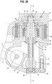
- the lead nut 91 is threadably engaged with the lead screw, but the lead nut 91 is unable to rotate relative to the cage shaft 85. Accordingly, the lead nut 91 moves axially along the axis (B) in the upwards direction, with reference to the orientation of FIG. 20 .
- the spherical end 91b of the lead nut 91 drives the crank arm 92 counterclockwise around the axis (C) of the fourth pin 18.
- the drive pin 97 engages the surface 99b of the drive element 99, thereby rotating the drive element 99 counterclockwise around the axis (C) of the fourth pin 18. Since the drive element 99 is fixed to the fourth pin 18, the fourth pin 18 also rotates counterclockwise. Since the fourth pin 18 also is fixed to the outer link 6, the outer link 6 also rotates counterclockwise around the axis (C), driving the linkage 186 in the inboard direction of the bicycle, which drives the moveable member 8 and the cage assembly 9 in the inboard direction. Since the chain 4 is engaged with upper chain pulley 21 of the cage assembly 9, the chain 4 also is driven in the inboard direction, causing the chain 4 to shift to the next larger sprocket or cog of the cassette 3.
- the power supply supplies power to the motor 60, which rotates in the direction that, through the shifting drive system, including the drive pinion gears and spur gears 65-70, drives the third drive spur gear 70 and the lead screw 81 in a second rotational direction, driving lead nut 91 to move axially along axis (B) in the downwards direction.
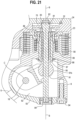
- the spherical end 91b of the lead nut 91 drives the crank arm 92 clockwise in FIG. 21 around the axis (C) of the fourth pin 18.
- the crank arm 92 drives the saver spring 95 clockwise around axis (C) of the fourth pin 18.
- the saver spring 95 drives the drive element 99 clockwise around axis (C) of the fourth pin 18. Since the drive element 99 is fixed to the fourth pin 18, the fourth pin 18 also rotates clockwise. Since the fourth pin 18 is fixed to the outer link 6, the outer link 6 also rotates clockwise around axis (C), driving the parallelogram linkage 186 in the outboard direction of the bicycle, which drives the moveable member 8 and the cage assembly 9 in the outboard direction. Since the chain 4 is engaged with upper chain pulley 21 of the cage assembly 9, the chain 4 is also driven in the outboard direction, causing the chain 4 to shift into the next smaller sprocket or cog of the cassette 3.
- the encoder 57e on the main PCB 57 together with encoder magnet (72), are used to provide positional feedback of the moveable member 8, the cage assembly 9 and the chain pulley 21.
- the encoder gear 71 is engaged with first drive spur gear 66.
- the gear 66 causes the encoder gear 71, along with encoder magnet 72 to rotate about the axis of encoder gear 71.
- the encoder magnet 72 rotates relative to the encoder 57e.
- the encoder 57e outputs a signal that indicates the angular position of encoder magnet 72 relative to the encoder 57e.
- the encoder magnet 72 makes multiple complete revolutions.
- a controller on the main PCB 57 counts the number of times that encoder magnet 72 makes a complete revolution. Knowing the number of times that encoder magnet 72 has rotated, along with its current angular position relative to encoder 57e, the controller can calculate the current position of the moveable member 8 relative to the bicycle frame 2, and by extension the cassette 3.
- a predetermined shift table has multiple values, each of which corresponds to a shift position of derailleur 180. As the encoder magnet 72 rotates during a shifting operation, a value corresponding to the current position of the moveable member 8 is compared to a target value in the table, with the controller capable or operable to determine when the moveable member 8 has reached its target position (i.e. the gear selected by the rider).
- a homing routine may be performed.
- the derailleur 180 positions the crank arm 92 at a reference position, and sets the corresponding angular position indicated by encoder 57e as a reference value.
- the lead nut 91 is driven downwards, driving the crank arm 92 clockwise around axis (C) until contact between the crank arm 92 and a moveable member cover 93 prevents further clockwise rotation of the crank arm 92.
- the corresponding positional value output by the encoder 57e is established as a reference value.
- this homing routine is performed at the factory when the derailleur 180 is assembled, but the routine may also be performed after derailleur 180 is installed on a bicycle.
- the homing routine may be performed even when the moveable member 8 is physically prevented from moving (i.e. when the rider isn't pedaling and the presence of the chain 4 prevents movement of the moveable member 8).
- the crank arm 92 can still rotate clockwise to the position shown in FIG. 20 by winding up the saver spring 95.
- the crank arm 92 may be driven to its reference position and the homing operation can be performed, even if movement of the moveable member 8 is blocked.
- the saver spring 95 acts as a safety clutch during impacts.
- the drive element 99 will be driven in the counterclockwise direction around axis (C). If the external force exceeds the preload of the saver spring 95, the drive element 99 will wind up the saver spring 95, preventing excessive force from being transmitted to the lead nut 91. When the external force is removed, the saver spring 95 will unwind to its previous position.
- a schematic shows one embodiment of a control system for the generator 50, motor 60 and shifting drive system 330.
- the chain pulley 21 rotates the generator 50 which creates an alternating current (AC) voltage across each set of coils within the generator 50.
- the coils are connected to a rectification circuit 400 formed by diodes D1, D2, D3, D4, D5 and D6, which rectify the voltage to direct current (DC).
- the generator 50 may be configured as a permanent magnet brushless type generator having a plurality of (e.g., three) sets of coils internally connected preferably in a star configuration, although a delta configuration may also be suitable.
- the generator 50 may also be constructed from any number of coils so long as the coils are connected to the rectification circuit 400 that creates a DC voltage.
- the generator 50 may also be of a brushed type which creates DC voltage mechanically.
- Capacitors C3 and C4 are incorporated into the circuit to create a better impedance match to the energy storage device 57d, e.g., storage capacitors C1 and C2.
- Diodes D7, D8 and resistors R9, R10 are used to sense the speed and direction of the generator 50 which may be used to determine the speed and rotational direction of the chain pulley 21 and therefore the speed and rotational direction of the chain 4.
- a memory contains information about the number of teeth of each sprocket or cog of the cassette 3.
- the encoder 57e provide a signal such that the controller, e.g., microcontroller 402, knows what gear is currently indexed.
- the microcontroller 402 is programmed with information about the number of teeth on chainring(s). If the bicycle has more than one chainring installed, the front chainring shifting system communicates the currently selected chainring to the rear derailleur 180 when the front chain ring is changed.
- the controller 402 on the rear derailleur 180 knows how fast the bicycle is travelling and how fast the rider is turning the cranks.
- the bicycle speed and cadence information may be used to perform an automatic shifting algorithm which keeps the gear ratio at a preferable ratio for the rider.
- the diode anode of each diode-resistor pair is connected to a signal input on the microcontroller 402 as well as to the digital voltage supply Vdd through a pull up resistor. When the individual phase voltages of the diodes D7 or D8 drop below the VDD, the diode will conduct to ground and register a low signal to the microcontroller 402.
- phase voltage exceeds VDD the diode will not conduct and the signal to the microcontroller 402 will be clamped to VDD through R9 or R10.
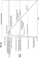
- the sequence of pulses from each phase are different if the generator 50 is spinning clockwise or counter clockwise, as shown in FIGS. 35A and B , and any change in frequency is based on how fast the generator 50 is turning and therefore how fast the rider is pedaling. These sequences can be recognized by timing order by the microcontroller 402.
- the microcontroller 402 may modify the charging behavior if the pulse train corresponds to forward or reverse pedaling, for instance it may be desirable to disable charging, or deactivate the generator, while backpedaling, for example with the clutch, to reduce slack in the chain 4, which may cause the chain to disengage from the sprockets. It may be desirable to only allow charging above a certain rider cadence, and/or it may be desirable to always have charging enabled while not pedaling to reduce chain slap, etc. One way to determine rotational direction is to look at the pulses read by the microcontroller 402 for two adjacent generator coils.
- the phase of the L2 and L3 signals are separated by 120 degrees (of time) followed by 240 degrees and the sequence repeats when the generator 50 is spinning at a constant speed.
- the order of pulses indicates direction. For instance, an L2 signal followed by 120 degrees, then an L3 signal followed by 240 degrees and another L2 signal might indicate forward pedaling ( FIG. 35A ), where an L3 signal followed by 120 degrees then an L2 signal followed by 240 degrees followed by another L3 signal would indicate reverse pedaling ( FIG. 35B ).
- the actual generator speed is not likely to be perfectly constant in reality, but, because the generator 50 rotates many times for each turn of the cranks, analyzing the relative spacing of the L2, L3 sequence will be valid.
Landscapes
- Engineering & Computer Science (AREA)
- Chemical & Material Sciences (AREA)
- Combustion & Propulsion (AREA)
- Transportation (AREA)
- Mechanical Engineering (AREA)
- Connection Of Motors, Electrical Generators, Mechanical Devices, And The Like (AREA)
- Devices For Conveying Motion By Means Of Endless Flexible Members (AREA)
- Permanent Magnet Type Synchronous Machine (AREA)
- Transmission Devices (AREA)
Claims (9)
- Fahrradumwerfer (180) umfassend:ein Basiselement (5), das an einem Fahrradrahmen (2) anbringbar ist; undeine Käfiganordnung (9), die bewegbar mit dem Basiselement (5) gekoppelt ist, wobei die Käfiganordnung (9) in eine erste und entgegengesetzte zweite Richtung relativ zu dem Basiselement (5) bewegbar ist;dadurch gekennzeichnet, dass der Fahrradumwerfer (180) ferner einen Motor (60) umfasst, der mit der Käfiganordnung (9) gekoppelt ist und mit dieser in die erste und entgegengesetzte zweite Richtung bewegbar ist, wobei der Motor (60) dazu dient, die Käfiganordnung (9) in die erste und entgegengesetzte zweite Richtung zu bewegen, wobei der Motor (60) an der Käfiganordnung (9) angebracht ist.
- Fahrradumwerfer (180) nach Anspruch 1, ferner umfassend ein bewegliches Element (8), das mit einer Verbindungsanordnung (186) bewegbar an das Basiselement (5) gekoppelt ist, und wobei die Käfiganordnung (9) drehbar an das bewegliche Element (8) gekoppelt ist,wobei die Verbindungsanordnung (186) optional erste und zweite Verbindungen (6,7) umfasst, die sich zwischen dem Basiselement (5) und dem beweglichen Element (8) erstrecken, wobei das Basiselement (5), erste und zweite Verbindungen (6,7) und das bewegliche Element (8) ein Gelenkviereck definieren,wobei ferner optional die Käfiganordnung (9) drehbar an das bewegliche Element (8) um eine sich seitlich erstreckende Achse (B) gekoppelt ist.
- Fahrradumwerfer (180) nach Anspruch 1 oder 2, ferner umfassend ein elektrisches Generatorsystem (240), das an die Käfiganordnung (9) gekoppelt ist und mit dieser bewegbar verbunden ist, wobei das elektrische Generatorsystem (240) den Motor (60) mit Strom versorgt,wobei das elektrische Generatorsystem (240) optional einen Generator (50) und eine Energiespeichervorrichtung (57d) umfasst, wobei der Generator (50) Energie erzeugt, die in der Energiespeichervorrichtung (57d) gespeichert wird und wobei der Motor (60) elektrisch an die Energiespeichervorrichtung (57d) gekoppelt ist und von dieser mit Strom versorgt wird,wobei die Energiespeichervorrichtung (57d) ferner optional wenigstens einen Kondensator umfasst.
- Fahrradumwerfer (180) nach Anspruch 3, wobei die Käfiganordnung (9) ein Gehäuse (200) umfasst, und wobei das elektrische Generatorsystem (240) ein Generatorantriebssystem (244) umfasst, das an den Generator (50) gekoppelt ist, wobei das Generatorantriebssystem (244) eine Kettenschaltrolle (21) umfasst, die drehbar um eine erste Drehachse an das Gehäuse (200) gekoppelt ist, wobei das Generatorantriebssystem (244) optional ein Generatorgetriebe (250) umfasst, das funktionsfähig zwischen der Kettenschaltrolle (21) und dem Generator (50) gekoppelt ist.
- Fahrradumwerfer (180) nach Anspruch 4, wobei die Kettenschaltrolle (21) eine erste Drehzahl und der Generator (50) eine zweite Drehzahl aufweist, wobei das Generatorgetriebe (250) ein Verhältnis zwischen der ersten und der zweiten Drehzahl von 20:1 bis 50:1 bereitstellt,
wobei das Generatorgetriebe (250) optional wenigstens eine erste und zweite Schaltrolle (41,42) umfasst, die jeweils drehbar um die zweite und dritte Drehachse an das Gehäuse (200) gekoppelt sind und einen Riemen (43), der mit der ersten und zweiten Schaltrolle (41,42) in Eingriff steht, wobei die erste und die zweite Schaltrolle (41,42) ein Schaltrollenverhältnis größer 1 aufweisen. - Fahrradumwerfer (180) nach Anspruch 5, ferner umfassend einen Riemenspanner (320), der an das Gehäuse (200) gekoppelt ist und der zum Einstellen der Spannung des Riemens (43) dient.
- Fahrradumwerfer (180) nach Anspruch 6, wobei das Generatorgetriebe (250) ferner ein erstes Stirnrad, das an der Kettenschaltrolle (21) befestigt ist und mit dieser um die erste Drehachse drehbar ist, ein erstes Ritzel, das mit dem ersten Stirnrad in Eingriff steht und um eine vierte Drehachse drehbar ist, die von der ersten Drehachse beabstandet ist, ein zweites Stirnrad, das an dem ersten Ritzel befestigt ist und mit diesem um die vierte Drehachse drehbar ist und ein zweites Ritzel, das mit dem zweiten Stirnrad in Eingriff steht und um eine zweite Drehachse drehbar ist, die von der vierten Drehachse beabstandet ist, umfasst, wobei die erste Schaltrolle (41) an dem zweiten Ritzel befestigt ist und mit dieser um die vierte Drehachse drehbar ist und wobei der Generator (50) einen Rotor umfasst, der an der zweiten Schaltrolle (42) befestigt ist und mit der zweiten Schaltrolle (42) um die dritte Drehachse drehbar ist.
- Fahrradumwerfer (180) nach Anspruch 6 oder 7, wobei das Generatorgetriebe (250) ein Antriebselement umfasst, das eine zweite Drehachse und ein Getriebe, das eine Kupplung (290) umfasst, die koaxial an dem Antriebselement angebracht ist, definiert, wobei die Kupplung (290) für einen einseitigen Dreheingriff zwischen dem Antriebselement und dem Getriebe sorgt, wobei das Getriebe mit dem Antriebselement in eine erste Drehrichtung des Antriebselements drehbar ist und wobei das Antriebselement relativ zu dem Getriebe in eine zweite Drehrichtung des Antriebselements entgegengesetzt der ersten Drehrichtung drehbar ist.
- Fahrradumwerfer (180) nach Anspruch 2 und einem der vorangehenden Ansprüche, ferner umfassend ein Schaltantriebssystem (330), das zwischen dem Motor (60) und dem Gestänge (186) gekoppelt ist, wobei das Schaltantriebssystem (330) einen Antrieb vom Motor (60) und einen mit dem Gestänge (186) gekoppelten Abtrieb umfasst,wobei der Abtrieb optional eine Leitspindel (81) umfasst, die in die erste und entgegengesetzte zweite Drehrichtung drehbar ist, wobei die Leitspindel (81) gewindemäßig mit einem Kurbelarm (92) in Eingriff steht, wobei der Kurbelarm (92) in die erste und entgegengesetzte zweite axiale Richtung als Reaktion auf die Drehung der Leitspindel (81) in die erste und entgegengesetzte zweite Drehrichtung bewegbar ist und wobei der Kurbelarm (92) an die Verbindungsanordnung (186) gekoppelt ist,wobei der Antrieb ferner optional eine erste Drehzahl aufweist und wobei der Abtrieb eine zweite Drehzahl aufweist, wobei die erste Drehzahl größer ist als die zweite Drehzahl.
Applications Claiming Priority (1)
| Application Number | Priority Date | Filing Date | Title |
|---|---|---|---|
| US17/314,949 US11713095B2 (en) | 2021-05-07 | 2021-05-07 | Bicycle derailleur |
Publications (3)
| Publication Number | Publication Date |
|---|---|
| EP4086153A2 EP4086153A2 (de) | 2022-11-09 |
| EP4086153A3 EP4086153A3 (de) | 2023-01-25 |
| EP4086153B1 true EP4086153B1 (de) | 2024-12-18 |
Family
ID=81585363
Family Applications (1)
| Application Number | Title | Priority Date | Filing Date |
|---|---|---|---|
| EP22172003.0A Active EP4086153B1 (de) | 2021-05-07 | 2022-05-06 | Fahrradumwerfer |
Country Status (5)
| Country | Link |
|---|---|
| US (2) | US11713095B2 (de) |
| EP (1) | EP4086153B1 (de) |
| CN (2) | CN118004324A (de) |
| DE (1) | DE102022111279A1 (de) |
| TW (3) | TWI843089B (de) |
Families Citing this family (6)
| Publication number | Priority date | Publication date | Assignee | Title |
|---|---|---|---|---|
| US9394030B2 (en) * | 2012-09-27 | 2016-07-19 | Sram, Llc | Rear derailleur |
| US11428279B2 (en) * | 2018-11-26 | 2022-08-30 | Fox Factory, Inc. | Suspension enhancing hub and rear derailleur assembly |
| US12384491B2 (en) * | 2021-05-07 | 2025-08-12 | Sram, Llc | Bicycle derailleur |
| US11713095B2 (en) * | 2021-05-07 | 2023-08-01 | Sram, Llc | Bicycle derailleur |
| ES2944606B2 (es) * | 2021-12-22 | 2024-04-17 | Ojmar Sa | Metodo y sistema mecatronico de activacion en cascada |
| US12275491B2 (en) * | 2023-08-28 | 2025-04-15 | Shimano Inc. | Bicycle motor unit and bicycle derailleur |
Family Cites Families (59)
| Publication number | Priority date | Publication date | Assignee | Title |
|---|---|---|---|---|
| US3919891A (en) * | 1973-10-15 | 1975-11-18 | Brian J Stuhlmuller | Electrical gear changer for chain driven vehicle |
| DE3631481A1 (de) * | 1986-09-16 | 1988-05-05 | Villiger Soehne Ag | Elektromechanische fahrrad-gangschaltung |
| DE4109006A1 (de) | 1991-03-19 | 1992-09-24 | Stefan E Metzner | An der antriebskette angetriebener stromgenerator (dynamo) fuer fahrraeder |
| IT1261090B (it) | 1993-07-08 | 1996-05-08 | Antonio Romano | Gruppo di cambio di velocita' motorizzato per biciclette. |
| US5494307A (en) * | 1993-09-09 | 1996-02-27 | Anderson; Paul M. | Gear shifting apparatus |
| IT1266817B1 (it) | 1994-02-24 | 1997-01-21 | Campagnolo Srl | Dispositivo di cambio di velocita' per biciclette. |
| WO1995026900A1 (fr) * | 1994-04-05 | 1995-10-12 | Edco Engineering S.A. | Dispositif de selection de rapports pour engins mus par la force musculaire, notamment pour bicyclette |
| US6162140A (en) * | 1998-12-18 | 2000-12-19 | Shimano, Inc. | Motor driven derailleur |
| US7290458B2 (en) * | 2004-02-24 | 2007-11-06 | Shimano, Inc. | Bicycle derailleur with a motor disposed within a linkage mechanism |
| US7467567B2 (en) * | 2004-02-24 | 2008-12-23 | Shimano, Inc. | Gear reduction apparatus for a bicycle component |
| US8137223B2 (en) * | 2007-05-16 | 2012-03-20 | Shimano Inc. | Bicycle rear derailleur |
| US8721495B2 (en) * | 2011-06-17 | 2014-05-13 | Shimano Inc. | Rear derailleur and gear shift system |
| US10220913B2 (en) | 2011-06-17 | 2019-03-05 | Shimano Inc. | Bicycle chain tensioner device |
| US9428246B2 (en) | 2011-12-09 | 2016-08-30 | Shimano Inc. | Bicycle generator and/or shifting device |
| US9303763B2 (en) * | 2012-12-10 | 2016-04-05 | Shimano, Inc | Bicycle rear derailleur |
| US9005059B2 (en) * | 2013-03-27 | 2015-04-14 | Shimano Inc. | Rear derailleur |
| US9676444B2 (en) * | 2013-10-23 | 2017-06-13 | Sram, Llc | Electromechanical rear derailleur |
| ITPD20130301A1 (it) | 2013-11-08 | 2015-05-09 | Claudio Tiso | Dispositivo autoalimentato di cambio dei rapporti di trasmissione per biciclette |
| US9334017B2 (en) * | 2014-03-14 | 2016-05-10 | Tien Hsin Industries Co., Ltd. | Electronic rear derailleur |
| US9776684B2 (en) * | 2014-10-17 | 2017-10-03 | Tektro Technology Corporation | Derailleur |
| ITMI20142069A1 (it) * | 2014-12-02 | 2016-06-02 | Campagnolo Srl | Deragliatore di un cambio di bicicletta e metodo per controllare elettronicamente un cambio di bicicletta |
| ITMI20142070A1 (it) * | 2014-12-02 | 2016-06-02 | Campagnolo Srl | Deragliatore di un cambio di bicicletta e metodo per controllare elettronicamente un cambio di bicicletta |
| US9963197B2 (en) * | 2015-10-26 | 2018-05-08 | Shimano Inc. | Electric bicycle rear derailleur |
| US10370060B2 (en) * | 2015-10-30 | 2019-08-06 | Shimano Inc. | Bicycle electrical component assembly |
| DE202015003858U1 (de) * | 2015-05-28 | 2015-06-30 | Hans-Peter Blatt | Kettenfahrradschaltung mit Steuerkopf und Stirnzahnrädern, welche mit oder ohne elektr. Motor funk- bzw. manuell gesteuert über eine verbundene Schaltwelle rotatorische Bewegungen mittels eines Parallelogramm ähnlichen Schaltarmes in radiale Schaltvorgänge wandelt |
| US9656723B1 (en) * | 2015-12-14 | 2017-05-23 | Shimano Inc. | Electrical bicycle derailleur |
| IT201600131314A1 (it) * | 2016-12-27 | 2018-06-27 | Campagnolo Srl | Deragliatore elettronico wireless di bicicletta |
| US10875601B2 (en) * | 2017-02-10 | 2020-12-29 | Sram, Llc | Bicycle derailleur and connection |
| IT201700018702A1 (it) * | 2017-02-20 | 2018-08-20 | Campagnolo Srl | Deragliatore elettrico posteriore di bicicletta |
| US10793222B1 (en) * | 2017-03-21 | 2020-10-06 | Jonathan K. Harris | Bicycle derailleur having upper and lower alignment assemblies |
| US10773773B2 (en) * | 2017-06-07 | 2020-09-15 | Shimano Inc. | Electric bicycle derailleur |
| US10343748B2 (en) * | 2017-07-19 | 2019-07-09 | Th Industries Co., Ltd. | Electronic rear derailleur for bicycle |
| TWI644831B (zh) * | 2017-07-26 | 2018-12-21 | 鄭仲瑞 | Bicycle self-powered automatic transmission |
| US11110993B2 (en) * | 2017-09-13 | 2021-09-07 | Brandon Rodgers | Damping device adapted for integration within a gearshifting system |
| US10894574B2 (en) | 2017-10-02 | 2021-01-19 | Sram, Llc | Bicycle rear derailleur |
| US10981625B2 (en) * | 2017-10-02 | 2021-04-20 | Sram, Llc | Bicycle rear derailleur |
| US11428279B2 (en) * | 2018-11-26 | 2022-08-30 | Fox Factory, Inc. | Suspension enhancing hub and rear derailleur assembly |
| US11498643B2 (en) | 2019-02-26 | 2022-11-15 | Shimano Inc. | Bicycle electric derailleur |
| TWI723397B (zh) * | 2019-03-19 | 2021-04-01 | 彥豪金屬工業股份有限公司 | 自行車後變速器 |
| US11046390B2 (en) * | 2019-03-25 | 2021-06-29 | Hazem Nihad Hamed | Automatic bicycle shifter and electrical derailleur |
| DE102019204885A1 (de) | 2019-04-05 | 2020-10-08 | Shimano Inc. | Fahrradschaltwerk |
| DE102020000827A1 (de) * | 2019-04-25 | 2020-10-29 | Sram Deutschland Gmbh | Elektromechanisches Schaltwerk zur koaxialen Montage |
| US11608139B2 (en) | 2019-05-13 | 2023-03-21 | Shimano Inc. | Bicycle rear derailleur |
| US11535339B2 (en) | 2019-08-30 | 2022-12-27 | Shimano Inc. | Bicycle derailleur |
| TWI719705B (zh) * | 2019-11-06 | 2021-02-21 | 天心工業股份有限公司 | 自行車之後變速器 |
| TWI729557B (zh) * | 2019-11-06 | 2021-06-01 | 天心工業股份有限公司 | 自行車之後變速器 |
| TWI729556B (zh) * | 2019-11-06 | 2021-06-01 | 天心工業股份有限公司 | 自行車之後變速器 |
| ES1241315Y (es) * | 2019-11-21 | 2020-07-29 | Zuma Innovation S L | Desviador trasero con accionamiento flotante inalambrico |
| US11697474B2 (en) * | 2020-06-30 | 2023-07-11 | Shimano Inc. | Bicycle derailleur and link pin for bicycle derailleur |
| US11926394B2 (en) * | 2020-09-11 | 2024-03-12 | Shimano Inc. | Bicycle derailleur |
| IT202000031877A1 (it) * | 2020-12-22 | 2022-06-22 | Campagnolo Srl | Dispositivo attuatore per un cambio di bicicletta e relativo cambio di bicicletta |
| US11987324B2 (en) * | 2021-04-12 | 2024-05-21 | Sram, Llc | Damper for a bicycle component |
| US11713095B2 (en) * | 2021-05-07 | 2023-08-01 | Sram, Llc | Bicycle derailleur |
| US12384491B2 (en) * | 2021-05-07 | 2025-08-12 | Sram, Llc | Bicycle derailleur |
| CN218141972U (zh) * | 2021-06-29 | 2022-12-27 | Sram德国有限公司 | 自行车换挡机构及用于自行车换挡机构的马达传动单元 |
| US12240562B2 (en) * | 2021-06-30 | 2025-03-04 | Shimano (Singapore) Pte. Ltd. | Derailleur for human-powered vehicle |
| IT202100024737A1 (it) * | 2021-09-28 | 2023-03-28 | Campagnolo Srl | Deragliatore elettrico/elettronico di bicicletta a parallelogramma articolato |
| TWI822490B (zh) * | 2022-11-25 | 2023-11-11 | 彥豪金屬工業股份有限公司 | 自行車後變速器及自行車元件的傳動組件 |
| TWI848488B (zh) * | 2022-12-28 | 2024-07-11 | 彥豪金屬工業股份有限公司 | 自行車後變速器 |
-
2021
- 2021-05-07 US US17/314,949 patent/US11713095B2/en active Active
-
2022
- 2022-04-19 TW TW111114868A patent/TWI843089B/zh active
- 2022-04-19 TW TW113115114A patent/TW202430426A/zh unknown
- 2022-04-19 TW TW112131705A patent/TWI882418B/zh active
- 2022-05-05 CN CN202410341831.9A patent/CN118004324A/zh active Pending
- 2022-05-05 CN CN202210478949.7A patent/CN115303406B/zh active Active
- 2022-05-06 EP EP22172003.0A patent/EP4086153B1/de active Active
- 2022-05-06 DE DE102022111279.9A patent/DE102022111279A1/de active Pending
-
2023
- 2023-05-31 US US18/326,454 patent/US12420890B2/en active Active
Also Published As
| Publication number | Publication date |
|---|---|
| US11713095B2 (en) | 2023-08-01 |
| TWI843089B (zh) | 2024-05-21 |
| TW202348491A (zh) | 2023-12-16 |
| US20220355900A1 (en) | 2022-11-10 |
| TWI882418B (zh) | 2025-05-01 |
| US12420890B2 (en) | 2025-09-23 |
| CN115303406B (zh) | 2024-11-08 |
| DE102022111279A1 (de) | 2022-11-10 |
| EP4086153A3 (de) | 2023-01-25 |
| EP4086153A2 (de) | 2022-11-09 |
| US20230312054A1 (en) | 2023-10-05 |
| CN118004324A (zh) | 2024-05-10 |
| TW202430426A (zh) | 2024-08-01 |
| CN115303406A (zh) | 2022-11-08 |
| TW202243953A (zh) | 2022-11-16 |
Similar Documents
| Publication | Publication Date | Title |
|---|---|---|
| EP4086153B1 (de) | Fahrradumwerfer | |
| US12384491B2 (en) | Bicycle derailleur | |
| CN110605938B (zh) | 自行车传动系统 | |
| CN108100145B (zh) | 自行车曲柄组件 | |
| US20170219066A1 (en) | Bicycle driving device | |
| EP1452439B1 (de) | Steuerungseinrichtung für eine Fahrradgangschaltung | |
| EP2535254B1 (de) | Fahrradketten-Spannvorrichtung | |
| CN106064663A (zh) | 用于自行车的控制系统 | |
| CN105936325A (zh) | 自行车传动设备 | |
| EP1452440B1 (de) | Steuerungseinrichtung für eine Fahrradgangschaltung | |
| CN105936320B (zh) | 自行车变速设备 | |
| CN115723474B (zh) | 用于人力车辆的轮毂组件 | |
| EP4309989A1 (de) | Fahrradkettenschaltung | |
| US20250121911A1 (en) | Control device for human-powered vehicle | |
| US11813891B2 (en) | Hub for human-powered vehicle | |
| US12103633B2 (en) | Hub-assembly for human-powered vehicle | |
| EP4667343A2 (de) | Mehrgang-antriebseinheit für ein elektrofahrrad | |
| US20220388333A1 (en) | Hub assembly for human-powered vehicle |
Legal Events
| Date | Code | Title | Description |
|---|---|---|---|
| PUAI | Public reference made under article 153(3) epc to a published international application that has entered the european phase |
Free format text: ORIGINAL CODE: 0009012 |
|
| STAA | Information on the status of an ep patent application or granted ep patent |
Free format text: STATUS: REQUEST FOR EXAMINATION WAS MADE |
|
| 17P | Request for examination filed |
Effective date: 20220506 |
|
| AK | Designated contracting states |
Kind code of ref document: A2 Designated state(s): AL AT BE BG CH CY CZ DE DK EE ES FI FR GB GR HR HU IE IS IT LI LT LU LV MC MK MT NL NO PL PT RO RS SE SI SK SM TR |
|
| PUAL | Search report despatched |
Free format text: ORIGINAL CODE: 0009013 |
|
| AK | Designated contracting states |
Kind code of ref document: A3 Designated state(s): AL AT BE BG CH CY CZ DE DK EE ES FI FR GB GR HR HU IE IS IT LI LT LU LV MC MK MT NL NO PL PT RO RS SE SI SK SM TR |
|
| RIC1 | Information provided on ipc code assigned before grant |
Ipc: B62M 9/124 20100101ALI20221220BHEP Ipc: B62M 9/1242 20100101ALI20221220BHEP Ipc: B62M 9/126 20100101ALI20221220BHEP Ipc: B62M 9/122 20100101AFI20221220BHEP |
|
| STAA | Information on the status of an ep patent application or granted ep patent |
Free format text: STATUS: EXAMINATION IS IN PROGRESS |
|
| 17Q | First examination report despatched |
Effective date: 20240205 |
|
| GRAP | Despatch of communication of intention to grant a patent |
Free format text: ORIGINAL CODE: EPIDOSNIGR1 |
|
| STAA | Information on the status of an ep patent application or granted ep patent |
Free format text: STATUS: GRANT OF PATENT IS INTENDED |
|
| INTG | Intention to grant announced |
Effective date: 20240715 |
|
| GRAS | Grant fee paid |
Free format text: ORIGINAL CODE: EPIDOSNIGR3 |
|
| GRAA | (expected) grant |
Free format text: ORIGINAL CODE: 0009210 |
|
| STAA | Information on the status of an ep patent application or granted ep patent |
Free format text: STATUS: THE PATENT HAS BEEN GRANTED |
|
| AK | Designated contracting states |
Kind code of ref document: B1 Designated state(s): AL AT BE BG CH CY CZ DE DK EE ES FI FR GB GR HR HU IE IS IT LI LT LU LV MC MK MT NL NO PL PT RO RS SE SI SK SM TR |
|
| REG | Reference to a national code |
Ref country code: CH Ref legal event code: EP |
|
| REG | Reference to a national code |
Ref country code: DE Ref legal event code: R096 Ref document number: 602022008740 Country of ref document: DE |
|
| REG | Reference to a national code |
Ref country code: IE Ref legal event code: FG4D |
|
| REG | Reference to a national code |
Ref country code: NL Ref legal event code: FP |
|
| REG | Reference to a national code |
Ref country code: LT Ref legal event code: MG9D |
|
| PG25 | Lapsed in a contracting state [announced via postgrant information from national office to epo] |
Ref country code: HR Free format text: LAPSE BECAUSE OF FAILURE TO SUBMIT A TRANSLATION OF THE DESCRIPTION OR TO PAY THE FEE WITHIN THE PRESCRIBED TIME-LIMIT Effective date: 20241218 |
|
| PG25 | Lapsed in a contracting state [announced via postgrant information from national office to epo] |
Ref country code: FI Free format text: LAPSE BECAUSE OF FAILURE TO SUBMIT A TRANSLATION OF THE DESCRIPTION OR TO PAY THE FEE WITHIN THE PRESCRIBED TIME-LIMIT Effective date: 20241218 |
|
| PG25 | Lapsed in a contracting state [announced via postgrant information from national office to epo] |
Ref country code: BG Free format text: LAPSE BECAUSE OF FAILURE TO SUBMIT A TRANSLATION OF THE DESCRIPTION OR TO PAY THE FEE WITHIN THE PRESCRIBED TIME-LIMIT Effective date: 20241218 |
|
| PG25 | Lapsed in a contracting state [announced via postgrant information from national office to epo] |
Ref country code: NO Free format text: LAPSE BECAUSE OF FAILURE TO SUBMIT A TRANSLATION OF THE DESCRIPTION OR TO PAY THE FEE WITHIN THE PRESCRIBED TIME-LIMIT Effective date: 20250318 |
|
| PG25 | Lapsed in a contracting state [announced via postgrant information from national office to epo] |
Ref country code: GR Free format text: LAPSE BECAUSE OF FAILURE TO SUBMIT A TRANSLATION OF THE DESCRIPTION OR TO PAY THE FEE WITHIN THE PRESCRIBED TIME-LIMIT Effective date: 20250319 Ref country code: LV Free format text: LAPSE BECAUSE OF FAILURE TO SUBMIT A TRANSLATION OF THE DESCRIPTION OR TO PAY THE FEE WITHIN THE PRESCRIBED TIME-LIMIT Effective date: 20241218 |
|
| PG25 | Lapsed in a contracting state [announced via postgrant information from national office to epo] |
Ref country code: RS Free format text: LAPSE BECAUSE OF FAILURE TO SUBMIT A TRANSLATION OF THE DESCRIPTION OR TO PAY THE FEE WITHIN THE PRESCRIBED TIME-LIMIT Effective date: 20250318 |
|
| PGFP | Annual fee paid to national office [announced via postgrant information from national office to epo] |
Ref country code: NL Payment date: 20250421 Year of fee payment: 4 |
|
| REG | Reference to a national code |
Ref country code: AT Ref legal event code: MK05 Ref document number: 1752053 Country of ref document: AT Kind code of ref document: T Effective date: 20241218 |
|
| PG25 | Lapsed in a contracting state [announced via postgrant information from national office to epo] |
Ref country code: SM Free format text: LAPSE BECAUSE OF FAILURE TO SUBMIT A TRANSLATION OF THE DESCRIPTION OR TO PAY THE FEE WITHIN THE PRESCRIBED TIME-LIMIT Effective date: 20241218 |
|
| PG25 | Lapsed in a contracting state [announced via postgrant information from national office to epo] |
Ref country code: PL Free format text: LAPSE BECAUSE OF FAILURE TO SUBMIT A TRANSLATION OF THE DESCRIPTION OR TO PAY THE FEE WITHIN THE PRESCRIBED TIME-LIMIT Effective date: 20241218 |
|
| PGFP | Annual fee paid to national office [announced via postgrant information from national office to epo] |
Ref country code: DE Payment date: 20250409 Year of fee payment: 4 |
|
| PG25 | Lapsed in a contracting state [announced via postgrant information from national office to epo] |
Ref country code: ES Free format text: LAPSE BECAUSE OF FAILURE TO SUBMIT A TRANSLATION OF THE DESCRIPTION OR TO PAY THE FEE WITHIN THE PRESCRIBED TIME-LIMIT Effective date: 20241218 |
|
| PG25 | Lapsed in a contracting state [announced via postgrant information from national office to epo] |
Ref country code: IS Free format text: LAPSE BECAUSE OF FAILURE TO SUBMIT A TRANSLATION OF THE DESCRIPTION OR TO PAY THE FEE WITHIN THE PRESCRIBED TIME-LIMIT Effective date: 20250418 |
|
| PG25 | Lapsed in a contracting state [announced via postgrant information from national office to epo] |
Ref country code: PT Free format text: LAPSE BECAUSE OF FAILURE TO SUBMIT A TRANSLATION OF THE DESCRIPTION OR TO PAY THE FEE WITHIN THE PRESCRIBED TIME-LIMIT Effective date: 20250421 |
|
| PG25 | Lapsed in a contracting state [announced via postgrant information from national office to epo] |
Ref country code: EE Free format text: LAPSE BECAUSE OF FAILURE TO SUBMIT A TRANSLATION OF THE DESCRIPTION OR TO PAY THE FEE WITHIN THE PRESCRIBED TIME-LIMIT Effective date: 20241218 |
|
| PGFP | Annual fee paid to national office [announced via postgrant information from national office to epo] |
Ref country code: FR Payment date: 20250409 Year of fee payment: 4 |
|
| PG25 | Lapsed in a contracting state [announced via postgrant information from national office to epo] |
Ref country code: RO Free format text: LAPSE BECAUSE OF FAILURE TO SUBMIT A TRANSLATION OF THE DESCRIPTION OR TO PAY THE FEE WITHIN THE PRESCRIBED TIME-LIMIT Effective date: 20241218 Ref country code: AT Free format text: LAPSE BECAUSE OF FAILURE TO SUBMIT A TRANSLATION OF THE DESCRIPTION OR TO PAY THE FEE WITHIN THE PRESCRIBED TIME-LIMIT Effective date: 20241218 |
|
| PG25 | Lapsed in a contracting state [announced via postgrant information from national office to epo] |
Ref country code: SK Free format text: LAPSE BECAUSE OF FAILURE TO SUBMIT A TRANSLATION OF THE DESCRIPTION OR TO PAY THE FEE WITHIN THE PRESCRIBED TIME-LIMIT Effective date: 20241218 |
|
| PG25 | Lapsed in a contracting state [announced via postgrant information from national office to epo] |
Ref country code: CZ Free format text: LAPSE BECAUSE OF FAILURE TO SUBMIT A TRANSLATION OF THE DESCRIPTION OR TO PAY THE FEE WITHIN THE PRESCRIBED TIME-LIMIT Effective date: 20241218 |
|
| PG25 | Lapsed in a contracting state [announced via postgrant information from national office to epo] |
Ref country code: IT Free format text: LAPSE BECAUSE OF FAILURE TO SUBMIT A TRANSLATION OF THE DESCRIPTION OR TO PAY THE FEE WITHIN THE PRESCRIBED TIME-LIMIT Effective date: 20241218 |
|
| PG25 | Lapsed in a contracting state [announced via postgrant information from national office to epo] |
Ref country code: SE Free format text: LAPSE BECAUSE OF FAILURE TO SUBMIT A TRANSLATION OF THE DESCRIPTION OR TO PAY THE FEE WITHIN THE PRESCRIBED TIME-LIMIT Effective date: 20241218 |
|
| REG | Reference to a national code |
Ref country code: DE Ref legal event code: R097 Ref document number: 602022008740 Country of ref document: DE |
|
| PG25 | Lapsed in a contracting state [announced via postgrant information from national office to epo] |
Ref country code: DK Free format text: LAPSE BECAUSE OF FAILURE TO SUBMIT A TRANSLATION OF THE DESCRIPTION OR TO PAY THE FEE WITHIN THE PRESCRIBED TIME-LIMIT Effective date: 20241218 |
|
| PLBE | No opposition filed within time limit |
Free format text: ORIGINAL CODE: 0009261 |
|
| STAA | Information on the status of an ep patent application or granted ep patent |
Free format text: STATUS: NO OPPOSITION FILED WITHIN TIME LIMIT |
|
| REG | Reference to a national code |
Ref country code: CH Ref legal event code: L10 Free format text: ST27 STATUS EVENT CODE: U-0-0-L10-L00 (AS PROVIDED BY THE NATIONAL OFFICE) Effective date: 20251029 |
|
| 26N | No opposition filed |
Effective date: 20250919 |
|
| REG | Reference to a national code |
Ref country code: CH Ref legal event code: H13 Free format text: ST27 STATUS EVENT CODE: U-0-0-H10-H13 (AS PROVIDED BY THE NATIONAL OFFICE) Effective date: 20251223 |
|
| PG25 | Lapsed in a contracting state [announced via postgrant information from national office to epo] |
Ref country code: LU Free format text: LAPSE BECAUSE OF NON-PAYMENT OF DUE FEES Effective date: 20250506 |
|
| PG25 | Lapsed in a contracting state [announced via postgrant information from national office to epo] |
Ref country code: CH Free format text: LAPSE BECAUSE OF NON-PAYMENT OF DUE FEES Effective date: 20250531 |
|
| REG | Reference to a national code |
Ref country code: BE Ref legal event code: MM Effective date: 20250531 |
|
| PG25 | Lapsed in a contracting state [announced via postgrant information from national office to epo] |
Ref country code: MC Free format text: LAPSE BECAUSE OF FAILURE TO SUBMIT A TRANSLATION OF THE DESCRIPTION OR TO PAY THE FEE WITHIN THE PRESCRIBED TIME-LIMIT Effective date: 20241218 |
|
| PG25 | Lapsed in a contracting state [announced via postgrant information from national office to epo] |
Ref country code: IE Free format text: LAPSE BECAUSE OF NON-PAYMENT OF DUE FEES Effective date: 20250506 |
|
| PG25 | Lapsed in a contracting state [announced via postgrant information from national office to epo] |
Ref country code: BE Free format text: LAPSE BECAUSE OF NON-PAYMENT OF DUE FEES Effective date: 20250531 |