EP4086114B1 - Flugzeugsitzrückenlehnenbezug-befestigungssystem - Google Patents
Flugzeugsitzrückenlehnenbezug-befestigungssystem Download PDFInfo
- Publication number
- EP4086114B1 EP4086114B1 EP22171843.0A EP22171843A EP4086114B1 EP 4086114 B1 EP4086114 B1 EP 4086114B1 EP 22171843 A EP22171843 A EP 22171843A EP 4086114 B1 EP4086114 B1 EP 4086114B1
- Authority
- EP
- European Patent Office
- Prior art keywords
- seatback
- substrate
- cover
- attachment system
- frame
- Prior art date
- Legal status (The legal status is an assumption and is not a legal conclusion. Google has not performed a legal analysis and makes no representation as to the accuracy of the status listed.)
- Active
Links
Images


Classifications
-
- B—PERFORMING OPERATIONS; TRANSPORTING
- B60—VEHICLES IN GENERAL
- B60N—SEATS SPECIALLY ADAPTED FOR VEHICLES; VEHICLE PASSENGER ACCOMMODATION NOT OTHERWISE PROVIDED FOR
- B60N2/00—Seats specially adapted for vehicles; Arrangement or mounting of seats in vehicles
- B60N2/68—Seat frames
-
- B—PERFORMING OPERATIONS; TRANSPORTING
- B64—AIRCRAFT; AVIATION; COSMONAUTICS
- B64D—EQUIPMENT FOR FITTING IN OR TO AIRCRAFT; FLIGHT SUITS; PARACHUTES; ARRANGEMENT OR MOUNTING OF POWER PLANTS OR PROPULSION TRANSMISSIONS IN AIRCRAFT
- B64D11/00—Passenger or crew accommodation; Flight-deck installations not otherwise provided for
- B64D11/06—Arrangements of seats, or adaptations or details specially adapted for aircraft seats
- B64D11/0647—Seats characterised by special upholstery or cushioning features
-
- B—PERFORMING OPERATIONS; TRANSPORTING
- B60—VEHICLES IN GENERAL
- B60N—SEATS SPECIALLY ADAPTED FOR VEHICLES; VEHICLE PASSENGER ACCOMMODATION NOT OTHERWISE PROVIDED FOR
- B60N2/00—Seats specially adapted for vehicles; Arrangement or mounting of seats in vehicles
- B60N2/58—Seat coverings
- B60N2/5816—Seat coverings attachments thereof
- B60N2/5825—Seat coverings attachments thereof by hooks, staples, clips, snap fasteners or the like
-
- B—PERFORMING OPERATIONS; TRANSPORTING
- B60—VEHICLES IN GENERAL
- B60N—SEATS SPECIALLY ADAPTED FOR VEHICLES; VEHICLE PASSENGER ACCOMMODATION NOT OTHERWISE PROVIDED FOR
- B60N2/00—Seats specially adapted for vehicles; Arrangement or mounting of seats in vehicles
- B60N2/58—Seat coverings
- B60N2/5816—Seat coverings attachments thereof
- B60N2/5833—Seat coverings attachments thereof by hook-and-loop type fasteners
-
- B—PERFORMING OPERATIONS; TRANSPORTING
- B60—VEHICLES IN GENERAL
- B60N—SEATS SPECIALLY ADAPTED FOR VEHICLES; VEHICLE PASSENGER ACCOMMODATION NOT OTHERWISE PROVIDED FOR
- B60N2/00—Seats specially adapted for vehicles; Arrangement or mounting of seats in vehicles
- B60N2/58—Seat coverings
- B60N2/60—Removable protective coverings
- B60N2/6018—Removable protective coverings attachments thereof
- B60N2/6027—Removable protective coverings attachments thereof by hooks, staples, clips, snap fasteners or the like
-
- B—PERFORMING OPERATIONS; TRANSPORTING
- B60—VEHICLES IN GENERAL
- B60N—SEATS SPECIALLY ADAPTED FOR VEHICLES; VEHICLE PASSENGER ACCOMMODATION NOT OTHERWISE PROVIDED FOR
- B60N2/00—Seats specially adapted for vehicles; Arrangement or mounting of seats in vehicles
- B60N2/68—Seat frames
- B60N2/682—Joining means
Definitions
- the substrate may be formed of a thermoformed plastic or laminated fiberglass.
- the seatback frame may be configured to fit within the channel of the seatback cover attachment system.
- the seatback frame may be configured be inserted in the channel of the seatback cover attachment system.
- the seatback frame may be configured to engage with the substrate via a force applied in a direction downward from the channel of the seatback cover attachment system.
- the seatback frame may be configured to disengage from the substrate via a force applied in a direction upward from the channel of the seatback cover attachment system.
- FIGS. 1-8 in general illustrate an aircraft seatback cover attachment system, in accordance with one or more embodiments of the disclosure.
- the seatback cover may be subjected to stress, strain, dirt or other mess such as airsickness, contraband, or the like resulting in damage of the seatback cover. After a period of time and/or a particular type of wear factor occurring, the seatback cover may be removed for cleaning and/or replacement. Removing and re-installing the seatback cover may require a method that is quick, inexpensive, and not labor intensive. For example, the seatback cover attachment system should be quickly dismantled and put together without incurring considerable labor costs.
- the build of the seat may be required to meet guidelines and/or standards.
- aircraft seats may be required to meet aviation guidelines and/or standards.
- the select aircraft seats may need to be configured in accordance with aviation guidelines and/or standards put forth by, but not limited to, the Federal Aviation Administration (FAA), the European Aviation Safety Agency (EASA) or any other flight certification agency or organization; the American National Standards Institute (ANSI), Aeronautical Radio, Incorporated (ARINC), or any other standards setting organization or company; the Radio Technical Commission for Aeronautics (RTCA) or any other guidelines agency or organization; or the like.
- FAA Federal Aviation Administration
- EASA European Aviation Safety Agency
- ARINC Aeronautical Radio, Incorporated
- RTCA Radio Technical Commission for Aeronautics
- an aircraft seat 100 may be translatable (e.g., trackable or slidable).
- the aircraft seat 100 may be rotatable about an axis cross-wise through the aircraft seat 100 into a position including, but not limited to, the upright or raised position, one or more lounge or reclined positions, and a lie-flat or bed position.
- the aircraft seat 100 may transition directly between the upright or raised position and the lie-flat or bed position.
- the aircraft seat 100 may transition through one or more lounge or reclined positions between the upright or raised position and the lie-flat or bed position.
- the aircraft seat 100 may include a support system 102.
- the support system 102 may be a rigid structure within the aircraft seat 100, such that the support system 102 does not move.
- the support system 102 may include one or more movable components such that the support system 102 may articulate.
- the support system 102 may articulate when the aircraft seat 100 actuates between the upright or raised position, the one or more lounge or reclined positions, and/or the lie-flat or bed position.
- the seat pan cushion 104 may conform or substantially conform to the support system 102.
- at least one surface of the seat pan cushion 104 may conform to a corresponding surface of the support system 102.
- components of the support system 102 e.g., components including, but not limited to, straps configured to couple the diaphragm 110 to the seat pan frame 106 with the one or more seat pan frame elements 108, where the support system 102 is or includes the diaphragm 110
- the support system 102 may include a seatback 113.
- the aircraft seat 100 may include a seatback frame 114 including one or more seatback frame elements 116.
- one or more seatback frame elements 116 may include, but are not limited to, seatback structural hoops.
- the seatback frame 114 including the one or more seatback frame elements 116 may form a portion of an exterior boundary of the seatback of the aircraft seat 100.
- the support system 102 may include a seatback diaphragm 118.
- the diaphragm 118 may include any type of diaphragm including, but not limited to, a plastic diaphragm, a metal diaphragm, a fabric diaphragm, a wire or wireframe diaphragm, or the like.
- the aircraft seat 100 may include a seatback attachment cover system 120.
- the seatback attachment system 120 may be configured to fit over at least a portion of the seatback frame 114.
- FIGS. 2A-6D illustrate components of a seatback cover attachment system 120, in accordance with one or more embodiments of the disclosure.
- FIG. 7 is a method or process 700 for installing the seatback cover attachment system 120 on the aircraft seat 100, in accordance with one or more embodiments of the disclosure.
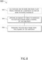
- FIG. 8 is a method or process 800 for uninstalling the seatback cover attachment system 120 from the aircraft seat 100, in accordance with one or more embodiments of the disclosure. It is noted herein “seatback cover attachment system” and variants including, but not limited to, “attachment system” or “system” may be considered equivalent, for purposes of the disclosure.
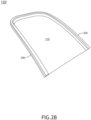
- the integrated cover and cushion sub-system 208 includes a dress cover 210. It is noted herein the dress cover 210 may conform to a portion of a user (e.g., a passenger, a crew member, or the like), or may be independently-shaped.
- the dress cover 210 includes a seatback cover layer 212.
- the seatback cover layer 212 may be formed of any material known in the art including, but not limited to, leather, synthetic leather, fabric, or the like.
- the dress cover 210 includes a seatback cushion layer 214.
- the seatback cushion layer 214 may be formed of any material known in the art including, but not limited to, foam, or the like.
- the seatback cushion layer 214 is integrated with the seatback cover layer 212 of the dress cover 210.
- the dress cover 210 may be formed of a laminated piece of material integrated with a cushion backing (e.g., a foam backed fabric).
- the seatback cushion layer 214 may be integrated with the seatback cover layer 212 via any fabrication process (e.g., sewing, or the like) or fastening mechanism (e.g., an adhesive, or the like).
- the seatback cover attachment system 120 includes an integrated seatback cover and cushion assembly to eliminate the need for an additional seatback cushion component, thereby reducing the assembly time by reducing the number of seatback component parts.
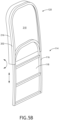
- the integrated cover and cushion sub-system 208 includes a side panel 216 formed of a piece of wrapped fabric 218.
- the side panel 216 is coupled to one or more portions of the dress cover 210 via one or more seams 219 generated via one or more sewing processes.
- the side panel 216 is joined to a portion of the substrate 202 via one or more seams 219.
- a first end of the side panel 216 may be sewn directly onto a surface 204 of the substrate 202 via a first seam 219a. It is noted that this single seam coupling mechanism may be configured to allow for efficient assembly to reduce assembly time.
- FIGS. 3A-3B depict the side panel 216 coupled to the top surface of the substrate 202
- the side panel 216 may be coupled to any surface of the substrate 202.
- the side panel 216 may be coupled to a side surface of the substrate 202.
- the side panel 216 may be coupled to a bottom surface of the substrate 202.
- the attachment system 120 may be formed of three parts (e.g., substrate 202, dress cover 210, and side panel 216), where the three parts may be coupled together to form the attachment system 120.
- the attachment system 120 may include one or more seams joining the three parts.
- the attachment system 120 may include a first seam 219a joining the dress cover 210 and the side panel 216.
- the attachment system 120 may include a second seam 219b joining the side panel 216 and the substrate 202. It is noted herein, however, the attachment system 120 may include any number of seams 219. Therefore, the above description should not be interpreted as a limitation on the present disclosure but merely an illustration.
- the substrate 202 includes a contoured surface including a lowered portion 300 and a raised portion 302 on a surface 204 of the substrate 202.
- the fabric 218 of the dress cover 210 may be configured to attached to the lowered portion 300 via one or more attachment mechanisms (e.g., one or more seams 219, or the like) generated by one or more fabrication processes (e.g., one or more sewing processes, or the like).
- the raised portion 302 is dimensioned to obscure the one or more seams 219 from a rear view of the aircraft seat 100. To this end, the height of the raised portion 302 is greater than or equal to the thickness of the fabric 218 of the side panel 216 to obscure the seam 219.
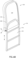
- the attachment system 120 may include one or more side panel flaps 402 configured to visually hide the one or more seatback frame mounts and the one or more seatback frame cut outs 400.
- the one or more side panel flaps 402 may be coupled to the substrate 202 via one or more fastening assemblies 404.
- the one or more side panel flaps 402 may include a snap 406 and the substrate 202 may include a receiving snap 408.
- the one or more side panel flaps 402 may be coupled to the substrate 202 by fastening the snap 406 to the receiving snap 408.
- the one or more side panel flaps 402 may include a hook and loop fastening assembly including a loop portion coupled to the flap 402 and a hook portion coupled to the substrate 202.
- the one or more side panel flaps 402 may be coupled to the substrate 202 by fastening the hook portion of the substrate 202 to the loop portion of the flap 402.
- Installing an aircraft seatback using the seatback cover attachment system 120 may include one or more of the following steps of the method or process 700:
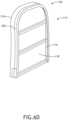
- the seatback frame 114 may be inserted into a portion of the attachment system 120.
- a portion of the one or more seatback frame elements 116 may be inserted at an angle 502 into the channel 206 of the substrate 202.
- a force may be applied to engage the seatback frame 114 with the channel 206 until the attachment system 120 interlocks with the seatback frame 114.
- the force may be applied through an application of force on the attachment system 120 in a specific direction until the attachment system 120 interlocks with the seatback frame 114.
- the force may be applied in a downward direction from the channel 206 of the substrate 202.
- the force may be applied to engage the seatback frame 114 with the channel 206 until the substrate 202 snaps into place.
- the attachment system 120 when the attachment system 120 engages with the seatback frame 114, the attachment system 120 may be configured to prevent the diaphragm 118 from cutting into the side panel 216.
- the substrate 202 may be coupled to the side panel 216 such that a portion of the substrate 202 overlaps with a portion of the side panel 216.
- the substrate 202 of the overlap is configured to prevent the diaphragm 118 from cutting into the side panel.
- the attachment system 120 may be easily installed without removing the diaphragm 118 and/or damaging the diaphragm 118.
- the attachment system 120 may interlock with the seatback frame 114 when a specific amount of force is applied.
- the force may cause the substrate 202 to flex into place to cause the attachment system 120 to interlock with the seatback frame 114.
- the attachment system 120 does not require an additional interlocking assembly to secure the attachment system 120 with seatback frame 114.
- one or more side panel flaps may be coupled to a portion of the substrate 202 via one or more fastening assemblies.
- the attachment system 120 may include one or more side panel flaps 402 configured to visually hide the one or more seatback frame mounts and the one or more seatback frame cut outs 400.
- the one or more side panel flaps 402 may be coupled to the substrate 202 via one or more fastening assemblies 404.
- the one or more side panel flaps 402 may include a snap 406 and the substrate 202 may include a receiving snap 408.
- the one or more side panel flaps 402 may be coupled to the substrate 202 by fastening the snap 406 to the receiving snap 408.
- one or more side panel flaps may be un-coupled from a portion of the substrate 202 via one or more fastening assemblies.
- the attachment system 120 may include one or more side panel flaps 402 configured to visually hide the one or more seatback frame mounts and the one or more seatback frame cut outs 400.
- the one or more side panel flaps 402 may be coupled to the substrate 202 via one or more fastening assemblies 404 when assembling the seat 100.
- the one or more side panel flaps 402 may then be un-coupled from the substrate 202 via the one or more fastening assemblies 404 when disassembling the seat 100.
- the one or more side panel flaps 402 may include a snap 406 and the substrate 202 may include a receiving snap 408.
- the one or more side panel flaps 402 may be coupled to the substrate 202 by fastening the snap 406 to the receiving snap 408 and later un-coupled via the snap 406 and receiving snap 408.
- the one or more side panel flaps 402 may include a hook and loop fastening assembly including a loop portion coupled to the flap 402 and a hook portion coupled to the substrate 202 and then later un-coupled via the hook and loop fastening assembly.
Landscapes
- Engineering & Computer Science (AREA)
- Aviation & Aerospace Engineering (AREA)
- Transportation (AREA)
- Mechanical Engineering (AREA)
- Seats For Vehicles (AREA)
Claims (10)
- Sitzrückenlehnenbezug-Befestigungssystem (120), umfassend:ein Substrat (202), wobei das Substrat dazu konfiguriert ist, reversibel mit einem Abschnitt eines Sitzrückenlehnenrahmens (114) gekoppelt zu werden, wobei das Substrat eine oder mehrere Flächen (204) beinhaltet, die einen Kanal (206) definieren, wobei der Kanal dazu konfiguriert ist, einen Abschnitt des Sitzrückenlehnenrahmens aufzunehmen; undein Sitzrückenlehnenbezug-Teilsystem (208), wobei das Sitzrückenlehnenbezug-Teilsystem Folgendes umfasst:einen Abdeckbezug (210); undeine Seitenplatte (216), wobei die Seitenplatte dazu konfiguriert ist, mit einem Abschnitt des Substrats verbunden zu werden, wobei die Seitenplatte dazu konfiguriert ist, mit einem oder mehreren Abschnitten des Abdeckbezugs verbunden zu werden, um das Sitzrückenlehnenbezug-Teilsystem zu bilden; und dadurch gekennzeichnet, dass der Abdeckbezug eine Sitzrückenlehnenbezugschicht (212) und eine Sitzrückenlehnenpolsterschicht (214) beinhaltet, wobei die Sitzrückenlehnenpolsterschicht mit der Sitzrückenlehnenbezugschicht integriert ist; und wobei:
die Seitenplatte (216) aus einem Stück gewickeltem Stoff (218) gebildet ist, der durch eine oder mehrere Nähte (219) direkt mit einem Abschnitt des Substrats verbunden ist und durch eine oder mehrere Nähte mit einem Abschnitt des Abdeckbezugs verbunden ist; und wobei das Substrat eine konturierte Fläche beinhaltet, die einen abgesenkten Abschnitt (300) und einen erhöhten Abschnitt (302) auf einer Fläche (204) des Substrats beinhaltet, und die Höhe des erhöhten Abschnitts (302) größer oder gleich der Dicke des Stoffes (218) der Seitenplatte ist, um die eine oder mehreren Nähte bei einer Rückansicht eines Sitzes, an dem das Substrat befestigt ist, zu verdecken. - Sitzrückenlehnenbezug-Befestigungssystem nach Anspruch 1, wobei das Substrat einen oder mehrere Sitzrückenlehnenrahmen-Halterungsausschnitte (400) beinhaltet, die dazu konfiguriert sind, sich an eine oder mehrere Sitzrückenlehnenrahmen-Halterungen des Sitzrückenlehnenrahmens anzupassen.
- Sitzrückenlehnenbezug-Befestigungssystem nach Anspruch 2, ferner umfassend:
eine oder mehrere Klappen (402), die eine oder mehrere Befestigungsbraugruppen (404) beinhalten, die dazu konfiguriert sind, die eine oder mehreren Sitzrückenlehnenrahmen-Halterungen optisch zu verbergen. - Sitzrückenlehnenbezug-Befestigungssystem nach einem der vorhergehenden Ansprüche, wobei das Substrat aus einem thermogeformtem Kunststoff oder laminiertem Fiberglas gebildet ist.
- Flugzeugsitz, umfassend:ein Stützsystem (102), das einen Sitzrückenlehnenrahmen (114) und einen Sitzflächenrahmen (106) beinhaltet;einen Sitzflächenbezug (112), der mindestens eine Fläche beinhaltet, die dazu konfiguriert ist, sich an eine entsprechende Fläche des Stützsystems anzupassen; undein Sitzrückenlehnenbezug-Befestigungssystem (120) nach einem der vorhergehenden Ansprüche,das Sitzrückenlehnenbezug-Befestigungssystem, das dazu konfiguriert ist, das Sitzrückenlehnenbezug-Teilsystem über das Substrat an dem Sitzrückenlehnenrahmen anzubringen.
- Flugzeugsitz nach Anspruch 5, wobei der Sitzrückenlehnenrahmen dazu konfiguriert ist, in den Kanal des Sitzrückenlehnenbezug-Befestigungssystems zu passen.
- Flugzeugsitz nach Anspruch 6, wobei der Sitzrückenlehnenrahmen dazu konfiguriert ist, in den Kanal des Sitzrückenlehnenbezug-Befestigungssystems eingesetzt zu werden.
- Flugzeugsitz nach Anspruch 5, wobei der Sitzrückenlehnenrahmen dazu konfiguriert ist, über eine Kraft, die von dem Kanal des Sitzrückenlehnenbezug-Befestigungssystems nach unten ausgeübt wird, in das Substrat einzugreifen.
- Flugzeugsitz nach Anspruch 5, wobei der Sitzrückenlehnenrahmen dazu konfiguriert ist, über eine Kraft, die von dem Kanal des Sitzrückenlehnenbezug-Befestigungssystems nach oben ausgeübt wird, sich von dem Substrat zu lösen.
- Flugzeugsitz nach Anspruch 5, wobei sich das Substrat und die Seitenplatte mindestens teilweise überlappen, um zu verhindern, dass eine Sitzrückenlehnenmembran des Sitzrückenlehnenrahmens in einen Abschnitt der Seitenplatte einschneidet.
Applications Claiming Priority (1)
| Application Number | Priority Date | Filing Date | Title |
|---|---|---|---|
| US17/308,789 US11396377B1 (en) | 2021-05-05 | 2021-05-05 | Aircraft seatback cover attachment system |
Publications (2)
| Publication Number | Publication Date |
|---|---|
| EP4086114A1 EP4086114A1 (de) | 2022-11-09 |
| EP4086114B1 true EP4086114B1 (de) | 2025-04-09 |
Family
ID=81585177
Family Applications (1)
| Application Number | Title | Priority Date | Filing Date |
|---|---|---|---|
| EP22171843.0A Active EP4086114B1 (de) | 2021-05-05 | 2022-05-05 | Flugzeugsitzrückenlehnenbezug-befestigungssystem |
Country Status (2)
| Country | Link |
|---|---|
| US (1) | US11396377B1 (de) |
| EP (1) | EP4086114B1 (de) |
Families Citing this family (6)
| Publication number | Priority date | Publication date | Assignee | Title |
|---|---|---|---|---|
| US12221215B2 (en) * | 2020-05-29 | 2025-02-11 | B/E Aerospace, Inc. | Seat divider sail |
| EP4434886B1 (de) | 2023-03-21 | 2025-06-04 | B/E Aerospace, Inc. | In form eines formgedächtnispolymers integrierte polsterpolsterung mit künstlicher muskeltechnologie |
| US12434844B2 (en) | 2023-03-21 | 2025-10-07 | B/E Aerospace, Inc. | Shape memory polymer integrated cushion upholstery using artificial muscles technology |
| US12459650B2 (en) * | 2023-06-23 | 2025-11-04 | B/E Aerospace, Inc. | Converting economy seat to full flat bed by dropping seat back frame |
| EP4512719A1 (de) | 2023-08-22 | 2025-02-26 | Dehns | Ausziehbare sitzfläche |
| US12570403B2 (en) | 2023-08-22 | 2026-03-10 | B/E Aerospace, Inc. | Intelligent deployment control of break over seat pan using textile pressure mapping technique |
Family Cites Families (30)
| Publication number | Priority date | Publication date | Assignee | Title |
|---|---|---|---|---|
| US4740034A (en) * | 1987-03-09 | 1988-04-26 | Snyder William F | Protective stool bumper |
| US5826939A (en) * | 1997-08-13 | 1998-10-27 | Lear Corporation | Method and apparatus for attaching a trim cover to a seat frame |
| IT236358Y1 (it) | 1997-11-28 | 2000-08-08 | Bruzolo Manifatt Gestind Mb | Appoggiatesta per sedili di autoveicoli. |
| JP4318384B2 (ja) * | 2000-05-31 | 2009-08-19 | テイ・エス テック株式会社 | 車両用シート |
| FR2820399B1 (fr) * | 2001-02-05 | 2003-08-01 | Sicma Aero Seat | Structure de dossier pour siege d'avion avec toile de recouvrement et procede de montage de la structure |
| DE10120118B4 (de) | 2001-04-25 | 2005-04-07 | Franz Kiel Gmbh & Co. Kg | Fahrgastsitz |
| ITPN20010072A1 (it) | 2001-10-16 | 2003-04-16 | Leonardo Snc | Elemento per il posizionamento e fissaggio della foderina di rivestimento di sedili e di veicoli |
| KR20020039293A (ko) | 2002-04-22 | 2002-05-25 | 부강테크 주식회사 | 시트 카바의 체결구 |
| GB2459254A (en) | 2008-04-10 | 2009-10-21 | Auto Kit Internat Ltd | Seat cover with retaining formation |
| FR2935314B1 (fr) * | 2008-09-03 | 2011-12-09 | Faurecia Sieges Automobile | Element de siege de vehicule, siege de vehicule comprenant un tel element de siege et procede de realisation d'un tel element de siege. |
| US7857383B2 (en) * | 2008-12-11 | 2010-12-28 | Ykk Corporation | Soft cover for covering a seat |
| JP5387956B2 (ja) | 2009-03-31 | 2014-01-15 | テイ・エス テック株式会社 | トリムカバーの端末止着構造 |
| ITMN20090021A1 (it) | 2009-10-02 | 2011-04-03 | Austo S R L | Coprisedili per veicoli: |
| FR2977541B1 (fr) * | 2011-07-04 | 2014-01-24 | Peugeot Citroen Automobiles Sa | Dispositif de fixation d'une coiffe de garnissage de siege automobile sur l'armature de siege |
| JP5768591B2 (ja) * | 2011-08-23 | 2015-08-26 | トヨタ紡織株式会社 | 車両用シート |
| JP5876255B2 (ja) * | 2011-09-08 | 2016-03-02 | 株式会社イレブンインターナショナル | シートカバー及びカバー取付具 |
| US11014675B2 (en) * | 2014-04-03 | 2021-05-25 | Franklin Products, Inc. | Lightweight upholstery cover with edge attachment |
| US11097640B2 (en) | 2014-04-03 | 2021-08-24 | Franklin Products, Inc. | Method and articles for attaching upholstery covers and other flexible material |
| CN107207094B (zh) * | 2014-12-31 | 2019-08-23 | 新科宇航 | 座椅悬架安装方法和乘客座椅 |
| JP6433022B2 (ja) * | 2015-02-23 | 2018-12-05 | 株式会社タチエス | 車両用シートの表皮固定構造、車両用シートの操作レバー装置及び車両用シート |
| US11110835B2 (en) | 2016-11-21 | 2021-09-07 | Thomas Pierce | Hygienic headrest cover and kit |
| GB2548906B (en) * | 2016-04-01 | 2020-08-12 | Mirus Aircraft Seating Ltd | Seat back for vehicle |
| US11530044B2 (en) * | 2016-09-20 | 2022-12-20 | Safran Seats Usa Llc | Using foam for structural components of a seat assembly |
| EP3519245B1 (de) | 2016-09-27 | 2021-07-28 | Proma S.p.A. | Sitz für fahrzeuge mit einer einrastkante |
| GB201702823D0 (en) | 2017-02-22 | 2017-04-05 | Acro Aircraft Seating Ltd | Seat part comprising a seat cover |
| WO2019017834A1 (en) | 2017-07-19 | 2019-01-24 | ST Engineering Aerospace Ltd. | DOSSIER FOR A PASSENGER SEAT |
| US10442329B2 (en) * | 2017-11-09 | 2019-10-15 | B/E Aerospace Fischer Gmbh | Clip and method for attaching and tensioning seat dress covers |
| GB2580026B (en) * | 2018-12-19 | 2023-02-22 | Safran Seats Gb Ltd | Aircraft seat |
| DE102020106684A1 (de) * | 2019-04-26 | 2020-10-29 | Adient Engineering and IP GmbH | Halterung zum Halten einer Verkleidung an einer Sitzstruktur und Sitzbraugruppe mit einer Sitzstruktur und einer solchen Halterung |
| US11492124B2 (en) * | 2020-03-20 | 2022-11-08 | B/E Aerospace, Inc. | Dress cover drawstring retention system |
-
2021
- 2021-05-05 US US17/308,789 patent/US11396377B1/en active Active
-
2022
- 2022-05-05 EP EP22171843.0A patent/EP4086114B1/de active Active
Also Published As
| Publication number | Publication date |
|---|---|
| EP4086114A1 (de) | 2022-11-09 |
| US11396377B1 (en) | 2022-07-26 |
Similar Documents
| Publication | Publication Date | Title |
|---|---|---|
| EP4086114B1 (de) | Flugzeugsitzrückenlehnenbezug-befestigungssystem | |
| EP3960628B1 (de) | System zur befestigung von flugzeugsitzbezügen | |
| US10231563B2 (en) | Integrated curtain system and method | |
| EP3816049B1 (de) | Einfassungsmontierte trennung für sitzprivatsphäre | |
| EP2743181B1 (de) | Trennvorhang | |
| EP3078592B1 (de) | Überkopf-gepäckablagebaugruppe für ein fahrzeug | |
| EP4056473A1 (de) | Komprimierbares kissen für einen flugzeugsitz | |
| EP3365229B1 (de) | Klassenteiler für eine flugzeugpassagierkabine | |
| EP3578456B1 (de) | Puckabdeckung | |
| EP4108566A1 (de) | Wagenanordnung mit überlastungsschutz | |
| EP4455009A1 (de) | Passagiersitzsystem | |
| EP4116194A1 (de) | Passagiersitze, die in der nähe einer flugzeuginnenstruktur positioniert sind | |
| EP3960038B1 (de) | Befestigungsanordnung für bezug und polster eines flugzeugsitzes | |
| EP4122828B1 (de) | Modulares flugzeugsitzrückenlehnenabdeckung-befestigungssystem | |
| EP4194261B1 (de) | Flugzeugsitzbasisanordnung | |
| EP4056416B1 (de) | Anzugsabdeckung für ausziehbare kissen | |
| US12122520B2 (en) | Spring-based seat diaphragm | |
| US11034454B1 (en) | Seat spreader mounted seat privacy closeout | |
| US20230065564A1 (en) | Lift assist system for an aircraft seat | |
| US11572001B1 (en) | Quick release headrest removal assembly |
Legal Events
| Date | Code | Title | Description |
|---|---|---|---|
| PUAI | Public reference made under article 153(3) epc to a published international application that has entered the european phase |
Free format text: ORIGINAL CODE: 0009012 |
|
| STAA | Information on the status of an ep patent application or granted ep patent |
Free format text: STATUS: THE APPLICATION HAS BEEN PUBLISHED |
|
| AK | Designated contracting states |
Kind code of ref document: A1 Designated state(s): AL AT BE BG CH CY CZ DE DK EE ES FI FR GB GR HR HU IE IS IT LI LT LU LV MC MK MT NL NO PL PT RO RS SE SI SK SM TR |
|
| STAA | Information on the status of an ep patent application or granted ep patent |
Free format text: STATUS: REQUEST FOR EXAMINATION WAS MADE |
|
| 17P | Request for examination filed |
Effective date: 20230509 |
|
| RBV | Designated contracting states (corrected) |
Designated state(s): AL AT BE BG CH CY CZ DE DK EE ES FI FR GB GR HR HU IE IS IT LI LT LU LV MC MK MT NL NO PL PT RO RS SE SI SK SM TR |
|
| P01 | Opt-out of the competence of the unified patent court (upc) registered |
Effective date: 20230922 |
|
| STAA | Information on the status of an ep patent application or granted ep patent |
Free format text: STATUS: EXAMINATION IS IN PROGRESS |
|
| 17Q | First examination report despatched |
Effective date: 20240605 |
|
| GRAP | Despatch of communication of intention to grant a patent |
Free format text: ORIGINAL CODE: EPIDOSNIGR1 |
|
| STAA | Information on the status of an ep patent application or granted ep patent |
Free format text: STATUS: GRANT OF PATENT IS INTENDED |
|
| INTG | Intention to grant announced |
Effective date: 20241114 |
|
| GRAS | Grant fee paid |
Free format text: ORIGINAL CODE: EPIDOSNIGR3 |
|
| GRAA | (expected) grant |
Free format text: ORIGINAL CODE: 0009210 |
|
| STAA | Information on the status of an ep patent application or granted ep patent |
Free format text: STATUS: THE PATENT HAS BEEN GRANTED |
|
| AK | Designated contracting states |
Kind code of ref document: B1 Designated state(s): AL AT BE BG CH CY CZ DE DK EE ES FI FR GB GR HR HU IE IS IT LI LT LU LV MC MK MT NL NO PL PT RO RS SE SI SK SM TR |
|
| REG | Reference to a national code |
Ref country code: GB Ref legal event code: FG4D |
|
| REG | Reference to a national code |
Ref country code: CH Ref legal event code: EP |
|
| REG | Reference to a national code |
Ref country code: DE Ref legal event code: R096 Ref document number: 602022012779 Country of ref document: DE |
|
| REG | Reference to a national code |
Ref country code: IE Ref legal event code: FG4D |
|
| PGFP | Annual fee paid to national office [announced via postgrant information from national office to epo] |
Ref country code: DE Payment date: 20250423 Year of fee payment: 4 |
|
| PGFP | Annual fee paid to national office [announced via postgrant information from national office to epo] |
Ref country code: FR Payment date: 20250520 Year of fee payment: 4 |
|
| PGFP | Annual fee paid to national office [announced via postgrant information from national office to epo] |
Ref country code: AT Payment date: 20250721 Year of fee payment: 4 |
|
| REG | Reference to a national code |
Ref country code: NL Ref legal event code: MP Effective date: 20250409 |
|
| PG25 | Lapsed in a contracting state [announced via postgrant information from national office to epo] |
Ref country code: NL Free format text: LAPSE BECAUSE OF FAILURE TO SUBMIT A TRANSLATION OF THE DESCRIPTION OR TO PAY THE FEE WITHIN THE PRESCRIBED TIME-LIMIT Effective date: 20250409 |
|
| REG | Reference to a national code |
Ref country code: AT Ref legal event code: MK05 Ref document number: 1783263 Country of ref document: AT Kind code of ref document: T Effective date: 20250409 |
|
| PG25 | Lapsed in a contracting state [announced via postgrant information from national office to epo] |
Ref country code: FI Free format text: LAPSE BECAUSE OF FAILURE TO SUBMIT A TRANSLATION OF THE DESCRIPTION OR TO PAY THE FEE WITHIN THE PRESCRIBED TIME-LIMIT Effective date: 20250409 Ref country code: ES Free format text: LAPSE BECAUSE OF FAILURE TO SUBMIT A TRANSLATION OF THE DESCRIPTION OR TO PAY THE FEE WITHIN THE PRESCRIBED TIME-LIMIT Effective date: 20250409 Ref country code: PT Free format text: LAPSE BECAUSE OF FAILURE TO SUBMIT A TRANSLATION OF THE DESCRIPTION OR TO PAY THE FEE WITHIN THE PRESCRIBED TIME-LIMIT Effective date: 20250811 |
|
| REG | Reference to a national code |
Ref country code: LT Ref legal event code: MG9D |
|
| PG25 | Lapsed in a contracting state [announced via postgrant information from national office to epo] |
Ref country code: GR Free format text: LAPSE BECAUSE OF FAILURE TO SUBMIT A TRANSLATION OF THE DESCRIPTION OR TO PAY THE FEE WITHIN THE PRESCRIBED TIME-LIMIT Effective date: 20250710 Ref country code: NO Free format text: LAPSE BECAUSE OF FAILURE TO SUBMIT A TRANSLATION OF THE DESCRIPTION OR TO PAY THE FEE WITHIN THE PRESCRIBED TIME-LIMIT Effective date: 20250709 |
|
| PG25 | Lapsed in a contracting state [announced via postgrant information from national office to epo] |
Ref country code: PL Free format text: LAPSE BECAUSE OF FAILURE TO SUBMIT A TRANSLATION OF THE DESCRIPTION OR TO PAY THE FEE WITHIN THE PRESCRIBED TIME-LIMIT Effective date: 20250409 |
|
| PG25 | Lapsed in a contracting state [announced via postgrant information from national office to epo] |
Ref country code: BG Free format text: LAPSE BECAUSE OF FAILURE TO SUBMIT A TRANSLATION OF THE DESCRIPTION OR TO PAY THE FEE WITHIN THE PRESCRIBED TIME-LIMIT Effective date: 20250409 |
|
| PG25 | Lapsed in a contracting state [announced via postgrant information from national office to epo] |
Ref country code: AT Free format text: LAPSE BECAUSE OF FAILURE TO SUBMIT A TRANSLATION OF THE DESCRIPTION OR TO PAY THE FEE WITHIN THE PRESCRIBED TIME-LIMIT Effective date: 20250409 Ref country code: HR Free format text: LAPSE BECAUSE OF FAILURE TO SUBMIT A TRANSLATION OF THE DESCRIPTION OR TO PAY THE FEE WITHIN THE PRESCRIBED TIME-LIMIT Effective date: 20250409 |
|
| PG25 | Lapsed in a contracting state [announced via postgrant information from national office to epo] |
Ref country code: RS Free format text: LAPSE BECAUSE OF FAILURE TO SUBMIT A TRANSLATION OF THE DESCRIPTION OR TO PAY THE FEE WITHIN THE PRESCRIBED TIME-LIMIT Effective date: 20250709 |
|
| PG25 | Lapsed in a contracting state [announced via postgrant information from national office to epo] |
Ref country code: IS Free format text: LAPSE BECAUSE OF FAILURE TO SUBMIT A TRANSLATION OF THE DESCRIPTION OR TO PAY THE FEE WITHIN THE PRESCRIBED TIME-LIMIT Effective date: 20250809 |
|
| PG25 | Lapsed in a contracting state [announced via postgrant information from national office to epo] |
Ref country code: LV Free format text: LAPSE BECAUSE OF FAILURE TO SUBMIT A TRANSLATION OF THE DESCRIPTION OR TO PAY THE FEE WITHIN THE PRESCRIBED TIME-LIMIT Effective date: 20250409 |
|
| REG | Reference to a national code |
Ref country code: CH Ref legal event code: H13 Free format text: ST27 STATUS EVENT CODE: U-0-0-H10-H13 (AS PROVIDED BY THE NATIONAL OFFICE) Effective date: 20251223 |
|
| REG | Reference to a national code |
Ref country code: DE Ref legal event code: R097 Ref document number: 602022012779 Country of ref document: DE |
|
| PG25 | Lapsed in a contracting state [announced via postgrant information from national office to epo] |
Ref country code: DK Free format text: LAPSE BECAUSE OF FAILURE TO SUBMIT A TRANSLATION OF THE DESCRIPTION OR TO PAY THE FEE WITHIN THE PRESCRIBED TIME-LIMIT Effective date: 20250409 Ref country code: SM Free format text: LAPSE BECAUSE OF FAILURE TO SUBMIT A TRANSLATION OF THE DESCRIPTION OR TO PAY THE FEE WITHIN THE PRESCRIBED TIME-LIMIT Effective date: 20250409 |
|
| PG25 | Lapsed in a contracting state [announced via postgrant information from national office to epo] |
Ref country code: LU Free format text: LAPSE BECAUSE OF NON-PAYMENT OF DUE FEES Effective date: 20250505 |
|
| PG25 | Lapsed in a contracting state [announced via postgrant information from national office to epo] |
Ref country code: CH Free format text: LAPSE BECAUSE OF NON-PAYMENT OF DUE FEES Effective date: 20250531 |
|
| PG25 | Lapsed in a contracting state [announced via postgrant information from national office to epo] |
Ref country code: CZ Free format text: LAPSE BECAUSE OF FAILURE TO SUBMIT A TRANSLATION OF THE DESCRIPTION OR TO PAY THE FEE WITHIN THE PRESCRIBED TIME-LIMIT Effective date: 20250409 |
|
| PG25 | Lapsed in a contracting state [announced via postgrant information from national office to epo] |
Ref country code: EE Free format text: LAPSE BECAUSE OF FAILURE TO SUBMIT A TRANSLATION OF THE DESCRIPTION OR TO PAY THE FEE WITHIN THE PRESCRIBED TIME-LIMIT Effective date: 20250409 |
|
| PG25 | Lapsed in a contracting state [announced via postgrant information from national office to epo] |
Ref country code: SK Free format text: LAPSE BECAUSE OF FAILURE TO SUBMIT A TRANSLATION OF THE DESCRIPTION OR TO PAY THE FEE WITHIN THE PRESCRIBED TIME-LIMIT Effective date: 20250409 |
|
| PG25 | Lapsed in a contracting state [announced via postgrant information from national office to epo] |
Ref country code: IT Free format text: LAPSE BECAUSE OF FAILURE TO SUBMIT A TRANSLATION OF THE DESCRIPTION OR TO PAY THE FEE WITHIN THE PRESCRIBED TIME-LIMIT Effective date: 20250409 |
|
| REG | Reference to a national code |
Ref country code: BE Ref legal event code: MM Effective date: 20250531 |
|
| PG25 | Lapsed in a contracting state [announced via postgrant information from national office to epo] |
Ref country code: MC Free format text: LAPSE BECAUSE OF FAILURE TO SUBMIT A TRANSLATION OF THE DESCRIPTION OR TO PAY THE FEE WITHIN THE PRESCRIBED TIME-LIMIT Effective date: 20250409 |
|
| PG25 | Lapsed in a contracting state [announced via postgrant information from national office to epo] |
Ref country code: RO Free format text: LAPSE BECAUSE OF FAILURE TO SUBMIT A TRANSLATION OF THE DESCRIPTION OR TO PAY THE FEE WITHIN THE PRESCRIBED TIME-LIMIT Effective date: 20250409 |
|
| PLBE | No opposition filed within time limit |
Free format text: ORIGINAL CODE: 0009261 |
|
| STAA | Information on the status of an ep patent application or granted ep patent |
Free format text: STATUS: NO OPPOSITION FILED WITHIN TIME LIMIT |
|
| REG | Reference to a national code |
Ref country code: CH Ref legal event code: L10 Free format text: ST27 STATUS EVENT CODE: U-0-0-L10-L00 (AS PROVIDED BY THE NATIONAL OFFICE) Effective date: 20260218 |
|
| 26N | No opposition filed |
Effective date: 20260112 |