EP4085197B1 - Leckdetektion für membranpumpen - Google Patents
Leckdetektion für membranpumpen Download PDFInfo
- Publication number
- EP4085197B1 EP4085197B1 EP20910896.8A EP20910896A EP4085197B1 EP 4085197 B1 EP4085197 B1 EP 4085197B1 EP 20910896 A EP20910896 A EP 20910896A EP 4085197 B1 EP4085197 B1 EP 4085197B1
- Authority
- EP
- European Patent Office
- Prior art keywords
- liquid
- leak detection
- detection device
- airflow
- diaphragm pump
- Prior art date
- Legal status (The legal status is an assumption and is not a legal conclusion. Google has not performed a legal analysis and makes no representation as to the accuracy of the status listed.)
- Active
Links
Images



Classifications
-
- F—MECHANICAL ENGINEERING; LIGHTING; HEATING; WEAPONS; BLASTING
- F16—ENGINEERING ELEMENTS AND UNITS; GENERAL MEASURES FOR PRODUCING AND MAINTAINING EFFECTIVE FUNCTIONING OF MACHINES OR INSTALLATIONS; THERMAL INSULATION IN GENERAL
- F16K—VALVES; TAPS; COCKS; ACTUATING-FLOATS; DEVICES FOR VENTING OR AERATING
- F16K37/00—Special means in or on valves or other cut-off apparatus for indicating or recording operation thereof, or for enabling an alarm to be given
- F16K37/0075—For recording or indicating the functioning of a valve in combination with test equipment
- F16K37/0083—For recording or indicating the functioning of a valve in combination with test equipment by measuring valve parameters
-
- F—MECHANICAL ENGINEERING; LIGHTING; HEATING; WEAPONS; BLASTING
- F04—POSITIVE - DISPLACEMENT MACHINES FOR LIQUIDS; PUMPS FOR LIQUIDS OR ELASTIC FLUIDS
- F04B—POSITIVE-DISPLACEMENT MACHINES FOR LIQUIDS; PUMPS
- F04B43/00—Machines, pumps, or pumping installations having flexible working members
- F04B43/0009—Special features
- F04B43/0081—Special features systems, control, safety measures
-
- F—MECHANICAL ENGINEERING; LIGHTING; HEATING; WEAPONS; BLASTING
- F04—POSITIVE - DISPLACEMENT MACHINES FOR LIQUIDS; PUMPS FOR LIQUIDS OR ELASTIC FLUIDS
- F04B—POSITIVE-DISPLACEMENT MACHINES FOR LIQUIDS; PUMPS
- F04B43/00—Machines, pumps, or pumping installations having flexible working members
- F04B43/0009—Special features
- F04B43/0081—Special features systems, control, safety measures
- F04B43/009—Special features systems, control, safety measures leakage control; pump systems with two flexible members; between the actuating element and the pumped fluid
-
- F—MECHANICAL ENGINEERING; LIGHTING; HEATING; WEAPONS; BLASTING
- F04—POSITIVE - DISPLACEMENT MACHINES FOR LIQUIDS; PUMPS FOR LIQUIDS OR ELASTIC FLUIDS
- F04B—POSITIVE-DISPLACEMENT MACHINES FOR LIQUIDS; PUMPS
- F04B43/00—Machines, pumps, or pumping installations having flexible working members
- F04B43/02—Machines, pumps, or pumping installations having flexible working members having plate-like flexible members, e.g. diaphragms
-
- F—MECHANICAL ENGINEERING; LIGHTING; HEATING; WEAPONS; BLASTING
- F04—POSITIVE - DISPLACEMENT MACHINES FOR LIQUIDS; PUMPS FOR LIQUIDS OR ELASTIC FLUIDS
- F04B—POSITIVE-DISPLACEMENT MACHINES FOR LIQUIDS; PUMPS
- F04B43/00—Machines, pumps, or pumping installations having flexible working members
- F04B43/02—Machines, pumps, or pumping installations having flexible working members having plate-like flexible members, e.g. diaphragms
- F04B43/06—Pumps having fluid drive
-
- F—MECHANICAL ENGINEERING; LIGHTING; HEATING; WEAPONS; BLASTING
- F04—POSITIVE - DISPLACEMENT MACHINES FOR LIQUIDS; PUMPS FOR LIQUIDS OR ELASTIC FLUIDS
- F04B—POSITIVE-DISPLACEMENT MACHINES FOR LIQUIDS; PUMPS
- F04B49/00—Control, e.g. of pump delivery, or pump pressure of, or safety measures for, machines, pumps, or pumping installations, not otherwise provided for, or of interest apart from, groups F04B1/00 - F04B47/00
- F04B49/10—Other safety measures
-
- F—MECHANICAL ENGINEERING; LIGHTING; HEATING; WEAPONS; BLASTING
- F04—POSITIVE - DISPLACEMENT MACHINES FOR LIQUIDS; PUMPS FOR LIQUIDS OR ELASTIC FLUIDS
- F04B—POSITIVE-DISPLACEMENT MACHINES FOR LIQUIDS; PUMPS
- F04B51/00—Testing machines, pumps, or pumping installations
-
- F—MECHANICAL ENGINEERING; LIGHTING; HEATING; WEAPONS; BLASTING
- F16—ENGINEERING ELEMENTS AND UNITS; GENERAL MEASURES FOR PRODUCING AND MAINTAINING EFFECTIVE FUNCTIONING OF MACHINES OR INSTALLATIONS; THERMAL INSULATION IN GENERAL
- F16K—VALVES; TAPS; COCKS; ACTUATING-FLOATS; DEVICES FOR VENTING OR AERATING
- F16K37/00—Special means in or on valves or other cut-off apparatus for indicating or recording operation thereof, or for enabling an alarm to be given
- F16K37/0075—For recording or indicating the functioning of a valve in combination with test equipment
- F16K37/0091—For recording or indicating the functioning of a valve in combination with test equipment by measuring fluid parameters
-
- G—PHYSICS
- G01—MEASURING; TESTING
- G01F—MEASURING VOLUME, VOLUME FLOW, MASS FLOW OR LIQUID LEVEL; METERING BY VOLUME
- G01F23/00—Indicating or measuring liquid level or level of fluent solid material, e.g. indicating in terms of volume or indicating by means of an alarm
-
- G—PHYSICS
- G01—MEASURING; TESTING
- G01F—MEASURING VOLUME, VOLUME FLOW, MASS FLOW OR LIQUID LEVEL; METERING BY VOLUME
- G01F23/00—Indicating or measuring liquid level or level of fluent solid material, e.g. indicating in terms of volume or indicating by means of an alarm
- G01F23/30—Indicating or measuring liquid level or level of fluent solid material, e.g. indicating in terms of volume or indicating by means of an alarm by floats
-
- F—MECHANICAL ENGINEERING; LIGHTING; HEATING; WEAPONS; BLASTING
- F04—POSITIVE - DISPLACEMENT MACHINES FOR LIQUIDS; PUMPS FOR LIQUIDS OR ELASTIC FLUIDS
- F04B—POSITIVE-DISPLACEMENT MACHINES FOR LIQUIDS; PUMPS
- F04B2201/00—Pump parameters
- F04B2201/08—Cylinder or housing parameters
- F04B2201/0803—Leakage
-
- Y—GENERAL TAGGING OF NEW TECHNOLOGICAL DEVELOPMENTS; GENERAL TAGGING OF CROSS-SECTIONAL TECHNOLOGIES SPANNING OVER SEVERAL SECTIONS OF THE IPC; TECHNICAL SUBJECTS COVERED BY FORMER USPC CROSS-REFERENCE ART COLLECTIONS [XRACs] AND DIGESTS
- Y10—TECHNICAL SUBJECTS COVERED BY FORMER USPC
- Y10T—TECHNICAL SUBJECTS COVERED BY FORMER US CLASSIFICATION
- Y10T137/00—Fluid handling
- Y10T137/2931—Diverse fluid containing pressure systems
- Y10T137/3003—Fluid separating traps or vents
- Y10T137/3084—Discriminating outlet for gas
-
- Y—GENERAL TAGGING OF NEW TECHNOLOGICAL DEVELOPMENTS; GENERAL TAGGING OF CROSS-SECTIONAL TECHNOLOGIES SPANNING OVER SEVERAL SECTIONS OF THE IPC; TECHNICAL SUBJECTS COVERED BY FORMER USPC CROSS-REFERENCE ART COLLECTIONS [XRACs] AND DIGESTS
- Y10—TECHNICAL SUBJECTS COVERED BY FORMER USPC
- Y10T—TECHNICAL SUBJECTS COVERED BY FORMER US CLASSIFICATION
- Y10T137/00—Fluid handling
- Y10T137/5762—With leakage or drip collecting
- Y10T137/5907—Collector for waste liquid derived from solid, gas or vapor
-
- Y—GENERAL TAGGING OF NEW TECHNOLOGICAL DEVELOPMENTS; GENERAL TAGGING OF CROSS-SECTIONAL TECHNOLOGIES SPANNING OVER SEVERAL SECTIONS OF THE IPC; TECHNICAL SUBJECTS COVERED BY FORMER USPC CROSS-REFERENCE ART COLLECTIONS [XRACs] AND DIGESTS
- Y10—TECHNICAL SUBJECTS COVERED BY FORMER USPC
- Y10T—TECHNICAL SUBJECTS COVERED BY FORMER US CLASSIFICATION
- Y10T137/00—Fluid handling
- Y10T137/8158—With indicator, register, recorder, alarm or inspection means
- Y10T137/8342—Liquid level responsive indicator, recorder or alarm
Definitions
- This invention relates to pump leak detection.
- Air-operated diaphragm pumps are used for liquid transfer in many different industries. For instance, air-operated diaphragm pumps are used for liquid transfer where purity of the transfer liquid, high flow rates, and/or reliable and predictable flow volumes are needed. Air-operated diaphragm pumps are also used to transfer hazardous chemicals. For example, air-operated diaphragm pumps are commonly used in industries such as the food and beverage industry, chemical processing, oil and gas, and the semiconductor industry.
- Diaphragm ruptures or leaks diminish the performance of the pump, and may introduce impurities into the transfer liquid, or may expose personnel to a hazardous transfer liquid.
- Leak detection devices can be used to detect diaphragm leaks.
- existing leak detection devices often rely on restrictive airflow paths to remove entrained liquid from pump exhaust air and detect a leak.
- restrictive airflow paths can reduce the operating efficiency and effectiveness of an air-operated pump by, for example, creating a backpressure on the pump's exhaust. The back pressure reduces the differential pressure available across a pump's diaphragm thus reducing the pump's output pressure and/or pumping rate. Accordingly, improvements are continually sought for diaphragm leak detection.
- CN 103 147 971 A belongs to the technical field of liquid material conveying security control in a chemical industry, and provides a security controller for diaphragm leakage liquid of an air diaphragm pump.
- the security controller comprises a rotary gas-liquid separator, a mandril, a gas source control valve, a gas discharge pipe, an overflow preventing device and a liquid seal device.
- CN 103 147 971 A further provides a method for controlling the diaphragm leakage liquid of the air diaphragm pump through the security controller for the diaphragm liquid leakage of the air diaphragm pump.
- Implementations of the present disclosure are generally directed to a leak detection device. More specifically, implementations are directed to a diaphragm leak detection device for air-operated pumps and a pump system incorporating the leak detection device. Implementations of the leak detection device described herein employ a minimally restrictive path from the air exhaust of the air-operated pump, through the leak detection device, and into a pump muffler. Implementations of the leak detection device provide an air impingement surface directly in the flow path of the exhaust air from the pump. The air impingement surface causes heavy liquid particles entrained in the air (e.g., from a diaphragm leak) to fall out of the air flow when they impact the surface and it diverts the air around the surface. The liquid is collected in a liquid reservoir and a liquid level detector is used to alert personnel to the diaphragm leak.
- a liquid level detector is used to alert personnel to the diaphragm leak.
- a diaphragm pump leak detection device and a diaphragm pump leak detection method according to the present invention are set out in the independent claims. Further advantageous developments of the present invention are set out in the dependent claims.
- a surface of the liquid separator forms a direct impingement surface and the body of the diaphragm leak detection device is configured to direct airflow from the exhaust outlet against the direct impingement surface.
- the body of the diaphragm leak detection device includes an upper housing and a lower housing.
- the upper housing includes the airflow inlet and the airflow outlet.
- the lower housing defines the liquid reservoir.
- the liquid separator includes a cylinder and a sleeve.
- the cylinder is coupled to the body and positioned directly between the airflow inlet and the airflow outlet.
- the sleeve is configured to interface with a lower portion of the cylinder.
- the sleeve includes the channel, where a first end of the channel terminates at the lower portion of the cylinder and a second end of the channel opens to the liquid reservoir.
- the liquid level detector is coupled to the lower portion of the cylinder and extends into the channel.
- the body of the diaphragm leak detection device includes a shelf positioned above the liquid reservoir.
- the sleeve includes a tapered flange in contact with the shelf. The tapered flange separates the liquid reservoir from an airflow path in an upper portion of the body.
- the shelf includes at least one drain channel that provides liquid communication between the liquid reservoir and the airflow path.
- the liquid level detector comprises a float switch assembly.
- the body of the diaphragm leak detection device includes an upper housing and a lower housing.
- the upper housing includes the airflow inlet and the airflow outlet.
- the lower housing is separable from the upper housing.
- the lower housing includes the liquid reservoir, the shelf, and at least one drain channel.
- implementations of the invention provide an air-operated pump leak detection device that imposes minimal flow restriction exhaust air. Implementations may provide leak detection capabilities with little or no increase in backpressure on air-operated pump exhaust.
- FIG. 1 depicts a perspective view of an air-operated diaphragm pumping system 100.
- the system includes diaphragm pump 101, the pump's air-valve assembly 102, a muffler plate 104, a leak detection device 106, and a muffler 108.
- FIG. 2 depicts a functional diagram of an exemplary air-operated diaphragm pump 101.
- pump 101 operates by alternately applying high pressure air to one of two diaphragms 202A and 202B during a liquid discharge stroke and exhausting the air to atmosphere during a liquid suction stroke.
- air valves in the air-valve assembly 102 direct pressurized air to the back side of diaphragm 202A.
- the diaphragms 202A and 202B act as separation membranes between the compressed air and the liquid.
- the compressed air moves diaphragm 202A away from the center of the pump 101.
- Diaphragm 202B is pulled in by the shaft connected between the diaphragms 202A and 202B.
- air behind the diaphragm 202B is forced out to atmosphere through the exhaust outlet of the pump 101 (e.g., through the muffler plate 104).
- the movement of diaphragm 202B toward the center of the pump 100 creates a vacuum within chamber 204B. Atmospheric pressure forces liquid through the inlet manifold and into chamber 204B.
- the air-valve assembly 102 redirects pressurized air to the back side of diaphragm 202B.
- the pressurized air forces diaphragm 202B away from the center of pump 101 while pulling diaphragm 202A towards the center of the pump.
- Diaphragm 202B is now on its discharge stroke.
- Diaphragm 202B provides hydraulic forces against the liquid in chamber 204B forcing a discharge valve ball off its seat and the liquid through the pump outlet.
- diaphragms 202A and 202B form separation membranes between the compressed air and the liquid
- a diaphragm leak or rupture can introduce air and impurities into the liquid and cause the liquid to be discharged out of the pump's air exhaust. This can contaminate the liquid and present hazards to personnel.
- leak or rupture in one of the diaphragms 202A or 202B can cause air, and possibly impurities from the air, to be introduced into the liquid during the high-pressure discharge, stroke potentially contaminating the liquid.
- a leak or rupture in one of the diaphragms 202A or 202B can draw the liquid into the air-valve assembly 102 during the low-pressure suction stroke. The liquid may then become entrained in the flow of exhaust air and spray or leak out of the pump 101 through the muffler 108.
- muffler plate 104 is attached to the air valve assembly 102.
- Muffler plate 104 provides a connection interface to the exhaust of the air valve assembly 102.
- muffler plate 104 is integrated into air valve assembly 102.
- Leak detection device 106 is coupled to the muffler plate 104.
- Leak detection device 106 can be directly coupled to muffler plate 104 or coupled through a fitting piece 110.
- Muffler 108 is connected to an outlet of leak detection device 106.
- leak detection device 106 can be connected directly to the air valve assembly 102.
- the air valve assembly 102 can have a connection interface on the exhaust outlet.
- the system 100 is configured such that the air valve assembly's 102 exhaust outlet is substantially aligned with the inlet to the muffler 108 through leak detection device 106.
- an air flow path from the air valve assembly exhaust through leak detection device 106 and into muffler 108 is a substantially straight flow path.
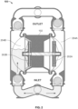
- FIGS. 3-5 depict various views of the leak detection device 106.
- FIG. 3 depicts a top cross-sectional view of the leak detection device 106 taken at axis A-A'.
- FIG. 4 depicts a side cross-sectional view of the leak detection device 106 taken at axis A-A'.
- FIG. 5 depicts an exploded diagram of the leak detection device 106.
- the drain channels 404 permit the liquid removed from the exhaust air by the liquid separator 304 to flow underneath tapered flange 326 and into the reservoir 318. This configuration may prevent liquid contained in the reservoir 318 from being re-entrained into exhaust air flowing through leak detection device 106.
- the air separator sleeve 322 includes one or more vent holes 328 to, for example, allow air to exit the channel 324 as liquid drains into the reservoir 318.
Landscapes
- Engineering & Computer Science (AREA)
- General Engineering & Computer Science (AREA)
- Mechanical Engineering (AREA)
- Physics & Mathematics (AREA)
- Fluid Mechanics (AREA)
- General Physics & Mathematics (AREA)
- Examining Or Testing Airtightness (AREA)
- Reciprocating Pumps (AREA)
Claims (12)
- Leckdetektionsvorrichtung für Membranpumpen (106), umfassend:einen Körper (302), umfassend:einen Luftstromeinlass (310),einen Luftstromauslass (312), der dazu angeordnet ist, mit dem Luftstromeinlass im Wesentlichen ausgerichtet zu sein, undeinen Flüssigkeitsbehälter (318) in einem unteren Abschnitt des Körpers;einen Flüssigkeitsabscheider (304), der direkt zwischen dem Luftstromeinlass und dem Luftstromauslass positioniert ist, wobei der Flüssigkeitsabscheider einen Luftströmungsweg vom Luftstromauslass in mindestens zwei getrennte Strömungswege um den Flüssigkeitsabscheider herum teilt, wobei der Flüssigkeitsabscheider (304) Folgendes umfasst:einen Zylinder, der mit dem Körper gekoppelt und direkt zwischen dem Luftstromeinlass und dem Luftstromauslass positioniert ist, undeine Hülse (322), die dazu ausgelegt ist, mit einem unteren Abschnitt des Zylinders gekoppelt zu sein, wobei die Hülse einen Kanal (324) umfasst, wobei ein erstes Ende des Kanals am unteren Abschnitt des Zylinders endet und sich ein zweites Ende des Kanals zum Flüssigkeitsbehälter hin öffnet; undeinen Füllstandsmesser (306), der zumindest teilweise in dem Kanal (324) enthalten ist, wobei der Kanal mit dem Flüssigkeitsbehälter in Flüssigkeitsverbindung steht.
- Leckdetektionsvorrichtung für Membranpumpen nach Anspruch 1, wobei der Füllstandsmesser eine Schwimmerschalteranordnung umfasst.
- Leckdetektionsvorrichtung für Membranpumpen nach Anspruch 2,
wobei die Schwimmerschalteranordnung einen Schwimmer (332) umfasst, der mit einem Schwimmersensor (330) wirkgekoppelt ist, wobei der Schwimmer in dem im unteren Abschnitt des Flüssigkeitsabscheiders definierten Kanal (324) aufgenommen ist. - Leckdetektionsvorrichtung für Membranpumpen nach Anspruch 3,
wobei sich der Schwimmersensor zumindest teilweise in den im unteren Abschnitt des Flüssigkeitsabscheiders definierten Kanal erstreckt. - Leckdetektionsvorrichtung für Membranpumpen nach Anspruch 1, wobei der Körper Folgendes umfasst:ein oberes Gehäuse (314), das den Luftstromeinlass und den Luftstromauslass umfasst; undein unteres Gehäuse (316), das den Flüssigkeitsbehälter definiert.
- Leckdetektionsvorrichtung für Membranpumpen nach Anspruch 1, wobei der Füllstandsmesser mit dem unteren Abschnitt des Zylinders gekoppelt ist und sich in den Kanal hinein erstreckt.
- Leckdetektionsvorrichtung für Membranpumpen nach Anspruch 4, wobei der Körper einen Vorsprung (402) umfasst, der über dem Flüssigkeitsbehälter positioniert ist, und
wobei die Hülse einen verjüngten Flansch in Kontakt mit dem Vorsprung umfasst, wobei der verjüngte Flansch (326) den Flüssigkeitsbehälter von einem Luftströmungsweg in einem oberen Abschnitt des Körpers abscheidet. - Leckdetektionsvorrichtung für Membranpumpen nach Anspruch 7,
wobei der Vorsprung mindestens einen Ablaufkanal umfasst, der die Flüssigkeitsverbindung zwischen dem Flüssigkeitsbehälter und dem Luftströmungsweg vorsieht. - Leckdetektionsvorrichtung für Membranpumpen nach Anspruch 8,
wobei der Körper Folgendes umfasst:ein oberes Gehäuse, umfassend:den Luftstromeinlass,den Luftstromauslass undden Luftströmungsweg zwischen dem Luftstromeinlass und dem Luftstromauslass undein unteres Gehäuse, das vom oberen Gehäuse trennbar ist und Folgendes umfasst:den Flüssigkeitsbehälter,den Vorsprung undden mindestens einen Ablaufkanal. - Leckdetektionsvorrichtung für Membranpumpen nach Anspruch 1,
wobei eine Fläche des Flüssigkeitsabscheiders eine direkte Aufprallfläche (320S) ausbildet und der Körper der Leckdetektionsvorrichtung für Membranpumpen dazu ausgelegt ist, den Luftstrom von der Abluftöffnung gegen die direkte Aufprallfläche zu leiten. - Membranpumpensystem (100), umfassend:eine luftbetriebene Membranpumpe (101), umfassend eine Luftventilanordnung (102) mit einer Abluftöffnung;die Leckdetektionsvorrichtung für Membranpumpen (106) nach einem der vorstehenden Ansprüche undeinen Schalldämpfer (108), umfassend einen Schalldämpfereinlass (114), der mit einem Luftstromauslass (312) der Leckdetektionsvorrichtung für Membranpumpen gekoppelt ist, wobei der Schalldämpfereinlass durch den Körper der Leckdetektionsvorrichtung für Membranpumpen im Wesentlichen mit der Abluftöffnung ausgerichtet ist,wobeider Flüssigkeitsabscheider (304) im Körper angeordnet ist, um den Luftstrom von der Abluftöffnung entlang zumindest zwei Strömungswegen um den Flüssigkeitsabscheider herum zum Schalldämpfereinlass zu leiten, undsich der Flüssigkeitsbehälter in einem unteren Abschnitt des Körpers befindet.
- Leckdetektionsverfahren für Membranpumpen, umfassend:Aufnehmen von Abluft von einer luftbetriebenen Membranpumpe (101) mittels einer Leckdetektionsvorrichtung (106);Entziehen von in der Abluft enthaltener Flüssigkeit durch die Verwendung eines Flüssigkeitsabscheiders (304), um eine Strömung der Abluft in mindestens zwei getrennte Strömungswege um den Flüssigkeitsabscheider herum zu leiten, wobei das Aufprallen der Abluft auf den Flüssigkeitsabscheider die Flüssigkeit aus der Abluft entzieht, und wobei der Flüssigkeitsabscheider Folgendes umfasst:einen Zylinder, der mit einem Körper (302) der Leckdetektionsvorrichtung gekoppelt und direkt zwischen einem Luftstromeinlass (310) und einem Luftstromauslass (312) des Körpers positioniert ist, undeine Hülse (322), die dazu ausgelegt ist, mit einem unteren Abschnitt des Zylinders gekoppelt zu sein, wobei die Hülse einen Kanal (324) umfasst, wobei ein erstes Ende des Kanals am unteren Abschnitt des Zylinders endet und sich ein zweites Ende des Kanals zu einem Flüssigkeitsbehälter (318) in einem unteren Abschnitt des Körpers hin öffnet;Leiten der Flüssigkeit in den unter dem Flüssigkeitsabscheider positionierten Flüssigkeitsbehälter undVorsehen eines Leckanzeigesignals, das auf die Aktivierung eines Schwimmerschalters reagiert, der zumindest teilweise in dem Kanal enthalten ist, wobei der Kanal mit dem Behälter in Flüssigkeitsverbindung steht.
Applications Claiming Priority (2)
| Application Number | Priority Date | Filing Date | Title |
|---|---|---|---|
| US16/731,287 US11149723B2 (en) | 2019-12-31 | 2019-12-31 | Diaphragm pump leak detection |
| PCT/US2020/067290 WO2021138308A1 (en) | 2019-12-31 | 2020-12-29 | Diaphragm pump leak detection |
Publications (3)
| Publication Number | Publication Date |
|---|---|
| EP4085197A1 EP4085197A1 (de) | 2022-11-09 |
| EP4085197A4 EP4085197A4 (de) | 2023-05-03 |
| EP4085197B1 true EP4085197B1 (de) | 2025-03-19 |
Family
ID=76546020
Family Applications (1)
| Application Number | Title | Priority Date | Filing Date |
|---|---|---|---|
| EP20910896.8A Active EP4085197B1 (de) | 2019-12-31 | 2020-12-29 | Leckdetektion für membranpumpen |
Country Status (7)
| Country | Link |
|---|---|
| US (2) | US11149723B2 (de) |
| EP (1) | EP4085197B1 (de) |
| JP (1) | JP7573619B2 (de) |
| CN (2) | CN114846240B (de) |
| CA (1) | CA3163296A1 (de) |
| ES (1) | ES3032787T3 (de) |
| WO (1) | WO2021138308A1 (de) |
Families Citing this family (3)
| Publication number | Priority date | Publication date | Assignee | Title |
|---|---|---|---|---|
| ES2970195T3 (es) * | 2019-01-10 | 2024-05-27 | Psg California Llc | Bomba neumática con conjunto de detección y contención de fugas |
| US11149723B2 (en) | 2019-12-31 | 2021-10-19 | Psg California Llc | Diaphragm pump leak detection |
| CN119554214A (zh) * | 2025-01-20 | 2025-03-04 | 临海市永昊真空设备有限公司 | 一种隔膜真空泵 |
Family Cites Families (65)
| Publication number | Priority date | Publication date | Assignee | Title |
|---|---|---|---|---|
| US2563211A (en) * | 1948-02-20 | 1951-08-07 | Cassese Salvatore | Liquid proportioner |
| US3152572A (en) * | 1963-02-12 | 1964-10-13 | Jr Henry W Allhoff | Leak indicator |
| US3467015A (en) * | 1968-03-28 | 1969-09-16 | Westinghouse Electric Corp | Hydraulic pump-motor combination |
| GB1480334A (en) * | 1973-07-09 | 1977-07-20 | Unilever Ltd | Safety valves for protection against liquid contamination |
| US3982609A (en) * | 1975-07-07 | 1976-09-28 | Chicago Pneumatic Tool Company | Air line lubricator |
| US4593530A (en) * | 1984-04-10 | 1986-06-10 | Air Products And Chemicals, Inc. | Method and apparatus for improving the sensitivity of a leak detector utilizing a cryopump |
| US4860788A (en) * | 1987-06-29 | 1989-08-29 | Kayaba Industry Co. Ltd. | Metering valve |
| US4953583A (en) * | 1989-03-24 | 1990-09-04 | Stant Inc. | Tank pressure control valve |
| US5096087A (en) * | 1989-08-02 | 1992-03-17 | Coretank, Inc. | Double containment and leak detection apparatus |
| US5469879A (en) * | 1994-05-23 | 1995-11-28 | Rasmussen; John | Condensate trap and drain for systems under pressure |
| US6572609B1 (en) * | 1999-07-14 | 2003-06-03 | Cardiofocus, Inc. | Phototherapeutic waveguide apparatus |
| US5501577A (en) | 1994-12-19 | 1996-03-26 | Cornell; Gary L. | Gas operated pump leak preventer |
| US5816778A (en) * | 1996-01-16 | 1998-10-06 | Micron Technology, Inc. | System for controlling the stroke length of a double-diaphragm pump |
| US5877689A (en) * | 1997-09-30 | 1999-03-02 | D'amico; Dan | Leak detector |
| CA2245082C (en) * | 1998-08-14 | 2001-02-06 | Gerald Francis Gallant | Float activated shutoff valve |
| US6190136B1 (en) * | 1999-08-30 | 2001-02-20 | Ingersoll-Rand Company | Diaphragm failure sensing apparatus and diaphragm pumps incorporating same |
| US6280149B1 (en) * | 1999-10-28 | 2001-08-28 | Ingersoll-Rand Company | Active feedback apparatus and air driven diaphragm pumps incorporating same |
| US6592126B2 (en) * | 2001-07-20 | 2003-07-15 | Flowserve Management Company | Mechanical seal leak detector |
| DE10345712A1 (de) * | 2003-10-01 | 2005-04-21 | Bosch Rexroth Ag | Druck-Einspeiseventil |
| EP1716361A1 (de) * | 2003-12-03 | 2006-11-02 | Taylor McLaren Limited | Wassereindringungfeststellungsvorrichtung |
| KR100764119B1 (ko) * | 2004-02-25 | 2007-10-08 | 볼보 컨스트럭션 이키프먼트 홀딩 스웨덴 에이비 | 파일럿 포펫형 릴리프 밸브 |
| US7490624B2 (en) * | 2004-03-31 | 2009-02-17 | Continental Automotive Canada, Inc. | Passive pressure activation valve |
| US7302964B1 (en) * | 2004-04-05 | 2007-12-04 | Siemens Vdo Automotive Canada Inc. | Housing for a liquid seal vacuum and pressure relief valve apparatus |
| US7198060B2 (en) * | 2004-05-05 | 2007-04-03 | Parker-Hannifin Corporation | Pressure relieving coupler manifold with internal velocity fuse |
| EP1602830A1 (de) * | 2004-06-02 | 2005-12-07 | Ailand Corporation S.A. | Hydraulisch angetriebene mehrzylindrige Kolbenpumpe |
| JP4252530B2 (ja) * | 2004-12-13 | 2009-04-08 | ダイキン工業株式会社 | 空気調和機のドレン水静菌構造 |
| US20070209705A1 (en) * | 2006-03-07 | 2007-09-13 | Nichols Randall W | Drain valve |
| US7964029B2 (en) * | 2006-07-17 | 2011-06-21 | Thar Instrument, Inc. | Process flowstream collection system |
| US7489253B2 (en) * | 2006-09-07 | 2009-02-10 | Kevin M. Murphy, Llc | Fluid detection and containment apparatus |
| US8643497B2 (en) * | 2006-09-07 | 2014-02-04 | Kevin M. Murphy, Llc | Integral fluid detection and containment apparatus |
| US20080135105A1 (en) * | 2006-12-07 | 2008-06-12 | Husky Injection Molding Systems Ltd. | Fluid Recovery System of Molding System |
| US8360096B2 (en) * | 2007-08-15 | 2013-01-29 | Sauer-Danfoss Inc. | Low pressure rise rate pilot operated poppet relief valve |
| JP2009108786A (ja) * | 2007-10-31 | 2009-05-21 | Kyosan Denki Co Ltd | プライミングポンプ |
| US7802587B1 (en) * | 2008-02-26 | 2010-09-28 | Ball Ralph A | Float valve and method |
| JP5265262B2 (ja) * | 2008-05-21 | 2013-08-14 | 株式会社パイオラックス | フロート弁装置 |
| WO2010085744A2 (en) * | 2009-01-23 | 2010-07-29 | Idex Aodd, Inc. | Method for increasing compressed air efficiency in a pump |
| CN201437770U (zh) | 2009-05-19 | 2010-04-14 | 上海江浪流体机械制造有限公司 | 一种气动隔膜泵成套定量控制设备 |
| US8147575B2 (en) * | 2009-09-09 | 2012-04-03 | Ingersoll-Rand Company | Multi-stage oil separation system including a cyclonic separation stage |
| US8430115B2 (en) * | 2010-01-05 | 2013-04-30 | Norman Thomas Stieb | Leak detection system for humidifier |
| US8926291B2 (en) | 2010-07-19 | 2015-01-06 | Michael Orndorff | Speed control for diaphragm pump |
| BR112013024593A2 (pt) * | 2011-05-11 | 2017-08-08 | Beko Tecnologies Gmbh | dreno de consensado para sistemas de gás pressurizado |
| US8939182B2 (en) * | 2011-08-16 | 2015-01-27 | Jay Vincent Lambke | Liquid collection system |
| JP5974261B2 (ja) * | 2011-09-12 | 2016-08-23 | パナソニックIpマネジメント株式会社 | ダイアフラムポンプの運転制御方法 |
| US9028224B2 (en) * | 2011-09-23 | 2015-05-12 | Tuthill Corporation | Air operated double diaphragm pump |
| JP6018842B2 (ja) * | 2012-08-29 | 2016-11-02 | 紀州技研工業株式会社 | ダイアフラムポンプおよびインクジェットプリンタ |
| JP2014169639A (ja) * | 2013-03-01 | 2014-09-18 | Tokiko Techno Kk | ポンプユニット |
| CN203146296U (zh) | 2013-03-26 | 2013-08-21 | 上海金树树脂粉末有限公司 | 空气隔膜泵隔膜漏液安全控制器 |
| CN103147971A (zh) | 2013-03-26 | 2013-06-12 | 上海金树树脂粉末有限公司 | 空气隔膜泵隔膜漏液安全控制器及其控制方法 |
| HK1190032A2 (en) * | 2013-05-07 | 2014-06-20 | 香港中华煤气有限公司 | Shut-off device for pipe |
| CN203272098U (zh) * | 2013-05-13 | 2013-11-06 | 上海金树树脂粉末有限公司 | 空气隔膜泵隔膜漏液指示器 |
| US9784381B2 (en) * | 2013-05-24 | 2017-10-10 | Eaton Corporation | Balanced poppet float vent valve |
| KR102181147B1 (ko) * | 2013-08-02 | 2020-11-20 | 가부시키가이샤 에코화스토 | 노즐식 스팀트랩 |
| US9845794B2 (en) * | 2013-10-08 | 2017-12-19 | Ingersoll-Rand Company | Hydraulically actuated diaphragm pumps |
| FR3021713B1 (fr) * | 2014-05-27 | 2019-04-05 | Milton Roy Europe | Pompe a membrane a commande hydraulique comprenant un chemin de degazage dedie |
| EP3523539B1 (de) * | 2016-11-01 | 2020-08-12 | PSG Worldwide, Inc. | Magnetisch gekoppelte dichtungslose kreiselpumpe |
| US20190078959A1 (en) * | 2017-09-14 | 2019-03-14 | Milton Roy, Llc | Solenoid Current Monitoring Method for Leak Detection and Vapor Lock |
| EP3460440A1 (de) * | 2017-09-20 | 2019-03-27 | Grundfos Holding A/S | Pumpendichtungleckagedetektionssystem |
| US10437269B1 (en) * | 2017-10-06 | 2019-10-08 | Sun Hydraulics, Llc | Electrohydraulic counterbalance and pressure relief valve |
| US10876881B2 (en) * | 2018-02-28 | 2020-12-29 | Halliburton Energy Services, Inc. | Apparatus and method for characterizing performance of pumps and verifying accurate operation of flowmeters |
| US11041493B2 (en) | 2018-04-11 | 2021-06-22 | Advanced Sensor Design Technologies, LLC | Methods and apparatus for monitoring triplex pumps |
| ES2970195T3 (es) | 2019-01-10 | 2024-05-27 | Psg California Llc | Bomba neumática con conjunto de detección y contención de fugas |
| US10683879B1 (en) * | 2019-01-22 | 2020-06-16 | Sun Hydraulics, Llc | Two-port electrohydraulic counterbalance valve |
| US10775812B1 (en) * | 2019-01-22 | 2020-09-15 | Sun Hydraulics, Llc | Inverse proportional pressure relief valve |
| US12110885B2 (en) * | 2019-02-28 | 2024-10-08 | Eddy Pump Corporation | Seal support sensor for a pump |
| US11149723B2 (en) | 2019-12-31 | 2021-10-19 | Psg California Llc | Diaphragm pump leak detection |
-
2019
- 2019-12-31 US US16/731,287 patent/US11149723B2/en active Active
-
2020
- 2020-12-29 JP JP2022540587A patent/JP7573619B2/ja active Active
- 2020-12-29 CA CA3163296A patent/CA3163296A1/en active Pending
- 2020-12-29 WO PCT/US2020/067290 patent/WO2021138308A1/en not_active Ceased
- 2020-12-29 CN CN202080089737.9A patent/CN114846240B/zh active Active
- 2020-12-29 CN CN202410787299.3A patent/CN118705167A/zh active Pending
- 2020-12-29 ES ES20910896T patent/ES3032787T3/es active Active
- 2020-12-29 EP EP20910896.8A patent/EP4085197B1/de active Active
-
2021
- 2021-10-07 US US17/450,218 patent/US11719359B2/en active Active
Also Published As
| Publication number | Publication date |
|---|---|
| EP4085197A1 (de) | 2022-11-09 |
| US11149723B2 (en) | 2021-10-19 |
| CN118705167A (zh) | 2024-09-27 |
| US11719359B2 (en) | 2023-08-08 |
| JP7573619B2 (ja) | 2024-10-25 |
| US20210199103A1 (en) | 2021-07-01 |
| CN114846240B (zh) | 2024-07-02 |
| JP2023508728A (ja) | 2023-03-03 |
| EP4085197A4 (de) | 2023-05-03 |
| CA3163296A1 (en) | 2021-07-08 |
| ES3032787T3 (en) | 2025-07-24 |
| WO2021138308A1 (en) | 2021-07-08 |
| US20220025878A1 (en) | 2022-01-27 |
| CN114846240A (zh) | 2022-08-02 |
Similar Documents
| Publication | Publication Date | Title |
|---|---|---|
| EP4085197B1 (de) | Leckdetektion für membranpumpen | |
| US6797040B2 (en) | Device for the separation of gas and liquid/solid particles in a mixture of gas and fluid/solid particles flowing in a line and method for the separation thereof | |
| US8590493B1 (en) | Systems and devices for separating water and contaminants from fuel | |
| US5501577A (en) | Gas operated pump leak preventer | |
| US20120195740A1 (en) | Drain Discharge Equipment for Compressor and Gas Turbine System | |
| HK40073773A (en) | Diaphragm pump leak detection | |
| HK40073773B (zh) | 隔膜泵泄漏检测 | |
| TWI855984B (zh) | 隔膜破損檢測裝置及往復泵裝置 | |
| CN219672856U (zh) | 一种用于干式真空泵机组的冷却系统 | |
| CN116877931B (zh) | 一种管道高负压环境下的气体流速及浓度的测量装置 | |
| CN211975396U (zh) | 压缩机或真空泵装置及其液体返回系统 | |
| TWI726667B (zh) | 壓縮機或真空泵裝置、用於此壓縮機或真空泵裝置之液體返回系統以及用於自此壓縮機或真空泵裝置的齒輪箱排出液體的方法 | |
| CN115218057B (zh) | 一种脉动阻尼器 | |
| KR20190000688U (ko) | 압축공기필터용 차압식과 플로트식 겸용 탄댐 오토드레인 장치 | |
| US12264995B2 (en) | Leak monitoring manifold for a pumping system | |
| JP6726956B2 (ja) | 往復動ポンプ及びガス抜き弁のバルブ構造 | |
| CN217785535U (zh) | 制冷设备气液分离器 | |
| CN106704678B (zh) | 复合式污水排气阀及污水排放系统 | |
| CN218522819U (zh) | 一种用于离心式气体压缩机的油雾分离系统 | |
| CN219848280U (zh) | 变压器用回油除气泡装置 | |
| CN101961577A (zh) | 一种化工泵过滤装置 | |
| KR20090117590A (ko) | 펌프장치 | |
| CN108457862B (zh) | 一种自吸装置及一种离心泵 | |
| CN204897384U (zh) | 一种加油机顶出油结构 | |
| CN119000194A (zh) | 一种便携式负压采气桶 |
Legal Events
| Date | Code | Title | Description |
|---|---|---|---|
| STAA | Information on the status of an ep patent application or granted ep patent |
Free format text: STATUS: THE INTERNATIONAL PUBLICATION HAS BEEN MADE |
|
| PUAI | Public reference made under article 153(3) epc to a published international application that has entered the european phase |
Free format text: ORIGINAL CODE: 0009012 |
|
| STAA | Information on the status of an ep patent application or granted ep patent |
Free format text: STATUS: REQUEST FOR EXAMINATION WAS MADE |
|
| 17P | Request for examination filed |
Effective date: 20220609 |
|
| AK | Designated contracting states |
Kind code of ref document: A1 Designated state(s): AL AT BE BG CH CY CZ DE DK EE ES FI FR GB GR HR HU IE IS IT LI LT LU LV MC MK MT NL NO PL PT RO RS SE SI SK SM TR |
|
| DAV | Request for validation of the european patent (deleted) | ||
| DAX | Request for extension of the european patent (deleted) | ||
| A4 | Supplementary search report drawn up and despatched |
Effective date: 20230403 |
|
| RIC1 | Information provided on ipc code assigned before grant |
Ipc: F04B 43/00 20060101ALI20230328BHEP Ipc: G01F 23/30 20060101ALI20230328BHEP Ipc: G01F 23/00 20220101ALI20230328BHEP Ipc: F04B 49/10 20060101ALI20230328BHEP Ipc: F04B 45/04 20060101ALI20230328BHEP Ipc: F04B 43/02 20060101ALI20230328BHEP Ipc: F04B 43/08 20060101AFI20230328BHEP |
|
| GRAP | Despatch of communication of intention to grant a patent |
Free format text: ORIGINAL CODE: EPIDOSNIGR1 |
|
| STAA | Information on the status of an ep patent application or granted ep patent |
Free format text: STATUS: GRANT OF PATENT IS INTENDED |
|
| RIC1 | Information provided on ipc code assigned before grant |
Ipc: F04B 43/00 20060101ALI20240930BHEP Ipc: G01F 23/30 20060101ALI20240930BHEP Ipc: G01F 23/00 20220101ALI20240930BHEP Ipc: F04B 49/10 20060101ALI20240930BHEP Ipc: F04B 45/04 20060101ALI20240930BHEP Ipc: F04B 43/02 20060101ALI20240930BHEP Ipc: F04B 43/08 20060101AFI20240930BHEP |
|
| INTG | Intention to grant announced |
Effective date: 20241011 |
|
| GRAS | Grant fee paid |
Free format text: ORIGINAL CODE: EPIDOSNIGR3 |
|
| GRAA | (expected) grant |
Free format text: ORIGINAL CODE: 0009210 |
|
| STAA | Information on the status of an ep patent application or granted ep patent |
Free format text: STATUS: THE PATENT HAS BEEN GRANTED |
|
| AK | Designated contracting states |
Kind code of ref document: B1 Designated state(s): AL AT BE BG CH CY CZ DE DK EE ES FI FR GB GR HR HU IE IS IT LI LT LU LV MC MK MT NL NO PL PT RO RS SE SI SK SM TR |
|
| REG | Reference to a national code |
Ref country code: GB Ref legal event code: FG4D |
|
| REG | Reference to a national code |
Ref country code: CH Ref legal event code: EP |
|
| REG | Reference to a national code |
Ref country code: IE Ref legal event code: FG4D |
|
| REG | Reference to a national code |
Ref country code: DE Ref legal event code: R096 Ref document number: 602020048140 Country of ref document: DE |
|
| P01 | Opt-out of the competence of the unified patent court (upc) registered |
Free format text: CASE NUMBER: APP_18589/2025 Effective date: 20250416 |
|
| PG25 | Lapsed in a contracting state [announced via postgrant information from national office to epo] |
Ref country code: RS Free format text: LAPSE BECAUSE OF FAILURE TO SUBMIT A TRANSLATION OF THE DESCRIPTION OR TO PAY THE FEE WITHIN THE PRESCRIBED TIME-LIMIT Effective date: 20250619 |
|
| PG25 | Lapsed in a contracting state [announced via postgrant information from national office to epo] |
Ref country code: FI Free format text: LAPSE BECAUSE OF FAILURE TO SUBMIT A TRANSLATION OF THE DESCRIPTION OR TO PAY THE FEE WITHIN THE PRESCRIBED TIME-LIMIT Effective date: 20250319 |
|
| REG | Reference to a national code |
Ref country code: LT Ref legal event code: MG9D |
|
| PG25 | Lapsed in a contracting state [announced via postgrant information from national office to epo] |
Ref country code: NO Free format text: LAPSE BECAUSE OF FAILURE TO SUBMIT A TRANSLATION OF THE DESCRIPTION OR TO PAY THE FEE WITHIN THE PRESCRIBED TIME-LIMIT Effective date: 20250619 |
|
| PG25 | Lapsed in a contracting state [announced via postgrant information from national office to epo] |
Ref country code: HR Free format text: LAPSE BECAUSE OF FAILURE TO SUBMIT A TRANSLATION OF THE DESCRIPTION OR TO PAY THE FEE WITHIN THE PRESCRIBED TIME-LIMIT Effective date: 20250319 |
|
| PG25 | Lapsed in a contracting state [announced via postgrant information from national office to epo] |
Ref country code: LV Free format text: LAPSE BECAUSE OF FAILURE TO SUBMIT A TRANSLATION OF THE DESCRIPTION OR TO PAY THE FEE WITHIN THE PRESCRIBED TIME-LIMIT Effective date: 20250319 |
|
| PG25 | Lapsed in a contracting state [announced via postgrant information from national office to epo] |
Ref country code: GR Free format text: LAPSE BECAUSE OF FAILURE TO SUBMIT A TRANSLATION OF THE DESCRIPTION OR TO PAY THE FEE WITHIN THE PRESCRIBED TIME-LIMIT Effective date: 20250620 Ref country code: BG Free format text: LAPSE BECAUSE OF FAILURE TO SUBMIT A TRANSLATION OF THE DESCRIPTION OR TO PAY THE FEE WITHIN THE PRESCRIBED TIME-LIMIT Effective date: 20250319 |
|
| REG | Reference to a national code |
Ref country code: ES Ref legal event code: FG2A Ref document number: 3032787 Country of ref document: ES Kind code of ref document: T3 Effective date: 20250724 |
|
| REG | Reference to a national code |
Ref country code: NL Ref legal event code: MP Effective date: 20250319 |
|
| REG | Reference to a national code |
Ref country code: AT Ref legal event code: MK05 Ref document number: 1777148 Country of ref document: AT Kind code of ref document: T Effective date: 20250319 |
|
| PG25 | Lapsed in a contracting state [announced via postgrant information from national office to epo] |
Ref country code: NL Free format text: LAPSE BECAUSE OF FAILURE TO SUBMIT A TRANSLATION OF THE DESCRIPTION OR TO PAY THE FEE WITHIN THE PRESCRIBED TIME-LIMIT Effective date: 20250319 |
|
| PG25 | Lapsed in a contracting state [announced via postgrant information from national office to epo] |
Ref country code: SE Free format text: LAPSE BECAUSE OF FAILURE TO SUBMIT A TRANSLATION OF THE DESCRIPTION OR TO PAY THE FEE WITHIN THE PRESCRIBED TIME-LIMIT Effective date: 20250319 |
|
| PG25 | Lapsed in a contracting state [announced via postgrant information from national office to epo] |
Ref country code: SM Free format text: LAPSE BECAUSE OF FAILURE TO SUBMIT A TRANSLATION OF THE DESCRIPTION OR TO PAY THE FEE WITHIN THE PRESCRIBED TIME-LIMIT Effective date: 20250319 |
|
| PG25 | Lapsed in a contracting state [announced via postgrant information from national office to epo] |
Ref country code: PT Free format text: LAPSE BECAUSE OF FAILURE TO SUBMIT A TRANSLATION OF THE DESCRIPTION OR TO PAY THE FEE WITHIN THE PRESCRIBED TIME-LIMIT Effective date: 20250721 |
|
| PG25 | Lapsed in a contracting state [announced via postgrant information from national office to epo] |
Ref country code: PL Free format text: LAPSE BECAUSE OF FAILURE TO SUBMIT A TRANSLATION OF THE DESCRIPTION OR TO PAY THE FEE WITHIN THE PRESCRIBED TIME-LIMIT Effective date: 20250319 |
|
| PG25 | Lapsed in a contracting state [announced via postgrant information from national office to epo] |
Ref country code: AT Free format text: LAPSE BECAUSE OF FAILURE TO SUBMIT A TRANSLATION OF THE DESCRIPTION OR TO PAY THE FEE WITHIN THE PRESCRIBED TIME-LIMIT Effective date: 20250319 |
|
| PG25 | Lapsed in a contracting state [announced via postgrant information from national office to epo] |
Ref country code: CZ Free format text: LAPSE BECAUSE OF FAILURE TO SUBMIT A TRANSLATION OF THE DESCRIPTION OR TO PAY THE FEE WITHIN THE PRESCRIBED TIME-LIMIT Effective date: 20250319 Ref country code: EE Free format text: LAPSE BECAUSE OF FAILURE TO SUBMIT A TRANSLATION OF THE DESCRIPTION OR TO PAY THE FEE WITHIN THE PRESCRIBED TIME-LIMIT Effective date: 20250319 |
|
| PG25 | Lapsed in a contracting state [announced via postgrant information from national office to epo] |
Ref country code: RO Free format text: LAPSE BECAUSE OF FAILURE TO SUBMIT A TRANSLATION OF THE DESCRIPTION OR TO PAY THE FEE WITHIN THE PRESCRIBED TIME-LIMIT Effective date: 20250319 |
|
| PG25 | Lapsed in a contracting state [announced via postgrant information from national office to epo] |
Ref country code: SK Free format text: LAPSE BECAUSE OF FAILURE TO SUBMIT A TRANSLATION OF THE DESCRIPTION OR TO PAY THE FEE WITHIN THE PRESCRIBED TIME-LIMIT Effective date: 20250319 |
|
| PG25 | Lapsed in a contracting state [announced via postgrant information from national office to epo] |
Ref country code: IS Free format text: LAPSE BECAUSE OF FAILURE TO SUBMIT A TRANSLATION OF THE DESCRIPTION OR TO PAY THE FEE WITHIN THE PRESCRIBED TIME-LIMIT Effective date: 20250719 |
|
| REG | Reference to a national code |
Ref country code: DE Ref legal event code: R097 Ref document number: 602020048140 Country of ref document: DE |
|
| PGFP | Annual fee paid to national office [announced via postgrant information from national office to epo] |
Ref country code: DE Payment date: 20251210 Year of fee payment: 6 |
|
| PGFP | Annual fee paid to national office [announced via postgrant information from national office to epo] |
Ref country code: GB Payment date: 20251211 Year of fee payment: 6 |
|
| PG25 | Lapsed in a contracting state [announced via postgrant information from national office to epo] |
Ref country code: DK Free format text: LAPSE BECAUSE OF FAILURE TO SUBMIT A TRANSLATION OF THE DESCRIPTION OR TO PAY THE FEE WITHIN THE PRESCRIBED TIME-LIMIT Effective date: 20250319 |
|
| PGFP | Annual fee paid to national office [announced via postgrant information from national office to epo] |
Ref country code: IT Payment date: 20251219 Year of fee payment: 6 |
|
| PGFP | Annual fee paid to national office [announced via postgrant information from national office to epo] |
Ref country code: FR Payment date: 20251222 Year of fee payment: 6 |
|
| PLBE | No opposition filed within time limit |
Free format text: ORIGINAL CODE: 0009261 |
|
| STAA | Information on the status of an ep patent application or granted ep patent |
Free format text: STATUS: NO OPPOSITION FILED WITHIN TIME LIMIT |
|
| REG | Reference to a national code |
Ref country code: CH Ref legal event code: L10 Free format text: ST27 STATUS EVENT CODE: U-0-0-L10-L00 (AS PROVIDED BY THE NATIONAL OFFICE) Effective date: 20260128 |
|
| 26N | No opposition filed |
Effective date: 20251222 |
|
| PGFP | Annual fee paid to national office [announced via postgrant information from national office to epo] |
Ref country code: ES Payment date: 20260119 Year of fee payment: 6 |