EP4084986B1 - Elektrisch angetriebene selbstfahrende maschine - Google Patents
Elektrisch angetriebene selbstfahrende maschine Download PDFInfo
- Publication number
- EP4084986B1 EP4084986B1 EP20845625.1A EP20845625A EP4084986B1 EP 4084986 B1 EP4084986 B1 EP 4084986B1 EP 20845625 A EP20845625 A EP 20845625A EP 4084986 B1 EP4084986 B1 EP 4084986B1
- Authority
- EP
- European Patent Office
- Prior art keywords
- machine
- bearing frame
- ground
- electric
- power supply
- Prior art date
- Legal status (The legal status is an assumption and is not a legal conclusion. Google has not performed a legal analysis and makes no representation as to the accuracy of the status listed.)
- Active
Links
Images


Classifications
-
- B—PERFORMING OPERATIONS; TRANSPORTING
- B60—VEHICLES IN GENERAL
- B60L—PROPULSION OF ELECTRICALLY-PROPELLED VEHICLES; SUPPLYING ELECTRIC POWER FOR AUXILIARY EQUIPMENT OF ELECTRICALLY-PROPELLED VEHICLES; ELECTRODYNAMIC BRAKE SYSTEMS FOR VEHICLES IN GENERAL; MAGNETIC SUSPENSION OR LEVITATION FOR VEHICLES; MONITORING OPERATING VARIABLES OF ELECTRICALLY-PROPELLED VEHICLES; ELECTRIC SAFETY DEVICES FOR ELECTRICALLY-PROPELLED VEHICLES
- B60L9/00—Electric propulsion with power supply external to the vehicle
-
- A—HUMAN NECESSITIES
- A01—AGRICULTURE; FORESTRY; ANIMAL HUSBANDRY; HUNTING; TRAPPING; FISHING
- A01B—SOIL WORKING IN AGRICULTURE OR FORESTRY; PARTS, DETAILS, OR ACCESSORIES OF AGRICULTURAL MACHINES OR IMPLEMENTS, IN GENERAL
- A01B63/00—Lifting or adjusting devices or arrangements for agricultural machines or implements
- A01B63/14—Lifting or adjusting devices or arrangements for agricultural machines or implements for implements drawn by animals or tractors
- A01B63/24—Tools or tool-holders adjustable relatively to the frame
- A01B63/32—Tools or tool-holders adjustable relatively to the frame operated by hydraulic or pneumatic means without automatic control
-
- A—HUMAN NECESSITIES
- A01—AGRICULTURE; FORESTRY; ANIMAL HUSBANDRY; HUNTING; TRAPPING; FISHING
- A01B—SOIL WORKING IN AGRICULTURE OR FORESTRY; PARTS, DETAILS, OR ACCESSORIES OF AGRICULTURAL MACHINES OR IMPLEMENTS, IN GENERAL
- A01B69/00—Steering of agricultural machines or implements; Guiding agricultural machines or implements on a desired track
- A01B69/007—Steering or guiding of agricultural vehicles, e.g. steering of the tractor to keep the plough in the furrow
- A01B69/008—Steering or guiding of agricultural vehicles, e.g. steering of the tractor to keep the plough in the furrow automatic
-
- A—HUMAN NECESSITIES
- A01—AGRICULTURE; FORESTRY; ANIMAL HUSBANDRY; HUNTING; TRAPPING; FISHING
- A01B—SOIL WORKING IN AGRICULTURE OR FORESTRY; PARTS, DETAILS, OR ACCESSORIES OF AGRICULTURAL MACHINES OR IMPLEMENTS, IN GENERAL
- A01B76/00—Parts, details or accessories of agricultural machines or implements, not provided for in groups A01B51/00 - A01B75/00
-
- A—HUMAN NECESSITIES
- A01—AGRICULTURE; FORESTRY; ANIMAL HUSBANDRY; HUNTING; TRAPPING; FISHING
- A01B—SOIL WORKING IN AGRICULTURE OR FORESTRY; PARTS, DETAILS, OR ACCESSORIES OF AGRICULTURAL MACHINES OR IMPLEMENTS, IN GENERAL
- A01B79/00—Methods for working soil
- A01B79/005—Precision agriculture
-
- B—PERFORMING OPERATIONS; TRANSPORTING
- B60—VEHICLES IN GENERAL
- B60K—ARRANGEMENT OR MOUNTING OF PROPULSION UNITS OR OF TRANSMISSIONS IN VEHICLES; ARRANGEMENT OR MOUNTING OF PLURAL DIVERSE PRIME-MOVERS IN VEHICLES; AUXILIARY DRIVES FOR VEHICLES; INSTRUMENTATION OR DASHBOARDS FOR VEHICLES; ARRANGEMENTS IN CONNECTION WITH COOLING, AIR INTAKE, GAS EXHAUST OR FUEL SUPPLY OF PROPULSION UNITS IN VEHICLES
- B60K11/00—Arrangement in connection with cooling of propulsion units
- B60K11/06—Arrangement in connection with cooling of propulsion units with air cooling
-
- B—PERFORMING OPERATIONS; TRANSPORTING
- B62—LAND VEHICLES FOR TRAVELLING OTHERWISE THAN ON RAILS
- B62D—MOTOR VEHICLES; TRAILERS
- B62D55/00—Endless track vehicles
- B62D55/06—Endless track vehicles with tracks without ground wheels
-
- B—PERFORMING OPERATIONS; TRANSPORTING
- B62—LAND VEHICLES FOR TRAVELLING OTHERWISE THAN ON RAILS
- B62D—MOTOR VEHICLES; TRAILERS
- B62D55/00—Endless track vehicles
- B62D55/08—Endless track units; Parts thereof
- B62D55/14—Arrangement, location, or adaptation of rollers
-
- A—HUMAN NECESSITIES
- A01—AGRICULTURE; FORESTRY; ANIMAL HUSBANDRY; HUNTING; TRAPPING; FISHING
- A01B—SOIL WORKING IN AGRICULTURE OR FORESTRY; PARTS, DETAILS, OR ACCESSORIES OF AGRICULTURAL MACHINES OR IMPLEMENTS, IN GENERAL
- A01B49/00—Combined machines
- A01B49/02—Combined machines with two or more soil-working tools of different kind
- A01B49/027—Combined machines with two or more soil-working tools of different kind with a rotating, soil working support element, e.g. a roller
-
- B—PERFORMING OPERATIONS; TRANSPORTING
- B60—VEHICLES IN GENERAL
- B60L—PROPULSION OF ELECTRICALLY-PROPELLED VEHICLES; SUPPLYING ELECTRIC POWER FOR AUXILIARY EQUIPMENT OF ELECTRICALLY-PROPELLED VEHICLES; ELECTRODYNAMIC BRAKE SYSTEMS FOR VEHICLES IN GENERAL; MAGNETIC SUSPENSION OR LEVITATION FOR VEHICLES; MONITORING OPERATING VARIABLES OF ELECTRICALLY-PROPELLED VEHICLES; ELECTRIC SAFETY DEVICES FOR ELECTRICALLY-PROPELLED VEHICLES
- B60L2200/00—Type of vehicles
- B60L2200/40—Working vehicles
-
- B—PERFORMING OPERATIONS; TRANSPORTING
- B62—LAND VEHICLES FOR TRAVELLING OTHERWISE THAN ON RAILS
- B62D—MOTOR VEHICLES; TRAILERS
- B62D55/00—Endless track vehicles
- B62D55/08—Endless track units; Parts thereof
- B62D55/18—Tracks
- B62D55/20—Tracks of articulated type, e.g. chains
Definitions
- the current invention relates to an electric powered self-propelled driving machine, commonly known in agriculture as "agricultural tractor” and forming a vehicle used not only in agriculture, but also, for example, in the fields of gardening, do-it-yourself and urban care to tow a trailer or hook up specific equipment to carry out agricultural or civil work or to arrange outdoor public or private environments.
- the electric powered self-propelled driving machine of the invention does not house any battery pack, for example under the hood (as is found in some electric powered agricultural machines of the known art) and can also be defined as autonomous, in the sense that it is moved following a prefixed and programmed scheme of working the ground, without a person driving the agricultural driving machine (not surprisingly, such an agricultural machine of the invention lacks a driver's cab from where, in a traditional agricultural machine widespread on the market for decades, the operator supervises the ground working operations by driving or in any case managing the machine itself).
- the self-propelled driving machines used in agriculture today mostly consist of vehicles provided with a diesel motor, which, therefore, use diesel as the driving force, the same fuel which is banned in many urban centers; in many cases, these agricultural machines are obsolete vehicles, which therefore do not have technological equipment capable of reducing the emissions which negatively impact the atmosphere in the environment.
- An electric powered agricultural machine certainly does not have the consumption of a diesel-powered tractor, and for what matters most, it involves zero emissions of polluting or harmful gases: this is a detail of no small importance, if it is considered that the polluting discharges produced during the working of a ground by a normal tractor with a combustion engine end up directly on the agricultural production.
- the dimensions of the battery-powered electric power supply are enormous, substantially unthinkable, as they provide exactly the opposite of the need when working particular agricultural crops, such as vineyards, where the small size of the agricultural machinery is crucial in order to reduce the working times.
- the innovative, designed, autonomous electric agricultural machine powered by a cable is capable, at least in hypothesis given the prototype status thereof, to exploit the electricity by means of a continuous cable-type power supply, thus eliminating the limited duration of the electric charge accumulators which is causing so many problems, highlighted above, during practical use and also avoiding the forced machine stops to perform recharges or replacements which such accumulators bring.
- a cable-powered electric agricultural machine currently disclosed in the industry requires a 2,500 V AC power source and uses an electric connection cable which continuously transfers electricity at a power of about 300 kW and through which it's possible to connect the machine itself to the auxiliary service column, present at field edge and connected to the electricity network.
- the electric powered agricultural machine in question includes a reference drum (or rotor or winder) installed at the front part thereof, substantially cantilevered with respect to the bearing frame, which houses the electric cable for a predefined length which, again in pure hypothesis, reaches up to 1,000 meters and is configured as an electric coil with a horizontal axis, parallel to the ground.
- a reference drum or rotor or winder
- such an electric powered agricultural machine of the known art follows a predefined working pattern, in fully automatic mode, while the electric power supply cable coil is unwound from and rewound onto the reference rotor (or unwinder) with the aid of a robotic support arm, so as to ensure friction-free operation with limited mechanical stress.
- the agricultural driving machine of the known art electrically powered by cable, can also be driven manually by an operator, but remotely using a remote control, a solution which is useful when, for example, the agricultural machine is being maneuvered to start the work at field edge.
- the empty weight of the electric cable powered agricultural machine is substantially equivalent to the weight of a conventional agricultural tractor, however it is capable of supplying, advantageously, double the power.
- the electric cable powered self-propelled agricultural machine offers the advantages of silent operation and a total absence of harmful gas emissions, in addition to having, as already partially highlighted, about 50% lower production and operating costs than battery-powered agricultural machines.
- the main drawback derives from the fact that the wound coil of electric cable is positioned in the front part of the bearing frame of the driving machine and this aspect, in fact, also prevents the application of equipment for working the ground (be it an agricultural field, a lawn of a sports stadium, a public or private garden) in such a front part, possibly simultaneously with the work equipment which is, however, regularly and exclusively applicable to the rear part of the driving machine.
- a second drawback of the electric powered self-propelled machines, generally agricultural, of the known art is that the length of the electric cable must be kept low, and not exceed about 1,000 meters, in order to avoid dangerously unbalancing the vehicle weight towards the front: this limits the width of the field of ground which can be worked with such driving tractor machines, starting from the connecting point of the electric cable to the auxiliary service column at field edge itself.
- a further drawback of the electric cable powered self-propelled driving machines, generally agricultural, of a known type is the fact that during the maneuvering step at field edge, at the end of the working of a given band of ground and before starting the working of the next and directly adjacent one, it is necessary to carry out laborious and articulated maneuvers of the vehicle, including reversing, with the negative consequence not only of generating an evident useless waste of time and of reducing the working efficiency, but also of trampling with the vehicle, in particular with the rear wheels thereof, a freshly worked part of the ground and the electric cable itself.
- a last but not least drawback of the electric cable powered self-propelled driving machines for working a ground of the prior art is due to the fact that, both because the electric cable coil is mounted in the front part of the bearing frame of such vehicles and for intrinsic construction (seen for example in US3,632,906 A ), it is necessary to couple to the bearing frame itself special and articulated mechanical support and return systems of the electric cable which distance it away from the vehicle, keeping it laterally spaced from the latter's dimensions, especially during the advancement of the vehicle on the ground being worked, to try as much as possible to avoid (without however preventing, as just highlighted) the electric cable from interfering, even getting entangled, with the wheels or with the bearing frame of the vehicle and thereby unfavorably wearing.
- the present invention aims to effectively overcome such drawbacks.
- the cognitive sphere of the aforesaid main purpose it is the task of the invention to provide a self-propelled driving machine for working a ground, with electric traction or power, which allows to carry out simultaneously several workings on the same ground.
- It is a further task of the invention to create an electric powered self-propelled driving machine for working a ground which, as a function of the main purpose set out above, reduces the complete working time of a given ground plot and, in turn, has a better working performance than that of the driving machines of the known art comparable thereto.
- the electric powered self-propelled driving machine of the present invention allows to mount temporarily a piece of equipment for working the ground also in the front part of the bearing frame thereof; if required, this simultaneously occurs with a piece of work equipment mounted in the rear part of the bearing frame, with the foresight that the rear equipment and front equipment perform complementary and compatible operations (for instance fertilizing and ploughing, in agriculture).
- the generally agricultural electric powered self-propelled driving machine for working a ground therefore receives two sets of tools thanks to the front and rear attachments, resulting extremely versatile also for this reason: indeed, it allows ploughing, tilling the ground, preparing the seedbed, sowing and weeding with remarkable precision, simultaneously carrying out two of these processes (for example preparation and sowing of the ground), as long as they are compatible with each other.
- the reference rotor and the electric coil associated therewith are arranged in the central part of the bearing frame so that both the front part and the rear part of such a bearing frame are free from the front and directly facing the external environment in order to both be able to accommodate removably, and possibly simultaneously, equipment for working the ground.
- the reference rotor supporting the power supply cable is arranged in the center of the agricultural tractor machine of the invention, allowing operations to be carried out at 360°, ensuring the working continuity and making better use of the power supply cable compared to the driving machines of the prior art, since it is extended or unwound on the ground only to follow the exact length of the ground plot which is being worked on with the tool (or tools).
- the power supply cable always remains at the side of the machine even during the advancement thereof over the ground during the working step, without ever being an obstacle for the same, also potential, to be taken into account in operating conditions.
- the electric powered self-propelled driving machine for working a ground of the present invention requires, preferably but not bindingly, an electric power supply ranging from 20 kW to 50 kW in order to operate; the power supply cable of the machine can be connected to a common 380 Volt system, allowing the energy to flow to the agricultural machine of the invention which can thus start working continuously and autonomously, also throughout the day, while an operator remotely supervises the operation thereof.
- the electric powered self-propelled driving machine of the invention effectively and safely supports a power supply cable coil which, precisely because it is installed in the center of the bearing frame, has a greater length than that of the power supply cable installed on the equivalent machines of the prior art: this is reflected in the possibility of working without interruption, therefore more efficiently, larger plots of ground than those workable with the known electric powered agricultural tractors.
- the electric powered self-propelled driving machine for working a ground of the invention is provided with an unwinder (or first rotation means) cooperating with an electric coil formed by a power supply cable having a length of over 1,000 meters, up to even 1,500 meters.
- the positioning thereof in the central part of the bearing frame, as occurs in the machine of the invention advantageously allows to design a power supply cable with a section (i.e., diameter) wider than that one of similar machines of the prior art, thus obtaining, on one hand, the transfer of greater electric power since the electric current conducted is greater, and on the other hand, a limitation of the overheating and wear thereof.
- the electricity flows along the power supply cable, passes through the initial section of the distribution arm and arrives in the coil positioned at the center of the agricultural machine where it operates two electric motors, each having, preferably, the 44 kW of power and air-cooled, and form the "beating core" of the agricultural machine itself: through speed variation means, the epicyclic gears that regulate the power of the two electric motors are actuated, allowing the speed of the tractor machine of the invention to be adapted to the type of working which must be performed, significantly increasing the precision and effectiveness of the machine itself.
- speed of the self-propelled driving machine of the current invention can reduce to 500 m/h (which corresponds to 200 rpm of the two motors), while for lighter agricultural work such as sowing, sanding and/or fertilization, the self-propelled driving machine of the invention reaches up to 6 Km/h (corresponding to 1,480 rpm of the two motors).
- the electric powered self-propelled driving machine of the present invention is preferably provided with GPS technology which allows it to program its movements in a precise manner, creating a map of the ground to be worked.
- the GPS system allows the electric powered agricultural machine of the invention to always keep the position of the power supply cable under control, even while it is being unwound in the field.
- the receiver of the GPS system is positioned at the central support turret, more precisely inside the reference rotor, and therefore at the center of the tractor machine of the invention and allows the latter to independently determine the path to follow, know at any time the position of the power supply cable, adjusting the movement of the distribution arm accordingly and, if the equipment - such as a fertilizer spreader - it supports contains a product to be dispersed on the ground and it progressively loses weight precisely because during the working this product is spread on the ground, constantly update the center of gravity thereof to maintain stability during the advancement of the agricultural machine and/or during the maneuvering of the equipment at the edge of the field.
- the equipment - such as a fertilizer spreader - it supports contains a product to be dispersed on the ground and it progressively loses weight precisely because during the working this product is spread on the ground, constantly update the center of gravity thereof to maintain stability during the advancement of the agricultural machine and/or during the maneuvering of the equipment at the edge of the field.
- the electric powered self-propelled driving machine for working a ground of the invention changes the direction of travel: in fact, the hydraulic part of the machine comes into action, which first raises the tool, or even tools (in the case of front tool and rear tool), with which it is working the ground and then lowers an anchoring (or lifting) platform (or plate) which, thereby, enters in contact with the ground, discharging a large part of the weight of the agricultural machine of the invention to the ground.
- the bearing frame and the kinematic mechanisms of the self-propelled tractor of the invention are rotated by 90°, for example clockwise, and, once the anchoring or lifting platform is raised, the agricultural machine moves towards the next longitudinal band of ground to be worked - for a traversal section corresponding to the width of the tool with which the ground is being worked -, where the platform itself is lowered again and the frame carrying the kinematic mechanisms rotated by a further 90° always in the same direction of the previous rotation (for example clockwise).
- the anchoring (or lifting) platform is then raised and falls within the overall dimensions of the bearing frame of the agricultural machine of the invention and the tool (or tools, if one is installed in the front and one in the rear) are lowered: the electric powered self-propelled driving machine of the invention is thus ready to resume the work thereof, rewinding in the central part, in total safety, the power supply cable through the distribution arm.
- the electric powered driving machine is further provided with motion and temperature sensors which allow the identification of any obstacles present on the advancement path of the agricultural machine itself: in the remote but not totally avoidable case of collision with an obstacle (such as an animal), the operator remotely controlling the agricultural tractor machine receives a signal, for example on his smartphone, and possibly also a video of the situation which has arisen in the work field, by virtue of the detection means, such as a video camera, with which the machine of the invention is provided.
- the detection means such as a video camera
- the usually agricultural self-propelled driving machine of the present invention is state-of-the-art, sustainable and producible at a competitive cost; by virtue of the use of GPS technology and reduced forward speeds, through the invention it is possible to obtain greater precision in fundamental workings such as, for example, sowing and weeding: thereby, the use of fertilizers and herbicides is limited with respect to the known technique, resulting in economic savings and environmental benefits.
- the multifunctionality of the generally agricultural electric powered self-propelled driving machine of the invention makes it suitable and adaptable to different types of crops and also makes it perfect for the market, given the complex biodiversity of the workable territory to produce raw materials for the food industry.
- an agricultural tractor to which the present invention refers preferably, belonging to the family of self-propelled agricultural machines, is considered a “driving machine”, while the agricultural equipment carrying out the work on the ground pulled by such a tractor (such as the plough or the grubbing machine) or hooked to the power take-off thereof (such as the fertilizer spreader, the harrow, the tiller or the weeder) are defined as “operating machines”.
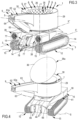
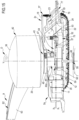
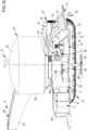
- the self-propelled driving machine of the invention useful for working a ground, such as an agricultural field by exploiting an electric power supply without any aid from electricity accumulators, is shown in figures 2-6 where it is globally numbered with 1, while figure 1 diagrammatically shows the mode of operation, while it is working the ground.
- the reference rotor 6, and the electric coil 7 wound thereon are arranged in the central part 2a of the bearing frame 2 so that both the front part 2b and rear part 2c of the bearing frame 2 themselves are frontally free and directly facing the external environment in order to accommodate, removably and, specifically simultaneously, both pieces of equipment L 1 (in this case a harrow) and L 2 (in this case a subsoiler with roller) for working the ground T.
- L 1 in this case a harrow
- L 2 in this case a subsoiler with roller
- the reference rotor 6 and the electric coil 7 wound thereon are always arranged at the weight gravity center defined by the bearing frame 2 and by the equipment (or tools) L 1 , L 2 for working the ground T removably installed on the bearing frame 2 itself; this therefore even when, in operating conditions, the product contained in (at least one) piece of work equipment - obviously different from those shown in the accompanying figures - mounted on the driving machine of the invention is progressively consumed, as it is spread on the ground T for the cultivation of the latter.
- This technical feature is a significant advantage for the stability of the electric powered self-propelled driving machine 1 of the invention, with respect to that offered by the known art, of which US3,632,906 A is a typical example.
- the reference rotor 6 preferably defines a vertical rotation axis Y around which the electric coil 7 is wound/unwound during the advancement of the driving machine 1 on the ground T.
- the reference rotor can define a horizontal rotation axis around which the electric power supply cable coil is wound/unwound during the advancement of the driving machine on the ground: this variant is particularly suitable for electric powered self-propelled driving machines with a width of no more than 3.5 meters.
- the driving machine 1 of the invention requires an electric power supply - supplied by the electricity grid and made available to the auxiliary service column E located at the edge B of the plot P of the ground T to be worked - having an electrical power in the range 20 ⁇ 50 kW and a voltage of 380 Volts.
- the value of the electric current is raised to 700 Volts by means of convenient electric current transformers to allow the design and construction of a power supply cable 5 with an adequately reduced section, more contained with respect to that otherwise required.
- the central processing and control unit is electrically connected to the electric power supply source E and, moreover, it manages the actuation and operation at least (although not only, as will be deduced from what is indicated below) of the electric motorization means 3 and of the first rotation means 8.
- the kinematic mechanisms 3 comprise a pair of tracks 12, 13 opposite to each other which are symmetrically arranged with respect to a longitudinal axis X according to which the bearing frame 2 is mainly articulated from a constructional point of view and each extend along a respective linear direction X', X" parallel to such a longitudinal axis X.
- Each of such tracks 12, 13 comprises, as per constructional praxis, a modular chain 14 provided with rigid ridges (or blocks or grooves) 15 monolithic thereto and made of metallic material of high mechanical strength, such as steel, thus being particularly suitable for more invasive working of the ground T - especially in the agricultural industry where the ground T is moreover uneven or irregular -, where therefore a greater adherence of the tracks 12, 13 and a significantly reduced resistance to advancement (or rolling friction) is required.
- each of said tracks comprises a modular chain provided with rigid monolithic ridges and made of elastomeric material of high mechanical strength, particularly suitable for working said ground in the civil, private and/or residential field.
- the electric motorization means 4 include a pair of electric motors 16, 17 arranged in the rear part 2c of the bearing frame 2 and symmetrically with respect to the longitudinal axis X of the latter just defined above.
- each of such electric motors 16, 17 is of the type with about 45 kW (so that the driving machine 1 develops a total power of about 120 HP) and is arranged above a respective of the tracks 12, 13.
- each of the electric motors 16, 17 is contained in a box-shaped protective body 18 which is arranged above each of the tracks 12, 13 and has the function of physically isolating the electric motors 16, 17 from the external environment, thus avoiding that any person, even those responsible for the works, accidentally and dangerously come into contact with said electric motors 16, 17 when the machine 1 is in use conditions or in any case available for use, for example in a farm shed.
- the electric motorization means 4 electrically cooperate with electric current conversion devices, indicated as a whole with 19 and seen in greater detail in figure 7 , adapted to:
- the electric current conversion devices 19 comprise a pair of inverters, only one of which is seen in the accompanying figures where it is indicated with 20, contained into the technical room 11 defined in the bearing frame 2: each of such electric current conversion devices 19 is electrically connected, on one side, to the central processing and control unit which manages the operation thereof, and, on the other side, to a respective electric motor 16, 17.
- the electric current conversion devices 19 of the type included in the invention also have the function of reducing the intensity of the electric current coming from the auxiliary service column E positioned at the edge B of the plot P of the ground T.
- the speed variation means 21 and the motion transmission means are suitable to vary the advancement speed of the driving machine 1 of the invention on the ground T according to the type of work to be carried out on the ground T itself.
- the rotation speed of the electric motors 16, 17 is made to vary from about 200 rpm to about 1,500 rpm, which corresponds to an advancement speed of the driving machine 1 of the invention on the ground T which varies from 500 m/h to 6 Km/h: this is based on the frequency impressed by the central processing and control unit introduced above.
- the speed variation means 21 comprise, for each of the electric motors 16, 17, a V-belt 22 closed in a ring, and a pair of pulleys 23, 24, spaced apart from each other and having rotation axes parallel to each other, in the annular groove 25 of which the aforesaid V-belt 22 is engaged in a variable position, according to speed requirements.
- the motion transmission means comprise a pair of cyclic gears (or gearings), also known as planetary and satellite gears and used for changing speeds in vehicles, one for each of the tracks 12, 13.
- the power supply cable 5 In relation to the power supply cable 5, it is of the three-phase type and has a diameter between 38 and 45 mm, preferably 42 mm: the constructional expedient related to these values of the diameter of the power supply cable 5 contributes, together with other expedients highlighted in the rest of the description, to avoid dangerous and harmful overheating.
- the power supply cable 5 advantageously has a length varying between 1,000 meters - particularly suitable for a smaller version of the driving machine 1 of the invention, provided with tracks made of elastomeric material, such as rubber, and with which it is possible to perform works on plots P of ground T of approximately 100 hectares, for example mowing the grass of a football field - and 1,500 meters - particularly suitable for a larger version of the driving machine 1 of the invention, provided with tracks made of metallic material, such as steel, and with which it is possible to perform works on plots P of ground T of approximately 225 hectares, for example ploughing and fertilizing agricultural ground -.
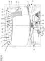
- the reference rotor 6 As far as the reference rotor 6 is concerned, it is supported by a structural assembly 74 belonging to the bearing frame 2 and arranged in particular in the central part 2a of such a bearing frame 2.
- the reference rotor 6 includes, preferably but not exclusively, an internally hollow cylindrical drum 26, provided with side containment flanges 27, 28 and having a frusto-conical or tapered shape along the linear rotation axis Y defined by the reference rotor 6: this expedient has the double significant advantage, on the one hand, of winding the power supply cable 5 outside the cylindrical drum 26 without overlapping some of the sections thereof and, on the other hand, to prevent that when the driving machine 1 is stationary, for example stored in a shed on a farm or in a garage or in a shed of a private house, the power supply cable 5 wound on the cylindrical drum 26 decants or slides down where it would cluster in a disordered manner.
- cylindrical drum 26 has a dimensional extension in height and width such as to help avoid dangerous and harmful overheating of the power supply cable 5 while it is wound/unwound onto/from a side wall 26a of the cylindrical drum 26.
- the internally hollow cylindrical drum 26 of the reference rotor 6 presents, advantageously although purely preferred, a height in the range 900 ⁇ 1,100 mm (preferably equal to 1,000 mm), an internal diameter in the range 1,100-1,300 mm (preferably equal to 1,200 mm) in the widest part, and an internal diameter in the range 900-1,100 mm (preferably equal to 1,000 mm) in the narrowest part.
- dimensional values are suitable for helping avoid dangerous and harmful overheating of the power supply cable 5 while it is wound/unwound onto/from the side wall 26a of the cylindrical drum 26, when the power supply cable presents a length of 1,500 m and the driving machine 1 of the invention is configured, for all intents and purposes, as an agricultural machine used for working fields destined to produce crops.
- the electric powered self-propelled driving machine of the invention is configured as a machine for less heavy work - which can be carried out in the field of gardening, do-it-yourself, urban care or public or private structures such as the field of a stadium -
- the internally hollow cylindrical drum of the reference rotor will continue to have a tapered shape but will have lower values than those indicated above, having to support an electric power supply cable coil of shorter predefined length: in this case, the height of the cylindrical drum will be in the range 200 ⁇ 400 mm (preferably equal to 300 mm) and have an internal diameter in the range 700 ⁇ 900 mm (preferably equal to 800 mm) in the widest part.
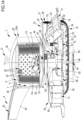
- the reference rotor 6, as mentioned rotated to unwind/wind the power supply cable 5, is also coaxially housed inside a central support turret 29 coupled to the bearing frame 2 and defining with the aforesaid reference rotor 6 an inner annular chamber 30 partly occupied by the power supply cable 5 and adapted to allow the passage of clean air A coming from the outside.
- the driving machine 1 of the invention comprises distribution means, as a whole numbered with 31 and visible in figures 10 , 11 and 14 , contained into the inner annular chamber 30 and coupled externally to the reference rotor 6 or internally to the central turret support 29, cooperating with the supply cable 5 to advantageously distribute it in a uniform and orderly manner on the side wall 6a of the reference rotor 6, according to a tapered configuration which leaves the inner annular chamber 30 at least partly free.
- the distribution means 31 comprise, for example, an endless screw 32 which is arranged vertically in the inner annular chamber 30 and in which an internally threaded adjustment block 33 progressively engages, while the power supply cable 5 is unwound/wound from/onto the reference rotor 6.
- the inner volume 34 of the central support turret 29 advantageously communicates with the technical room 11 of the bearing frame 2 through suitable structural slots (not visible in the accompanying figures) defined among the inner components of the driving machine 1 of the invention, as well as, in turn, such a technical room 11 conveniently communicates with the electric motorization means 4.
- the side wall 6a of the reference rotor 6 (or better, in the specific case, the side wall 26a of the cylindrical drum 26) presents a plurality of through openings 35 adapted to allow the passage of clean air A coming from the outside.
- the clean air A entering from above and in the central part of the machine 1 itself, firstly cools the power supply cable 5 which, by induction, inevitably tends to overheat while being wound/unwound from/onto the reference rotor 6; from here the clean air A, passing through the through openings 35 and the inner volume 34 of the reference rotor 6, conveniently enters inside the bearing frame 2, cooling the other sensitive components as well, as will be more apparent from what will be briefly highlighted.
- the reference rotor 6 is also provided with a covering dome 36, seen in figures 2 , 4 and 14-17 , protruding annularly (for about 5 cm) from an outer edge 6b of the reference rotor 6 to allow clean air A to enter the inner annular chamber 30; the covering dome 36 is suitable for being moved, for example by means of hydraulic actuators (not shown for brevity), between a normally taken closed position (seen in figures 14-17 ) and a temporarily taken open position (seen in figures 2 and 4 ).
- the covering dome 36 has a convex shape and is provided externally with lighting means, not shown in the accompanying drawings, adapted to be activated during the night operation of the driving machine 1 of the invention to signal the presence thereof.
- the driving machine 1 of the invention also comprises pneumatic suction means, indicated overall with 37, coupled to the bearing frame 2 near the electric motorization means 4, adapted to be operated to suck in the clean air A coming from the outside from above, making it circulate inside the bearing frame 2 to obtain the result of cooling the components subject to overheating.
- pneumatic suction means indicated overall with 37, coupled to the bearing frame 2 near the electric motorization means 4, adapted to be operated to suck in the clean air A coming from the outside from above, making it circulate inside the bearing frame 2 to obtain the result of cooling the components subject to overheating.
- the pneumatic suction means 37 are electrically connected to the central processing and control unit which manages the operation thereof and comprise, for example, a pair of axial fans 38, 39, each of which:
- the axial fans 38, 39 are operatively connected to temperature sensors, not shown, electrically connected to the central processing and control unit and adapted to enable the actuation of the axial fans 38, 39 (by the central processing and control unit) when a prefixed temperature threshold value inside the bearing frame 2 is exceeded.
- the central processing and control unit actuates the pneumatic suction means 37 which suck clean air A from the top of the central support turret 29, drawing the same clean air A through the substantially annular interspace 42 defined between the outer edge 29a of the central turret 29 and the inner edge 36a of the covering dome 36 and determining the conveyance thereof through, in the order:
- the central support turret 29, from which the distribution arm 9 protrudes and through which the distribution arm 9 itself is coupled to the bearing frame 2 is coupled by second rotation means, numbered overall 43, to a tubular element 44 (seen in figures 4-6 and 14-17 ) coupled to the bearing frame 2 and coaxial to the reference rotor 6 and to the central turret 29.
- the second rotation means 43 integral with the tubular element 44, preferably comprise:
- This constructional expedient has the advantage of keeping the power supply cable 5 distanced from the bearing frame 2 and from the work equipment L 1 , L 2 of the driving machine 1 of the invention, avoiding that the power supply cable 5 hinders the movement of the kinematic mechanisms 3 or negatively interferes with the latter during the maneuvers at the edge B of the field, as well as arranging the power supply cable 5 in the correct position useful to start the subsequent working of the longitudinal band F 2 directly adjacent to the one just worked (band F 1 ).
- the auxiliary electric motorization means 47 are electrically connected to the central processing and control unit and include, for example, an electric motor 48 of the low voltage type, such as a brushless motor.
- the self-propelled driving machine 1 of the present invention advantageously further comprises a lifting or anchoring platform (or plate) 49, preferably having a continuous profile, for example circular, a full structure (without recesses, carvings, or points of structural discontinuity) and identifying a horizontal plane; the lifting platform 49 is coupled to the first gear wheel 45 by means of first actuation means, indicated overall with 50, and adapted to be operated to arrange the lifting platform 49 selectively between:
- the first actuation means 50 comprise a first hydraulic cylinder 51 operating along a vertical axis, coinciding in this case with the linear rotation axis Y of the reference rotor 6, fixed to the central point 145a of a lower face 45a of the first gear wheel 45 (which can also be defined as fifth wheel) and at the central point 149a of an upper face 49a of the lifting platform 49 and hydraulically connected to an oil tank 52 coupled to a reinforcing base 53 belonging to the bearing frame 2 and positioned at the rear part 2c of the latter.
- tubular element 44 supporting the central support turret 29 is coupled to the bearing frame 2 by means of second actuation means, overall indicated with 54, adapted to be operated:
- Such horizontal sliding of the just-cited components forms an example of a constructional expedient, totally absent in the prior art (see document US3,632,096 A for instance), by which the reference rotor 6 and the electric coil 7 are kept wound thereon always at the weight gravity center defined by the bearing frame 2 and by the equipment L 1 , L 2 for working the ground T, advantageously conferring stability to the driving machine 1 of the invention and safety both for the structural integrity thereof and for the operators who can gravitate around it.
- the second actuation means 54 comprise, in this preferred case, a pair of second hydraulic cylinders 55, 56, each of which operating along a horizontal axis X 1 , X 2 and fixed to a protruding support bracket 57 and to a transversal reinforcing bar 58 of the bearing frame 2 coupled (for example by junction means such as a welding seam 59) also to an external wall 44a of the tubular element 44.
- Each of the second hydraulic cylinders 55, 56 is also hydraulically connected to the oil tank 52 present in the reinforcing base 53 of the bearing frame 2.
- alternative variants of the electric powered self-propelled driving machine of the invention may include that the second actuation means comprise a number of second hydraulic actuators different from that just described, this number being able to vary according to the constructional choices starting from one.
- the advantageous and innovative horizontal sliding of the central support turret 29, of the reference rotor 6 and of the electric coil 7 wound thereon to re-calibrate the weight gravity center of the driving machine 1 of the invention always occurs towards the part of the driving machine 1 itself in which the weight is greater, considering the fact that the weight gravity center of the latter, in operating conditions, is a function of the weight and position (front or rear) of the mounted work equipment (or, as in the case just described, of the weight of the work equipment L 1 , L 2 mounted at the front and rear), and of the consumption of product deriving from the working of the ground T, if at least one piece of work equipment (such as a fertilizer spreader) plans to spread product on the ground T, thus progressively losing weight.
- work equipment such as a fertilizer spreader
- both the first actuation means 50 and the second actuation means 54 is also managed by the central processing and control unit installed in the electrical panel 10 arranged in the technical room 11 which can be inspected.
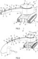
- distribution arm 9 With specific reference to the distribution arm 9, it should be highlighted that it supports the power supply cable 5 slidingly through convenient sliding means, overall indicated with 60, contained within the overall dimensions of the distribution arm 9.
- the sliding means 60 include a plurality of idle rollers 61 made of low friction coefficient material (for example a polymeric material such as PTFE, PET, POM, PEEK, combinations thereof and the like), two by two facing each other and spaced apart so as to define a longitudinal channel 62 for the passage of the power supply cable 5 within the overall dimensions of the distribution arm 9.
- low friction coefficient material for example a polymeric material such as PTFE, PET, POM, PEEK, combinations thereof and the like
- the idle rollers 61 are arranged two by two so as to define linear directions Z 1 , Z 2 converging each other in order to prevent the accidental and inconvenient separation of the power supply cable 5 from the distribution arm 9.
- the distribution arm 9 is of the foldable type, being divided into a plurality of shaped portions 63 having an inner volume 63a communicating with the external environment; each of such shaped portions 63 is coupled to the adjacent one having greater dimensions through a rotation hinge 64 adapted to arrange said distribution arm 9 alternately in:
- the distribution arm 9 in the rest position, has the minimum length, shown for example in figures 3 and 4 , and each of the shaped portions 63 is partially and rotatably retracted into the other one directly adjacent thereto, so as to minimize the overall dimensions of the distribution arm 9, for example during transport or while it is stored in a farm shed.
- the first rotation means 8 preferably comprise an inner gear 67 supported by the bearing frame 2 and operatively connected to one of the rotation shafts of one of the kinematic mechanisms 3 through a main hydraulic control unit, numbered overall with 68, adapted to be operated by such a rotation shaft to rotate the reference rotor 6 around the linear axis Y:
- figures 10 and 14 show that the inner gear 67 includes, purely by way of example:
- the main hydraulic control unit 68 comprises two hydraulic pumps, not shown, keyed to one of the rotation shafts of one of the kinematic mechanisms 3: during the maneuver at field edge B, one hydraulic pump rotates in one direction while the other hydraulic pump rotates in the opposite direction so that the oil supplied to the reference rotor 6 is zeroed: by doing so, this essential component of the driving machine 1 of the invention remains stationary, without rotating, while at field edge B the rotation of the kinematic mechanism 3, of the bearing frame 2 by a first angle of 90° and, after a short transversal path of length equal to the width of the work equipment L 1 , L 2 , by a second angle of 90°.
- the aforesaid type of connection between the first rotation means 8 and the kinematic mechanisms 3 makes the rotation speed of the reference rotor 6 supporting the electric coil 7 proportional to the speed of the kinematic mechanisms 3, in particular of the tracks 12, 13 which preferentially compose them.
- the driving machine 1 of the invention also comprises an auxiliary hydraulic control unit, indicated overall with 75, coupled to the bearing frame 2 at the rear part 2c and operatively connected to the oil tank 52 coupled to the reinforcing base 53 of the bearing frame 2, adapted to be operated to move the work equipment L 1 , L 2 arranged in the front part 2b and/or in the rear part 2c of the bearing frame 2.
- an auxiliary hydraulic control unit indicated overall with 75, coupled to the bearing frame 2 at the rear part 2c and operatively connected to the oil tank 52 coupled to the reinforcing base 53 of the bearing frame 2, adapted to be operated to move the work equipment L 1 , L 2 arranged in the front part 2b and/or in the rear part 2c of the bearing frame 2.
- the auxiliary hydraulic control unit 75 comprises, in this case, a hydraulic pump, not shown for simplicity, submerged in the oil tank 52 and a respective electric service motor 76 coupled to the reinforcing base 53 and electrically connected to the central processing and control unit.
- the auxiliary hydraulic control unit may also comprise two submerged hydraulic pumps: this solution is particularly suitable when work equipment (such as a multi-plough) provided with multiple mechanisms must be used, some of which can be operated separately and autonomously by others to perform the most correct and effective working of the ground possible.
- work equipment such as a multi-plough
- the oil tank 52 supplies the users including the first hydraulic cylinder 51, the second hydraulic cylinders 55, 56 and the hydraulic cylinders 77, 78, the latter arranged in this case only in the rear part 2c of the bearing frame 2 and useful for lifting and lowering the work equipment L 2 mounted in the rear part 2c.
- auxiliary hydraulic unit 75 that is electrically connected to the central processing and control unit which governs the operation thereof and which is present in the control panel 10 arranged in the technical room 11.
- the driving machine 1 of the invention comprises an electronic receiver for positioning and assisted satellite navigation 79, seen in figures 10 and 14 , which:
- the electronic satellite receiver 79 is a classic GPS receiver (acronym for "Global Positioning System”), provided with a so-called “active” type of assisted navigation technology, contained in the reference rotor 6, arranged at the linear rotation axis Y of the latter and supported by the structural group 74 of the bearing frame 2.
- the electronic satellite receiver 79 is a GPS receiver integral with the first actuation means 50 and arranged at a central point 145b of an upper face 45b, opposite to the lower face 45a, of the first gear wheel 45 belonging to the second rotation means 8.
- FIGS 7 and 17 also show the presence of a transformer 80 useful to reduce the intensity of the electric current supplied at 220 V to the service components such as solenoid valves, central processing and control unit, lighting means and so on.
- a transformer 80 useful to reduce the intensity of the electric current supplied at 220 V to the service components such as solenoid valves, central processing and control unit, lighting means and so on.
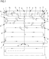
- Figure 1 shows in a simplified manner the working diagram which can be effectively and advantageously exploited and, for all intents and purposes, followed by the driving machine 1 of the invention, which cannot be achieved with the driving machines of known type, powered by an electric cable connected to an electricity source: compared to these ones, the driving machine 1 of the invention allows almost to half the consumption required to work a given plot P of ground T.
- the self-propelled driving machine 1 of the present invention is conveniently although not necessarily guided from the reference point R to the starting point I by traveling empty, without carrying out any work on the ground, firstly the first path T 1 at the central part N of the plot P of ground T and subsequently the second path T 2 , transversal to the first path T 1 , at a first side field edge G, according to the travel direction given by the respective arrows.
- the driving machine 1 of the invention is moved keeping the rear part 2c in front with respect to the travel direction, given by the arrows T 1 , T 2 , as if proceeding in reverse, while the power supply cable 5 is unwound by the reference rotor 6.
- the invention driving machine 1 without having to perform any maneuver, is ready to start working the longitudinal band F 1 of the plot P of ground T with the work equipment L 1 , L 2 thereof, already having the front part 2b of the bearing frame 2 in front and the distribution arm 9 to the right of the bearing frame 2, frontally thereto and to the work equipment L 1 , in respect to the advancement direction of the driving machine 1 on the ground T.
- the driving machine 1 therefore works the first section of the first longitudinal band F 1 , guided by the GPS based on the cross-linked navigation program set in the central processing and control unit and rewinding the power supply cable 5 around the reference rotor 6 until it reaches the central part N.
- the central processing and control unit operates the low voltage-type electric motor 48 of the auxiliary electric motorization means 47, thus obtaining the prompt and rapid clockwise rotation, by an angle of about 90°, of the central support turret 29 (and therewith of the distribution arm 9) while the driving machine 1 advances with the front part 2b of the bearing frame 2 arranged in front, unwinding the supply cable again from the reference rotor 6.
- the distribution arm 9 changes the position thereof with respect to the bearing frame 2 and with respect to the travel direction of the driving machine 1 of the invention, moving behind the bearing frame 2 while remaining to the right of the latter: in similar conditions, the second section is worked, aligned in sequence with respect to the first section of which it is the continuation, of the first longitudinal band F 1 up to the first end point U, symmetrically opposite to the starting point I, at field edge B.
- the self-propelled driving machine 1 of the invention is moved according to what has been described above in relation to, in the order:
- the invention driving machine 1 is thus immediately ready to work the longitudinal band F 2 directly adjacent to the first longitudinal band F 1 just worked following the exact same operating mode just described for the band F 1 , continuing, in particular, for the first section of the band F 2 (up to the central part N) again with the front part 2b of the bearing frame 2 in front and the distribution arm 9 to the right of the bearing frame 2, in front thereto and to the work equipment L 1 , in respect to the advancement direction of the driving machine 1 on the ground T.
- the working of the entire plot P of ground T is completed following this operating sequence, in a short time, with maximum operating efficiency and without the aid of any operator on board the self-propelled driving machine 1 of the invention.
- the first rotation means may have different constructional composition and position in the overall dimensions of the bearing frame of the machine from those described above in relation to the preferred embodiment of the invention.
- an electric powered self-propelled driving machine provided, specifically, essentially with the lifting platform (and together therewith, in particular, the central support turret) described above, operatively connected to the first actuation means acting in a vertical direction, to place it alternately in a lowered position close to the ground and in a raised position therefrom when it reaches the field edge of the ground while working and it is thus required to reverse the advancement direction of the machine itself, could be the subject of any separate, dedicated and independent patent by filing a divisional application including a specific formulation of the main and independent claim which generically claims the aforesaid technical concept.
- an electric powered self-propelled driving machine specifically provided essentially with means for guiding the reference rotor (and therewith not only the electric power supply cable coil but also, particularly, the central support turret), operatively connected to second actuation means acting in a horizontal direction, could be the subject of a possible separate, dedicated and independent patent by filing a divisional application including a specific formulation of the main and independent claim which generically claims the aforesaid technical concept.
- an electric powered self-propelled driving machine specifically provided essentially with means for conveying the cooling air both for the power supply cable and the electrical panel, means for converting electricity (such as inverters) and electric motorization means could be the subject of a possible separate, dedicated and independent by filing a divisional application including a specific formulation of the main and independent claim which generically claims the aforesaid technical concept.
- an electric powered self-propelled driving machine essentially provided with a distribution arm which can be folded back thereon, as it consist of a plurality of tubular portions two by two rotatably coupled each other through a rotation hinge arranging the distribution arm alternately in the operating position and in the rest position previously defined, could be the subject of a separate and independent patent by filing a divisional application including a specific formulation of the main and independent claim which generically claims the aforesaid technical concept.
- Another potential subject of an independent and separate patent, through the related filing of a divisional application substantially based on the technical material described here is also an electric powered self-propelled driving machine generally claiming a mechanical system which allows the regular, rapid, and effective reverse movement thereof without causing dangerous and harmful interference with the power supply cable.
Landscapes
- Engineering & Computer Science (AREA)
- Life Sciences & Earth Sciences (AREA)
- Mechanical Engineering (AREA)
- Transportation (AREA)
- Soil Sciences (AREA)
- Environmental Sciences (AREA)
- Combustion & Propulsion (AREA)
- Chemical & Material Sciences (AREA)
- Sustainable Development (AREA)
- Sustainable Energy (AREA)
- Power Engineering (AREA)
- Zoology (AREA)
- Agricultural Machines (AREA)
Claims (43)
- Elektrisch angetriebene selbstfahrende Antriebsmaschine (1) zur Bearbeitung eines Bodens (T), umfassend:- einen Trägerrahmen (2), der geeignet ist, um in einem vorgegebenen Abstand von einer Referenzfläche (S) zu bleiben, wenn die Maschine (1) zusammengebaut ist;- kinematische Mechanismen (3), die mit dem Trägerrahmen (2) gekoppelt und geeignet sind, um in der Nähe der Referenzfläche (S) angeordnet zu sein, wenn sich die Maschine (1) im Betriebszustand befindet;- elektrische Motorisierungsmittel (4), die mit dem Trägerrahmen (2) gekoppelt und mit den kinematischen Mechanismen (3) wirkverbunden sind und geeignet sind, um elektrisch betrieben zu werden, um den Trägerrahmen (2) zu bewegen;- ein Stromversorgungskabel (5), das geeignet ist, um elektrisch mit den elektrischen Motorisierungsmitteln (4) verbunden zu werden und mit einer Stromversorgungsquelle (E) verbunden zu werden;- einen Referenzrotor (6), um den das Stromversorgungskabel (5) gewickelt ist, um eine elektrische Spule (7) mit vordefinierter Länge zu bilden, der mit dem Trägerrahmen (2) gekoppelt und mit ersten Drehmitteln (8) wirkverbunden ist, die geeignet sind, um betrieben zu werden, um das Stromversorgungskabel (5) zumindest während der Fortbewegung der Antriebsmaschine (1), während sie einen Boden (T) bearbeitet, von dem/auf den Referenzrotor (6) abzuwickeln/aufzuwickeln;- einen Verteilerarm (9), der mit dem Trägerrahmen (2) wirkverbunden ist und das Stromversorgungskabel (5) trägt, um zumindest die Interferenz desselben mit den kinematischen Mechanismen (3) während der Fortbewegung der Antriebsmaschine (1) auf dem Boden (T) zu begrenzen, wobei der Referenzrotor (6) und die darauf gewickelte elektrische Spule (7) in dem mittleren Teil (2a) des Trägerrahmens (2) angeordnet sind, so dass sowohl der vordere Teil (2b) als auch der hintere Teil (2c) des Trägerrahmens (2) frontal frei sind und direkt der äußeren Umgebung zugewandt sind, so dass sie dazu konfiguriert sind, sowohl vordere als auch hintere Ausrüstungsteile (L1, L2) zur Bearbeitung des Bodens (T) abnehmbar aufzunehmen, dadurch gekennzeichnet, dass der Referenzrotor (6) und die darauf gewickelte elektrische Spule (7) immer in dem durch den Trägerrahmen (2) und die Ausrüstung (L1, L2) zur Bearbeitung des Bodens (T) definierten Gewichtsschwerpunkt positioniert sind.
- Maschine nach Anspruch 1), dadurch gekennzeichnet, dass der Referenzrotor eine lineare Drehachse definiert, um die die elektrische Spule während der Fortbewegung der Antriebsmaschine aufgewickelt/abgewickelt wird und die horizontal ist.
- Maschine (1) nach Anspruch 1), dadurch gekennzeichnet, dass der Referenzrotor (6) eine lineare Drehachse (Y) definiert, um die die elektrische Spule (7) während der Fortbewegung der Antriebsmaschine (1) aufgewickelt/abgewickelt wird und die vertikal ist.
- Maschine (1) nach einem der vorhergehenden Ansprüche, dadurch gekennzeichnet, dass sie eine zentrale Verarbeitungs- und Steuereinheit umfasst, die in einem Steuerpult (10) installiert ist, das in einem in dem Trägerrahmen (2) hergestellten Technikraum (11) angeordnet ist und die geeignet ist, um mit einer Stromversorgungsquelle (E) elektrisch verbunden zu werden und die Betätigung und den Betrieb zumindest der elektrischen Motorisierungsmittel (4) und der ersten Drehmittel (8) zu steuern.
- Maschine (1) nach einem der vorhergehenden Ansprüche, dadurch gekennzeichnet, dass die kinematischen Mechanismen (3) ein Paar einander gegenüberliegender Raupenketten (12, 13) umfassen, die in Bezug auf eine Längsachse (X) des Trägerrahmens (2) symmetrisch angeordnet sind und sich jeweils entlang einer linearen Richtung (X', X") parallel zu der Längsachse (X) erstrecken.
- Maschine (1) nach Anspruch 5), dadurch gekennzeichnet, dass jede der Raupenketten (12, 13) eine modulare Kette (14) umfasst, die mit fest verbundenen starren Rippen (15) versehen ist und aus einem metallischen Material mit hoher mechanischer Festigkeit besteht.
- Maschine nach Anspruch 5), dadurch gekennzeichnet, dass jede der Raupenketten eine modulare Kette umfasst, die mit starren, fest verbundenen Rippen versehen ist und aus einem Elastomermaterial mit hoher mechanischer Festigkeit besteht.
- Maschine (1) nach einem der vorhergehenden Ansprüche, dadurch gekennzeichnet, dass die elektrischen Motorisierungsmittel (4) ein Paar Elektromotoren (16, 17) umfassen, die in dem hinteren Teil (2c) des Trägerrahmens (2) und symmetrisch in Bezug auf eine Längsachse (X) des Trägerrahmens (2) angeordnet sind.
- Maschine (1) nach Anspruch 8), wenn abhängig von Anspruch 5), dadurch gekennzeichnet, dass jeder der Elektromotoren (16, 17) in einem kastenförmigen Schutzkörper (18) enthalten ist, der über jeder der Raupenketten (12, 13) angeordnet und geeignet ist, um ihn von der äußeren Umgebung physisch zu isolieren.
- Maschine (1) nach einem der vorhergehenden Ansprüche, dadurch gekennzeichnet, dass die elektrischen Motorisierungsmittel (4) elektrisch mit Stromumwandlungsvorrichtungen (19) zusammenwirken, die dazu geeignet sind:• zwischen einer Stromversorgungsquelle (E) und den elektrischen Motorisierungsmitteln (4) zu stehen;• differenziert betrieben zu werden, um zumindest die kinematischen Mechanismen (3) und den Trägerrahmen (2) und möglicherweise die Bearbeitungsausrüstung (L1, L2) um einen Winkel von 180° zu drehen, wenn die Maschine (1), sobald die Bearbeitung eines Längsbandes (F1) einer Parzelle (P) des Bodens (T) beendet ist, den Rand (B) der Parzelle (P) des Bodens (T) erreicht, und die Maschine (1) in der Position zu platzieren, die nützlich ist, um die Bearbeitung des nächsten und unmittelbar benachbarten Längsbands (F2) der Parzelle (P) des Bodens (T) zu beginnen.
- Maschine (1) nach Anspruch 10), wenn abhängig von Anspruch 8) und Anspruch 4), dadurch gekennzeichnet, dass die Stromumwandlungsvorrichtungen (19) ein Paar von Wechselrichtern (20) umfassen, die in dem in dem Trägerrahmen (2) definierten Technikraum (11) enthalten sind und von denen jeder auf einer Seite mit der zentralen Verarbeitungs- und Steuereinheit, die deren Betrieb steuert, und auf der anderen Seite mit einem jeweiligen der Elektromotoren (16, 17) elektrisch verbunden ist.
- Maschine (1) nach einem der vorhergehenden Ansprüche, dadurch gekennzeichnet, dass die elektrischen Motorisierungsmittel (4) mit den kinematischen Mechanismen (3) wirkverbunden sind durch:- Geschwindigkeitsänderungsmittel (21), die im inneren Teil des Trägerrahmens (2) enthalten sind;- Bewegungsübertragungsmittel, die im inneren Teil der kinematischen Mechanismen (3) enthalten sind,die geeignet sind, um die Fortbewegungsgeschwindigkeit der Maschine (1) auf dem Boden (T) gemäß der auf dem Boden (T) auszuführenden Art der Bearbeitung zu ändern.
- Maschine (1) nach Anspruch 12), wenn abhängig von Anspruch 8), dadurch gekennzeichnet, dass die Geschwindigkeitsänderungsmittel (21) für jeden der Elektromotoren (16, 17) einen Keilriemen (22), der in einem Ring geschlossen ist, und ein Paar Riemenscheiben (23, 24) umfassen, die voneinander beabstandet sind und zueinander parallele Drehachsen aufweisen und in die der Keilriemen (23) eingreift.
- Maschine (1) nach Anspruch 12), wenn abhängig von Anspruch 5), dadurch gekennzeichnet, dass die Übertragungsmittel ein Paar epizyklischer Zahnräder umfassen, eines für jede der Raupenketten (12, 13).
- Maschine nach einem der vorhergehenden Ansprüche, dadurch gekennzeichnet, dass das Stromversorgungskabel (5) vom Dreiphasen-Typ ist und einen Durchmesser zwischen 38 und 45 mm aufweist.
- Maschine (1) nach einem der vorhergehenden Ansprüche, dadurch gekennzeichnet, dass der Referenzrotor (6) durch eine Struktureinheit (74), die zu dem Trägerrahmen (2) gehört und in dem mittleren Teil (2a) des Trägerrahmens (2) angeordnet ist, getragen wird.
- Maschine (1) nach einem der vorhergehenden Ansprüche, dadurch gekennzeichnet, dass der Referenzrotor (6) eine innen hohle zylindrische Trommel (26) umfasst, die mit seitlichen Aufnahmeflanschen (27, 28) versehen ist und eine kegelstumpfförmige oder konische Form entlang einer linearen Drehachse (Y), die durch den Referenzrotor (6) definiert ist, und eine Dimensionsausdehnung in Höhe und Breite aufweist, die geeignet ist, um bei der Vermeidung einer gefährlichen Überhitzung des Stromversorgungskabels (5) zu unterstützen, während es auf eine/von einer Seitenwand (26a) der zylindrischen Trommel (26) aufgewickelt/abgewickelt wird.
- Maschine (1) nach einem der vorhergehenden Ansprüche, dadurch gekennzeichnet, dass der Referenzrotor (6) gedreht wird, um das Stromversorgungskabel (5) abzuwickeln/aufzuwickeln, und koaxial in einem mittleren Stützturm (29) untergebracht ist, der mit dem Trägerrahmen (2) gekoppelt ist und mit dem Referenzrotor (6) eine innere ringförmige Kammer (30) definiert, die teilweise von dem Stromversorgungskabel (5) eingenommen wird und geeignet ist, um den Durchgang von sauberer Luft (A), die von außen kommt, zu ermöglichen.
- Maschine (1) nach Anspruch 18), dadurch gekennzeichnet, dass sie Verteilermittel (31) umfasst, die in der inneren ringförmigen Kammer (30) enthalten sind und außen an den Referenzrotor (6) oder innen an den mittleren Stützturm (29) gekoppelt sind und mit dem Stromversorgungskabel (5) zusammenwirken, um es gleichmäßig und ordentlich auf eine Seitenwand (6a) des Referenzrotors (6) gemäß einer konischen Konfiguration zu verteilen, die die innere ringförmige Kammer (30) zumindest teilweise frei lässt.
- Maschine (1) nach Anspruch 18) oder 19), wenn abhängig von Anspruch 4), dadurch gekennzeichnet, dass das Innenvolumen (34) des mittleren Stützturms (29) mit dem Technikraum (11) des Trägerrahmens (2) in Verbindung steht und der Technikraum (11) mit den elektrischen Motorisierungsmitteln (4) in Verbindung steht.
- Maschine (1) nach einem der vorhergehenden Ansprüche, dadurch gekennzeichnet, dass eine Seitenwand (6a) des Referenzrotors (6) eine Vielzahl von Durchgangsöffnungen (35) aufweist, die geeignet sind, um den Durchgang von sauberer Luft (A), die von außen kommt, zu ermöglichen.
- Maschine (1) nach einem der Ansprüche 19), 20) oder 21), dadurch gekennzeichnet, dass der Referenzrotor (6) mit einer Abdeckkuppel (36) versehen ist, die fast ringförmig von einer Außenkante (26a) des mittleren Turms (29) hervorsteht, um den Eintritt der Luft (A) in die innere ringförmige Kammer (30) zu ermöglichen, und die geeignet ist, um zwischen einer normalerweise eingenommenen geschlossenen Position und einer vorübergehend eingenommenen offenen Position bewegt zu werden.
- Maschine (1) nach Anspruch 22), dadurch gekennzeichnet, dass die Abdeckkuppel (36) eine abgerundete Form aufweist und außen mit Beleuchtungsmitteln versehen ist, die geeignet sind, um während des Nachtbetriebs der Maschine (1) betrieben zu werden, um ihre Anwesenheit zu signalisieren.
- Maschine (1) nach einem der vorhergehenden Ansprüche, dadurch gekennzeichnet, dass sie pneumatische Ansaugmittel (37) umfasst, die mit dem Trägerrahmen (2) in der Nähe der elektrischen Motorisierungsmittel (4) gekoppelt sind und geeignet sind, um betrieben zu werden, um saubere Luft (A), die von außen kommt, von oben anzusaugen und im Inneren des Trägerrahmens (2) zirkulieren zu lassen, um die der Überhitzung ausgesetzten Komponenten zu kühlen.
- Maschine (1) nach Anspruch 24), wenn abhängig von Anspruch 9), und wenn Anspruch 5) von Anspruch 4) abhängt, dadurch gekennzeichnet, dass die pneumatischen Ansaugmittel (37) ein Paar von Axialgebläsen (38, 39) umfassen, von denen jedes:• in dem kastenförmigen Schutzkörper (18) enthalten ist;• mit einer Seite nach außen und mit der gegenüberliegenden Seite einem der Elektromotoren (16, 17) zugewandt ist;• mit dem Technikraum (11) über ein Paar einander gegenüberliegender Seitenkanäle (40, 41) in Verbindung steht, die in dem Trägerrahmen (2) seitlich des mittleren Turms (29) und symmetrisch in Bezug auf die Längsachse (X) des Trägerrahmens (2) definiert sind.
- Maschine (1) nach Anspruch 25), dadurch gekennzeichnet, dass die Axialgebläse (38, 39) mit Temperatursensoren wirkverbunden sind, die elektrisch mit der zentralen Verarbeitungs- und Steuereinheit verbunden sind und geeignet sind, um die Betätigung der Axialgebläse (38, 39) bei Überschreiten eines vorgegebenen Schwellenwerts der Temperatur im Inneren des Trägerrahmens (2) zu ermöglichen.
- Maschine (1) nach einem der Ansprüche 21) bis 23), dadurch gekennzeichnet, dass der mittlere Stützturm (29), von dem der Verteilerarm (9) auskragend hervorsteht und über den der Verteilerarm (9) mit dem Trägerrahmen (2) gekoppelt ist, durch zweite Drehmittel (43) mit einem rohrförmigen Element (44) gekoppelt ist, das mit dem Trägerrahmen (2) gekoppelt ist und koaxial zu dem Referenzrotor (6) und dem mittleren Turm (29) ist.
- Maschine (1) nach Anspruch 27), dadurch gekennzeichnet, dass die zweiten Drehmittel (43), die mit dem rohrförmigen Element (44) fest verbunden sind, umfassen:- ein erstes Zahnrad (45), das zwischen dem mittleren Turm (29) und dem rohrförmigen Element (44) angeordnet ist;- ein zweites Zahnrad (46) mit einem Durchmesser, der kleiner ist als der Durchmesser des ersten Zahnrads (45), in das es eingreift, das mit elektrischen Hilfsmotorisierungsmitteln (47) wirkverbunden ist, die mit dem rohrförmigen Element (44) fest verbunden sind und elektrisch betrieben werden, um die Drehung des mittleren Turms (29), und damit des Verteilerarms (9), im Uhrzeigersinn und gegen den Uhrzeigersinn zu bestimmen, wenn sich die Antriebsmaschine (1) am Rand (B) einer Parzelle (P) des Bodens (T) zwischen einem soeben bearbeiteten Längsband (F1) der Parzelle (P) und einem nächsten und unmittelbar benachbarten zu bearbeitenden Längsband (F2) der Parzelle (P) bewegt.
- Maschine (1) nach Anspruch 28), wenn Anspruch 19) von Anspruch 10) abhängt, dadurch gekennzeichnet, dass sie eine Hebeplattform (49) umfasst, die eine horizontale Ebene definiert und mit dem ersten Zahnrad (45) über erste Betätigungsmittel (50) gekoppelt ist, die geeignet sind, um betrieben zu werden, um die Hebeplattform (49) wahlweise zwischen Folgendem anzuordnen:• einer angehobenen Position, die zumindest während der Fortbewegung der Antriebsmaschine (1) zur Durchführung der Bearbeitung des Bodens (T) eingenommen wird, in der die Hebeplattform (49) innerhalb der vertikalen Gesamtabmessungen der kinematischen Mechanismen (3) liegt;• einer abgesenkten Position, die eingenommen wird, wenn die Antriebsmaschine (1) nach Beendigung der Bearbeitung des Längsbandes (F1) der Parzelle (P) des Bodens (T) den Rand (B) der Parzelle (P) erreicht, in der die Hebeplattform (49) aus den vertikalen Gesamtabmessungen der kinematischen Mechanismen (3) hervorsteht, bis sie den Boden (T) auf ebene Weise berührt, wobei sie zumindest den Trägerrahmen (2), die kinematischen Mechanismen (3), den mittleren Stützturm (29) und, falls erforderlich, die Bearbeitungsausrüstung (L1, L2) vom Boden (T) anhebt oder abkoppelt, um die anschließende Drehung des Trägerrahmens (2), der kinematischen Mechanismen (3), des mittleren Stützturms (29) und, falls erforderlich, der Bearbeitungsausrüstung (L1, L2) um einen Winkel von mindestens 90° zu ermöglichen.
- Maschine (1) nach Anspruch 29), dadurch gekennzeichnet, dass die ersten Betätigungsmittel (50) einen ersten Hydraulikzylinder (51) umfassen, der gemäß einer vertikalen Achse (Y) arbeitet und der an dem zentralen Punkt (145a) einer Unterseite (45a) des ersten Zahnrads (45) und an dem zentralen Punkt (149a) einer Oberseite (49a) der Hebeplattform (49) befestigt ist und hydraulisch mit einem Öltank (52) verbunden ist, der mit einer Verstärkungsbasis (53) gekoppelt ist, die zu dem Trägerrahmen (2) gehört und an dem hinteren Teil (2c) des Trägerrahmens (2) positioniert ist.
- Maschine (1) nach Anspruch 27), wenn Anspruch 19) von Anspruch 10) abhängt, dadurch gekennzeichnet, dass das rohrförmige Element (44), das den mittleren Stützturm (29) trägt, mit dem Trägerrahmen (2) durch zweite Betätigungsmittel (54) verbunden ist, die geeignet sind, um betrieben zu werden:• wenn die Maschine (1) nach der Bearbeitung des Längsbandes (F1) der Parzelle (P) des Bodens (T) den Rand (B) der Parzelle (P) des Bodens (T) erreicht;• bei Vorhandensein der Bearbeitungsausrüstung (L1, L2), die während der Bearbeitung des Bodens (T) ein Produkt auf dem Boden (T) verteilt, wodurch sie allmählich an Gewicht verliert,um den mittleren Turm (29), den Referenzrotor (6) und die darauf gewickelte elektrische Spule (7) horizontal bis zur aktualisierten, während der Bearbeitung fortschreitend variablen Position des Gewichtsschwerpunkts zu verschieben, der durch den Trägerrahmen (2) und die Ausrüstung (L1, L2) zur Bearbeitung des Bodens (T) definiert ist.
- Maschine (1) nach Anspruch 31), dadurch gekennzeichnet, dass die zweiten Betätigungsmittel (54) zumindest einen zweiten Hydraulikzylinder (55, 56) umfassen, der gemäß einer horizontale Achse (X) arbeitet und der an einer hervorstehenden Stützhalterung (57) des Trägerrahmens (2) und an einer quer verlaufenden Verstärkungsstange (58) des Trägerrahmens (2) befestigt ist, die mit einer Außenwand (44a) des rohrförmigen Elements (44) gekoppelt ist, wobei der zweite Hydraulikzylinder (55, 56) hydraulisch mit einem Öltank (52) verbunden ist, der an einer zum Trägerrahmen (2) gehörenden Verstärkungsbasis (53) befestigt ist.
- Maschine (1) nach einem der vorhergehenden Ansprüche, dadurch gekennzeichnet, dass der Verteilerarm (9) das Stromversorgungskabel (5) durch Gleitmittel (60), die in den Gesamtabmessungen des Verteilerarms (9) enthalten sind, verschiebbar trägt.
- Maschine (1) nach Anspruch 33), dadurch gekennzeichnet, dass die Gleitmittel eine Vielzahl von Leerlaufrollen (61) aus einem Material mit niedrigem Reibungskoeffizienten umfassen, die paarweise einander gegenüberliegen und voneinander beabstandet sind, um innerhalb der Gesamtabmessungen des Verteilerarms (9) einen Längskanal (62) für den Durchgang des Stromversorgungskabels (5) zu definieren.
- Maschine (1) nach Anspruch 34), dadurch gekennzeichnet, dass die Leerlaufrollen (61) paarweise angeordnet sind, um lineare Richtungen (Z1, Z2) zu definieren, die miteinander konvergieren, um die unbeabsichtigte Trennung des Stromversorgungskabels (5) von dem Verteilerarm (9) zu vermeiden.
- Maschine (1) nach einem der vorhergehenden Ansprüche, dadurch gekennzeichnet, dass der Verteilerarm (9) vom faltbaren Typ ist, der in eine Vielzahl von geformten Abschnitten (63) unterteilt ist, die ein Innenvolumen (63a) aufweisen, das mit der äußeren Umgebung in Verbindung steht, wobei jeder von ihnen mit dem benachbarten, der größere Abmessungen aufweist, über ein Drehgelenk (64) gekoppelt ist, das geeignet ist, um den Verteilerarm (9) abwechselnd anzuordnen in:• einer Betriebsposition, die eingenommen wird, wenn sich die Antriebsmaschine (1) im Betriebszustand befindet, in der sich der Verteilerarm (9) über seine maximale Länge erstreckt und die geformten Abschnitte (63) in einer Reihe miteinander ausgerichtet sind;• einer Ruheposition, die eingenommen wird, wenn sich die Antriebsmaschine (1) im Ruhezustand oder während des Transports befindet, um ihre Größe zu verringern, in der der Verteilerarm (9) eine kürzere Länge als die maximale Länge aufweist und mindestens zwei der geformten Abschnitte (63) so angeordnet sind, dass einer teilweise und drehbar in den anderen unmittelbar benachbarten eingezogen ist.
- Maschine (1) nach einem der vorhergehenden Ansprüche, dadurch gekennzeichnet, dass die ersten Drehmittel (8) ein inneres Zahnrad (67) umfassen, das von dem Trägerrahmen (2) getragen wird und mit einer der Drehwellen eines der kinematischen Mechanismen (3) über eine hydraulische Hauptsteuereinheit (68) wirkverbunden ist, das geeignet ist, um durch die Drehwelle betrieben zu werden, um den Referenzrotor (6) um eine lineare Achse (Y) zu drehen:• in einer ersten Richtung, wenn sich die Maschine (1) auf dem Boden (T) entlang einer ersten vorbestimmten Richtung (D1) fortbewegt und das Stromversorgungskabel (5) von dem Referenzrotor (6) abwickelt;• in einer zweiten Richtung, die der ersten Richtung entgegengesetzt ist, wenn sich die Maschine (1) auf dem Boden (T) entlang einer zweiten vorbestimmten Richtung (D2) fortbewegt, die der ersten vorbestimmten Richtung (D1) entgegengesetzt ist, und das Stromversorgungskabel (5) um den Referenzrotor (6) wieder aufwickelt.
- Maschine (1) nach Anspruch 37), wenn abhängig von Anspruch 17), dadurch gekennzeichnet, dass das innere Zahnrad (67) umfasst:einen äußeren ringförmigen Zahnkranz (69), der an einem ringförmigen Rand (70) angeordnet ist, der ein Durchgangsloch (71) begrenzt, das in einem der Seitenflansche (27, 28) der zylindrischen Trommel (26) ausgebildet ist;ein inneres Ritzel (72), das mit einem hervorstehenden Element (73) einer zum Trägerrahmen (2) gehörenden Strukturgruppe (74) gekoppelt ist, das mit dem äußeren ringförmigen Zahnkranz (69) in Eingriff steht, um ihn um die lineare Achse (Y) zu drehen, und das mit der Drehwelle eines der kinematischen Mechanismen (3) wirkverbunden ist.
- Maschine (1) nach einem der vorhergehenden Ansprüche, dadurch gekennzeichnet, dass sie eine Hilfshydraulikeinheit (75) umfasst, die mit dem Trägerrahmen (2) am hinteren Teil (2c) gekoppelt ist und mit einem Öltank (52) wirkverbunden ist, der mit einer zu dem Trägerrahmen (2) gehörenden Verstärkungsbasis (53) gekoppelt ist, und die geeignet ist, um betrieben zu werden, um die in dem vorderen Teil (2b) und/oder in dem hinteren Teil (2c) des Trägerrahmens (2) angeordnete Bearbeitungsausrüstung (L1, L2) zu bewegen.
- Maschine (1) nach Anspruch 39), dadurch gekennzeichnet, dass die Hilfshydraulikeinheit (75) mindestens eine in den Öltank (52) eingetauchte Hydraulikpumpe und mindestens einen jeweiligen elektrischen Betriebsmotor (76) umfasst, der mit der Verstärkungsbasis (53) gekoppelt und elektrisch mit einer zentralen Verarbeitungs- und Steuereinheit verbunden ist.
- Maschine (1) nach einem der vorhergehenden Ansprüche, dadurch gekennzeichnet, dass sie einen elektronischen Empfänger für die Positionierung und die unterstützte Satellitennavigation (79) umfasst, der in dem mittleren Teil (2a) des Trägerrahmens (2) angeordnet ist, über ein Funksignal (O) mit einem Netz von künstlichen Satelliten in der Umlaufbahn kommuniziert und elektrisch mit einer zentralen Verarbeitungs- und Steuereinheit verbunden ist, die in einem Steuerpult (10) installiert ist, das in einem Technikraum (11) angeordnet ist, der in dem Trägerrahmen (2) ausgebildet ist.
- Maschine (1) nach Anspruch 41), dadurch gekennzeichnet, dass der elektronische Satellitenempfänger (79) ein GPS-Empfänger ist, der in dem Referenzrotor (6) enthalten ist, an einer linearen Drehachse (Y) des Referenzrotors (6) angeordnet ist und von einer zum Trägerrahmen (2) gehörenden Struktureinheit (74) getragen wird.
- Maschine (1) nach Anspruch 41), wenn abhängig von Anspruch 30), dadurch gekennzeichnet, dass der elektronische Satellitenempfänger (79) ein GPS-Empfänger ist, der mit den ersten Betätigungsmitteln (50) fest verbunden und an einem zentralen Punkt (145b) einer Oberseite (45b), die der Unterseite (45a) gegenüberliegt, des ersten Zahnrads (45) der zweiten Drehmittel (8) angeordnet ist.
Applications Claiming Priority (2)
| Application Number | Priority Date | Filing Date | Title |
|---|---|---|---|
| IT102019000025828A IT201900025828A1 (it) | 2019-12-31 | 2019-12-31 | Macchina motrice semovente ad alimentazione elettrica |
| PCT/IB2020/062532 WO2021137165A1 (en) | 2019-12-31 | 2020-12-30 | Electric powered self-propelled driving machine |
Publications (3)
| Publication Number | Publication Date |
|---|---|
| EP4084986A1 EP4084986A1 (de) | 2022-11-09 |
| EP4084986B1 true EP4084986B1 (de) | 2024-10-30 |
| EP4084986C0 EP4084986C0 (de) | 2024-10-30 |
Family
ID=70228647
Family Applications (1)
| Application Number | Title | Priority Date | Filing Date |
|---|---|---|---|
| EP20845625.1A Active EP4084986B1 (de) | 2019-12-31 | 2020-12-30 | Elektrisch angetriebene selbstfahrende maschine |
Country Status (5)
| Country | Link |
|---|---|
| US (1) | US12427865B2 (de) |
| EP (1) | EP4084986B1 (de) |
| ES (1) | ES3004863T3 (de) |
| IT (1) | IT201900025828A1 (de) |
| WO (1) | WO2021137165A1 (de) |
Families Citing this family (4)
| Publication number | Priority date | Publication date | Assignee | Title |
|---|---|---|---|---|
| IT201900025828A1 (it) * | 2019-12-31 | 2021-07-01 | Agrirobot Gps S R L | Macchina motrice semovente ad alimentazione elettrica |
| US20220314782A1 (en) * | 2021-03-31 | 2022-10-06 | Nabtesco Corporation | Crawler drive unit and construction machine |
| IT202200009509A1 (it) * | 2022-05-09 | 2023-11-09 | Smartec S R L | Veicolo a guida automatica |
| CN117859428B (zh) * | 2024-03-13 | 2024-05-07 | 吉林嘉隆农业装备科技有限公司 | 一种多功能的犁地装置 |
Family Cites Families (14)
| Publication number | Priority date | Publication date | Assignee | Title |
|---|---|---|---|---|
| US3632906A (en) * | 1970-09-14 | 1972-01-04 | Caterpillar Mitsubishi Ltd | Cable winder on tractor |
| JPS5281591A (en) * | 1975-12-29 | 1977-07-08 | Komatsu Mfg Co Ltd | Cable takinggup device for electric motor car |
| US6016986A (en) * | 1999-01-19 | 2000-01-25 | Wright; David M. | Apparatus for stringing and retrieving fencing |
| US20120277942A1 (en) * | 2011-04-28 | 2012-11-01 | Deere & Company | System and method for charging capacitors of an electric vehicle |
| JP6032872B2 (ja) * | 2011-06-17 | 2016-11-30 | 株式会社小松製作所 | 電動式作業機械への電力供給システム |
| AU2013359404A1 (en) * | 2012-12-14 | 2015-07-02 | Joy Mm Delaware, Inc. | Shuttle car spring-assisted swinging sheave bracket |
| WO2017030472A1 (ar) * | 2015-03-16 | 2017-02-23 | سعود | طريقة لإمداد وتشغيل المعدات الهيدرولكية بالطاقة الكهربية |
| US11884175B2 (en) * | 2019-06-26 | 2024-01-30 | Robotic Research Opco, Llc | Self-powered drone tether |
| IT201900025828A1 (it) * | 2019-12-31 | 2021-07-01 | Agrirobot Gps S R L | Macchina motrice semovente ad alimentazione elettrica |
| GB2637599A (en) * | 2020-10-30 | 2025-07-30 | Ma Ind Llc | Crop input application apparatus, systems and methods |
| CL2021002458A1 (es) * | 2021-09-22 | 2022-01-28 | Miguel Angel Mura Yanez | Sistema de equipos autónomos que permiten multiplicidad de tareas posibles sobre obras en: aire, tierra, mar y submarino |
| ES2941932B2 (es) * | 2021-11-26 | 2024-02-27 | Ind David S L U | Dispositivo de conexión rápido para soporte y extracción de cable para máquinas de desbroce o limpieza agrícola |
| GB202205518D0 (en) * | 2022-04-13 | 2022-05-25 | Agco Int Gmbh | Supply system for a vehicle connected to a platform |
| US20250115313A1 (en) * | 2023-10-06 | 2025-04-10 | AgHand Technologies, L.L.C. | Modular utility vehicle |
-
2019
- 2019-12-31 IT IT102019000025828A patent/IT201900025828A1/it unknown
-
2020
- 2020-12-30 US US17/757,980 patent/US12427865B2/en active Active
- 2020-12-30 ES ES20845625T patent/ES3004863T3/es active Active
- 2020-12-30 EP EP20845625.1A patent/EP4084986B1/de active Active
- 2020-12-30 WO PCT/IB2020/062532 patent/WO2021137165A1/en not_active Ceased
Also Published As
| Publication number | Publication date |
|---|---|
| EP4084986A1 (de) | 2022-11-09 |
| US20230014070A1 (en) | 2023-01-19 |
| US12427865B2 (en) | 2025-09-30 |
| IT201900025828A1 (it) | 2021-07-01 |
| ES3004863T3 (en) | 2025-03-13 |
| WO2021137165A1 (en) | 2021-07-08 |
| EP4084986C0 (de) | 2024-10-30 |
Similar Documents
| Publication | Publication Date | Title |
|---|---|---|
| EP4084986B1 (de) | Elektrisch angetriebene selbstfahrende maschine | |
| EP1228681B1 (de) | Mähgerät | |
| DE602004009141T2 (de) | Selbstfahrender Rasenmäher mit verbesserter Lenkbarkeit | |
| EP1538889B1 (de) | Fahrbare vorrichtung insbesondere für eine selbstfahrende mähmaschine | |
| DE102017104933B3 (de) | Autonome selbstbewegende Arbeitsmaschine sowie autonomes selbstbewegendes Arbeitsmaschinensystem | |
| US20240341224A1 (en) | Slope Mower | |
| US7673697B2 (en) | Sod laying machine | |
| CN113895248B (zh) | 一种山地果园电动遥控单桥轮式运输车 | |
| WO2023037259A1 (en) | Lifting system for a farm vehicle for precision agriculture and relative farm vehicle | |
| CZ20004618A3 (cs) | Těľební stroj na stromy a způsob současného řezání a sběru stromů | |
| EP1391370A1 (de) | Selbstfahrende, lenkbare Arbeitsmaschine | |
| DE102019124310A1 (de) | Vorrichtung zum bodennahen Bearbeiten von pflanzlichem Material und Verfahren zum bodennahen Bearbeiten von pflanzlichem Material | |
| CN209057532U (zh) | 一种自走式底盘可升降割草机 | |
| CN102668757B (zh) | 一种新型耕作机 | |
| KR102868444B1 (ko) | 농업용 전동 운반차 | |
| GB2312056A (en) | Remote flying craft with mobile control | |
| CN208402380U (zh) | 轨道农业平台作业车 | |
| CN112319242B (zh) | 一种小农机及其控制系统 | |
| RU2067798C1 (ru) | Агромостовой комплекс | |
| US20250158377A1 (en) | Hybrid electric vehicle with self-adjusting cable guide system and method employed thereof | |
| CN111448865B (zh) | 一种用于农用机具的智能牵引与移动装置 | |
| CN214316140U (zh) | 一种远程遥控自走旋耕机器人 | |
| RU2170U1 (ru) | Ручной почвообрабатывающий агрегат | |
| KR102772677B1 (ko) | 농업용 무인 운반차량 | |
| CN212910823U (zh) | 一种改进型人工湿地两栖式多功能工作机 |
Legal Events
| Date | Code | Title | Description |
|---|---|---|---|
| STAA | Information on the status of an ep patent application or granted ep patent |
Free format text: STATUS: UNKNOWN |
|
| STAA | Information on the status of an ep patent application or granted ep patent |
Free format text: STATUS: THE INTERNATIONAL PUBLICATION HAS BEEN MADE |
|
| PUAI | Public reference made under article 153(3) epc to a published international application that has entered the european phase |
Free format text: ORIGINAL CODE: 0009012 |
|
| STAA | Information on the status of an ep patent application or granted ep patent |
Free format text: STATUS: REQUEST FOR EXAMINATION WAS MADE |
|
| 17P | Request for examination filed |
Effective date: 20220728 |
|
| AK | Designated contracting states |
Kind code of ref document: A1 Designated state(s): AL AT BE BG CH CY CZ DE DK EE ES FI FR GB GR HR HU IE IS IT LI LT LU LV MC MK MT NL NO PL PT RO RS SE SI SK SM TR |
|
| DAV | Request for validation of the european patent (deleted) | ||
| DAX | Request for extension of the european patent (deleted) | ||
| GRAP | Despatch of communication of intention to grant a patent |
Free format text: ORIGINAL CODE: EPIDOSNIGR1 |
|
| STAA | Information on the status of an ep patent application or granted ep patent |
Free format text: STATUS: GRANT OF PATENT IS INTENDED |
|
| INTG | Intention to grant announced |
Effective date: 20240321 |
|
| GRAJ | Information related to disapproval of communication of intention to grant by the applicant or resumption of examination proceedings by the epo deleted |
Free format text: ORIGINAL CODE: EPIDOSDIGR1 |
|
| STAA | Information on the status of an ep patent application or granted ep patent |
Free format text: STATUS: REQUEST FOR EXAMINATION WAS MADE |
|
| INTC | Intention to grant announced (deleted) | ||
| GRAP | Despatch of communication of intention to grant a patent |
Free format text: ORIGINAL CODE: EPIDOSNIGR1 |
|
| STAA | Information on the status of an ep patent application or granted ep patent |
Free format text: STATUS: GRANT OF PATENT IS INTENDED |
|
| GRAS | Grant fee paid |
Free format text: ORIGINAL CODE: EPIDOSNIGR3 |
|
| GRAA | (expected) grant |
Free format text: ORIGINAL CODE: 0009210 |
|
| STAA | Information on the status of an ep patent application or granted ep patent |
Free format text: STATUS: THE PATENT HAS BEEN GRANTED |
|
| INTG | Intention to grant announced |
Effective date: 20240905 |
|
| AK | Designated contracting states |
Kind code of ref document: B1 Designated state(s): AL AT BE BG CH CY CZ DE DK EE ES FI FR GB GR HR HU IE IS IT LI LT LU LV MC MK MT NL NO PL PT RO RS SE SI SK SM TR |
|
| REG | Reference to a national code |
Ref country code: GB Ref legal event code: FG4D |
|
| REG | Reference to a national code |
Ref country code: CH Ref legal event code: EP |
|
| REG | Reference to a national code |
Ref country code: IE Ref legal event code: FG4D |
|
| REG | Reference to a national code |
Ref country code: DE Ref legal event code: R096 Ref document number: 602020040481 Country of ref document: DE |
|
| U01 | Request for unitary effect filed |
Effective date: 20241112 |
|
| U07 | Unitary effect registered |
Designated state(s): AT BE BG DE DK EE FI FR IT LT LU LV MT NL PT RO SE SI Effective date: 20241120 |
|
| U20 | Renewal fee for the european patent with unitary effect paid |
Year of fee payment: 5 Effective date: 20250107 |
|
| REG | Reference to a national code |
Ref country code: ES Ref legal event code: FG2A Ref document number: 3004863 Country of ref document: ES Kind code of ref document: T3 Effective date: 20250313 |
|
| PG25 | Lapsed in a contracting state [announced via postgrant information from national office to epo] |
Ref country code: IS Free format text: LAPSE BECAUSE OF FAILURE TO SUBMIT A TRANSLATION OF THE DESCRIPTION OR TO PAY THE FEE WITHIN THE PRESCRIBED TIME-LIMIT Effective date: 20250228 Ref country code: HR Free format text: LAPSE BECAUSE OF FAILURE TO SUBMIT A TRANSLATION OF THE DESCRIPTION OR TO PAY THE FEE WITHIN THE PRESCRIBED TIME-LIMIT Effective date: 20241030 |
|
| PGFP | Annual fee paid to national office [announced via postgrant information from national office to epo] |
Ref country code: ES Payment date: 20250130 Year of fee payment: 5 |
|
| PG25 | Lapsed in a contracting state [announced via postgrant information from national office to epo] |
Ref country code: NO Free format text: LAPSE BECAUSE OF FAILURE TO SUBMIT A TRANSLATION OF THE DESCRIPTION OR TO PAY THE FEE WITHIN THE PRESCRIBED TIME-LIMIT Effective date: 20250130 |
|
| PG25 | Lapsed in a contracting state [announced via postgrant information from national office to epo] |
Ref country code: GR Free format text: LAPSE BECAUSE OF FAILURE TO SUBMIT A TRANSLATION OF THE DESCRIPTION OR TO PAY THE FEE WITHIN THE PRESCRIBED TIME-LIMIT Effective date: 20250131 |
|
| PG25 | Lapsed in a contracting state [announced via postgrant information from national office to epo] |
Ref country code: PL Free format text: LAPSE BECAUSE OF FAILURE TO SUBMIT A TRANSLATION OF THE DESCRIPTION OR TO PAY THE FEE WITHIN THE PRESCRIBED TIME-LIMIT Effective date: 20241030 |
|
| PGFP | Annual fee paid to national office [announced via postgrant information from national office to epo] |
Ref country code: GB Payment date: 20250109 Year of fee payment: 5 |
|
| PG25 | Lapsed in a contracting state [announced via postgrant information from national office to epo] |
Ref country code: RS Free format text: LAPSE BECAUSE OF FAILURE TO SUBMIT A TRANSLATION OF THE DESCRIPTION OR TO PAY THE FEE WITHIN THE PRESCRIBED TIME-LIMIT Effective date: 20250130 |
|
| PG25 | Lapsed in a contracting state [announced via postgrant information from national office to epo] |
Ref country code: SM Free format text: LAPSE BECAUSE OF FAILURE TO SUBMIT A TRANSLATION OF THE DESCRIPTION OR TO PAY THE FEE WITHIN THE PRESCRIBED TIME-LIMIT Effective date: 20241030 |
|
| PG25 | Lapsed in a contracting state [announced via postgrant information from national office to epo] |
Ref country code: MC Free format text: LAPSE BECAUSE OF FAILURE TO SUBMIT A TRANSLATION OF THE DESCRIPTION OR TO PAY THE FEE WITHIN THE PRESCRIBED TIME-LIMIT Effective date: 20241030 |
|
| U1N | Appointed representative for the unitary patent procedure changed after the registration of the unitary effect |
Representative=s name: SAVI, MASSIMILIANO; IT |
|
| PG25 | Lapsed in a contracting state [announced via postgrant information from national office to epo] |
Ref country code: SK Free format text: LAPSE BECAUSE OF FAILURE TO SUBMIT A TRANSLATION OF THE DESCRIPTION OR TO PAY THE FEE WITHIN THE PRESCRIBED TIME-LIMIT Effective date: 20241030 |
|
| PG25 | Lapsed in a contracting state [announced via postgrant information from national office to epo] |
Ref country code: CZ Free format text: LAPSE BECAUSE OF FAILURE TO SUBMIT A TRANSLATION OF THE DESCRIPTION OR TO PAY THE FEE WITHIN THE PRESCRIBED TIME-LIMIT Effective date: 20241030 |
|
| REG | Reference to a national code |
Ref country code: CH Ref legal event code: PL |
|
| PLBE | No opposition filed within time limit |
Free format text: ORIGINAL CODE: 0009261 |
|
| STAA | Information on the status of an ep patent application or granted ep patent |
Free format text: STATUS: NO OPPOSITION FILED WITHIN TIME LIMIT |
|
| 26N | No opposition filed |
Effective date: 20250731 |
|
| PG25 | Lapsed in a contracting state [announced via postgrant information from national office to epo] |
Ref country code: CH Free format text: LAPSE BECAUSE OF NON-PAYMENT OF DUE FEES Effective date: 20241231 |
|
| PG25 | Lapsed in a contracting state [announced via postgrant information from national office to epo] |
Ref country code: IE Free format text: LAPSE BECAUSE OF NON-PAYMENT OF DUE FEES Effective date: 20241230 |