EP4084643B1 - Belüftete schuhsohle - Google Patents
Belüftete schuhsohle Download PDFInfo
- Publication number
- EP4084643B1 EP4084643B1 EP20842729.4A EP20842729A EP4084643B1 EP 4084643 B1 EP4084643 B1 EP 4084643B1 EP 20842729 A EP20842729 A EP 20842729A EP 4084643 B1 EP4084643 B1 EP 4084643B1
- Authority
- EP
- European Patent Office
- Prior art keywords
- chambers
- sole
- orifices
- pressure
- air
- Prior art date
- Legal status (The legal status is an assumption and is not a legal conclusion. Google has not performed a legal analysis and makes no representation as to the accuracy of the status listed.)
- Active
Links
Images


Classifications
-
- A—HUMAN NECESSITIES
- A43—FOOTWEAR
- A43B—CHARACTERISTIC FEATURES OF FOOTWEAR; PARTS OF FOOTWEAR
- A43B7/00—Footwear with health or hygienic arrangements
- A43B7/06—Footwear with health or hygienic arrangements ventilated
- A43B7/08—Footwear with health or hygienic arrangements ventilated with air-holes, with or without closures
- A43B7/083—Footwear with health or hygienic arrangements ventilated with air-holes, with or without closures with pumping means or valves
-
- A—HUMAN NECESSITIES
- A43—FOOTWEAR
- A43B—CHARACTERISTIC FEATURES OF FOOTWEAR; PARTS OF FOOTWEAR
- A43B13/00—Soles; Sole-and-heel integral units
- A43B13/02—Soles; Sole-and-heel integral units characterised by the material
- A43B13/12—Soles with several layers of different materials
-
- A—HUMAN NECESSITIES
- A43—FOOTWEAR
- A43B—CHARACTERISTIC FEATURES OF FOOTWEAR; PARTS OF FOOTWEAR
- A43B13/00—Soles; Sole-and-heel integral units
- A43B13/14—Soles; Sole-and-heel integral units characterised by the constructive form
- A43B13/18—Resilient soles
- A43B13/181—Resiliency achieved by the structure of the sole
- A43B13/184—Resiliency achieved by the structure of the sole the structure protruding from the outsole
-
- A—HUMAN NECESSITIES
- A43—FOOTWEAR
- A43B—CHARACTERISTIC FEATURES OF FOOTWEAR; PARTS OF FOOTWEAR
- A43B13/00—Soles; Sole-and-heel integral units
- A43B13/14—Soles; Sole-and-heel integral units characterised by the constructive form
- A43B13/18—Resilient soles
- A43B13/20—Pneumatic soles filled with a compressible fluid, e.g. air, gas
- A43B13/203—Pneumatic soles filled with a compressible fluid, e.g. air, gas provided with a pump or valve
-
- A—HUMAN NECESSITIES
- A43—FOOTWEAR
- A43B—CHARACTERISTIC FEATURES OF FOOTWEAR; PARTS OF FOOTWEAR
- A43B13/00—Soles; Sole-and-heel integral units
- A43B13/14—Soles; Sole-and-heel integral units characterised by the constructive form
- A43B13/18—Resilient soles
- A43B13/20—Pneumatic soles filled with a compressible fluid, e.g. air, gas
- A43B13/206—Pneumatic soles filled with a compressible fluid, e.g. air, gas provided with tubes or pipes or tubular shaped cushioning members
-
- A—HUMAN NECESSITIES
- A43—FOOTWEAR
- A43B—CHARACTERISTIC FEATURES OF FOOTWEAR; PARTS OF FOOTWEAR
- A43B3/00—Footwear characterised by the shape or the use
- A43B3/34—Footwear characterised by the shape or the use with electrical or electronic arrangements
-
- A—HUMAN NECESSITIES
- A43—FOOTWEAR
- A43B—CHARACTERISTIC FEATURES OF FOOTWEAR; PARTS OF FOOTWEAR
- A43B7/00—Footwear with health or hygienic arrangements
- A43B7/06—Footwear with health or hygienic arrangements ventilated
- A43B7/08—Footwear with health or hygienic arrangements ventilated with air-holes, with or without closures
- A43B7/10—Footwear with health or hygienic arrangements ventilated with air-holes, with or without closures with closable air-slots
Definitions
- the present disclosure refers in general to the sector of footwear manufacturing, and more particularly relates to a sole for footwear provided with a ventilation system for the ventilation of a footwear, as well as a footwear comprising this sole.
- the present disclosure also relates to a ventilation method for ventilating the inner environment of a footwear.
- the foot sole having a high density of sweat glands compared to other body regions, is the most subject one to the production of sweat.
- the friction between the foot sole and the inner surface of the sole generates the production of heat at the interface between the foot sole and the sole. Therefore, the interface between the foot sole and the sole generally appears to be the area of the footwear wherein there is a greater accumulation of heat and stagnation of moisture from perspiration.
- Footwear with a sole capable of allowing a certain transpiration or ventilation of the region of the interface between the foot sole and the sole itself are known.
- a shoe equipped with a rotary fan to allow the outside air to flow into the shoe is disclosed in KR20140131622A .
- known footwear with ventilating sole are not able to allow adjustment of ventilation or transpiration depending on the user's needs.
- the venting of the air contained within the inner environment of the footwear is constant and the ventilation or transpiration through the sole cannot be adjusted depending on the real user's needs. Therefore, known footwear with a ventilating sole are not able to respond in real time to the user's needs for transpiration or ventilation.
- the present disclosure aims to provide a sole for footwear which allows to overcome the aforementioned drawbacks with reference to the prior art and/or to achieve further advantages.
- the main purpose of the subject of the present disclosure is to provide a sole for footwear capable of ensuring better draining of sweat and heat than the soles of known breathable footwear.
- the present disclosure originates from the acknowledgment of the authors of the present disclosure that the known capacity for transpiration and/or ventilation is a fixed capacity, that is to say constant and not modifiable, while it is possible to adapt or regulate this capacity depending on or in response to the user's needs.
- the sole comprises a first layer, having a plurality of through orifices and configured to be connected to an upper of a footwear and to form an inner environment of the footwear, and a second layer, coupled to said first layer and comprising a plurality of chambers.
- the sole comprises one or more channels, or passages, which fluidically connect said plurality of orifices and said plurality of chambers, a pressurization device, in fluid communication with said one or more channels or passages and configured to increase an air pressure in said plurality of chambers; and, finally, it comprises one or more regulating valves, in fluid communication with said one or more channels, or passages, configured to regulate a pressure in said plurality of chambers.
- the sole according to the present disclosure is provided with one or more channels putting in fluid communication the orifices present in the first layer, or innermost layer, of the footwear and said plurality of chambers in the second layer and with a pressurization device which, connected to one or more connection channels, is apt to suck air from said orifices and supply it to said chambers.
- the sole according to the present disclosure also comprises one or more chamber pressure regulating valves.
- the regulating valves are configured, that is, to selectively allow the air supplied to the chambers to be retained or to discharge the air stored inside the chambers.
- the regulating valves are configured, that is, to allow an adjustment of the fluid communication between the plurality of orifices and the plurality of chambers.
- the air discharged from the chambers can be conveyed, through said one or more channels or passages, one again back into the inner environment of the footwear.
- the pressurization device can be activated to remove or move away moisture and hot air from the inner environment of the footwear.
- the pressurization device is apt to create or generate a flow or passage of air between the orifices located at with the first layer, i.e. the innermost layer of the sole, and the plurality of chambers.
- the pressurization device it is possible to generate an air return from the inner environment of the footwear to the plurality of chambers in the second layer of the sole. In this way, therefore, the heat and humidity generated by the user's foot can be removed from the inner environment of the footwear.
- air from the outside of the footwear is drawn back into said environment. It therefore follows an increased cooling and ventilation effect due to the entry of air from the outside of the footwear.
- the pressurization device is therefore to be understood as a feeding device which conveys or supplies an air flow or fluid towards the inner chambers.
- the regulating valves are apt to further determine or adjust the pressure within the plurality of chambers.
- the regulating valves are apt to be opened or closed to define the quantity of air, respectively, exiting the plurality of chambers or retained within the plurality of chambers.
- the regulating valves are therefore configured to create, if necessary, a discharge of the air present in the plurality of chambers and therefore to create a reverse flow or passage of air or fluid from the plurality of chambers, through the one or more channels and the plurality of orifices, to the inner environment of the footwear.
- the regulating valves are therefore configured to create, as needed, an air flow from the plurality of chambers to the inner environment of the footwear. Said air flow skims the user's foot, generating a cooling effect.
- said pressurization device and said one or more regulating valves are configured to control the air flow from said plurality of orifices to said plurality of chambers and vice versa, between a dynamic ventilation condition and at least a static condition; and wherein in said dynamic ventilation condition, said pressurization device and said one or more regulating valves are configured to allow the passage of air between said plurality of orifices and said plurality of chambers and vice versa; and wherein in said at least one static condition, said one or more regulating valves are configured to prevent or impede a passage of air between said plurality of chambers and said plurality of orifices.
- the pressurization device and the one or more regulating valves are apt to determine the presence or substantial lack of an air flow between plurality of orifices to said plurality of chambers and vice versa. That is to say that, selectively or if necessary, the pressurization device and one or more regulating valves can be activated to generate a ventilation effect within the inner environment of the footwear.
- the pressurization device and the one or more regulating valves are configured to prevent fluid communication between the inner environment of the footwear and the plurality of chambers.
- said dynamic condition can be a direct ventilation condition or a reverse ventilation condition; wherein in said direct ventilation condition, said pressurization device is configured to suck air through said plurality of orifices and supply it to the plurality of chambers and said one or more regulating valves are configured to allow the passage of air from said plurality of orifices to said plurality of chambers; and wherein in said reverse ventilation condition, said one or more regulating valves are configured to allow a return of air from said plurality of chambers to said plurality of orifices.
- the pressurization device and the one or more regulating valves are apt to generate a flow or passage of air in a first direction, between the plurality of orifices and the plurality of chambers, and in a second direction, opposite in the first direction, between the plurality of chambers and the plurality of orifices. That is to say that the pressurization device and the one or more regulating valves are configured to generate an air passage between the inner environment of the footwear and the plurality of chambers and vice versa. As needed or if necessary, the air can be picked up from the inner environment of the footwear and supplied to the plurality of chambers, and, again as needed or if necessary, the air can be re-sent from the plurality of chambers to the inner environment.
- said one or more regulating valves are configured to allow a complete or maximum air passage from said plurality of chambers to said plurality of orifices. That is to say that in said reverse ventilation condition, the regulating valves are configured to allow complete venting of the air present within the plurality of chambers.
- the regulating valves are apt to completely open the fluid communication with the one or more channels, and therefore with the one or more orifices,. Therefore, all the air present within the plurality of chambers can be sent to the inner environment of the footwear, generating a cooling effect.
- said static condition is a first static condition and in said first static condition the pressure inside the plurality of chambers is greater than the atmospheric pressure; and also said pressurization device and said one or more regulating valves are configured to control the air flow from said plurality of orifices to said plurality of chambers and vice versa, between a dynamic ventilation condition and a second static condition, wherein the air pressure inside the plurality of chambers is substantially equal to the atmospheric pressure.
- the air stored within the plurality of chambers is at a pressure higher than atmospheric pressure and the regulating valves are configured to prevent a discharge or return of the air contained within said chambers.
- the regulating valves are configured to maintain a pressure higher than atmospheric pressure within the plurality of chambers.
- the air pressure within the plurality of chambers is substantially equal to the atmospheric pressure, and therefore equal to the pressure within the inner environment of the footwear.
- the plurality of chambers in said first static condition, has a first volume and, in said second static condition, the plurality of chambers has a second volume which is smaller than said first volume.
- the plurality of chambers occupies a larger volume than the volume occupied by the plurality of chambers in the second static condition.
- the plurality of chambers in the condition wherein the pressure within the plurality of chambers is at a value higher than the atmospheric pressure, the plurality of chambers is capable of assuming an "inflated" configuration, while, in the condition wherein the pressure within the plurality of chambers is equal to atmospheric pressure, the plurality of chambers is capable of assuming a "deflated" configuration.
- the plurality of chambers is therefore a plurality of expandable chambers.
- the sole has a support surface, i.e. a surface apt, in use, to face towards or be placed in contact with a walking surface.
- the second layer defines at least part of said resting surface. It follows that part of the supporting surface is formed by the second layer of the sole.
- said support surface in the second static condition, said support surface is substantially flat, and wherein in said first static condition said support surface has or forms an asperity, at each chamber of said plurality of chambers, which in use protrudes towards said walking surface.
- the second layer forms, at least in part, the resting surface of the sole and is also able to determine the configuration of this surface.
- the second layer is able to modify, depending on the volume reached by the plurality of chambers, the conformation of the support surface of the sole. Therefore, advantageously, by adjusting the air pressure within the plurality of chambers, it is also possible to vary the configuration of the support surface of the sole. In particular, it is possible to vary or modify the configuration of the sole between a flat configuration, wherein the pressure within a plurality of chambers is at a pressure equal to the atmospheric one, and a configuration presenting asperities or protuberances, facing the walking surface, wherein the pressure within plurality of chambers is at a pressure higher than atmospheric one.
- the sole of this disclosure it is possible not only to intervene as needed on the ventilation inside the footwear but also to modify the support surface, for example to obtain greater grip or stability on uneven or rough ground.
- the protrusions on the supporting surface act as studs.
- the chambers of said plurality of chambers are distributed at a first end region of the sole and a second end region of the sole and said one or more regulating valves comprise a first valve, configured for opening or closing the fluid communication between said one or more channels or passages and each chamber of the plurality of chambers in the first end region of the sole, and a second valve, configured to open or close the fluid communication between said one or more channels or passages and each chamber of the plurality of chambers in the second end region of the sole.
- the chambers of the plurality of chambers are defined in the second layer at a first region of the sole and a second region of the sole, such as for example a first end region, or heel, and a second end region, or toe.
- the fluid communication, i.e. the passage of air, between the plurality of orifices and said first and second regions is regulated respectively by a first regulating valve and by a second regulating valve.
- the first regulating valve and the second regulating valve are configured to allow regulating also selectively the passage of fluid with said first and second regions. Therefore, advantageously, also the configuration of the support surface of the sole can be changed if necessary, by activating said first regulating valve and/or said second regulating valve.
- said first region corresponds to a heel region and said second region corresponds to a toe region of the sole
- the support surface it is possible for the support surface to assume a different conformation between heel and toe.
- this is particularly advantageous, because in use on a steep walking surface, depending on the uphill or downhill direction, it is possible to obtain, if desired, a sole with protrusions, or studs, at the heel region or the toe region of the sole.
- the sole may further comprise a timer connected to said one or more regulating valves and/or to said pressurization device and wherein said timer is configured or programmed to control the opening/closing of said one or more regulating valves at predetermined time intervals and/or for controlling the activation of said pressurisation device at predetermined time intervals.
- the sole can be provided with a timer, or time switch, configured to open or close one or more regulating valves at predetermined time intervals and/or to activate the pressurization device at predetermined time intervals. This is particularly useful when it is known the average time employed by, i.e.
- the plurality of chambers to take or reach a certain volume, for example a maximum volume, such as for example at the end of a direct ventilation condition. In fact, knowing this time, it is possible, for example, to open at least one regulating valve when the plurality of chambers has reached its maximum volume or after a certain period of time from reaching the maximum volume.
- the sole can further comprise a pressure sensor, apt to detect a pressure within the plurality of chambers, and a control unit, connected to said pressure sensor and to said one or more regulating valves, and wherein said control unit is configured or programmed to control the closing or opening of said at least one regulating valve if the pressure detected by the pressure sensor reaches a certain pressure threshold.
- the sole can be provided with a pressure sensor for detecting a pressure within each chamber of the plurality of chambers and with a control unit connected to said pressure sensor and presenting a certain threshold value for the pressure within the chambers of the plurality of chambers stored in a memory.
- control unit is connected to at least one regulating valve and is configured or programmed to control its activation, i.e. the closing or the opening, upon detection of a pressure equal to the threshold pressure.
- control unit is configured or programmed to interrupt or open the fluid communication upon reaching a pressure equal to the certain threshold pressure within each chamber.
- said control unit is also connected to said pressurization device and is configured or programmed to control the activation of the latter.
- the control unit is configured or programmed to activate or deactivate the pressurization device.
- the control unit is, for example, apt to interrupt the operation of the pressurization device upon reaching a threshold pressure within the plurality of chambers.
- the pressurization device is positioned at an end region of the sole. That is, the pressurization device is arranged or housed in an end region, such as a toe or heel region of the sole. In this way, the pressurization device does not affect the flexibility of the sole, does not hinder during the walking and it is easily accessible, for example, for carrying out maintenance operations, by a user.
- the sole also comprises a temperature sensor and/or a humidity sensor associated with said first layer.
- the temperature sensor and/or the humidity sensor are configured to measure or detect, respectively, the temperature or humidity within the inner environment of the footwear and are connected to the control unit.
- the control unit is programmed or configured to activate the pressurization device upon reaching a certain temperature and/or humidity threshold. That is to say that depending on the temperature and/or humidity detected, by means of said temperature sensor and/or said humidity sensor, the control unit is therefore apt to control the pressurization device.
- the control unit upon reaching a certain temperature and/or humidity threshold within the inner environment of the footwear, the control unit is configured to control the activation of the pressurization device to withdraw air and water vapour and remove it from said inner environment.
- the sole allows to always ensure optimal conditions, in terms of temperature and/or humidity, within the inner environment of the footwear without requiring manual activation by a user.
- the present disclosure also relates to a footwear comprising a sole according to a preferred aspect of the present disclosure, the footwear comprising a sole, as briefly defined above.
- footwear also comprises an upper, associated with the sole to define an inner environment of the footwear. This inner environment of the footwear is apt, in use, to house a user's foot.
- the footwear comprises a temperature sensor and/or a humidity sensor associated with said upper to respectively detect the temperature and humidity within said inner environment.
- the control unit is connected to said temperature sensor and/or said humidity sensor and is programmed or configured to activate the pressurization device upon reaching a certain temperature and/or humidity threshold within the inner environment.
- the control unit can also be connected to the at least one regulating valve and be configured so as to control the opening or closing of the latter one/ones depending on the temperature and/or humidity reached within the inner environment.
- the control unit can be configured to open or close at least one regulating valve once the aforementioned temperature and/or humidity threshold has been reached within the inner environment.
- a ventilation method for ventilating the inner environment of a footwear is also part of this disclosure.
- the method for ventilating the inner environment of a footwear includes the steps of:
- the step of adjusting or controlling a passage or air flow between said plurality of orifices and said plurality of chambers comprises:
- the step of allowing a return or passage of air through said one or more regulating valves, the return or passage is a complete or maximum passage of air from said plurality of chambers to said plurality of orifices. That is, there is a complete or total emptying of the chambers of the plurality of chambers. All the air that is contained within the plurality of chambers, due to the pressure difference, returns to the inner environment of the footwear.
- the method can comprise the steps of: measuring the time, opening and/or closing said one or more regulating valves at predetermined time intervals and/or controlling the activation of said pressurization device at predetermined time intervals. It follows that, periodically, the method may provide for allowing or preventing fluid communication between the plurality of chambers and the plurality of orifices.
- the method can comprise the steps of: detecting a pressure within said plurality of chambers, defining a pressure threshold, controlling the closing and/or opening of said one or more regulating valves if the detected pressure reaches this certain pressure threshold. It follows that, depending on the pressure within the plurality of chambers, the method may allow or prevent fluid communication between the plurality of chambers and the plurality of orifices. Furthermore, according to this same aspect, the method can also include a step of controlling the activation of said pressurization device depending on the measured pressure. Therefore, the method allows to determine, depending on the pressure reached by the plurality of chambers, a determined static or dynamic ventilation condition of the sole, and therefore of the footwear.
- the method provides for the steps of: detecting the temperature and/or humidity within said inner environment, defining a temperature and/or humidity threshold, controlling the activation of said pressurization device and/or open or close said one or more regulating valves upon reaching the predetermined temperature and/or humidity threshold. It follows that the method allows to determine, depending on the temperature and/or humidity within the inner environment, a specific ventilation condition, static or dynamic, of the sole and thus of the footwear.
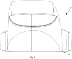
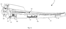
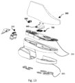
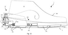
- footwear sole indicates an element configured to be associated with a footwear, in particular to the outer upper portion, for example to an upper 300, of a footwear 1.
- the sole 10 comprises a first layer 100 configured to be connected to an upper 300 of a footwear 1 to form an inner environment 11 of the footwear 1.
- Said inner environment 11 is the substantially closed space of the footwear 1 which space, in use, is apt to accommodate therein a user's foot.
- first layer 100 means the portion of sole 1 facing a user's foot and suitable, in use, to be placed in direct contact with the foot of that user.
- Said first layer 100 can therefore comprise only the portion of the sole located at the lying area of a user's foot, that is to say the inner sole or the footbed of a footwear 1, or it can also comprise the inner buttress, that is the portion apt to cover the user's calcaneus or heel.
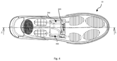
- the first layer 100 comprises a plurality of through orifices 101 or openings. Therefore, when the first layer 100 is coupled to an upper 300, said plurality of through orifices 101, or through holes, allow the communication with the inner environment of the footwear 11.
- said plurality of orifices 101 is made at a perimetric region, i.e. peripheral or edge region, of the first layer 100. Even more preferably said orifices 101 are made at the perimetric region of the insole or the footbed.
- the first layer 100 comprises a grid element provided with said plurality of orifices 101. Said grid element can be housed or inserted into a suitable seat consisting of a through opening of the first layer 100 placed or made at a heel region of said first layer 100; in particular, the grid element can be housed in the buttress or in the inner sole or the footbed of a footwear 1.
- the sole 10 further comprises a second layer 200 connected to the first layer 100.
- Said second layer 200 with respect to the first layer 100, is apt in use to face a walking surface S.
- the second layer 200 comprises a plurality of chambers 201. These chambers 201 constitute substantially hollow spaces within said second layer 200.
- one or more channels or passages 400 are also part of the sole 10, forming a fluid communication system, which fluidically connect said plurality of orifices 101 and said plurality of chambers 201 to each other. Put it differently, the multiple channels or passages 400 form a pneumatic path or circuit. It should also to be understood as a fluid communication system 400 wherein the fluid communication can be closed or interrupted even momentarily, as described below.
- the fluid communication system 400 is formed by the one or more channels or passages which extend between the plurality of orifices 101 and the plurality of chambers 201 to allow the fluid communication between them.
- a fluid such as air and/or water vapour
- the present disclosure only refers to the passage of air between said plurality of orifices 101 and said plurality of chambers 201.
- said one or more channels or passages 400 are also apt to connect each of the chambers of the plurality of chambers 201 together to at least one other chamber of the plurality of chambers 201. That is to say, the chambers 201 can in turn be interconnected and/or in fluid communication directly between them.
- the sole 10 comprises a pressurization device 500 connected to the one or more channels or passages 400 and configured to increase an air pressure in said plurality of chambers 201.
- the pressurization device 10 is apt to withdraw air through the plurality of orifices 101 and to supply such air to the plurality of chambers 201, increasing the pressure inside the latter ones.
- the pressurization device 500 is therefore to be understood as a supply device which conveys or supplies an air or fluid flow towards the plurality of chambers 201.
- the pressurization device 500 can be a device apt to suck the air within the plurality of chambers 201.
- the sole 10 further includes one or more regulating valves 600, in fluid communication with said one or more channels or passages 400.
- the one or more regulating valves 600 are i.e. connected or associated to the one or more channels or passages 400.
- Said one or more regulating valves 600 are configured to adjust a pressure within the plurality of chambers 201.
- the at least one regulating valve 600 is apt to regulate the air pressure inside the chambers 201. More precisely, the at least one regulating valve 600 is apt to adjust the air pressure inside the chambers 201 between a pressure equal to the atmospheric pressure and a pressure higher than the atmospheric pressure.
- the one or more regulating valves 600 are on-off valves or shut-off valves.
- the one or more regulating valves 600 are configured to keep the plurality of chambers 201 at a predefined minimum pressure, equal to atmospheric pressure, or at a predefined maximum pressure, higher than atmospheric pressure.
- the one or more regulating valves 600 do not allow a fine adjustment of the air pressure within the plurality of chambers 201 but are, instead, configured to allow a complete closing or opening of the fluid communication between the plurality of chambers 201 and the one or more channels or passages 400.
- the one or more regulating valves 600 should be understood in the context of the present disclosure as means for adjusting the amount of air present within each chamber of the plurality of chambers 201, and consequently to define the pressure inside each of them.
- the pressurization device 500 and said one or more regulating valves 600 are configured to control the air flow from said plurality of orifices 101 to said plurality of chambers 201 and vice versa, between a dynamic condition of ventilation and at least one static condition.
- the pressurization device 500 and said one or more regulating valves 600 are configured to control and adjust an air passage between said plurality of orifices 101 and said plurality of chambers 201 and vice versa. Therefore, when the sole 10 according to the present disclosure is associated with an upper 300, the pressurization device 500 and said one or more regulating valves 600 are apt to allow an exchange of air between the inner environment 11 of the footwear 1 and said plurality of chambers 201 and between said plurality of chambers 201 and the inner environment 11.
- said pressurization device 500 and said one or more regulating valves 600 are configured to determine a pressure imbalance between the pressure within the inner environment 11 of the footwear and the plurality of chambers 201 and to restore a pressure balance between the inner environment 11 of the footwear and the plurality of chambers 201.
- the pressurization device 500 and said one or more regulating valves 600 are apt to adjust said air passage or flow between a dynamic ventilation condition, i.e. a dynamic condition wherein there is an air flow inside the sole 1 between the plurality of orifices 101 and the plurality of chambers 201 or vice versa, and at least one static condition, wherein an air flow or an air exchange or an air passage is substantially lacking between the plurality of orifices 101 and the plurality of chambers 201 or vice versa.
- a dynamic ventilation condition i.e. a dynamic condition wherein there is an air flow inside the sole 1 between the plurality of orifices 101 and the plurality of chambers 201 or vice versa
- static condition wherein an air flow or an air exchange or an air passage is substantially lacking between the plurality of orifices 101 and the plurality of chambers 201 or vice versa.
- the pressurization device 500 and said one or more regulating valves 600 are configured to allow the passage or an air flow between said plurality of orifices 101 and said plurality of chambers 201 and vice versa; while, in said at least one static condition, the one or more regulating valves 600 are configured to prevent, or oppose or prevent or hinder, an air passage or flow between said plurality of chambers 201 and said plurality of orifices 101.
- the one or more regulating valves 600 in the dynamic ventilation condition, can be completely open to allow fluid communication between the plurality of chambers 201 and the plurality of orifices 101.
- the pressurization device 500 in the condition of reverse ventilation, is also configured to allow a return or passage of air from said plurality of chambers 201 to said plurality of orifices 101, or to not prevent such return.
- the one or more regulating valves 600 in the static condition, can be completely closed to prevent fluid communication between the plurality of chambers 201 and the plurality of orifices 101.
- the dynamic ventilation condition can be a direct ventilation condition or a reverse ventilation condition.
- the one or more regulating valves 600 are configured to allow the passage of air and the pressurization device 500 is configured to generate an air flow from the orifices 101 to the plurality of chambers 201.
- the pressurization device 500 is apt to suck or withdraw air through said plurality of orifices 101 and to supply it, through the communication system 400 and the one or more regulating valves 600, to the plurality of chambers 201.
- the pressurization device 500 is therefore configured to withdraw air from the inner environment of the footwear 11, at a pressure equal to the atmospheric pressure, and transferring it within said plurality of chambers 201, increasing the pressure of the air in the chambers 201.
- the pressurization device 500 and the one or more regulating valves 600 are configured to create or generate a pressure difference or imbalance between the pressure inside the plurality of chambers 201 and the atmospheric pressure; that is, an imbalance or a difference in pressure between the plurality of chambers 201 and the inner environment 11 of the footwear 1.
- said pressurization device 500 is configured to bring the air pressure inside the chambers up to a pressure of 1.5-4 bar, even more preferably up to a pressure of about 2.5 bar.
- the one or more regulating valves 600 are configured to allow a return of air from said plurality of chambers 201 to said plurality of orifices 101.
- the one or more regulating valves 600 are configured to allow a discharge or expulsion of the air from the plurality of chambers 201 towards the plurality of orifices 101.
- said discharged or said expulsion of air from the chambers 201 is a maximum or complete expulsion.
- the one or more regulating valves 600 are configured to allow a complete or maximum passage of air from said plurality of chambers 201 to said plurality of orifices 101.
- the pressurization device 500 in the reverse ventilation condition, is configured not to withdraw air through the plurality of orifices 101; that is, the pressurization device 500 is inactive.
- the pressurization device 500 in the condition of reverse ventilation, is also configured to allow a return or passage of air from said plurality of chambers 201 to said plurality of orifices 101, or to not prevent such a return. Therefore, in this indirect ventilation condition, the pressurization device 500 and the one or more regulating valves 600 are configured to restore the pressure balance between the pressure inside the plurality of chambers 201 and the atmospheric pressure; that is to say to take the pressure within the plurality of chambers 201 back to the pressure within the inner environment 11 of the footwear 1, i.e. at atmospheric pressure.
- the at least one static condition is a first static condition, wherein a fluid communication between the chambers 201 and the orifices 101 is lacking.
- the pressurization device 500 is configured not to withdraw air through the plurality of orifices 101; that is, the pressurization device 500 is inactive.
- Said one or more regulating valves 600 are configured to prevent a return of air from said plurality of chambers 201 to said plurality of orifices 101. That is to say that, in said first static condition, the air present within the plurality of chambers 201 cannot pass through the one or more channels or passages 400 to reach the plurality of orifices 101.
- a discharge or an escape of air from the plurality of chambers 201 to the plurality of orifices 101 is hindered or prevented.
- the chambers 201 keep the pressure, and said one or more regulating valves 600 are closed and cause an interruption of the fluid communication. Therefore, in said first static condition, an imbalance or a pressure difference is kept between the pressure inside the plurality of chambers 201 and the atmospheric pressure; that is, an imbalance or a pressure difference between the plurality of chambers 201 and the inner environment 11 of the footwear 1.
- the plurality of chambers 201 is either found or kept at a pressure higher than the atmospheric pressure.
- the plurality of chambers 201 is at a pressure of about 1.5-4 bar; even more preferably at a pressure of about 2.5 bar.
- the pressurization device 500 is configured not to withdraw air through the plurality of orifices 101; that is, the pressurization device 500 is inactive.
- a further static condition or second static condition.
- this second static condition there is a pressure balance between the plurality of chambers 201 and the atmospheric pressure; that is, the pressure within the chambers 201 equals the atmospheric pressure.
- the plurality of chambers 201 is at the same pressure as the inner environment 11 of the footwear.
- said one or more regulating valves 600 are configured to be fully open and cause complete fluid communication while the pressurization device 500 is configured not to withdraw air through the plurality of orifices 101; that is, the pressurization device 500 is inactive.
- the chambers 201 are therefore completely emptied.
- the plurality of chambers 201 are expandable chambers, or expansion chambers, apt to determine a determined configuration of the second layer 200.
- the increase in volume of the chambers caused by the air flow inside them, and the consequent pressure increase causes a deformation of the same second layer 200 such that a plurality of asperities, protrusions or bulges are present or formed, at each of said chambers 201.
- the plurality of chambers 201 in said first static condition, has a first volume v1 and while in said second static condition the plurality of chambers 201 has a second volume v2, smaller than said first volume v1.
- the plurality of chambers 201 in said first static condition, is in or reaches an inflated configuration, while in said second static condition the plurality of chambers 201 is in or reaches a deflated configuration.
- the first volume v1 can be reached when the pressure within the plurality of chambers 201 reaches a predefined maximum pressure and the volume v2 can be reached when the plurality of chambers 201 reaches the atmospheric pressure.
- Both the first volume v1 and the second volume v2 can be known in advance or can be calculated according to techniques known to a person skilled in the art, and consequently the average time necessary for the plurality of chambers 201 to pass from the first volume v1 to the second volume v2 and/or vice versa can be calculated.
- the sole 10 also has a support surface 203 apt, in use, to be placed towards, or placed in contact with, a walking surface S.
- Said support surface 203 is therefore a surface, which in use it is opposite the surface the user's foot is in contact with.
- the second layer 200 defines at least part of said support surface 203 or is capable of causing a change in the morphology or shape of said support surface 203.
- the second layer 200 is the layer of the sole 10 which rests on the ground, or it is part of or is partially integrated in a third layer 800 of the sole which rests on the ground.
- the supporting surface 203 is formed integrally by the second layer 200, or it is formed in part by said second layer 200 and by said third layer 800.
- the second layer 200 is covered by the third layer 800; which defines said support surface 203.
- said support surface 203 is substantially flattened or flat. That is to say that when the chambers 201 are not under pressure, i.e. they are at a pressure equal to the atmospheric pressure, said chambers 201 determine an almost flattened or flat conformation of the supporting surface 203.
- the surface of support 203 has or forms an asperity or protuberance or bulges at each chamber of said plurality of chambers 201. In other words, when the chambers 201 are under pressure, i.e. they are at a pressure higher than atmospheric pressure, said chambers 201 determine a three-dimensional conformation of the support surface 203.
- said asperities or protuberances or bulges protrude in a direction facing the walking surface S.
- the asperities or protuberances or bulges, in use protrude towards said walking surface S.
- the asperities or protuberances or bulges substantially form studs on the bearing surface 203.
- the chambers 201 are made at a first end region of the second layer 200 and a second end region of the second layer 200, opposite to said first end region.
- the chambers 201 are distributed at a first end region of the sole 10 and a second end region of the sole 10.
- said first end region and said second end region of the sole 10, and consequently the second layer 200 correspond to a heel region and a toe region.
- the chambers of the plurality of chambers 201 can be made at a central region of the sole 10 and a peripheral region of the sole 10, which surrounds said central region.
- said one or more regulating valves 600 comprise a first valve 601 and a second valve 602, configured to allow or prevent the fluid communication between the plurality of orifices 101 and each chamber 201 of the plurality of chambers respectively in the first end region of the sole 10 and in the second end region of the sole 10 via the aforementioned fluid communication system 400. Therefore, the first valve 601 is configured to allow or not the fluid communication with a first compartment or group of chambers 201, while the second valve is configured to allow or not fluid communication with a second compartment or group of chambers 201. In other words, the first valve 601 adjusts the pressure within the chambers located in the first end region and, likewise, the second valve 602 adjusts the pressure within the chambers located in the second end region. It follows that it is possible to activate or operate the first valve 601 and the second valve 602 separately or separately; in this way it is possible to create a difference in the dynamic or static condition of ventilation between said two groups of chambers 201.
- the pressurization device 500 and/or the one or more regulating valve 600 are mechanical members that can be activated manually by a user.
- the pressurization device 500 and/or the one or more regulating valve 600 are electronic devices.
- both the pressurization device 500 and the one or more regulating valve 600 are electronic devices.
- pressurization devices 500 are: volumetric compressors, rotary compressors, peristaltic pumps, electromechanical pumps, manual pumps.
- regulating valves 600 are: solenoid valves, such as electronically controlled pinch valves or electronically controlled duckbill valves.
- the sole 10 comprises a time switch or timer (not shown in the figures) connected to the one or more regulating valves 600 and/or to the pressurization device 500.
- the timer is configured or programmed to control the opening/closing of the one or more regulating valves 600 at predetermined time intervals; alternatively or in combination with this aspect, the time switch or timer is configured or programmed to control the activation of the pressurization device 500 at predetermined time intervals.
- the time switch or timer can be mechanical, electrical or electronic.
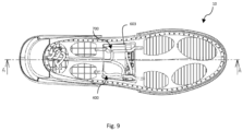
- the sole 10 comprises a control unit 700.
- the control unit is connected to the one or more regulating valve 600 and is configured or programmed to control the closing and/or opening of said valves.
- control unit 700 is connected to the pressurization device 500 and is apt to control the activation of the latter.
- the pressurization device 500 is activated according to a command sent to it by the control unit 700.
- the control unit 700 can also be configured or programmed to activate or deactivate the pressurization device 500.
- the control unit 700 is, for example, apt to interrupt the operation of the pressurization device 500 upon reaching a threshold pressure within the plurality of chambers 201.
- control unit 700 can comprise a time switch or timer for controlling the opening/closing of the at least one regulating valve 600 and/or the activation of the pressurization device 500 at predefined or predetermined time intervals. These time intervals are preferably fixed or regular or of the same duration. In this way, by means of the time switch or timer, the plurality of chambers 201 can be discharged at regular time intervals. As said above, knowing, for example, the average amount of time necessary for the chambers 201 to reach the first volume v1, the plurality of chambers 201 can therefore be discharged regularly upon reaching this first volume v1. Further or alternatively, the fluid communication with the plurality of chambers 201 can be closed at regular time intervals.
- the flow of further air to the plurality of chambers 201 can be prevented, thus avoiding the achievement of a volume greater than the first volume v1.
- the sole 10 also comprises a pressure sensor 603, apt to detect a pressure within the plurality of chambers 201.
- said pressure sensor 603 is connected to the control unit.
- the control unit 700 is configured or programmed to control the closing and/or opening of said one or more regulating valves 600 if the pressure detected by the pressure sensor 603 reaches a certain pressure threshold. That is to say that the control unit 700 is configured to control the activation of one or more regulating valves 600 according to the reaching of a certain threshold or pressure limit within the chambers 201.
- the sole 10 comprises a first pressure sensor and a second pressure sensor, respectively apt to detect a pressure within a first group of chambers and within a second group of chambers 201 and connected to the control unit 700.
- the fluid communication with the first group of chambers 201 and with the second group of chambers 201 is open or closed depending on the state of a first regulating valve and a second regulating valve respectively.
- the control unit 700 is configured or programmed to control the closing or opening of said first regulating valve 601 if the pressure detected by the first pressure sensor reaches a certain pressure threshold and, similarly, the control unit 700 is configured or programmed to control the closing or opening of said second regulating valve if the pressure detected by the second pressure sensor reaches a certain pressure threshold. That is, the control unit 700 is configured to separately or selectively control the activation of the first regulating valve and the second regulating valve according to the reaching of a certain threshold or pressure limit within the first group of chambers 201 and within the second group of chambers 201.
- said pressure sensor 603, is a pressure switch.
- said pressure threshold is equal to about 1.5-4 bar, even more preferably about 2.5 bar. This pressure threshold can correspond to the aforementioned predefined maximum pressure.
- the pressurizing device 500 is positioned at an end region of the sole 10, such as for example a heel region. In this way, the pressurization device 500 is less of a hindrance when walking or performing other activities and, if its activation is manual, it is also easily accessible for a user.
- the pressurization device 500 is positioned at a region of the waist edge of the sole 10.
- the at least one pressure sensor 603 and the control unit 700 are housed within the second layer 200.
- the second layer 200 can therefore comprise a housing or seat for the pressure sensor 603 and for the control unit 700. Even more preferably, the control unit 700 is located in a waist edge region of the second layer 200.
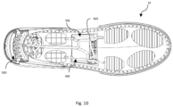
- the sole 10 comprises a further layer.
- Said further layer is a third layer 800, coupled to the second layer 200 of the latter.
- the third layer 800 covers at least partially the second layer 200 and forms completely or partially the resting surface 203 of the sole 10.
- said pressurization device 500 is housed within the third layer 800.
- said third layer 800 has a housing for the pressurization device 500 at an end region.
- the pressurization device 500 is contained in a housing of the third layer 800 made in a heel region or buttress region of the sole 10.
- the sole 10 further comprises a temperature sensor and/or a humidity sensor.
- Said temperature sensor and/or the humidity sensor are associated with the first layer 100.
- the temperature sensor and/or the humidity sensor in operation, are therefore apt respectively to detect or measure the temperature and humidity of the inner environment 11 of the footwear 1.
- Said temperature sensor and/or a humidity sensor are connected to the control unit 700.
- the control unit 700 is programmed or configured to activate the pressurization device 500 upon reaching a certain temperature and/or humidity threshold.
- control unit 700 is programmed or configured to activate the pressurization device if a certain temperature and humidity value and/or a threshold is reached within the inner environment 11 of the footwear 1.
- the control unit 700 can be connected to the at least one regulating valve 600 and be configured so as to control the opening or closing of the latter one/ones depending on the temperature and/or humidity reached within the inner environment 11.
- the control unit 700 can be configured to open or close the at least one regulating valve 600 once the aforementioned temperature and/or humidity threshold has been reached within inner environment 11.
- the control unit 700 can be configured to allow or not a fluid communication between the plurality of chambers 201 and the plurality of orifices 101 depending on the temperature and/or humidity in the inner environment 11.
- the present disclosure also relates to a footwear 1 comprising a sole 10 according to one or more of the aspects described up to here.
- the footwear 1 also comprises an upper 300 associated with the first layer 100 of the sole 10 so as to define an inner environment 11 of the footwear 10.
- the footwear 1 comprises a temperature sensor and/or a humidity sensor coupled to the upper 300.
- the temperature sensor and/or the humidity sensor are configured to detect or measure, respectively, the temperature and humidity within the inner environment 11 of the footwear 1.
- the temperature sensor and/or the sensor are therefore connected to the control unit 700.
- the latter 700 is also configured to control the operation, in particular to determine the activation, of the pressurization device 500. More specifically, the control unit 700 is configured or programmed to determine or control the activation of the pressurization device 500 upon reaching a certain, i.e. predefined, temperature threshold and/or a certain s oglia of humidity. Preferably, moreover, the control unit 700 can also be connected to the at least one regulating valve 600 and be configured so as to control the opening or closing of the latter depending on temperature and/or humidity detected by the temperature sensor or by the humidity sensor respectively. In particular, the control unit 700 can be configured to open or close the at least one regulating valve 600 once the aforementioned temperature and/or humidity threshold within the inner environment 11 is reached.
- a further subject matter of the present disclosure has as a method for ventilating the inner environment of a footwear.
- the method for ventilating the inner environment 11 of a footwear 1 comprises a step of preparing an upper 300, preparing a first layer 100 of sole 10, having a plurality of through orifices 101, and applying or associating or connecting said first layer 100 to said upper to form the inner environment 11.
- the method according to the present disclosure provides for providing a second layer 200 of sole 10, comprising a plurality of chambers 201 and coupling said second layer 200 to said first layer 100.
- said second layer 200 is coupled to the first layer 100 on the opposite side with respect to the upper 300.
- the method further provides fluidically connecting said plurality of orifices 101 and said plurality of chambers 201 through one or more several channels or passages 400 between said plurality of orifices 101 and said plurality of chambers 201.
- the method provides for the making a system of fluid communication between the plurality of orifices 101 and the plurality of chambers 201.
- the method further provides providing a pressurizing device 500, put said pressurizing device 500 in fluid communication with said one or more channels or passages 400, providing a or more regulating valves 600 and put said one or more regulating valves 600 in fluid communication with said one or more channels or passages 400.
- the method provides for generating and adjusting an air passage or flow between said plurality of orifices 101 and said plurality of chambers 201 and vice versa. That is to say that according to the aforesaid method it is created an air flow which flows, or passes, in a first direction between the plurality of orifices 101 and the plurality of chambers 201 or in a second direction, opposite to the first direction, between the plurality of chambers 201 and the plurality of orifices 101.
- it is generated and adjusted an air flow moving away from or exiting the inner environment 11 of the footwear 1, while in the second case an air flow is created and adjusted entering the inner environment 11 of the footwear.
- a direct ventilation condition is created while in the second case a reverse ventilation condition is created.
- the step creating an air passage or flow between said plurality of orifices 101 and said plurality of chambers 201 or vice versa comprises: sucking air through said plurality of orifices 101 by means of said pressurization device 500, supplying said air through said one or more channels or passages 400 and said one or more regulating valves 600 to the plurality of chambers 201, increasing the air pressure within said plurality of chambers 201, preventing a return of air through said one or more regulating valves 600, allowing a return or passage of air through said one or more regulating valves 600 towards the plurality of orifices 101.
- the generation of an air flow comprises sucking a certain amount of air from the inner environment of the footwear, by means of the pressurization device 500, supply said quantity of air to the plurality of chambers 201 until an increase in the pressure of air within the chambers 201 is obtained and blocking, by means of the at least one regulating valve 600, the fluid communication between the plurality of chambers 201 and the plurality of orifices 101 and thus allowing the fluid communication between the plurality of chambers 201 and the plurality of orifices 101.
- an air flow is generated in the direction between the plurality of orifices 101, hence the inner environment of the footwear, and said plurality of chambers 201.
- an air flow is generated, in the direction between the plurality of chambers 201 and the plurality of orifices 101.
- the return or passage of air through said one or more regulating valves 600 is a complete or maximum passage of air from said plurality of chambers 201 to said plurality of orifices 101.
- the plurality of chambers 201 empties completely.
- the one or more regulating valves 600 are completely open to allow complete venting or deflation of the plurality of chambers.
- the method further comprises the steps of: measuring the time, opening and/or closing the at least one regulating valve 600 at predetermined time intervals and/or controlling the activation of the device of pressurization 500 at pre-established time intervals.
- the method may provide that after a predetermined time period, the one or more regulating valves 600 are open or closed and/or that the pressurization device 500 is activated or deactivated.
- the predetermined time interval can be equal to the time required for the plurality of chambers 201 to reach a predefined or predetermined maximum pressure or a predefined or predetermined maximum volume.
- the method further comprises the steps of: detecting a pressure within the plurality of chambers 201, defining a pressure threshold, controlling the closing and/or opening of the at least one regulating valve 600 if the detected pressure reaches this specific pressure threshold.
- the method can also comprise the step of controlling the activation of the pressurization device 500 depending on the measured pressure.
- this phase may include the activation or deactivation of the pressurization device 500 upon reaching the aforementioned pressure threshold.
- the method involves measuring or monitoring the pressure within the plurality of chambers 201 and adjusting the air flow and humidity to/from the latter.
- the method further comprises the steps of: detecting the temperature and/or humidity within the inner environment 11 of the footwear, defining a temperature and/or humidity threshold, controlling the activation of the pressurization device 500 and/or open or close the at least one regulating valve 600 upon reaching a predetermined temperature and/or humidity threshold.
- the method involves measuring or monitoring the temperature and/or humidity within the inner environment 11 and adjusting the air flow and humidity to/from the plurality of chambers 201.
Landscapes
- Health & Medical Sciences (AREA)
- Epidemiology (AREA)
- General Health & Medical Sciences (AREA)
- Public Health (AREA)
- Engineering & Computer Science (AREA)
- Microelectronics & Electronic Packaging (AREA)
- Chemical & Material Sciences (AREA)
- Materials Engineering (AREA)
- Footwear And Its Accessory, Manufacturing Method And Apparatuses (AREA)
Claims (22)
- Sohle (10) für Schuhwerk (1), umfassend:- eine erste Lage (100) mit einer Mehrzahl von Durchgangsöffnungen (101), die dazu ausgelegt ist, mit einem Obermaterial (300) des Schuhwerks (1) verbunden zu sein und einen Innenraum (11) des Schuhwerks (1) zu bilden;- eine zweite Lage (200), die mit der besagten ersten Lage (100) gekoppelt ist und eine Mehrzahl von Kammern (201) aufweist;- ein oder mehrere Kanäle oder Passagen (400), welche die besagte Mehrzahl von Öffnungen (101) und die besagte Mehrzahl von Kammern (201) strömungsmäßig miteinander verbinden;- eine Vorrichtung (500) zur Druckbeaufschlagung in strömungsmäßiger Verbindung mit den besagten ein oder mehreren Kanälen oder Passagen (400), welche dazu ausgelegt ist, einen Luftdruck in der besagten Mehrzahl von Kammern (201) zu erhöhen;dadurch gekennzeichnet, dass die besagte Sohle (10) ein oder mehrere Regelventile (600) umfasst, die in einer strömungsmäßigen Verbindung mit den besagten ein oder mehreren Kanälen oder Passagen (400) stehen und dazu ausgelegt sind, einen Druck in der besagten Mehrzahl von Kammern (201) einzustellen.
- Sohle (10) gemäß Anspruch 1, wobei die besagte Vorrichtung (500) zur Druckbeaufschlagung und die besagten ein oder mehreren Regelventile (600) dazu ausgelegt sind, um den Luftstrom von der besagten Mehrzahl von Öffnungen (101) zu der besagten Mehrzahl von Kammern (201) und umgekehrt zu steuern, zwischen einem dynamischen Belüftungszustand und wenigstens einem statischen Zustand;und wobei in dem besagten dynamischen Belüftungszustand die besagte Vorrichtung (500) zur Druckbeaufschlagung und die besagten ein oder mehreren Regelventile (600) dazu ausgelegt sind, um den Luftstrom zwischen der besagten Mehrzahl von Kammern (201) und der besagen Mehrzahl von Öffnungen (101), und umgekehrt, zu erlauben;und wobei in dem besagten wenigstens einen statischen Zustand die besagten ein oder mehreren Regelventile (600) dazu ausgelegt sind, einen Luftstrom zwischen der besagten Mehrzahl von Kammern (201) und der besagten Mehrzahl von Öffnungen (101) zu unterbinden oder zu hemmen.
- Sohle (10) gemäß Anspruch 2, wobei der besagte dynamische Zustand ein direkter Belüftungszustand sein kann oder ein gegenläufiger Belüftungszustand; wobei in dem besagten direkten Belüftungszustand die besagte Vorrichtung (500) zur Druckbeaufschlagung dazu ausgelegt ist, um Luft durch die besagte Mehrzahl von Öffnungen (101) einzusaugen und sie zu der Mehrzahl von Kammern (201) zu leiten, und wobei die besagten ein oder mehreren Regelventile (600) dazu ausgelegt sind, um den Luftstrom von der besagten Mehrzahl von Öffnungen (101) zu der besagten Mehrzahl von Kammern (201) zu erlauben;
und wobei in dem besagten gegenläufigen Belüftungszustand die besagten ein oder mehreren Regelventile (600) dazu ausgelegt sind, um einen Rückstrom von Luft von der besagten Mehrzahl von Kammern (201) zu der besagten Mehrzahl von Öffnungen (101) zuzulassen. - Sohle (10) gemäß Anspruch 3, wobei in dem besagten gegenläufigen Belüftungszustand die besagten ein oder mehreren Regelventile (600) dazu ausgelegt sind, um einen vollen oder maximalen Luftstrom von der besagten Mehrzahl von Kammern (201) zu der besagten Mehrzahl von Öffnungen (101) zuzulassen.
- Sohle (10) gemäß einem der Ansprüche 2 bis 4, wobei es in dem besagten statischen Zustand einen ersten statischen Zustand gibt; und wobei in dem besagten ersten statischen Zustand der Druck innerhalb der Mehrzahl von Kammern (201) größer ist als der Atmosphärendruck; und wobei die besagte Vorrichtung (500) zur Druckbeaufschlagung und die besagten ein oder mehreren Regelventile (600) dazu ausgelegt sind, um den Luftstrom von der besagten Mehrzahl von Öffnungen (101) zu der besagten Mehrzahl von Kammern (201), und umgekehrt, zu steuern, zwischen einem dynamischen Belüftungszustand und einem zweiten statischen Zustand, wobei in dem besagten zweiten statischen Zustand der Druck innerhalb der Mehrzahl von Kammern (201) substantiell gleich dem Atmosphärendruck ist.
- Sohle (10) gemäß Anspruch 5, wobei in dem besagten ersten statischen Zustand die Mehrzahl von Kammern (201) ein erstes Volumen (v1) aufweist, und wobei in dem besagten zweiten statischen Zustand die Mehrzahl von Kammern (201) ein zweites Volumen (v2) aufweist, das kleiner ist als das besagte erste Volumen (v1).
- Sohle (10) gemäß Anspruch 6 mit einer Stützfläche (203), die geeignet ist, beim Gebrauch in Richtung einer Lauffläche (S) zu zeigen oder in Kontakt mit jener platziert zu werden, wobei die besagte zweite Lage (200) wenigstens einen Teil der besagten Stützfläche (203) bildet, und wobei in dem besagten zweiten statischen Zustand die besagte Stützfläche (203) substantiell flach ist, und wobei in dem besagten ersten statischen Zustand die besagte Stützfläche (203) an jeder Kammer der besagten Mehrzahl von Kammern (201) eine Ausbuchtung aufweist oder formt, die beim Gebrauch in Richtung zu der besagten Lauffläche (S) hervorsteht.
- Sohle (10) gemäß einem der vorhergehenden Ansprüche, wobei die Kammern der besagten Mehrzahl von Kammern (201) über einen ersten Endbereich der Sohle (10) und über einen zweiten Endbereich der Sohle (10) verteilt sind, und wobei die besagten ein oder mehreren Regelventile (600) ein erstes Ventil (601) umfassen, das dazu ausgelegt ist, um die Strömungsverbindung zwischen den besagten ein oder mehreren Kanälen oder Passagen (400) und jeder Kammer (201) von der Mehrzahl von Kammern in dem ersten Endbereich der Sohle (10) zu öffnen oder zu schließen, sowie ein zweites Ventil (602), welches dazu ausgelegt ist, die Strömungsverbindung zwischen einem oder mehreren Kanälen oder Passagen (400) und jeder Kammer (201) von der Mehrzahl der Kammern im zweiten Endbereich der Sohle (10) zu öffnen oder zu schließen.
- Sohle (10) gemäß einem der vorhergehenden Ansprüche, umfassend einen Zeitmesser, der an einem oder mehreren Regelventilen (600) und/oder an der besagten Vorrichtung (500) zur Druckbeaufschlagung angeschlossen ist, und wobei der besagte Zeitmesser dazu ausgelegt oder programmiert ist, um das Öffnen / Schließen der besagten ein oder mehreren Regelventile (600) in vorher festgelegten Zeitintervallen zu steuern, und/oder um die Aktivierung der besagten Vorrichtung (500) zur Druckbeaufschlagung in vorher festgelegten Zeitintervallen zu steuern.
- Sohle (10) gemäß einem der Ansprüche von 1 bis 8, umfassend einen Drucksensor (603), der dazu geeignet ist, einen Druck innerhalb der Mehrzahl von Kammern (201) zu messen, sowie eine Steuereinheit (700), die an dem besagten Drucksensor (603) und an den besagten ein oder mehreren Regelventilen (600) angeschlossen ist, und wobei die besagte Steuereinheit (700) dazu ausgelegt oder programmiert ist, um das Schließen und/oder Öffnen des besagten wenigstens einen Regelventils (600) zu steuern, wenn der von dem Drucksensor (603) gemessene Druck einen bestimmten Druckschwellwert erreicht.
- Sohle (10) gemäß Anspruch 10, wobei die besagte Steuereinheit (700) an der besagten Vorrichtung (500) zur Druckbeaufschlagung angeschlossen ist und dazu ausgelegt oder programmiert ist, um die Aktivierung der besagten Vorrichtung (500) zur Druckbeaufschlagung zu steuern.
- Sohle (10) gemäß einem der vorhergehenden Ansprüche, wobei die besagte Vorrichtung (500) zur Druckbeaufschlagung an einem Endbereich der Sohle (10) angeordnet ist.
- Sohle (10) gemäß Anspruch 10 und 11, umfassend einen Temperatursensor (901) und/oder einen Feuchtigkeitssensor (902), der besagten ersten Lage (100) zugeordnet und dazu geeignet, um beim Gebrauch die Temperatur beziehungsweise die Feuchtigkeit in dem Innenraum (11) zu messen, wobei der besagte Temperatursensor (901) und/oder der besagte Feuchtigkeitssensor (902) an der Steuereinheit (700) angeschlossen ist, und wobei die Steuereinheit (700) dazu programmiert oder ausgelegt ist, um die Vorrichtung (500) zur Druckbeaufschlagung nach Erreichen eines bestimmten Temperatur- oder Feuchtigkeitsschwellwertes zu aktivieren.
- Schuhwerk (1), das eine Sohle (10) für ein Schuhwerk gemäß einem der Ansprüche 1 bis 13 aufweist sowie ein Oberteil (300), wobei die besagte Sohle (10) und das besagte Oberteil (300) den besagten Innenraum (11) des Schuhwerks (1) umgrenzen.
- Schuhwerk (1), umfassend eine Sohle (10) für ein Schuhwerk gemäß den Ansprüchen 10 und 11 sowie ein Oberteil (300), wobei die besagte Sohle (10) und das besagte Oberteil (300) einen Innenraum (11) des Schuhwerks (1) umgrenzen, der beim Gebrauch dazu geeignet ist, den Fuß eines Benutzers aufzunehmen, und wobei das besagte Schuhwerk (1) ferner einen Temperatursensor (901) aufweist und/oder einen Feuchtigkeitssensor (902), der dem besagten Oberteil (300) zugeordnet ist sowie dazu geeignet ist, die Temperatur beziehungsweise die Feuchtigkeit innerhalb des Innenraums (11) zu messen, und wobei der besagte Temperatursensor (901) und/oder der besagte Feuchtigkeitssensor (902) an der Steuereinheit (700) angeschlossen ist, und wobei die Steuereinheit (700) dazu programmiert oder ausgelegt ist, um die Vorrichtung (500) zur Druckbeaufschlagung beim Erreichen eines bestimmten Temperatur- oder Feuchtigkeitsschwellwertes in dem besagten Innenraum zu aktivieren.
- Verfahren zur Belüftung des Innenraums (11) eines Schuhwerks (1), wobei das besagte Verfahren die folgenden Schritte aufweist:- Bereitstellen eines Oberteils (300),- Anordnen einer ersten Lage (100) der Sohle (10), die eine Mehrzahl von Durchgangsöffnungen (101) aufweist,- Verbinden der besagten ersten Lage der Sohle (10) mit dem besagten Oberteil (300), um einen Innenraum (11) zu bilden,- Bereitstellen einer zweiten Lage (200) der Sohle (10), die eine Mehrzahl von Kammern (201) aufweist,- Koppeln der besagten zweiten Lage (200) an die besagte erste Lage (100),- strömungsmäßiges Verbinden der besagten Mehrzahl von Öffnungen (101) und der besagten Mehrzahl von Kammern (201) durch einen oder mehrere Kanäle oder Passagen (400) zwischen der besagten Mehrzahl von Öffnungen (101) und der besagten Mehrzahl von Kammern (201),- Bereitstellen einer Vorrichtung (500) zur Druckbeaufschlagung,- strömungsmäßiges Verbinden der besagten Vorrichtung (500) zur Druckbeaufschlagung mit den besagten ein oder mehreren Kanälen oder Passagen (400),wobei das besagte Verfahren durch die folgenden Schritte gekennzeichnet ist:- Bereitstellen eines oder mehrerer Regelventile (600),- strömungsmäßiges Verbinden der besagten ein oder mehreren Regelventile (600) mit den besagten ein oder mehreren Kanälen oder Passagen (400),- Erzeugen und Einstellen eines Luftdurchgangs oder -stroms zwischen der besagten Mehrzahl von Öffnungen (101) und der besagten Mehrzahl von Kammern (201), oder umgekehrt.
- Verfahren gemäß Anspruch 16, wobei der besagte Schritt des Einstellens oder Steuerns eines Luftdurchgangs oder -stroms zwischen der besagten Mehrzahl von Öffnungen (101) und der besagten Mehrzahl von Kammern (201) umfasst:- Saugen von Luft durch die besagte Mehrzahl von Öffnungen (101) mittels der besagten Vorrichtung (500) zur Druckbeaufschlagung,- Leiten der besagten Luft durch die besagten ein oder mehreren Kanäle oder Passagen (400) und durch die besagten ein oder mehreren Regelventile (500) zu der Mehrzahl von Kammern (201),- Steigern des Luftdrucks innerhalb der besagten Mehrzahl von Kammern (201),- Unterbinden eines Rückstroms von Luft durch die besagten ein oder mehreren Regelventile (600),- Zulassen eines Rückstroms oder eines Durchgangs von Luft durch die besagten ein oder mehreren Regelventile (600) in Richtung zu der Mehrzahl von Öffnungen (101).
- Verfahren gemäß Anspruch 17, wobei in dem besagten Schritt des Zulassens eines Rückstroms oder Durchgangs von Luft durch die besagten ein oder mehreren Regelventile (60) der Rückstrom oder Durchgang ein vollständiger oder maximaler Durchgang von Luft aus der besagten Mehrzahl von Kammern (201) zu der besagten Mehrzahl von Öffnungen (101) ist.
- Verfahren gemäß einem der vorhergehenden Ansprüche von 16 bis 18, ferner umfassend die folgenden Schritte: Messen der Zeit, Öffnen und/oder Schließen der besagten ein oder mehreren Regelventile (600) in vorbestimmten Zeitintervallen und/oder Steuern der Aktivierung der besagten Vorrichtung (500) zur Druckbeaufschlagung in vorbestimmten Zeitintervallen.
- Verfahren gemäß einem der vorhergehenden Ansprüche von 16 bis 18, ferner umfassend die folgenden Schritte: Erfassen eines Druckes innerhalb der besagten Mehrzahl von Kammern (201), Festlegen eines Druckschwellwertes, Steuern des Schließens und/oder Öffnens der besagten ein oder mehreren Regelventile (600), wenn der erfasste Druck diesen spezifischen Druckschwellwert erreicht.
- Verfahren gemäß dem vorhergehenden Anspruch, umfassend den Schritt des Steuerns der Aktivierung der besagten Vorrichtung (500) zur Druckbeaufschlagung als Funktion des gemessenen Drucks.
- Verfahren gemäß einem der vorhergehenden Ansprüche von 16 bis 18, ferner umfassend die folgenden Schritte: Erfassen der Temperatur und/oder Feuchtigkeit innerhalb des besagten Innenraums (11), Festlegen eines Temperatur- und/oder Feuchtigkeitsschwellwertes, Steuern der Aktivierung der besagten Vorrichtung (500) zur Druckbeaufschlagung und/oder Öffnen oder Schließen der besagten ein oder mehreren Regelventile (600) beim Erreichen des vorgegebenen Temperatur- und/oder Feuchtigkeitsschwellwertes.
Applications Claiming Priority (2)
| Application Number | Priority Date | Filing Date | Title |
|---|---|---|---|
| IT102020000000055A IT202000000055A1 (it) | 2020-01-03 | 2020-01-03 | Suola ventilata per calzatura |
| PCT/IB2020/062394 WO2021137114A1 (en) | 2020-01-03 | 2020-12-23 | Ventilated shoesole |
Publications (3)
| Publication Number | Publication Date |
|---|---|
| EP4084643A1 EP4084643A1 (de) | 2022-11-09 |
| EP4084643B1 true EP4084643B1 (de) | 2023-11-15 |
| EP4084643C0 EP4084643C0 (de) | 2023-11-15 |
Family
ID=70295685
Family Applications (1)
| Application Number | Title | Priority Date | Filing Date |
|---|---|---|---|
| EP20842729.4A Active EP4084643B1 (de) | 2020-01-03 | 2020-12-23 | Belüftete schuhsohle |
Country Status (6)
| Country | Link |
|---|---|
| US (1) | US12167772B2 (de) |
| EP (1) | EP4084643B1 (de) |
| JP (1) | JP7573036B2 (de) |
| CN (1) | CN115443084A (de) |
| IT (1) | IT202000000055A1 (de) |
| WO (1) | WO2021137114A1 (de) |
Families Citing this family (2)
| Publication number | Priority date | Publication date | Assignee | Title |
|---|---|---|---|---|
| US11819088B2 (en) * | 2021-08-09 | 2023-11-21 | Puma SE | Outsole pattern for an article of footwear |
| US12490809B2 (en) * | 2023-08-30 | 2025-12-09 | GD Stride LTD | Multi-chamber user device |
Family Cites Families (19)
| Publication number | Priority date | Publication date | Assignee | Title |
|---|---|---|---|---|
| WO1990009115A1 (en) * | 1989-02-08 | 1990-08-23 | Reebok International Ltd. | An article of footwear |
| US5860225A (en) * | 1993-04-16 | 1999-01-19 | Breeze Technology | Self-ventilating footwear |
| US5813142A (en) * | 1996-02-09 | 1998-09-29 | Demon; Ronald S. | Shoe sole with an adjustable support pattern |
| JPH1085008A (ja) | 1996-09-12 | 1998-04-07 | Repaado Corp | 排気装置が設置された安全靴とその製造装置及び製造方法 |
| AU2003279268A1 (en) * | 2002-10-11 | 2004-05-13 | Jeffrey S. Brooks, Inc. | Footwear with breathable sole |
| JP3122264U (ja) | 2006-03-27 | 2006-06-08 | 枝芳 羅 | 靴のエアクッション装置 |
| DE102007050593B4 (de) | 2007-10-23 | 2017-10-05 | Adidas International Marketing B.V. | Aktiv belüfteter Schuh |
| US20100005687A1 (en) * | 2008-07-11 | 2010-01-14 | Immobiliare Ramadoro S.R.L. | Shoe sole with forced ventilation |
| US8146268B2 (en) * | 2009-01-28 | 2012-04-03 | Sears Brands, Llc | Shoe having an air cushioning system |
| US20130213144A1 (en) | 2012-02-22 | 2013-08-22 | Nike, Inc. | Footwear Having Sensor System |
| TWI533815B (zh) | 2012-10-30 | 2016-05-21 | Manual and automatic pressure control of the shoe cushion | |
| US10178891B2 (en) * | 2013-03-22 | 2019-01-15 | Reebok International Limited | Sole and article of footwear having a pod assembly |
| KR20140131622A (ko) * | 2013-05-06 | 2014-11-14 | 김건수 | 통풍과 온열 기능이 구비된 신발 |
| CZ20131077A3 (cs) * | 2013-12-30 | 2015-07-22 | Oto Mušálek | Obuv s pneumatickou podešví |
| CN203723523U (zh) | 2014-01-16 | 2014-07-23 | 浙江工贸职业技术学院 | 一种透气鞋底 |
| DE202015103131U1 (de) * | 2015-06-15 | 2015-06-30 | Atmos Airwalk Ag | Schuh mit elektrischer Ventilationseinrichtung |
| CN105394872B (zh) * | 2015-12-17 | 2017-02-22 | 湖南师范大学 | 运动鞋 |
| EP3202275B1 (de) * | 2016-02-08 | 2019-03-13 | ATMOS airwalk ag | Schuh mit luftpumpeinrichtung und luftpolstern |
| WO2019050628A1 (en) * | 2017-09-11 | 2019-03-14 | Alexander Litvinov | VENTILATION APPARATUS FOR SHOES |
-
2020
- 2020-01-03 IT IT102020000000055A patent/IT202000000055A1/it unknown
- 2020-12-23 US US17/790,345 patent/US12167772B2/en active Active
- 2020-12-23 EP EP20842729.4A patent/EP4084643B1/de active Active
- 2020-12-23 WO PCT/IB2020/062394 patent/WO2021137114A1/en not_active Ceased
- 2020-12-23 JP JP2022540988A patent/JP7573036B2/ja active Active
- 2020-12-23 CN CN202080098013.0A patent/CN115443084A/zh active Pending
Also Published As
| Publication number | Publication date |
|---|---|
| WO2021137114A1 (en) | 2021-07-08 |
| CN115443084A (zh) | 2022-12-06 |
| JP2023508601A (ja) | 2023-03-02 |
| JP7573036B2 (ja) | 2024-10-24 |
| US20230055680A1 (en) | 2023-02-23 |
| IT202000000055A1 (it) | 2021-07-03 |
| EP4084643A1 (de) | 2022-11-09 |
| EP4084643C0 (de) | 2023-11-15 |
| US12167772B2 (en) | 2024-12-17 |
Similar Documents
| Publication | Publication Date | Title |
|---|---|---|
| US4991317A (en) | Inflatable sole lining for shoes and boots | |
| US4995173A (en) | High tech footwear | |
| US6553690B2 (en) | Ventilated footwear | |
| US6430843B1 (en) | Dynamically-controlled cushioning system for an article of footwear | |
| US6976321B1 (en) | Adjustable air cushion insole with additional upper chamber | |
| US6510624B1 (en) | Inflatable lining for footwear with protective and comfortable coatings or surrounds | |
| US5996250A (en) | Air-cooled shoe having an air exhaust pump | |
| US5025575A (en) | Inflatable sole lining for shoes and boots | |
| US6014823A (en) | Inflatable sole lining for shoes and boots | |
| US7451555B1 (en) | Methods of making adjustable air cushion insoles and resulting products | |
| EP4084643B1 (de) | Belüftete schuhsohle | |
| US20050217140A1 (en) | Shoe, adjustable, transpiring and cushioning | |
| EP1882421A2 (de) | Belüftungssystem und Vorrichtung für Schuhe | |
| WO2007032037A1 (en) | Aeration system and device for shoes | |
| AU8062891A (en) | Inflatable lining for footwear | |
| EP2636325B1 (de) | Schuhwerk mit Luftzirkulationssystem | |
| EP1495689A1 (de) | Schuhsohle | |
| HU227176B1 (en) | Ventilating device for sole | |
| HK1112714A (en) | Aeration system and device for shoes | |
| HK1166246B (en) | Shoe sole | |
| HK1166246A1 (en) | Shoe sole |
Legal Events
| Date | Code | Title | Description |
|---|---|---|---|
| STAA | Information on the status of an ep patent application or granted ep patent |
Free format text: STATUS: UNKNOWN |
|
| STAA | Information on the status of an ep patent application or granted ep patent |
Free format text: STATUS: THE INTERNATIONAL PUBLICATION HAS BEEN MADE |
|
| PUAI | Public reference made under article 153(3) epc to a published international application that has entered the european phase |
Free format text: ORIGINAL CODE: 0009012 |
|
| STAA | Information on the status of an ep patent application or granted ep patent |
Free format text: STATUS: REQUEST FOR EXAMINATION WAS MADE |
|
| 17P | Request for examination filed |
Effective date: 20220629 |
|
| AK | Designated contracting states |
Kind code of ref document: A1 Designated state(s): AL AT BE BG CH CY CZ DE DK EE ES FI FR GB GR HR HU IE IS IT LI LT LU LV MC MK MT NL NO PL PT RO RS SE SI SK SM TR |
|
| DAV | Request for validation of the european patent (deleted) | ||
| DAX | Request for extension of the european patent (deleted) | ||
| REG | Reference to a national code |
Ref country code: DE Ref legal event code: R079 Free format text: PREVIOUS MAIN CLASS: A43B0003000000 Ipc: A43B0013200000 Ref country code: DE Ref legal event code: R079 Ref document number: 602020021259 Country of ref document: DE Free format text: PREVIOUS MAIN CLASS: A43B0003000000 Ipc: A43B0013200000 |
|
| GRAP | Despatch of communication of intention to grant a patent |
Free format text: ORIGINAL CODE: EPIDOSNIGR1 |
|
| STAA | Information on the status of an ep patent application or granted ep patent |
Free format text: STATUS: GRANT OF PATENT IS INTENDED |
|
| RIC1 | Information provided on ipc code assigned before grant |
Ipc: A43B 13/18 20060101ALI20230516BHEP Ipc: A43B 7/083 20220101ALI20230516BHEP Ipc: A43B 3/34 20220101ALI20230516BHEP Ipc: A43B 13/20 20060101AFI20230516BHEP |
|
| INTG | Intention to grant announced |
Effective date: 20230616 |
|
| GRAS | Grant fee paid |
Free format text: ORIGINAL CODE: EPIDOSNIGR3 |
|
| GRAA | (expected) grant |
Free format text: ORIGINAL CODE: 0009210 |
|
| STAA | Information on the status of an ep patent application or granted ep patent |
Free format text: STATUS: THE PATENT HAS BEEN GRANTED |
|
| AK | Designated contracting states |
Kind code of ref document: B1 Designated state(s): AL AT BE BG CH CY CZ DE DK EE ES FI FR GB GR HR HU IE IS IT LI LT LU LV MC MK MT NL NO PL PT RO RS SE SI SK SM TR |
|
| REG | Reference to a national code |
Ref country code: CH Ref legal event code: EP Ref country code: GB Ref legal event code: FG4D |
|
| REG | Reference to a national code |
Ref country code: DE Ref legal event code: R096 Ref document number: 602020021259 Country of ref document: DE |
|
| REG | Reference to a national code |
Ref country code: IE Ref legal event code: FG4D |
|
| U01 | Request for unitary effect filed |
Effective date: 20231129 |
|
| U07 | Unitary effect registered |
Designated state(s): AT BE BG DE DK EE FI FR IT LT LU LV MT NL PT SE SI Effective date: 20231207 |
|
| U20 | Renewal fee for the european patent with unitary effect paid |
Year of fee payment: 4 Effective date: 20231213 |
|
| PG25 | Lapsed in a contracting state [announced via postgrant information from national office to epo] |
Ref country code: GR Free format text: LAPSE BECAUSE OF FAILURE TO SUBMIT A TRANSLATION OF THE DESCRIPTION OR TO PAY THE FEE WITHIN THE PRESCRIBED TIME-LIMIT Effective date: 20240216 |
|
| PG25 | Lapsed in a contracting state [announced via postgrant information from national office to epo] |
Ref country code: IS Free format text: LAPSE BECAUSE OF FAILURE TO SUBMIT A TRANSLATION OF THE DESCRIPTION OR TO PAY THE FEE WITHIN THE PRESCRIBED TIME-LIMIT Effective date: 20240315 |
|
| PG25 | Lapsed in a contracting state [announced via postgrant information from national office to epo] |
Ref country code: ES Free format text: LAPSE BECAUSE OF FAILURE TO SUBMIT A TRANSLATION OF THE DESCRIPTION OR TO PAY THE FEE WITHIN THE PRESCRIBED TIME-LIMIT Effective date: 20231115 |
|
| PG25 | Lapsed in a contracting state [announced via postgrant information from national office to epo] |
Ref country code: IS Free format text: LAPSE BECAUSE OF FAILURE TO SUBMIT A TRANSLATION OF THE DESCRIPTION OR TO PAY THE FEE WITHIN THE PRESCRIBED TIME-LIMIT Effective date: 20240315 Ref country code: GR Free format text: LAPSE BECAUSE OF FAILURE TO SUBMIT A TRANSLATION OF THE DESCRIPTION OR TO PAY THE FEE WITHIN THE PRESCRIBED TIME-LIMIT Effective date: 20240216 Ref country code: ES Free format text: LAPSE BECAUSE OF FAILURE TO SUBMIT A TRANSLATION OF THE DESCRIPTION OR TO PAY THE FEE WITHIN THE PRESCRIBED TIME-LIMIT Effective date: 20231115 |
|
| PG25 | Lapsed in a contracting state [announced via postgrant information from national office to epo] |
Ref country code: RS Free format text: LAPSE BECAUSE OF FAILURE TO SUBMIT A TRANSLATION OF THE DESCRIPTION OR TO PAY THE FEE WITHIN THE PRESCRIBED TIME-LIMIT Effective date: 20231115 Ref country code: PL Free format text: LAPSE BECAUSE OF FAILURE TO SUBMIT A TRANSLATION OF THE DESCRIPTION OR TO PAY THE FEE WITHIN THE PRESCRIBED TIME-LIMIT Effective date: 20231115 Ref country code: NO Free format text: LAPSE BECAUSE OF FAILURE TO SUBMIT A TRANSLATION OF THE DESCRIPTION OR TO PAY THE FEE WITHIN THE PRESCRIBED TIME-LIMIT Effective date: 20240215 Ref country code: HR Free format text: LAPSE BECAUSE OF FAILURE TO SUBMIT A TRANSLATION OF THE DESCRIPTION OR TO PAY THE FEE WITHIN THE PRESCRIBED TIME-LIMIT Effective date: 20231115 |
|
| PG25 | Lapsed in a contracting state [announced via postgrant information from national office to epo] |
Ref country code: CZ Free format text: LAPSE BECAUSE OF FAILURE TO SUBMIT A TRANSLATION OF THE DESCRIPTION OR TO PAY THE FEE WITHIN THE PRESCRIBED TIME-LIMIT Effective date: 20231115 |
|
| PG25 | Lapsed in a contracting state [announced via postgrant information from national office to epo] |
Ref country code: SK Free format text: LAPSE BECAUSE OF FAILURE TO SUBMIT A TRANSLATION OF THE DESCRIPTION OR TO PAY THE FEE WITHIN THE PRESCRIBED TIME-LIMIT Effective date: 20231115 |
|
| PG25 | Lapsed in a contracting state [announced via postgrant information from national office to epo] |
Ref country code: SM Free format text: LAPSE BECAUSE OF FAILURE TO SUBMIT A TRANSLATION OF THE DESCRIPTION OR TO PAY THE FEE WITHIN THE PRESCRIBED TIME-LIMIT Effective date: 20231115 Ref country code: SK Free format text: LAPSE BECAUSE OF FAILURE TO SUBMIT A TRANSLATION OF THE DESCRIPTION OR TO PAY THE FEE WITHIN THE PRESCRIBED TIME-LIMIT Effective date: 20231115 Ref country code: RO Free format text: LAPSE BECAUSE OF FAILURE TO SUBMIT A TRANSLATION OF THE DESCRIPTION OR TO PAY THE FEE WITHIN THE PRESCRIBED TIME-LIMIT Effective date: 20231115 Ref country code: CZ Free format text: LAPSE BECAUSE OF FAILURE TO SUBMIT A TRANSLATION OF THE DESCRIPTION OR TO PAY THE FEE WITHIN THE PRESCRIBED TIME-LIMIT Effective date: 20231115 |
|
| REG | Reference to a national code |
Ref country code: CH Ref legal event code: PL |
|
| REG | Reference to a national code |
Ref country code: DE Ref legal event code: R097 Ref document number: 602020021259 Country of ref document: DE |
|
| PG25 | Lapsed in a contracting state [announced via postgrant information from national office to epo] |
Ref country code: MC Free format text: LAPSE BECAUSE OF FAILURE TO SUBMIT A TRANSLATION OF THE DESCRIPTION OR TO PAY THE FEE WITHIN THE PRESCRIBED TIME-LIMIT Effective date: 20231115 |
|
| PG25 | Lapsed in a contracting state [announced via postgrant information from national office to epo] |
Ref country code: MC Free format text: LAPSE BECAUSE OF FAILURE TO SUBMIT A TRANSLATION OF THE DESCRIPTION OR TO PAY THE FEE WITHIN THE PRESCRIBED TIME-LIMIT Effective date: 20231115 |
|
| PLBE | No opposition filed within time limit |
Free format text: ORIGINAL CODE: 0009261 |
|
| STAA | Information on the status of an ep patent application or granted ep patent |
Free format text: STATUS: NO OPPOSITION FILED WITHIN TIME LIMIT |
|
| REG | Reference to a national code |
Ref country code: IE Ref legal event code: MM4A |
|
| PG25 | Lapsed in a contracting state [announced via postgrant information from national office to epo] |
Ref country code: IE Free format text: LAPSE BECAUSE OF NON-PAYMENT OF DUE FEES Effective date: 20231223 |
|
| PG25 | Lapsed in a contracting state [announced via postgrant information from national office to epo] |
Ref country code: CH Free format text: LAPSE BECAUSE OF NON-PAYMENT OF DUE FEES Effective date: 20231231 |
|
| 26N | No opposition filed |
Effective date: 20240819 |
|
| PG25 | Lapsed in a contracting state [announced via postgrant information from national office to epo] |
Ref country code: IE Free format text: LAPSE BECAUSE OF NON-PAYMENT OF DUE FEES Effective date: 20231223 Ref country code: CH Free format text: LAPSE BECAUSE OF NON-PAYMENT OF DUE FEES Effective date: 20231231 |
|
| U20 | Renewal fee for the european patent with unitary effect paid |
Year of fee payment: 5 Effective date: 20241217 |
|
| PG25 | Lapsed in a contracting state [announced via postgrant information from national office to epo] |
Ref country code: CY Free format text: LAPSE BECAUSE OF FAILURE TO SUBMIT A TRANSLATION OF THE DESCRIPTION OR TO PAY THE FEE WITHIN THE PRESCRIBED TIME-LIMIT; INVALID AB INITIO Effective date: 20201223 |
|
| PG25 | Lapsed in a contracting state [announced via postgrant information from national office to epo] |
Ref country code: HU Free format text: LAPSE BECAUSE OF FAILURE TO SUBMIT A TRANSLATION OF THE DESCRIPTION OR TO PAY THE FEE WITHIN THE PRESCRIBED TIME-LIMIT; INVALID AB INITIO Effective date: 20201223 |
|
| GBPC | Gb: european patent ceased through non-payment of renewal fee |
Effective date: 20241223 |
|
| PG25 | Lapsed in a contracting state [announced via postgrant information from national office to epo] |
Ref country code: GB Free format text: LAPSE BECAUSE OF NON-PAYMENT OF DUE FEES Effective date: 20241223 |
|
| U1N | Appointed representative for the unitary patent procedure changed after the registration of the unitary effect |
Representative=s name: SORANZO, BENEDETTA; IT |
|
| PG25 | Lapsed in a contracting state [announced via postgrant information from national office to epo] |
Ref country code: TR Free format text: LAPSE BECAUSE OF FAILURE TO SUBMIT A TRANSLATION OF THE DESCRIPTION OR TO PAY THE FEE WITHIN THE PRESCRIBED TIME-LIMIT Effective date: 20231115 |