EP4084304B1 - Elektromagnetischer drehantrieb, zentrifugalpumpe und pumpeneinheit - Google Patents
Elektromagnetischer drehantrieb, zentrifugalpumpe und pumpeneinheit Download PDFInfo
- Publication number
- EP4084304B1 EP4084304B1 EP22168222.2A EP22168222A EP4084304B1 EP 4084304 B1 EP4084304 B1 EP 4084304B1 EP 22168222 A EP22168222 A EP 22168222A EP 4084304 B1 EP4084304 B1 EP 4084304B1
- Authority
- EP
- European Patent Office
- Prior art keywords
- rotor
- axial direction
- designed
- stator
- magnetically
- Prior art date
- Legal status (The legal status is an assumption and is not a legal conclusion. Google has not performed a legal analysis and makes no representation as to the accuracy of the status listed.)
- Active
Links
Images






Classifications
-
- H—ELECTRICITY
- H02—GENERATION; CONVERSION OR DISTRIBUTION OF ELECTRIC POWER
- H02K—DYNAMO-ELECTRIC MACHINES
- H02K1/00—Details of the magnetic circuit
- H02K1/06—Details of the magnetic circuit characterised by the shape, form or construction
- H02K1/12—Stationary parts of the magnetic circuit
- H02K1/14—Stator cores with salient poles
- H02K1/145—Stator cores with salient poles having an annular coil, e.g. of the claw-pole type
-
- A—HUMAN NECESSITIES
- A61—MEDICAL OR VETERINARY SCIENCE; HYGIENE
- A61M—DEVICES FOR INTRODUCING MEDIA INTO, OR ONTO, THE BODY; DEVICES FOR TRANSDUCING BODY MEDIA OR FOR TAKING MEDIA FROM THE BODY; DEVICES FOR PRODUCING OR ENDING SLEEP OR STUPOR
- A61M60/00—Blood pumps; Devices for mechanical circulatory actuation; Balloon pumps for circulatory assistance
- A61M60/10—Location thereof with respect to the patient's body
- A61M60/104—Extracorporeal pumps, i.e. the blood being pumped outside the patient's body
- A61M60/109—Extracorporeal pumps, i.e. the blood being pumped outside the patient's body incorporated within extracorporeal blood circuits or systems
-
- A—HUMAN NECESSITIES
- A61—MEDICAL OR VETERINARY SCIENCE; HYGIENE
- A61M—DEVICES FOR INTRODUCING MEDIA INTO, OR ONTO, THE BODY; DEVICES FOR TRANSDUCING BODY MEDIA OR FOR TAKING MEDIA FROM THE BODY; DEVICES FOR PRODUCING OR ENDING SLEEP OR STUPOR
- A61M60/00—Blood pumps; Devices for mechanical circulatory actuation; Balloon pumps for circulatory assistance
- A61M60/20—Type thereof
- A61M60/205—Non-positive displacement blood pumps
-
- A—HUMAN NECESSITIES
- A61—MEDICAL OR VETERINARY SCIENCE; HYGIENE
- A61M—DEVICES FOR INTRODUCING MEDIA INTO, OR ONTO, THE BODY; DEVICES FOR TRANSDUCING BODY MEDIA OR FOR TAKING MEDIA FROM THE BODY; DEVICES FOR PRODUCING OR ENDING SLEEP OR STUPOR
- A61M60/00—Blood pumps; Devices for mechanical circulatory actuation; Balloon pumps for circulatory assistance
- A61M60/20—Type thereof
- A61M60/205—Non-positive displacement blood pumps
- A61M60/216—Non-positive displacement blood pumps including a rotating member acting on the blood, e.g. impeller
- A61M60/226—Non-positive displacement blood pumps including a rotating member acting on the blood, e.g. impeller the blood flow through the rotating member having mainly radial components
- A61M60/232—Centrifugal pumps
-
- A—HUMAN NECESSITIES
- A61—MEDICAL OR VETERINARY SCIENCE; HYGIENE
- A61M—DEVICES FOR INTRODUCING MEDIA INTO, OR ONTO, THE BODY; DEVICES FOR TRANSDUCING BODY MEDIA OR FOR TAKING MEDIA FROM THE BODY; DEVICES FOR PRODUCING OR ENDING SLEEP OR STUPOR
- A61M60/00—Blood pumps; Devices for mechanical circulatory actuation; Balloon pumps for circulatory assistance
- A61M60/40—Details relating to driving
- A61M60/403—Details relating to driving for non-positive displacement blood pumps
- A61M60/422—Details relating to driving for non-positive displacement blood pumps the force acting on the blood contacting member being electromagnetic, e.g. using canned motor pumps
-
- A—HUMAN NECESSITIES
- A61—MEDICAL OR VETERINARY SCIENCE; HYGIENE
- A61M—DEVICES FOR INTRODUCING MEDIA INTO, OR ONTO, THE BODY; DEVICES FOR TRANSDUCING BODY MEDIA OR FOR TAKING MEDIA FROM THE BODY; DEVICES FOR PRODUCING OR ENDING SLEEP OR STUPOR
- A61M60/00—Blood pumps; Devices for mechanical circulatory actuation; Balloon pumps for circulatory assistance
- A61M60/80—Constructional details other than related to driving
- A61M60/802—Constructional details other than related to driving of non-positive displacement blood pumps
- A61M60/818—Bearings
- A61M60/82—Magnetic bearings
-
- A—HUMAN NECESSITIES
- A61—MEDICAL OR VETERINARY SCIENCE; HYGIENE
- A61M—DEVICES FOR INTRODUCING MEDIA INTO, OR ONTO, THE BODY; DEVICES FOR TRANSDUCING BODY MEDIA OR FOR TAKING MEDIA FROM THE BODY; DEVICES FOR PRODUCING OR ENDING SLEEP OR STUPOR
- A61M60/00—Blood pumps; Devices for mechanical circulatory actuation; Balloon pumps for circulatory assistance
- A61M60/80—Constructional details other than related to driving
- A61M60/802—Constructional details other than related to driving of non-positive displacement blood pumps
- A61M60/818—Bearings
- A61M60/82—Magnetic bearings
- A61M60/822—Magnetic bearings specially adapted for being actively controlled
-
- F—MECHANICAL ENGINEERING; LIGHTING; HEATING; WEAPONS; BLASTING
- F04—POSITIVE - DISPLACEMENT MACHINES FOR LIQUIDS; PUMPS FOR LIQUIDS OR ELASTIC FLUIDS
- F04D—NON-POSITIVE-DISPLACEMENT PUMPS
- F04D1/00—Radial-flow pumps, e.g. centrifugal pumps; Helico-centrifugal pumps
-
- F—MECHANICAL ENGINEERING; LIGHTING; HEATING; WEAPONS; BLASTING
- F04—POSITIVE - DISPLACEMENT MACHINES FOR LIQUIDS; PUMPS FOR LIQUIDS OR ELASTIC FLUIDS
- F04D—NON-POSITIVE-DISPLACEMENT PUMPS
- F04D13/00—Pumping installations or systems
- F04D13/02—Units comprising pumps and their driving means
- F04D13/021—Units comprising pumps and their driving means containing a coupling
- F04D13/024—Units comprising pumps and their driving means containing a coupling a magnetic coupling
- F04D13/027—Details of the magnetic circuit
-
- F—MECHANICAL ENGINEERING; LIGHTING; HEATING; WEAPONS; BLASTING
- F04—POSITIVE - DISPLACEMENT MACHINES FOR LIQUIDS; PUMPS FOR LIQUIDS OR ELASTIC FLUIDS
- F04D—NON-POSITIVE-DISPLACEMENT PUMPS
- F04D13/00—Pumping installations or systems
- F04D13/02—Units comprising pumps and their driving means
- F04D13/06—Units comprising pumps and their driving means the pump being electrically driven
-
- F—MECHANICAL ENGINEERING; LIGHTING; HEATING; WEAPONS; BLASTING
- F04—POSITIVE - DISPLACEMENT MACHINES FOR LIQUIDS; PUMPS FOR LIQUIDS OR ELASTIC FLUIDS
- F04D—NON-POSITIVE-DISPLACEMENT PUMPS
- F04D13/00—Pumping installations or systems
- F04D13/02—Units comprising pumps and their driving means
- F04D13/06—Units comprising pumps and their driving means the pump being electrically driven
- F04D13/0606—Canned motor pumps
-
- F—MECHANICAL ENGINEERING; LIGHTING; HEATING; WEAPONS; BLASTING
- F04—POSITIVE - DISPLACEMENT MACHINES FOR LIQUIDS; PUMPS FOR LIQUIDS OR ELASTIC FLUIDS
- F04D—NON-POSITIVE-DISPLACEMENT PUMPS
- F04D13/00—Pumping installations or systems
- F04D13/02—Units comprising pumps and their driving means
- F04D13/06—Units comprising pumps and their driving means the pump being electrically driven
- F04D13/0606—Canned motor pumps
- F04D13/064—Details of the magnetic circuit
-
- F—MECHANICAL ENGINEERING; LIGHTING; HEATING; WEAPONS; BLASTING
- F04—POSITIVE - DISPLACEMENT MACHINES FOR LIQUIDS; PUMPS FOR LIQUIDS OR ELASTIC FLUIDS
- F04D—NON-POSITIVE-DISPLACEMENT PUMPS
- F04D29/00—Details, component parts, or accessories
- F04D29/04—Shafts or bearings, or assemblies thereof
- F04D29/046—Bearings
- F04D29/048—Bearings magnetic; electromagnetic
-
- F—MECHANICAL ENGINEERING; LIGHTING; HEATING; WEAPONS; BLASTING
- F04—POSITIVE - DISPLACEMENT MACHINES FOR LIQUIDS; PUMPS FOR LIQUIDS OR ELASTIC FLUIDS
- F04D—NON-POSITIVE-DISPLACEMENT PUMPS
- F04D29/00—Details, component parts, or accessories
- F04D29/18—Rotors
- F04D29/22—Rotors specially for centrifugal pumps
- F04D29/2261—Rotors specially for centrifugal pumps with special measures
- F04D29/2266—Rotors specially for centrifugal pumps with special measures for sealing or thrust balance
-
- F—MECHANICAL ENGINEERING; LIGHTING; HEATING; WEAPONS; BLASTING
- F04—POSITIVE - DISPLACEMENT MACHINES FOR LIQUIDS; PUMPS FOR LIQUIDS OR ELASTIC FLUIDS
- F04D—NON-POSITIVE-DISPLACEMENT PUMPS
- F04D29/00—Details, component parts, or accessories
- F04D29/18—Rotors
- F04D29/22—Rotors specially for centrifugal pumps
- F04D29/24—Vanes
-
- F—MECHANICAL ENGINEERING; LIGHTING; HEATING; WEAPONS; BLASTING
- F04—POSITIVE - DISPLACEMENT MACHINES FOR LIQUIDS; PUMPS FOR LIQUIDS OR ELASTIC FLUIDS
- F04D—NON-POSITIVE-DISPLACEMENT PUMPS
- F04D29/00—Details, component parts, or accessories
- F04D29/40—Casings; Connections of working fluid
- F04D29/42—Casings; Connections of working fluid for radial or helico-centrifugal pumps
- F04D29/426—Casings; Connections of working fluid for radial or helico-centrifugal pumps especially adapted for liquid pumps
-
- F—MECHANICAL ENGINEERING; LIGHTING; HEATING; WEAPONS; BLASTING
- F04—POSITIVE - DISPLACEMENT MACHINES FOR LIQUIDS; PUMPS FOR LIQUIDS OR ELASTIC FLUIDS
- F04D—NON-POSITIVE-DISPLACEMENT PUMPS
- F04D29/00—Details, component parts, or accessories
- F04D29/40—Casings; Connections of working fluid
- F04D29/42—Casings; Connections of working fluid for radial or helico-centrifugal pumps
- F04D29/426—Casings; Connections of working fluid for radial or helico-centrifugal pumps especially adapted for liquid pumps
- F04D29/4293—Details of fluid inlet or outlet
-
- F—MECHANICAL ENGINEERING; LIGHTING; HEATING; WEAPONS; BLASTING
- F16—ENGINEERING ELEMENTS AND UNITS; GENERAL MEASURES FOR PRODUCING AND MAINTAINING EFFECTIVE FUNCTIONING OF MACHINES OR INSTALLATIONS; THERMAL INSULATION IN GENERAL
- F16C—SHAFTS; FLEXIBLE SHAFTS; ELEMENTS OR CRANKSHAFT MECHANISMS; ROTARY BODIES OTHER THAN GEARING ELEMENTS; BEARINGS
- F16C32/00—Bearings not otherwise provided for
- F16C32/04—Bearings not otherwise provided for using magnetic or electric supporting means
- F16C32/0406—Magnetic bearings
- F16C32/044—Active magnetic bearings
- F16C32/0474—Active magnetic bearings for rotary movement
- F16C32/0493—Active magnetic bearings for rotary movement integrated in an electrodynamic machine, e.g. self-bearing motor
- F16C32/0497—Active magnetic bearings for rotary movement integrated in an electrodynamic machine, e.g. self-bearing motor generating torque and radial force
-
- H—ELECTRICITY
- H02—GENERATION; CONVERSION OR DISTRIBUTION OF ELECTRIC POWER
- H02K—DYNAMO-ELECTRIC MACHINES
- H02K1/00—Details of the magnetic circuit
- H02K1/06—Details of the magnetic circuit characterised by the shape, form or construction
- H02K1/12—Stationary parts of the magnetic circuit
- H02K1/14—Stator cores with salient poles
- H02K1/141—Stator cores with salient poles consisting of C-shaped cores
-
- H—ELECTRICITY
- H02—GENERATION; CONVERSION OR DISTRIBUTION OF ELECTRIC POWER
- H02K—DYNAMO-ELECTRIC MACHINES
- H02K1/00—Details of the magnetic circuit
- H02K1/06—Details of the magnetic circuit characterised by the shape, form or construction
- H02K1/12—Stationary parts of the magnetic circuit
- H02K1/18—Means for mounting or fastening magnetic stationary parts on to, or to, the stator structures
-
- H—ELECTRICITY
- H02—GENERATION; CONVERSION OR DISTRIBUTION OF ELECTRIC POWER
- H02K—DYNAMO-ELECTRIC MACHINES
- H02K1/00—Details of the magnetic circuit
- H02K1/06—Details of the magnetic circuit characterised by the shape, form or construction
- H02K1/22—Rotating parts of the magnetic circuit
- H02K1/27—Rotor cores with permanent magnets
- H02K1/2706—Inner rotors
-
- H—ELECTRICITY
- H02—GENERATION; CONVERSION OR DISTRIBUTION OF ELECTRIC POWER
- H02K—DYNAMO-ELECTRIC MACHINES
- H02K19/00—Synchronous motors or generators
- H02K19/02—Synchronous motors
- H02K19/04—Synchronous motors for single-phase current
- H02K19/06—Motors having windings on the stator and a variable-reluctance soft-iron rotor without windings, e.g. inductor motors
-
- H—ELECTRICITY
- H02—GENERATION; CONVERSION OR DISTRIBUTION OF ELECTRIC POWER
- H02K—DYNAMO-ELECTRIC MACHINES
- H02K19/00—Synchronous motors or generators
- H02K19/02—Synchronous motors
- H02K19/10—Synchronous motors for multi-phase current
- H02K19/103—Motors having windings on the stator and a variable reluctance soft-iron rotor without windings
-
- H—ELECTRICITY
- H02—GENERATION; CONVERSION OR DISTRIBUTION OF ELECTRIC POWER
- H02K—DYNAMO-ELECTRIC MACHINES
- H02K21/00—Synchronous motors having permanent magnets; Synchronous generators having permanent magnets
- H02K21/12—Synchronous motors having permanent magnets; Synchronous generators having permanent magnets with stationary armatures and rotating magnets
- H02K21/14—Synchronous motors having permanent magnets; Synchronous generators having permanent magnets with stationary armatures and rotating magnets with magnets rotating within the armatures
- H02K21/145—Synchronous motors having permanent magnets; Synchronous generators having permanent magnets with stationary armatures and rotating magnets with magnets rotating within the armatures having an annular armature coil
-
- H—ELECTRICITY
- H02—GENERATION; CONVERSION OR DISTRIBUTION OF ELECTRIC POWER
- H02K—DYNAMO-ELECTRIC MACHINES
- H02K21/00—Synchronous motors having permanent magnets; Synchronous generators having permanent magnets
- H02K21/12—Synchronous motors having permanent magnets; Synchronous generators having permanent magnets with stationary armatures and rotating magnets
- H02K21/14—Synchronous motors having permanent magnets; Synchronous generators having permanent magnets with stationary armatures and rotating magnets with magnets rotating within the armatures
- H02K21/16—Synchronous motors having permanent magnets; Synchronous generators having permanent magnets with stationary armatures and rotating magnets with magnets rotating within the armatures having annular armature cores with salient poles
-
- H—ELECTRICITY
- H02—GENERATION; CONVERSION OR DISTRIBUTION OF ELECTRIC POWER
- H02K—DYNAMO-ELECTRIC MACHINES
- H02K21/00—Synchronous motors having permanent magnets; Synchronous generators having permanent magnets
- H02K21/12—Synchronous motors having permanent magnets; Synchronous generators having permanent magnets with stationary armatures and rotating magnets
- H02K21/14—Synchronous motors having permanent magnets; Synchronous generators having permanent magnets with stationary armatures and rotating magnets with magnets rotating within the armatures
- H02K21/18—Synchronous motors having permanent magnets; Synchronous generators having permanent magnets with stationary armatures and rotating magnets with magnets rotating within the armatures having horse-shoe armature cores
-
- H—ELECTRICITY
- H02—GENERATION; CONVERSION OR DISTRIBUTION OF ELECTRIC POWER
- H02K—DYNAMO-ELECTRIC MACHINES
- H02K7/00—Arrangements for handling mechanical energy structurally associated with dynamo-electric machines, e.g. structural association with mechanical driving motors or auxiliary dynamo-electric machines
- H02K7/08—Structural association with bearings
- H02K7/09—Structural association with bearings with magnetic bearings
-
- H—ELECTRICITY
- H02—GENERATION; CONVERSION OR DISTRIBUTION OF ELECTRIC POWER
- H02K—DYNAMO-ELECTRIC MACHINES
- H02K7/00—Arrangements for handling mechanical energy structurally associated with dynamo-electric machines, e.g. structural association with mechanical driving motors or auxiliary dynamo-electric machines
- H02K7/14—Structural association with mechanical loads, e.g. with hand-held machine tools or fans
-
- H—ELECTRICITY
- H02—GENERATION; CONVERSION OR DISTRIBUTION OF ELECTRIC POWER
- H02K—DYNAMO-ELECTRIC MACHINES
- H02K2213/00—Specific aspects, not otherwise provided for and not covered by codes H02K2201/00 - H02K2211/00
- H02K2213/03—Machines characterised by numerical values, ranges, mathematical expressions or similar information
Definitions
- the invention relates to an electromagnetic rotary drive, a centrifugal pump with such an electromagnetic rotary drive, and a pump unit for such a centrifugal pump according to the preamble of the independent patent claim of the respective category.
- Electromagnetic rotary drives are known that are designed and operated according to the principle of the bearingless motor.
- the term bearingless motor refers to an electromagnetic rotary drive in which the rotor is completely magnetically mounted with respect to the stator, with no separate magnetic bearings being provided.
- the stator is designed as a bearing and drive stator, which is both the stator of the electrical drive and the stator of the magnetic bearing.
- the electrical windings of the stator can be used to generate a magnetic rotating field, which on the one hand exerts a torque on the rotor, causing it to rotate about a desired axis of rotation, and which on the other hand exerts an arbitrarily adjustable transverse force on the rotor, so that its radial position can be actively controlled or regulated.
- Three degrees of freedom of the rotor can therefore be actively regulated, namely its rotation and its radial position (two degrees of freedom).
- the rotor With regard to three further degrees of freedom, namely its position in the axial direction and tilting with respect to the radial plane perpendicular to the target axis of rotation (two degrees of freedom), the rotor is passively magnetic, i.e. it cannot be controlled, and is supported or stabilized by reluctance forces.
- the absence of a separate magnetic bearing with the rotor being completely magnetically supported is the property from which the bearingless motor gets its name. In the bearing and drive stator, the bearing function cannot be separated from the drive function.
- Such a bearingless motor has proven itself in a wide range of applications. Due to the absence of mechanical bearings, the bearingless motor is particularly suitable for pumping, mixing or stirring devices that are used to convey very sensitive substances, such as blood pumps, or where very high demands are placed on purity, such as in the pharmaceutical or biotechnology industry, or which are used to convey abrasive or aggressive substances that would very quickly destroy mechanical bearings, such as pumps or mixers for slurry in the semiconductor industry.
- a further advantage of the principle of the bearingless motor is the design of the rotor as an integral rotor, which is both the rotor of the electromagnetic rotary drive and the rotor of the pump. In addition to the contactless magnetic bearing, this results in the advantage of a very compact and space-saving design.
- the principle of the bearingless motor also allows designs, for example of centrifugal pumps, in which the rotor can be separated very easily from the stator.
- Such single-use applications often replace processes in which, due to the very high purity requirements, all components that come into contact with the substances to be treated during the process had to be laboriously cleaned and sterilized, for example by steam sterilization.
- the components that come into contact with the substances to be treated are only used once and then replaced with new, i.e. unused, single-use parts the next time they are used.
- Examples include the pharmaceutical and biotechnology industries. These often produce solutions and suspensions that require substances to be transported carefully and gently.
- the highest standards of purity must be met when producing pharmaceutically active substances; the components that come into contact with the substances often even have to be sterile. Similar requirements also arise in biotechnology, for example in the production, treatment or cultivation of biological substances, cells or microorganisms, where an extremely high level of purity must be guaranteed in order not to endanger the usability of the product produced.
- bioreactors in which, for example, biological substitutes for tissue or special cells or other very sensitive substances are cultivated.
- centrifugal pumps are required, for example to ensure continuous mixing of the nutrient fluid or its continuous circulation in the mixing container.
- a very high level of purity must be guaranteed in order to protect the substances or the products produced from contamination.
- Another example of application is blood pumps, which naturally have the highest standards of purity and also gentle treatment, especially of the red blood cells.
- the centrifugal pump typically consists of a single-use device and a reusable device.
- the single-use device comprises those components that come into contact with the substances and that are designed as single-use parts for single use. This is, for example, the pump unit with the pump housing and the rotor arranged therein, which forms the impeller of the centrifugal pump.
- the reusable device includes those components that are used permanently, i.e. multiple times, for example the stator of the electromagnetic rotary drive.
- an advantageous and known embodiment of an electromagnetic rotary drive which can be designed according to the principle of the bearingless motor, is the design as a temple motor, which is used, for example, in the EP-A-3 232 549
- the present invention also relates to the design as a temple motor.
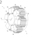
- Fig.1 A perspective view of a temple motor design that is known from the state of the art can be seen.
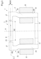
- Fig.2 A more schematic representation of the temple engine is shown in a section in axial direction, where in Fig.2 In addition, the field lines of the magnetic flux are illustrated by the dashed lines.
- the reference numerals are provided with an apostrophe or a dash.
- the temple motor is designated as a whole with the reference numeral 1'.
- the characteristic of a temple motor is that the stator 2' has a plurality of coil cores 25', each of which comprises a longitudinal leg 26' that extends parallel to the axial direction A'.
- the axial direction A' refers to the direction that is defined by the desired axis of rotation of the rotor 3', i.e. the axis of rotation about which the rotor 3' rotates in the operating state when it is in a centered and non-tilted position in the radial plane E', which is perpendicular to the axial direction A', with respect to the stator 2'.
- Each longitudinal leg 26' extends from a first, lower end as shown, in the axial direction A' to a second, upper end as shown.
- Each coil core 25' comprises, in addition to the longitudinal leg 26', a transverse leg 27', which is provided at the second end of the longitudinal leg 26' and which extends radially inwards, i.e. essentially at right angles to the longitudinal leg 26'.
- the coil cores 25' each have the shape of an L, with the transverse legs 27' forming the short legs of the L.
- the rotor 3' is then arranged between the transverse legs 27'.
- Fig.1 and in Fig.2 Only the magnetically active core 31' of the rotor 3' is shown, which is designed here as a disk-shaped permanent magnet. The magnetization of the permanent magnet is shown by the arrow without a reference symbol.
- the coil cores 25' - here, for example, six coil cores 25' - with the longitudinal legs 26' and the transverse legs 27' are arranged in a circle and equidistant around the rotor 3' (inner rotor).
- the first ends of the longitudinal legs 26' are connected in the radial direction by a return 22', which serves to guide the magnetic flux.
- the permanent-magnet, disk-shaped rotor 3' is arranged between the radially inner ends of the transverse legs 27' and rotates in the operating state about the axial direction A', wherein the rotor 3' is magnetically driven without contact and is magnetically mounted without contact with respect to the stator 2', and wherein the radial position of the rotor 3' is regulated so that it is in a centered position between the transverse legs 27'.
- the longitudinal legs 26' carry windings.
- the windings are designed, for example, such that a concentrated winding 61' is wound around each longitudinal leg 26', i.e. the coil axis of each concentrated winding 61' extends in the axial direction A'.
- the coil axes of the concentrated windings 61' run parallel to the desired axis of rotation and that the concentrated windings 61' are not arranged in the radial plane E'.
- the radial plane E' is the plane perpendicular to the axial direction A' in which the rotor 3' or the magnetically active core 31' of the rotor 3' is mounted in the operating state.
- the temple motor design is that there are no windings or winding heads of the stator in the radial plane E'.
- the outlet of the centrifugal pump can be located in the plane in which the impeller of the pump rotor rotates, i.e. the outlet is at the same height in the axial direction A' as the vanes of the pump rotor, without the windings of the stator causing interference.
- This central, i.e. middle, arrangement of the pump outlet is particularly favorable from a hydrodynamic perspective and with regard to the passive support and stabilization of the rotor against tilting.
- the ratio of the diameter and the height of the magnetically active core 31' measured in the axial direction A' is within a certain range. If the diameter of the magnetically active core 31' is increased, its height should also be increased so that the ratio of diameter and height remains at least approximately constant. A greater height of the magnetically active core 31' can, however, lead to the magnetic flux from the magnetically active core 31' of the rotor 3' no longer being completely guided into the transverse legs 27' (as in Fig.2 shown), but as in Fig. 2a shown, is partially guided from the magnetically active core 31' directly - i.e.
- an object of the invention to propose an electromagnetic rotary drive which is designed as a temple motor and which comprises a rotor which can be driven magnetically without contact and which can be mounted magnetically without contact, whereby the electromagnetic rotary drive can be designed to be very compact without having to make concessions to the torque which can be exerted on the rotor or to the quality of the magnetic bearing of the rotor. It is also an object of the invention to propose a centrifugal pump which comprises such a rotary drive. Furthermore, the invention is intended to propose a pump unit for such a centrifugal pump which can also be designed in particular for single use.
- an electromagnetic rotary drive which is designed as a temple motor, with a rotor which comprises a ring-shaped or disk-shaped magnetically active core, and with a stator which is designed as a bearing and drive stator, with which the rotor can be driven in the operating state in a contactless magnetic manner about a desired axis of rotation which defines an axial direction, and with which the rotor can be mounted in a contactless magnetic manner with respect to the stator, wherein the rotor is actively magnetically mounted in a radial plane perpendicular to the axial direction, and is passively magnetically stabilized in the axial direction and against tilting, wherein the stator has a plurality of coil cores, each of which comprises a longitudinal leg which extends in the axial direction, and a transverse leg arranged in the radial plane which extends from the longitudinal leg in a radial direction, and is delimited by an end face which faces the magnetically active core of the rotor, and wherein at least
- Each longitudinal leg comprises a first section and a second section which are arranged adjacent to one another with respect to the axial direction, the transverse leg being arranged on the second section, the end face of the transverse leg being at a first distance in the radial direction from the first section of the associated longitudinal leg and a second distance in the radial direction from the second section, and the second distance being greater than the first distance.
- This design allows the coil cores to be arranged on a circle with a smaller radius at their ends facing away from the transverse legs, which enables a very compact design of the stator.
- the longitudinal legs in their second section have a larger diametrical distance from one another, so that the diameter of the magnetically active core can be increased without the risk of the magnetic flux from the rotor passing directly into the longitudinal legs of the coil cores.
- increasing the diameter of the magnetically active core of the rotor has a beneficial effect on the performance of the electromagnetic rotary drive because this allows the torque acting on the rotor to be increased.
- first section and the second section are arranged parallel to each other for each longitudinal leg and are connected to each other by a transition region in which the radial distance from the associated end face changes from the first distance to the second distance. This can be achieved, for example, by a cranked design of the coil cores.
- the magnetically active core of the rotor has a rotor height which is the maximum extension of the magnetically active core in the axial direction, wherein the rotor height is greater than a stator pole height which is determined by the maximum extension of the end faces of the transverse legs in the axial direction.
- the magnetically active core of the rotor is particularly preferably designed to be permanently magnetic, i.e. it comprises at least one permanent magnet or it consists of a permanent magnetic material. It is also preferred that each end face of the transverse legs has the same extension in the axial direction, so that for each end face its respective extension in the axial direction is equal to the stator pole height.
- the magnetically active core of the rotor has a rotor height that is greater than the stator pole height, this results in a concentration of the magnetic flux in the air gap between the end faces and the magnetically active core of the rotor, i.e. the magnetic flux density increases in the air gap. Since the axial stiffness of the magnetic stabilization of the rotor increases at least approximately quadratically with the magnetic flux density in the air gap, the axial stiffness increases disproportionately with the rotor height. The fact that the rotor height is greater than the stator pole height therefore results in an increase in the axial stiffness of the magnetic bearing or stabilization of the rotor.
- the ratio of the outer diameter of the magnetically active core of the rotor and the rotor height does not fall below the value of 2.8.
- the second distance is greater than half of a stator pole height, which is determined by the maximum extension of the end faces of the transverse legs in the axial direction. This makes it particularly efficient to prevent the magnetic flux from passing from the magnetically active core of the rotor directly into the longitudinal legs of the coil cores and vice versa.
- the magnetically active core comprises a central region which is arranged with respect to the axial direction between a first edge region and a second edge region and which has a rotor diameter, wherein the first edge region forms a first axial boundary surface of the magnetically active core which has a first edge diameter, wherein the second edge region forms a second axial boundary surface of the magnetically active core which has a second edge diameter, and wherein each edge diameter is smaller than the rotor diameter.
- the radially outer region of the magnetic core of the rotor can be designed with a lower height - measured in the axial direction - than the region between the first and second axial boundary surfaces.
- the central region has a central height, which is the extension of the central region in the axial direction, the central height being the same as the stator pole height.
- the radially outer region of the magnetically active core of the rotor i.e. the region which is directly opposite the end faces of the cross legs, has the same extension in the axial direction as the end faces of the cross legs, so that a very high magnetic flux density results in the air gap, which is also advantageous with regard to the torque which drives the rotation of the rotor.
- the magnetically active core has an outer surface that runs parallel to the axial direction neither between the central region and the first axial boundary surface nor between the central region and the second axial boundary surface. This makes it possible to ensure that the field lines of the magnetic flux between the central region and the two axial boundary surfaces do not emerge perpendicular to the axial direction from the magnetically active core of the rotor, but at an angle that is smaller than 90°. This means that the field lines enter the transverse legs of the coil cores further outward with respect to the radial direction, which improves the magnetic bearing or stabilization of the rotor.
- At least one of the first and second edge regions is designed in the form of a truncated cone or in the form of a spherical disk or in the form of a paraboloid disk.
- Such designs make it possible in particular to ensure that the outer surface which delimits the magnetically active core of the rotor does not run parallel to the axial direction, both between the central region and the first axial delimiting surface and between the central region and the second axial delimiting surface, so that the field lines of the magnetic flux exit or enter the magnetically active core of the rotor at an angle other than 90°.
- the first and second edge areas can be designed differently.
- the first edge area can be designed in the shape of a truncated cone and the second edge area in the shape of a spherical disk.
- the first edge area and the second edge area can be designed in the same way.
- two concentrated windings are provided on each longitudinal leg, each of which surrounds the respective longitudinal leg and which are arranged adjacent to one another in the axial direction. This makes it possible to use one of the concentrated windings as a drive coil and the other of the two concentrated windings as a control coil, with the superposition of the electromagnetic fields generated by all drive coils and all control coils then causing the drive and the contactless magnetic bearing of the rotor.
- the two concentrated windings arranged axially adjacent to one another on the same longitudinal leg should not touch one another. This can advantageously be achieved in such a way that a control device or part of a control device for controlling and regulating the electromagnetic rotary drive is arranged between these two concentrated windings with respect to the axial direction.
- This control device can also include power electronics for the concentrated windings, for example.
- the control device arranged between the two concentrated windings is preferably designed as a circuit board or PCB (printed circuit board).
- the invention further proposes a centrifugal pump for conveying a fluid, which is characterized in that the centrifugal pump comprises an electromagnetic rotary drive which is designed according to the invention, wherein the rotor of the electromagnetic rotary drive is designed as the rotor of the centrifugal pump.
- the centrifugal pump comprises a pump unit with a pump housing which comprises an inlet and an outlet for the fluid to be conveyed, wherein the rotor is arranged in the pump housing and comprises a plurality of vanes for conveying the fluid, wherein the pump unit is designed such that the pump unit can be inserted into the stator such that the magnetically active core of the rotor is surrounded by the end faces of the transverse legs.
- the invention proposes a pump unit for a centrifugal pump, which is characterized in that the pump unit is designed for a centrifugal pump which is designed according to the invention.
- the pump housing comprises a base part and a cover, which are sealingly connected to one another, wherein the outlet of the pump housing is arranged completely in the base part.
- the rotor has a central bore which extends completely through the rotor in the axial direction, so that the axial thrust generated by the blades is at least partially compensated.
- the pump unit is designed for detachable connection to the stator of the centrifugal pump according to the invention.
- the pump unit is designed as a disposable device for single use.
- Fig.3 shows a section in the axial direction through a first embodiment of a rotary drive according to the invention, which is designated overall by the reference number 1.
- Fig.4 another view of the first embodiment from the axial direction.
- the electromagnetic rotary drive 1 is designed as a temple motor and comprises a stator 2, which has a plurality of coil cores 25 - here six coil cores 25 - each of which comprises a longitudinal leg 26 which extends in the axial direction A, as well as a transverse leg 27 arranged perpendicular to the longitudinal leg 26, which extends in a radial direction, and is limited by an end face 211.
- the coil cores 25 are arranged equidistantly on a circular line, so that the end faces 211 surround a rotor 3 of the electromagnetic rotary drive 1.
- a concentrated winding 61 is arranged on each longitudinal leg 26, which surrounds the respective longitudinal leg 26.
- the rotor 3 is magnetically mounted in a contactless manner with respect to the stator 2. Furthermore, the rotor 3 can be driven in a contactless manner with respect to the stator 2 to rotate about a target axis of rotation.
- the target axis of rotation refers to the axis about which the rotor 3 rotates in the operating state when the rotor 3 is in a centered and non-tilted position with respect to the stator 2, as shown in Fig.3
- This target axis of rotation defines an axial direction A.
- the target axis of rotation defining the axial direction A coincides with the center axis of the stator 2.
- a radial direction refers to a direction which is perpendicular to the axial direction A.
- the rotor 3 comprises a magnetically active core 31, which is ring-shaped or disk-shaped.
- the magnetically active core 31 is as shown in Fig.3 designed as a disk and defines a magnetic center plane C.
- the magnetic center plane C of the magnetically active core 31 of the rotor 3 refers to the plane perpendicular to the axial direction A in which the magnetically active core 31 of the rotor 3 is mounted in the operating state when the rotor 3 is not tilted and is not deflected in the axial direction A.
- the magnetic center plane C is the geometric center plane of the magnetically active core 31 of the rotor 3, which lies perpendicular to the axial direction A.
- the plane in which the magnetically active core 31 of the rotor 3 is mounted in the operating state between the end faces 211 in the stator 2 is also referred to as the radial plane E.
- the radial plane defines the xy plane of a Cartesian coordinate system whose z axis runs in the axial direction A. If the magnetically active core 31 of the rotor 3 is not tilted and not deflected with respect to the axial direction (A), the radial plane E coincides with the magnetic center plane C.
- the radial position of the magnetically active core 31 or the rotor 3 refers to the position of the rotor 3 in the radial plane E.
- the rotor 3 can of course also comprise further components such as casings or encapsulations, which are preferably made of a plastic, or of a metal or a metal alloy or of a ceramic or a ceramic material. Furthermore, the rotor 3 can also have blades for mixing, stirring or pumping fluids (see e.g. Fig. 16 ) or other components.
- the rotor 3 and in particular the magnetically active core 31 of the rotor 3 is surrounded by the radially outwardly arranged transverse legs 27 of the coil cores 25 of the stator 2.
- the transverse legs 27 thus form a plurality of distinct stator poles, here six stator poles.
- the longitudinal legs 26 of the coil cores 25 each extend from a first end, which is the lower end as shown, in the axial direction A to a second end, which is the upper end as shown.
- the transverse legs 27 are arranged at the upper ends of the longitudinal legs 26. Each transverse leg 27 extends in the radial direction towards the rotor 3.
- the magnetically active core 31 of the rotor 3 is in its desired position during operation, the magnetically active core 31 is centered between the end faces 211 of the transverse legs 27, so that the transverse legs 27 are in the magnetic center plane C or in the radial plane E (these two planes are the same in this case).
- the concentrated windings 61 are arranged below the radial plane E as shown and are aligned so that their coil axes run in the axial direction A.
- All first ends of the longitudinal legs 26 - i.e. the lower ends as shown - are connected to one another by a return 22.
- the return 22 is preferably designed in a ring shape. Such designs are possible (see Fig.3 ), in which the return path 22 extends radially inward along all the first ends of the longitudinal legs 26. However, it is also possible for the return path 22 to have a plurality of recesses along its circumference, each of which accommodates one of the first ends. In other embodiments, the return path can also comprise a plurality of ring segments, each of which is arranged between two coil cores 25 adjacent in the circumferential direction in the region of the first ends.
- the longitudinal legs 26 of the coil cores 25 carry the windings designed as concentrated windings 61, with exactly one concentrated winding 61 being arranged around each longitudinal leg 26 in the first exemplary embodiment.
- these concentrated windings 61 generate those electromagnetic rotating fields with which a torque is caused on the rotor 3 and with which an arbitrarily adjustable transverse force can be exerted on the rotor 3 in the radial direction, so that the radial position of the rotor 3, i.e. its position in the radial plane E perpendicular to the axial direction A, can be actively controlled or regulated.
- the "magnetically active core 31" of the rotor 3 refers to that region of the rotor 3 which magnetically interacts with the stator 2 for the generation of torque and for the generation of the magnetic bearing forces.
- the magnetically active core 31 is designed in the shape of a disk. Furthermore, the magnetically active core 31 is designed to be permanent magnetic.
- the magnetically active core 31 can comprise at least one permanent magnet, but also several permanent magnets or - as in the exemplary embodiment described here - can consist entirely of a permanent magnetic material, so that the magnetically active core 31 is the permanent magnet.
- the magnetization of the magnetically active core of the rotor 3 is in Fig.3 and in Fig.4 each represented by the arrow without reference symbol in the magnetically active core 31.
- the magnetically active core 31 is therefore magnetized in the radial direction.
- Permanent magnets are usually ferromagnetic or ferrimagnetic materials that are hard magnetic, i.e. have a high coercive field strength
- the coercive field strength is the magnetic field strength that is required to demagnetize a material.
- a permanent magnet is understood to be a material that has a coercive field strength, or more precisely a coercive field strength of the magnetic polarization, that is more than 10,000 A/m.
- Both the ring-shaped return path 22 and the coil cores 25 of the stator 2 are each made of a soft magnetic material because they serve as flux guiding elements for guiding the magnetic flux.
- Fig.5 shows for better understanding a view of a single coil core 25 and Fig.6 a perspective view of the coil core 25.
- Suitable soft magnetic materials for the coil cores 25 and the return path 22 are, for example, ferromagnetic or ferrimagnetic materials, i.e. in particular iron, nickel-iron, cobalt-iron, silicon-iron or mu-metal.
- ferromagnetic or ferrimagnetic materials i.e. in particular iron, nickel-iron, cobalt-iron, silicon-iron or mu-metal.
- a design as a stator laminated core is preferred for the stator 2, in which the coil cores 25 and the return path 22 are laminated, i.e. they consist of several thin sheet metal elements that are stacked.
- a coil core 25 shows Fig.7 a perspective view of such a sheet metal element 251.
- a plurality of such sheet metal elements 251 are then stacked to produce a coil core 25.
- a single sheet metal element 251 of a ferromagnetic coil core 25 typically has a sheet thickness d of 0.2 mm to 0.5 mm. The eddy current losses are usually lower the thinner the sheet metal elements 251 are, ie the smaller the sheet thickness d is.
- the coil cores 25 and the return path 22 may consist of pressed and then sintered grains of the materials mentioned.
- the metallic grains are preferably embedded in a plastic matrix so that they are at least partially insulated from one another, which minimizes eddy current losses.
- Soft magnetic composite materials which consist of electrically insulated and pressed metal particles, are therefore also suitable for the stator.
- these soft magnetic composite materials which are also referred to as SMC (Soft Magnetic Composites)
- SMC Soft Magnetic Composites
- the magnetically active core 31 of the rotor 3 interacts with the stator 2 according to the principle of the bearingless motor described above, in which the rotor 3 can be driven magnetically without contact and can be supported magnetically without contact with respect to the stator 2.
- the Stator 2 is designed as a bearing and drive stator, with which the rotor 3 can be driven magnetically around the target axis of rotation in the operating state without contact - in other words can be set in rotation - and can be magnetically supported without contact with respect to the stator 2.
- Three degrees of freedom of the rotor 3 namely its position in the radial plane E and its rotation, can be actively controlled.
- the magnetically active core 31 of the rotor 3 is passively magnetically stabilized, i.e. cannot be controlled, by reluctance forces.
- the magnetically active core 31 of the rotor 3 is also passively magnetically stabilized with regard to the remaining two degrees of freedom, namely tilting with respect to the radial plane E perpendicular to the target axis of rotation.
- the rotor 3 is thus passively magnetically supported or passively magnetically stabilized by the interaction of the magnetically active core 31 with the coil cores 25 in the axial direction A and against tilting (a total of three degrees of freedom) and actively magnetically supported in the radial plane (two degrees of freedom).
- an active magnetic bearing also refers to one that can be actively controlled or regulated, for example via the electromagnetic rotating fields generated with the concentrated windings 61.
- a passive magnetic bearing or a passive magnetic stabilization refers to one that cannot be controlled or regulated.
- the passive magnetic bearing or stabilization is based, for example, on reluctance forces, which bring the rotor 3 back to its target position when it is deflected from its target position, for example when it is shifted or deflected in the axial direction A or when it is tilted.
- a radial bearing or a radial bearing refers to a bearing of the rotor 3 with which the radial position of the rotor 3 can be stabilized, i.e. a bearing which supports the rotor 3 in the radial plane E and thus with respect to its radial position.
- An axial bearing or an axial bearing or an axial stabilization or an axial stabilization refers to a bearing or a stabilization of the rotor 3 with which, on the one hand, the position of the rotor 3 is stabilized with respect to the axial direction A, and with which, on the other hand, the rotor 3 is stabilized against tilting.
- Such tilting represents two degrees of freedom and refers to deflections in which the current axis of rotation of the rotor 3 no longer points exactly in the axial direction A, but rather encloses an angle other than zero with the desired axis of rotation.
- the magnetic center plane C is no longer in or parallel to the radial plane E, but rather the magnetic center plane C encloses an angle other than zero with the radial plane E.
- the magnetic bearing and the drive of the motor are realized via electromagnetic rotating fields.
- the magnetic drive and bearing function is generated by the superposition of two magnetic rotating fields, which are usually referred to as the drive and control fields.
- These two rotating fields generated with the windings of the stator 2 usually have a number of pole pairs that differs by one. For example, if the drive field has the number of pole pairs p, the control field has the number of pole pairs p+1 or p-1.
- the drive field generates tangential forces acting on the magnetically active core 31 in the radial plane, which cause a torque, which causes rotation around the axial direction A.
- an arbitrarily adjustable transverse force can also be generated on the magnetically active core 31 in the radial plane, with which the position of the magnetically active core 31 in the radial plane can be regulated. It is therefore not possible to divide the electromagnetic flux generated by the concentrated windings 61 into an (electro-)magnetic flux that only drives the rotation and an (electro-)magnetic flux that only realizes the magnetic bearing.
- the drive and control fields it is possible to use two different winding systems, namely one for generating the drive field and one for generating the control field.
- the coils for generating the drive field are then usually referred to as drive coils and the coils for generating the control field as control coils (see the Fig. 14 and in Fig. 15
- the current that is impressed into these coils is then referred to as the drive current or as the control current.
- the magnetically active core 31 of the rotor 3 is designed, for example, as is particularly the case in Fig.3 it can be seen that it has a rotor height HR, which is given by the maximum extension of the magnetically active core 31 in the axial direction A.
- the magnetically active core 31 is designed as a whole with a height in the axial direction A, which is equal to the rotor height HR.
- the magnetically active core is designed as a circular disk, or as a disk of a circular cylinder, whereby this disk has a height in the axial direction A, which is the rotor height HR.
- the magnetically active core 31 also has a rotor diameter RZ, which is constant over the entire axial extension of the magnetically active core 31.
- the magnetically active core 31 has a rectangular profile, with the two side lengths of the rectangle being the rotor height HR and the rotor diameter RZ.
- the magnetically active core 31 can of course also be designed as an annular disk.
- the transverse legs 27 of the coil cores 25 have a stator pole height HS, which is defined by the maximum extension of the end faces 211 of the transverse legs 27 in the axial direction A.
- all end faces 211 have the same extension in the axial direction A, so that each end face 211 has the same maximum extension in the axial direction A, namely the stator pole height HS.
- each end face 211 is designed such that its axial height is constant in the circumferential direction. Then the axial height of each end face 211 is equal to the stator pole height HS.
- stator pole height HS is equal to the rotor height HR.
- each longitudinal leg 26 of the coil cores 25 has a first section 261 (see in particular Fig.5 ) and a second section 262, wherein the first section 261 and the second section 262 are arranged adjacent to one another with respect to the axial direction A.
- the transverse leg 27 is arranged on the second section 262.
- the end face 211 of the transverse leg 27 has a first distance A1 in the radial direction from the first section 261 of the associated longitudinal leg 26, and a second distance A2 in the radial direction from the second section 262, wherein the second distance A2 is greater than the first distance A1.
- each longitudinal leg 26 is designed in such a way that the second section 262 is displaced outwards in the radial direction with respect to the first section 261, so that the space available for the rotor 3 between the end faces 211 increases without the risk of a direct transfer of the magnetic flux between the longitudinal leg 26 and the magnetically active core 31 of the rotor 3.
- the second sections 262 are offset radially outward with respect to the radial direction and relative to the first sections 261, the distance, namely the second distance A2, between the longitudinal legs 26 and the end faces 211 increases in the region of the second sections 262.
- the distance between the magnetically active core 31 of the rotor and the longitudinal legs 26 also increases, particularly in the region of the second sections 262.
- first section 261 and the second section 262 are arranged parallel to one another and are connected to one another by a transition region 263 in which the radial distance from the associated end face 211 changes from the first distance A1 to the second distance A2.
- This transition region 263 is preferably designed with a rectangular profile like the first section 261 and the second section 262, wherein its longitudinal axis encloses an angle other than zero with the axial direction A.
- the second distance A2 ( Fig.5 ) is greater than half the stator pole height HS, i.e. A2 > HS. It is particularly preferred if the second distance A2 is greater than 1.1 times the first distance A1, i.e. A2 > 1.1 A2. It is preferred that the second distance A2 is greater than 0.7 times the stator pole height HS, i.e. A2 > 0.7 HS.
- the second distance A2 is greater than 1.2 times the first distance A1, i.e. A2 > 1.2•A2. It is preferred that the second distance A2 is greater than 0.8 times the stator pole height HS, i.e. A2 > 0.8•HS.
- the second distance A2 is greater than 1.25 times the first distance A1, i.e. A2 > 1.25•A2. It is preferred that the second distance A2 is greater than the stator pole height HS, i.e. A2 > HS.
- Fig.8 shows in one of the Fig.3 corresponding representation shows the first embodiment of the rotary drive 1 according to the invention with a first variant for the rotor 3 or the magnetically active core 31 of the rotor 3.
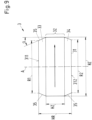
- Fig.9 still this first variant of the magnetically active core 31.
- the magnetically active core 31 of the rotor 3 is designed such that it has a rotor height HR which is greater than the stator pole height HS.
- the magnetically active core 31 is delimited with respect to the axial direction A by a first axial boundary surface 311 and by a second axial boundary surface 312, both of which are perpendicular to the axial direction A and are thus parallel to one another.
- the vertical distance between the first axial boundary surface 311 and the second axial boundary surface 312 is the rotor height HR in this embodiment.
- the magnetically active core 31 of the rotor 3 By designing the magnetically active core 31 of the rotor 3 with a rotor height HR that is greater than the stator pole height HS, the axial rigidity of the magnetic bearing or the magnetic stabilization of the rotor 3 can be significantly improved, because the higher design of the magnetically active core 31 with respect to the axial direction A leads to a concentration of the magnetic flux density in the air gap between the end faces 211 of the transverse legs 27 and the magnetically active core 31 of the rotor 3.
- This concentration of the flux density in the air gap also results in a significantly stronger gradient of the magnetic flux density during the transition from the (at least approximately) homogeneous field between the end faces 211 and the magnetically active core 31 to the area of the stray field that prevails above or below the transverse legs 27 with respect to the axial direction A.
- the field lines of the magnetic flux are each represented by the dashed lines between the transverse legs 27 and the magnetically active core 31, whereby straight, parallel field lines indicate the area of the homogeneous field and curved field lines indicate the area of the stray fields.
- the magnetically active core 31 has a central region 32 which is arranged with respect to the axial direction A between a first edge region 33 and a second edge region 34, wherein both edge regions 33, 34 directly adjoin the central region 32.
- the central region 32 has a diameter which is the rotor diameter RZ.
- the central region 32 has a central height HZ which is smaller than the rotor height HR.
- the first edge region 33 forms the first axial boundary surface 311 of the magnetically active core 31, wherein the first axial boundary surface 311 has a first edge diameter R1, which is its outer diameter.
- the second edge region 34 forms the second axial boundary surface 312 of the magnetically active core 31, wherein the second axial boundary surface 312 has a second edge diameter R2, which is its outer diameter.
- Each of the edge diameters R1 and R2 is smaller than the rotor diameter RZ.
- the first edge diameter R1 and the second edge diameter R2 can be the same size, as shown in Fig.9 In other embodiments, the first edge diameter and the second edge diameter can be of different sizes.
- the central region 32 has a rectangular profile in an axial section, which has the central height HZ as the height and the rotor diameter RZ as the width.
- the central region 32 of the magnetically active core 31 is designed such that the central height HZ is equal to the stator pole height HS.
- the first edge region 33 and the second edge region 34 are each designed in the form of a truncated cone, wherein the truncated cone has a diameter at its base which corresponds to the rotor diameter RZ and a smaller diameter at its axial boundary surface 311, 312 facing away from the base, which corresponds to the first edge diameter R1 or the second edge diameter R2.
- the first edge region 311 and the second edge region 312 are designed similarly.
- first edge region 33 and/or the second edge region 34 are designed in the shape of a circular disk with a diameter which corresponds to the first edge diameter R1 or the second edge diameter R2, so that the first edge region 33 and/or the second edge region 34 then have a rectangular profile in an axial section.
- preferred embodiments of the magnetically active core 31 are those in which the magnetically active core 31 has an outer surface that runs parallel to the axial direction A neither between the central region 32 and the first axial boundary surface 311 nor between the central region 32 and the second axial boundary surface 312.
- preferred embodiments are those in which both the first axial boundary surface 311 and the second axial boundary surface are connected to the central region 32 by transitions 35 that run obliquely to the axial direction A or are curved.
- This measure significantly improves the tilting stiffness of rotor 3, i.e. its resistance to tilting or its ability to return from a tilted position to the desired position.
- the first edge region 33 and the second edge region 34 are each designed in the form of a truncated cone.
- the inclination of the truncated cone is described by a truncated cone angle ⁇ , which is given by the acute angle between the transition 35 and the axial direction A.
- the range from 1.2 to 1.6 is preferred, i.e. 1.2 ⁇ HR/HZ ⁇ 1.6, with the truncated cone angle ⁇ being between 15 degrees and 60 degrees, i.e. 15° ⁇ ⁇ ⁇ 60°. It has proven to be advantageous if the truncated cone angle ⁇ is larger, the larger the height ratio HR/HZ is.
- the ratio of the rotor diameter RZ and the rotor height HR is between two and three, i.e. 2 ⁇ RZ/HR ⁇ 3, whereby this ratio can preferably be chosen to be smaller the larger the truncated cone angle ⁇ is.
- the height ratio of the rotor height HR and the central height HZ is particularly preferred to be in the range from 1.3 to 1.5, i.e. 1.3 ⁇ HR/HZ ⁇ 1.5, with the truncated cone angle ⁇ being between 20 degrees and 30 degrees, i.e. 20° ⁇ ⁇ ⁇ 30°.
- the range from 2.3 to 2.7 is particularly preferred, i.e. 2.3 ⁇ RZ/HR ⁇ 2.7.
- a magnetic field acts, for example, in the area of the magnetically active core 31 which corresponds to the left end face 211 ( Fig.8 ) in the axial direction A, a force component that is opposite to a force component in the axial direction A that acts in the area of the magnetically active core 31 that is opposite the right-hand end face 211 as shown.
- These two force components in the axial direction A thus exert a torque on the magnetically active core 31, which brings it back to its desired position, i.e. into a non-tilted position in which the magnetic center plane C is perpendicular to the axial direction A.
- the magnetically active core 31 of the rotor 3 gets into a position that is shifted or deflected with respect to the axial direction A, the magnetic center plane C is still perpendicular to the axial direction A, but is shifted parallel downwards (as shown) or upwards with respect to the radial plane E.
- a force component acts in the axial direction A that is in the same direction as a force component in the axial direction A that acts in the area of the magnetically active core 31 that is opposite the right end face 211 as shown.
- These two force components thus exert a force on the magnetically active core 31, which brings it back to its desired position, in which the magnetic center plane C lies in the radial plane E.
- Fig.10 illustrates a second variant for the magnetically active core 31 of the rotor 3.
- the magnetically active core 31 is designed as a whole with a height in the axial direction A which is equal to the rotor height HR. Again, the rotor height HR is greater than the stator pole height HS.
- the magnetically active core 31 has no distinct edge regions that can be distinguished from a central region.
- the magnetically active core 31 is designed as a circular disk or as a disk of a circular cylinder, whereby this disk has a diameter that is the rotor diameter RZ and a height in the axial direction that is the rotor height HR.
- the magnetically active core 31 can of course also be designed as an annular disk.
- Fig. 11 shows a third variant for the magnetically active core 31 in a section in the axial direction.
- the third variant largely corresponds to the one in Fig.9 illustrated first variant, but has a central bore 36 which extends in the axial direction A through the entire magnetically active core 31 from the first axial boundary surface 311 to the second axial boundary surface 312.
- Fig. 12 shows a fourth variant for the magnetically active core 31.
- the fourth variant largely corresponds to the one in Fig.9 shown first variant, but differs in the design of the first edge region 33 and the second edge region 34.
- both edge regions 33, 34 are each designed in the form of a spherical disk or in the form of a paraboloid disk, i.e. the transitions 35 are each curved, for example as part of a spherical shell or as part of a paraboloid.
- the inclination of the transitions 35 can be described, for example, by an inclination angle ⁇ , which can be determined in the same way as the truncated cone angle ⁇ .
- the inclination angle ⁇ is the acute angle which a tangent to the transition 35 forms with the axial direction A.
- the same explanations apply to the inclination angle ⁇ as to the truncated cone angle ⁇ .
- Fig. 13 shows a fifth variant for the magnetically active core 31.
- the fifth variant largely corresponds to the one in Fig.9 shown first variant, but differs in the design of the first edge region 33.
- the fourth variant only the second edge region 34 is designed in the form of a truncated cone, while the first edge region is designed in the form of a spherical disk or in the form of a paraboloid disk.
- Fig. 14 shows a perspective view of a second embodiment of an electromagnetic rotary drive 1 according to the invention.
- Fig. 15 the second embodiment in a section in axial direction A.
- the stator 2 of the electromagnetic rotary drive 1 is designed such that two concentrated windings 61a, 61b are provided on each longitudinal leg 26, each of which surrounds the respective longitudinal leg 26 and which are arranged adjacent to one another with respect to the axial direction A.
- This embodiment is particularly suitable for designs based on the principle of the bearingless motor, in which separate winding systems are provided for generating the drive field and the control field.
- one concentrated winding 61a can be used as the drive coil 61a
- the other concentrated Winding 61b can be used as control coil 61b.
- the drive field which is an electromagnetic rotating field
- the control field which is also an electromagnetic rotating field
- the superimposition of the drive field and the control field then allows the tangential forces on the rotor 3 to be generated, which generate the torque to drive the rotation, as well as an arbitrarily adjustable transverse force in the radial plane E, with which the position of the magnetically active core 31 in the radial plane can be actively controlled.
- the design with separate drive coils 61a and separate control coils 61b can simplify the control or regulation of the electromagnetic rotary drive.
- This can be advantageously achieved in such a way that a control device 62 or part of a control device 62 for controlling and regulating the electromagnetic rotary drive 1 is arranged between the drive coil 61a and the control coil 61b with respect to the axial direction A.
- This control device 62 can also comprise power electronics for the concentrated windings 61a, 61b, for example.
- this control device 62 can serve to control and regulate the control coils 61b.
- the control device arranged between the two concentrated windings is preferably designed as a circuit board or PCB (printed circuit board).
- the invention further proposes a centrifugal pump 100 for conveying a fluid, which is characterized in that the centrifugal pump 100 comprises an electromagnetic rotary drive 1 which is designed according to the invention, wherein the rotor 3 of the electromagnetic rotary drive 1 is designed as the rotor 3 of the centrifugal pump 100.
- Fig. 16 shows an embodiment of a centrifugal pump according to the invention, which is designated overall by the reference numeral 100, in a section in the axial direction A.
- the centrifugal pump 100 comprises a pump unit 50 with a pump housing 51, which comprises an inlet 52 and an outlet 53 for the fluid to be conveyed, wherein the rotor 3 is arranged in the pump housing 51, and comprises a plurality of vanes 54 for conveying the fluid.
- the pump unit 50 is designed such that the pump unit 50 can be inserted into the stator 2 such that the magnetically active core of the rotor 31 is surrounded by the end faces 211 of the transverse legs 27.
- the rotor 3 is designed as an integral rotor because it is both the rotor 3 of the electromagnetic rotary drive 1 and the rotor 3 of the centrifugal pump 100, with which the fluid is conveyed.
- the rotor 3 thus fulfills three functions in one: It is the rotor 3 of the electromagnetic drive 1, it is the rotor 3 of the magnetic bearing, and it is the impeller with which the fluid or fluids are acted upon.
- This design as an integral rotor offers the advantage of a very compact and space-saving design.
- FIG. 17 a somewhat more detailed representation of the pump unit 50 of the centrifugal pump 100 in a section along the section line XVII-XVII in Fig. 18.
- Fig. 18 shows a plan view of the pump unit 50 from the axial direction A.
- the pump housing 51 of the pump unit comprises a base part 512 and a cover 511, which are sealingly connected to one another, wherein the outlet 53 of the pump housing 51 is arranged completely in the base part 512.
- the cover 511 comprises the inlet 52, which extends in the axial direction A, so that the fluid flows onto the rotor 3 from the axial direction A.
- outlet 53 is arranged completely in the base part 512, so that the outlet 53 has no joints, weld seams or similar connection points.
- the base part 512 and the cover 511 can be connected to one another by a screw connection or by a click connection or by a snap-in connection, by gluing or by various types of welding, for example by infrared welding.
- a sealing element 513 for example an O-ring, between the base part 512 and the cover 511.
- the rotor 3 comprises the plurality of vanes 54 for conveying the fluid. In the embodiment described here, a total of four vanes 54 are provided, this number being exemplary.
- the rotor 3 further comprises a casing 38 with which the magnetically active core 31 of the rotor 3 is enclosed and preferably hermetically encapsulated, so that the magnetically active core 31 of the rotor 3 does not come into contact with the fluid to be conveyed. All vanes 54 are arranged on the casing 38 and are arranged equidistantly with respect to the circumferential direction of the rotor 3. Each vane 54 extends radially outwards and is connected to the casing 38 in a rotationally fixed manner. The vanes 54 can be separate components which are then fixed to the casing 38.
- all vanes 54 may be an integral part of the casing 38, i.e. for the casing 38 to be provided with all blades 54.
- the rotor 3 with the blades 54 forms the impeller or the rotor of the centrifugal pump 100, with which the fluid or fluids are acted upon.
- the rotor 3 comprises the central bore 36, which extends completely through the rotor 3 in the axial direction A.
- This central bore 36 can ensure at least partial axial thrust compensation, so that the passive magnetic axial bearing of the rotor 3 is relieved.
- the pump housing 51 of the pump unit 50 as well as the casing 38 and the vanes 54 are made of one or more plastics.
- Suitable plastics are: polyethylene (PE), low density polyethylene (LDPE), ultra low density polyethylene (ULDPE), ethylene vinyl acetate (EVA), polyethylene terephthalate (PET), polyvinyl chloride (PVC), polypropylene (PP), polyurethane (PU), polyvinylidene fluoride (PVDF), acrylonitrile butadiene styrene (ABS), polyacrylic, polycarbonate (PC), polyetheretherketone (PEEK) or silicone.
- the materials polytetrafluoroethylene (PTFE) and perfluoroalkoxy polymers (PFA), known under the brand name Teflon are also suitable as plastics.
- the pump unit 50 is preferably designed for detachable connection to the stator 2 of the centrifugal pump 100.
- several tabs 57 can be provided on the pump housing 51, for example, which can interact with the stator 2 in the form of a bayonet connection.
- the pump unit 50 is designed as a disposable device for single use, which can be inserted into the stator 2 designed as a reusable device.
- the centrifugal pump 100 is then composed of the pump unit 50, which is designed as a disposable device for single use, and the stator 2, which is designed as a reusable device that is designed for multiple use.
- the stator 2 typically also includes the control, regulation and supply units of the electromagnetic rotary drive 1.
- single-use device and other compositions with the component “single” refer to components or parts that are designed for single use, i.e. that can only be used once as intended and then disposed of. For a new application, a new, previously unused single-use part must then be used.
- the single-use device should therefore be very easy to replace. without requiring a high level of assembly effort.
- the disposable device should be able to be joined to and separated from the reusable device without the use of tools.
- the pump unit 50 can be designed as such a disposable device.
- the centrifugal pump 100 can be used, for example, in medical technology as a blood pump or in the pharmaceutical or biotechnology industry.
- the centrifugal pump 100 is particularly suitable for applications in which a very high degree of purity or sterility of the components that come into contact with the substances to be mixed is essential.
Landscapes
- Engineering & Computer Science (AREA)
- Health & Medical Sciences (AREA)
- Mechanical Engineering (AREA)
- Heart & Thoracic Surgery (AREA)
- Power Engineering (AREA)
- General Engineering & Computer Science (AREA)
- Life Sciences & Earth Sciences (AREA)
- Public Health (AREA)
- Biomedical Technology (AREA)
- Hematology (AREA)
- Cardiology (AREA)
- Animal Behavior & Ethology (AREA)
- General Health & Medical Sciences (AREA)
- Anesthesiology (AREA)
- Veterinary Medicine (AREA)
- Physics & Mathematics (AREA)
- Electromagnetism (AREA)
- Connection Of Motors, Electrical Generators, Mechanical Devices, And The Like (AREA)
- Structures Of Non-Positive Displacement Pumps (AREA)
- Permanent Magnet Type Synchronous Machine (AREA)
Description
- Die Erfindung betrifft einen elektromagnetischen Drehantrieb, eine Zentrifugalpumpe mit einem solchen elektromagnetischen Drehantrieb, sowie eine Pumpeneinheit für eine solche Zentrifugalpumpe gemäss dem Oberbegriff des unabhängigen Patentanspruchs der jeweiligen Kategorie.
- Es sind elektromagnetische Drehantriebe bekannt, die nach dem Prinzip des lagerlosen Motors ausgestaltet sind und betrieben werden. Mit dem Begriff lagerloser Motor ist dabei ein elektromagnetischer Drehantrieb gemeint, bei welchem der Rotor vollkommen magnetisch bezüglich des Stators gelagert ist, wobei keine separaten magnetischen Lager vorgesehen sind. Der Stator ist dazu als Lager- und Antriebsstator ausgestaltet, der sowohl Stator des elektrischen Antriebs als auch Stator der magnetischen Lagerung ist. Mit den elektrischen Wicklungen des Stators lässt sich ein magnetisches Drehfeld erzeugen, welches zum einen ein Drehmoment auf den Rotor ausübt, das dessen Rotation um eine Solldrehachse bewirkt, und welches zum anderen eine beliebig einstellbare Querkraft auf den Rotor ausübt, sodass dessen radiale Position aktiv steuerbar bzw. regelbar ist. Somit sind drei Freiheitsgrade des Rotors aktiv regelbar, nämlich seine Rotation sowie seine radiale Position (zwei Freiheitsgrade). Bezüglich dreier weiterer Freiheitsgrade, nämlich seiner Position in axialer Richtung und Verkippungen bezüglich der zur Solldrehachse senkrechten radialen Ebene (zwei Freiheitsgrade), ist der Rotor passiv magnetisch, das heisst nicht ansteuerbar, durch Reluktanzkräfte gelagert bzw. stabilisiert. Das Nichtvorhandensein eines separaten magnetischen Lagers bei vollständiger magnetischer Lagerung des Rotors ist die Eigenschaft, welcher der lagerlose Motor seinen Namen verdankt. In dem Lager- und Antriebsstator lässt sich die Lagerfunktion nicht von der Antriebsfunktion separieren.
- Ein solcher lagerloser Motor hat sich in einer Vielzahl von Anwendungen bewährt. Aufgrund der Abwesenheit von mechanischen Lagern eignet sich der lagerlose Motor insbesondere für Pump-, Misch- oder Rührvorrichtungen, mit denen sehr empfindliche Substanzen gefördert werden, beispielsweise Blutpumpen, oder bei denen sehr hohe Anforderungen an die Reinheit gestellt werden, beispielsweise in der pharmazeutischen Industrie oder in der biotechnologischen Industrie, oder mit denen abrasive oder aggressive Substanzen gefördert werden, welche mechanische Lager sehr schnell zerstören würden, beispielsweise Pumpen oder Mischer für Slurry in der Halbleiterindustrie.
- Ein weiterer Vorteil des Prinzips des lagerlosen Motors ergibt sich bei der Ausgestaltung des Rotors als Integralrotor, der sowohl der Rotor des elektromagnetischen Drehantriebs ist, als auch der Rotor der Pumpe. Neben der berührungslosen magnetischen Lagerung resultiert hier der Vorteil einer sehr kompakten und platzsparenden Ausgestaltung.
- Zudem erlaubt das Prinzip des lagerlosen Motors auch Ausgestaltungen, beispielsweise von Zentrifugalpumpen, bei denen der Rotor sehr leicht vom Stator trennbar ist. Dies ist ein sehr grosser Vorteil, weil damit beispielsweise der Rotor bzw. die Pumpeneinheit, welche den Rotor umfasst, als Einmalteil für den Einmalgebrauch ausgestaltet werden kann. Solche Einmalanwendungen ersetzen heute häufig Prozesse, bei denen früher aufgrund der sehr hohen Reinheitsanforderungen alle diejenigen Komponenten, welche im Prozess mit den zu behandelnden Substanzen in Kontakt kommen, aufwändig gereinigt und sterilisiert werden müssen, beispielsweise mittels Dampfsterilisierung. Bei der Ausgestaltung für den Einmalgebrauch werden diejenigen Komponenten, welche mit den zu behandelnden Substanzen in Kontakt kommen, nur genau einmal verwendet und dann bei der nächsten Anwendung durch neue, das heisst ungebrauchte, Einmalteile ersetzt.
- Als Beispiele seien hier die Pharmaindustrie und die biotechnologische Industrie genannt. Hier werden häufig Lösungen und Suspensionen hergestellt, die eine sorgfältige und schonende Förderung von Substanzen verlangen.
- In der Pharmaindustrie müssen beispielsweise bei der Herstellung von pharmazeutisch wirksamen Substanzen höchste Ansprüche an die Reinheit gestellt werden, oft müssen die mit den Substanzen in Kontakt kommenden Komponenten sogar steril sein. Ähnliche Anforderungen ergeben sich auch in der Biotechnologie, beispielsweise bei der Herstellung, Behandlung oder Züchtung von biologischen Substanzen, Zellen oder Mikroorganismen, wo ein extrem hohes Mass an Reinheit gewährleistet sein muss, um die Brauchbarkeit des hergestellten Produkts nicht zu gefährden. Als ein weiteres Beispiel seien hier Bioreaktoren genannt, in denen beispielsweise biologische Substitute für Gewebe oder spezielle Zellen oder andere sehr empfindliche Substanzen gezüchtet werden. Auch hier benötigt man Zentrifugalpumpen, um beispielsweise eine kontinuierliche Durchmischung der Nährflüssigkeit beziehungsweise deren kontinuierliche Zirkulation im Mischbehälter zu gewährleisten. Dabei muss eine sehr hohe Reinheit gewährleistet sein, um die Substanzen oder die erzeugten Produkte vor Kontaminationen zu schützen. Ein weiteres Anwendungsbeispiel sind Blutpumpen, bei denen natürlich höchste Anforderungen an die Reinheit und zudem an die schonende Behandlung insbesondere der roten Blutkörperchen gestellt werden.
- Bei solchen Anwendungen, bei denen eine Zentrifugalpumpe für den Einmalgebrauch ausgelegt ist, setzt sich die Zentrifugalpumpe typischerweise aus einer Einmalvorrichtung und einer wiederverwendbaren Vorrichtung zusammen. Dabei umfasst die Einmalvorrichtung diejenigen Komponenten, die mit den Substanzen in Kontakt kommen, und die als Einmal (single-use) -Teile für den Einmalgebrauch ausgestaltet sind. Dies ist beispielsweise die Pumpeneinheit mit dem Pumpengehäuse und dem darin angeordneten Rotor, welcher das Flügelrad der Zentrifugalpumpe bildet. Die wiederverwendbare Vorrichtung umfasst diejenigen Komponenten, die dauerhaft also mehrfach verwendet werden, beispielsweise den Stator des elektromagnetischen Drehantriebs.
- Eine vorteilhafte und an sich bekannte Ausführungsform eines elektromagnetischen Drehantriebs, der nach dem Prinzip des lagerlosen Motors ausgestaltet werden kann, ist die Ausführung als Tempelmotor, die beispielsweise in der
EP-A-3 232 549 offenbart wird. Auf die Ausgestaltung als Tempelmotor bezieht sich auch die vorliegende Erfindung. InFig. 1 ist in einer perspektivischen Darstellung eine Ausgestaltung eines Tempelmotors zu sehen, die vom Stand der Technik bekannt ist. Zum besseren Verständnis ist inFig. 2 noch eine schematischere Darstellung des Tempelmotors in einem Schnitt in axialer Richtung gezeigt, wobei inFig. 2 zusätzlich die Feldlinien des magnetischen Flusses durch die strichlierten Linien veranschaulicht sind. Ferner zeigtFig. 2a in einer zuFig. 2 analogen Darstellung den Tempelmotor für den Fall, dass der Rotor bezüglich der axialen Richtung ausgelenkt ist. - Um anzuzeigen, dass es sich bei der Darstellung in
Fig. 1 , inFig. 2 und inFig. 2a um eine Vorrichtung aus dem Stand der Technik handelt, sind hier die Bezugszeichen jeweils mit einem Hochkomma bzw. mit einem Strich versehen. Der Tempelmotor ist gesamthaft mit dem Bezugszeichen 1' bezeichnet. - Das Charakteristische eines Tempelmotors ist es, dass der Stator 2' eine Mehrzahl von Spulenkernen 25' aufweist, von denen jeder einen Längsschenkel 26` umfasst, der sich parallel zur axialen Richtung A' erstreckt. Mit der axialen Richtung A' ist dabei diejenige Richtung gemeint, welche durch die Solldrehachse des Rotors 3' definiert ist, also die Drehachse, um welche der Rotor 3' im Betriebszustand rotiert, wenn er in der radialen Ebene E', die senkrecht zur axialen Richtung A' liegt, bezüglich des Stators 2' in einer zentrierten und unverkippten Position ist. Jeder Längsschenkel 26' erstreckt sich von einem ersten, darstellungsgemäss unteren, Ende in axialer Richtung A' bis zu einem zweiten, darstellungsgemäss oberen Ende. Jeder Spulenkern 25' umfasst zusätzlich zu dem Längsschenkel 26' einen Querschenkel 27', welcher jeweils an dem zweiten Ende des Längsschenkels 26' vorgesehen ist, und welcher sich in radialer Richtung nach innen erstreckt, also im Wesentlichen rechtwinklig zum Längsschenkel 26`. Die Spulenkerne 25' haben jeweils die Form eines L, wobei die Querschenkel 27' die kurzen Schenkel des L bilden. Der Rotor 3' ist dann zwischen den Querschenkeln 27` angeordnet. In
Fig. 1 und inFig. 2 ist von dem Rotor 3' nur der magnetisch wirksame Kern 31' des Rotors 3' dargestellt, welcher hier als scheibenförmiger Permanentmagnet ausgestaltet ist. Die Magnetisierung des Permanentmagneten ist durch den Pfeil ohne Bezugszeichen dargestellt. - Die Mehrzahl der Längsschenkel 26`, die sich in axialer Richtung A' erstrecken und an die Säulen eines Tempels erinnern, hat dem Tempelmotor seinen Namen gegeben.
- Bei der in
Fig. 1 undFig. 2 dargestellten Ausgestaltung des Tempelmotors 1' als lagerloser Motor sind die Spulenkerne 25' - hier beispielsweise sechs Spulenkerne 25' - mit den Längsschenkeln 26' und den Querschenkeln 27` kreisförmig und äquidistant um den Rotor 3' herum angeordnet (Innenläufer). Die ersten Enden der Längsschenkel 26` sind in radialer Richtung durch einen Rückschluss 22' verbunden, welcher der magnetischen Flussführung dient. Der permanentmagnetische, scheibenförmige Rotor 3' ist zwischen den radial innenliegenden Enden der Querschenkel 27' angeordnet und rotiert im Betriebszustand um die axiale Richtung A', wobei der Rotor 3' berührungslos magnetisch angetrieben und berührungslos magnetisch bezüglich des Stators 2' gelagert ist, und wobei die radiale Position des Rotors 3' so geregelt wird, dass er sich in einer zentrierten Position zwischen den Querschenkeln 27` befindet. - Um die für den magnetischen Antrieb und die magnetische Lagerung des Rotors 3' notwendigen elektromagnetischen Drehfelder zu erzeugen, tragen die Längsschenkel 26` Wicklungen. Die Wicklungen sind beispielsweise so ausgestaltet, dass um jeden Längsschenkel 26' herum eine konzentrierte Wicklung 61' gewickelt ist, das heisst, die Spulenachse jeder konzentrierten Wicklung 61' erstreckt sich jeweils in axialer Richtung A'. Dabei ist es typisch für den Tempelmotor, dass die Spulenachsen der konzentrierten Wicklungen 61' parallel zur Solldrehachse verlaufen und, dass die konzentrierten Wicklungen 61'nicht in der radialen Ebene E' angeordnet sind. Die radiale Ebene E' ist diejenige Ebene senkrecht zur axialen Richtung A', in welcher der Rotor 3' bzw. der magnetisch wirksame Kern 31' des Rotors 3' im Betriebszustand gelagert wird.
- Einer der Vorteile der Ausgestaltung als Tempelmotor ist es, dass in der radialen Ebene E' keine Wicklungen oder Wickelköpfe des Stators vorhanden sind. Dies ermöglicht es beispielsweise bei einer Anwendung des Tempelmotors in einer Zentrifugalpumpe, dass der Auslass der Zentrifugalpumpe in der Ebene vorgesehen werden kann, in welcher das Flügelrad des Pumpenrotors rotiert, der Auslass also auf gleicher Höhe bezüglich der axialen Richtung A' liegt wie die Flügel des Pumpenrotors, ohne dass dabei die Wicklungen des Stators stören. Diese zentrale, d.h. mittige Anordnung des Pumpenauslasses ist unter hydrodynamischen Aspekten und im Hinblick speziell auf die passive Lagerung und Stabilisierung des Rotors gegen Verkippungen besonders günstig.
- Im Hinblick auf eine möglichst kompakte und leistungsstarke Ausgestaltung des Tempelmotors 1', wie sie beispielsweise auch in Blutpumpen benötigt wird, können verschiedene Massnahmen in Erwägung gezogen werden, deren gleichzeitige Realisierung jedoch nur durch Kompromisse oder Optimierungen möglich ist, weil diese Massnahmen teilweise gegenläufig sind. Im Hinblick auf eine möglichst kompakte Ausgestaltung ist man beispielsweise bemüht, die Längsschenkel 26' auf einem möglichst kleinen Radius anzuordnen. Andererseits ist man bemüht, den magnetisch wirksamen Kern 31' des Rotors 3' mit einem möglichst grossen Durchmesser auszugestalten, weil das auf den Rotor 3' ausübbare Drehmoment - und damit beispielsweise die Leistungsfähigkeit einer Zentrifugalpumpe - im Wesentlichen proportional zum Quadrat des Durchmessers des magnetisch wirksamen Kerns 31' ist. Ein grösserer Durchmesser des magnetisch wirksamen Kerns 31' verlangt dann aber danach, die Längsschenkel 26' auf einem grösseren Radius anzuordnen, damit der Rotor 3' noch zwischen den Querschenkeln 27' der Spulenkerne 25' angeordnet werden kann.
- Zudem ist es insbesondere im Hinblick auf die passive magnetische Stabilisierung des Rotors 3' vorteilhaft, wenn das Verhältnis aus dem Durchmesser und der in axialer Richtung A' gemessenen Höhe des magnetisch wirksamen Kerns 31' in einem bestimmten Bereich liegt. Vergrössert man nun den Durchmesser des magnetisch wirksamen Kerns 31', so sollte auch seine Höhe vergrössert werden, damit das Verhältnis aus Durchmesser und Höhe zumindest ungefähr konstant bleibt. Eine grössere Höhe des magnetisch wirksamen Kerns 31' kann aber dazu führen, dass der magnetische Fluss aus dem magnetisch wirksamen Kern 31' des Rotors 3' nicht mehr vollständig in die Querschenkel 27' geführt wird (so wie in
Fig. 2 gezeigt), sondern wie inFig. 2a dargestellt, teilweise aus dem magnetisch wirksamen Kern 31' direkt - also nicht über die Querschenkel 27' - in die Längsschenkel 26' der Spulenkerne 25' geführt wird. Dies führt in der Summe dazu, dass der magnetisch wirksame Kern 31' nicht mehr korrekt in der radialen Ebene E' gelagert ist, sondern darstellungsgemäss nach unten ausgelenkt wird (Fig. 2a ). Das hat dann wiederum zur Folge, dass, beispielsweise bei Anwendung des lagerlosen Motors in einer Pumpe, das Flügelrad, welches den Rotor 3' mit dem magnetisch wirksamen Kern 31' umfasst, teilweise in den Stator 2' hineingezogen wird und somit teilweise im Stator 2' des Motors 1' verschwindet, und nicht mehr mit dem Auslass bzw. dem Auslasskanal ausgerichtet ist, sondern relativ zu diesem in axialer Richtung verschoben ist. Zusätzlich wird durch die Auslenkung des Rotors 3' nach unten die maximale Axialkraft der passiven magnetischen Lagerung verringert. - Ausgehend von diesem Stand der Technik ist es daher eine Aufgabe der Erfindung, einen elektromagnetischen Drehantrieb vorzuschlagen, der als Tempelmotor ausgestaltet ist, und der einen magnetisch berührungslos antreibbaren sowie magnetisch berührungslos lagerbaren Rotor umfasst, wobei der elektromagnetische Drehantrieb sehr kompakt ausgestaltet werden kann, ohne dass dafür Zugeständnisse an das auf den Rotor ausübbare Drehmoment oder an die Qualität der magnetischen Lagerung des Rotors vonnöten sind. Zudem ist es eine Aufgabe der Erfindung, eine Zentrifugalpumpe vorzuschlagen, die einen solchen Drehantrieb umfasst. Ferner soll durch die Erfindung eine Pumpeneinheit für eine solche Zentrifugalpumpe vorgeschlagen werden, die insbesondere auch für den Einmalgebrauch ausgestaltet werden kann.
- Die diese Aufgabe lösenden Gegenstände der Erfindung sind durch die Merkmale des unabhängigen Patentanspruchs der jeweiligen Kategorie gekennzeichnet.
- Erfindungsgemäss wird also ein elektromagnetischer Drehantrieb vorgeschlagen, der als Tempelmotor ausgestaltet ist, mit einem Rotor, der einen ring- oder scheibenförmigen magnetisch wirksamen Kern umfasst, sowie mit einem Stator, welcher als Lager- und Antriebsstator ausgestaltet ist, mit welchem der Rotor im Betriebszustand berührungslos magnetisch um eine Solldrehachse antreibbar ist, die eine axiale Richtung definiert, und mit welchem der Rotor berührungslos magnetisch bezüglich des Stators lagerbar ist, wobei der Rotor in einer zur axialen Richtung senkrechten radialen Ebene aktiv magnetisch gelagert ist, und in axialer Richtung sowie gegen Verkippungen passiv magnetisch stabilisiert ist, wobei der Stator eine Mehrzahl von Spulenkernen aufweist, von denen jeder einen Längsschenkel umfasst, welcher sich in axialer Richtung erstreckt, sowie einen in der radialen Ebene angeordneten Querschenkel, welcher sich von dem Längsschenkel in einer radialen Richtung erstreckt, und durch eine Stirnfläche begrenzt wird, welche dem magnetisch wirksamen Kern des Rotors zugewandt ist, und wobei an jedem Längsschenkel mindestens eine konzentrierte Wicklung angeordnet ist, welche den jeweiligen Längsschenkel umgibt. Jeder Längsschenkel umfasst einen ersten Abschnitt und einen zweiten Abschnitt, welche bezüglich der axialen Richtung benachbart zueinander angeordnet sind, wobei der Querschenkel an dem zweiten Abschnitt angeordnet ist, wobei die Stirnfläche des Querschenkels von dem ersten Abschnitt des zugehörigen Längsschenkels einen ersten Abstand in radialer Richtung aufweist, und von dem zweiten Abschnitt einen zweiten Abstand in radialer Richtung, und wobei der zweite Abstand grösser ist als der erste Abstand.
- Durch diese Ausgestaltung können die Spulenkerne an ihren den Querschenkeln abgewandten Enden auf einem Kreis mit kleinerem Radius angeordnet werden, was eine sehr kompakte Ausgestaltung des Stators ermöglicht. Gleichzeitig weisen die Längsschenkel in ihrem zweiten Abschnitt einen grösseren diametralen Abstand voneinander auf, sodass der Durchmesser des magnetisch wirksamen Kerns vergrössert werden kann, ohne dass die Gefahr besteht, dass der magnetische Fluss aus dem Rotor direkt in die Längsschenkel der Spulenkerne übertritt. Insbesondere die Vergrösserung des Durchmessers des magnetisch wirksamen Kerns des Rotors wirkt sich vorteilhaft auf die Leistungsfähigkeit des elektromagnetischen Drehantriebs aus, weil hierdurch das auf den Rotor einwirkende Drehmoment vergrössert werden kann.
- In einer bevorzugten Ausgestaltung sind für jeden Längsschenkel der erste Abschnitt und der zweite Abschnitt parallel zueinander angeordnet, und durch einen Übergangsbereich miteinander verbunden, in welchem sich der radiale Abstand von der zugehörigen Stirnfläche von dem ersten Abstand zu dem zweiten Abstand ändert. Dies kann beispielsweise durch eine gekröpfte Ausgestaltung der Spulenkerne realisiert werden.
- Ferner ist es vorteilhaft, wenn der magnetisch wirksame Kern des Rotors eine Rotorhöhe aufweist, welche die maximale Erstreckung des magnetisch wirksamen Kerns in axialer Richtung ist, wobei die Rotorhöhe grösser ist als eine Statorpolhöhe, welche durch die maximale Erstreckung der Stirnflächen der Querschenkel in axialer Richtung festgelegt ist.
- Besonders bevorzugt ist der magnetisch wirksame Kern des Rotors permanentmagnetisch ausgestaltet, das heisst er umfasst mindestens einen Permanentmagneten oder er besteht aus einem permanentmagnetischen Material. Ferner ist es bevorzugt, dass jede Stirnfläche der Querschenkel in der axialen Richtung die gleiche Erstreckung hat, sodass für jede Stirnfläche ihre jeweilige Erstreckung in axialer Richtung gleich der Statorpolhöhe ist.
- Dadurch, dass der magnetisch wirksame Kern des Rotor die Rotorhöhe aufweist, die grösser ist als die Statorpolhöhe, resultiert eine Konzentration des magnetischen Flusses im Luftspalt zwischen den Stirnflächen und dem magnetisch wirksamen Kern des Rotors, das heisst die magnetische Flussdichte nimmt im Luftspalt zu. Da die axiale Steifigkeit der magnetischen Stabilisierung des Rotors zumindest näherungsweise quadratisch mit der magnetischen Flussdichte im Luftspalt zunimmt, nimmt die axiale Steifigkeit überproportional mit der Rotorhöhe zu. Somit resultiert daraus, dass die Rotorhöhe grösser ist als die Statorpolhöhe eine Vergrösserung der axialen Steifigkeit der magnetischen Lagerung bzw. Stabilisierung des Rotors.
- Um die Kippsteifigkeit des Rotors, also seinen Widerstand gegen Verkippungen relativ zu der radialen Ebene, die senkrecht zur axialen Richtung liegt, nicht zu stark zu reduzieren, ist es bevorzugt, dass das Verhältnis aus dem Aussendurchmesser des magnetisch wirksamen Kerns des Rotors und der Rotorhöhe den Wert von 2.8 nicht unterschreitet.
- Ferner ist es eine bevorzugte Massnahme, dass der zweite Abstand grösser ist als die Hälfte einer Statorpolhöhe, welche durch die maximale Erstreckung der Stirnflächen der Querschenkel in axialer Richtung festgelegt ist. Hierdurch lässt es sich besonders effizient vermeiden, dass der magnetische Fluss aus dem magnetisch wirksamen Kern des Rotors direkt in die Längsschenkel der Spulenkerne übertritt und umgekehrt.
- Bei einer bevorzugten Ausführungsform umfasst der magnetisch wirksame Kern einen zentralen Bereich, welcher bezüglich der axialen Richtung zwischen einem ersten Randbereich und einem zweiten Randbereich angeordnet ist, und welcher einen Rotordurchmesser aufweist, wobei der erste Randbereich eine erste axiale Begrenzungsfläche des magnetisch wirksamen Kerns bildet, die einen ersten Randdurchmesser aufweist, wobei der zweite Randbereich eine zweite axiale Begrenzungsfläche des magnetisch wirksamen Kerns bildet, die einen zweiten Randdurchmesser aufweist, und wobei jeder Randdurchmesser kleiner ist als der Rotordurchmesser.
- Bei dieser Ausführungsform kann somit der radial aussenliegende Bereich des magnetischen Kerns des Rotors mit einer geringeren Höhe - gemessen in der axialen Richtung - ausgestaltet werden, als der Bereich zwischen der ersten und der zweiten axialen Begrenzungsfläche. Dies hat den Vorteil, dass ebenfalls eine Vergrösserung der axialen Steifigkeit der magnetischen Stabilisierung resultiert, aber eine deutlich geringere Abnahme der Kippsteifigkeit.
- Vorzugsweise weist der zentrale Bereich eine zentrale Höhe auf, welches die Erstreckung des zentralen Bereichs in axialer Richtung ist, wobei die zentrale Höhe gleich gross ist wie die Statorpolhöhe. Dies hat den Vorteil, dass der radial aussenliegende Bereich des magnetisch wirksamen Kerns des Rotors, also derjenige Bereich, welcher den Stirnflächen der Querschenkel direkt gegenüber liegt, in der axialen Richtung die gleiche Erstreckung hat wie die Stirnflächen der Querschenkel, sodass im Luftspalt eine sehr hohe magnetische Flussdichte resultiert, was auch im Hinblick auf das Drehmoment vorteilhaft ist, welches die Rotation des Rotors antreibt.
- Eine weitere bevorzugte Massnahme ist es, dass der magnetisch wirksame Kern eine Aussenfläche aufweist, die weder zwischen dem zentralen Bereich und der ersten axialen Begrenzungsfläche noch zwischen dem zentralen Bereich und der zweiten axialen Begrenzungsfläche parallel zur axialen Richtung verläuft. Hierdurch lässt es sich realisieren, dass die Feldlinien des magnetischen Flusses zwischen dem zentralen Bereich und den beiden axialen Begrenzungsflächen nicht senkrecht zur axialen Richtung aus dem magnetisch wirksamen Kern des Rotors austreten, sondern unter einem Winkel der kleiner ist als 90°. Hierdurch treten die Feldlinien bezüglich der radialen Richtung weiter aussen in die Querschenkel der Spulenkerne ein, wodurch sich die magnetische Lagerung bzw. Stabilisierung des Rotors verbessert.
- Besonders bevorzugt ist es, dass mindestens einer des ersten und des zweiten Randbereichs in Form eines Kegelstumpfs oder in Form einer Kugelscheibe oder in Form einer Paraboloidscheibe ausgestaltet ist. Durch solche Ausgestaltungen lässt es sich insbesondere realisieren, dass die Aussenfläche, welche den magnetisch wirksamen Kern des Rotors begrenzt, sowohl zwischen dem zentralen Bereich und der ersten axialen Begrenzungsfläche als auch zwischen dem zentralen Bereich und der zweiten axialen Begrenzungsfläche nicht parallel zur axialen Richtung verläuft, sodass hier die Feldlinien des magnetischen Flusses unter einem von 90° verschiedenen Winkel aus dem magnetisch wirksamen Kern des Rotors austreten bzw. in diesen eintreten.
- Der erste und der zweite Randbereich können unterschiedlich ausgestaltet sein. So kann beispielsweise der erste Randbereich kegelstumpfförmig ausgestaltet sein und der zweite Randbereich in Form einer Kugelscheibe. Natürlich ist es auch möglich, dass der erste Randbereich und der zweite Randbereich gleichartig ausgestaltet sind.
- Gemäss einem zweiten bevorzugten Ausführungsbeispiel sind an jedem Längsschenkel zwei konzentrierte Wicklungen vorgesehen, von denen jede den jeweiligen Längsschenkel umgibt, und die bezüglich der axialen Richtung benachbart zueinander angeordnet sind. Hierdurch ist es möglich, eine der konzentrierten Wicklungen als Antriebsspule zu verwenden und die andere der beiden konzentrierten Wicklungen als Steuerspule, wobei dann die Überlagerung der von allen Antriebsspulen und von allen Steuerspulen generierten elektromagnetischen Felder den Antrieb und die berührungslose magnetische Lagerung des Rotors bewirken.
- Die auf dem gleichen Längsschenkel axial zueinander benachbart angeordneten beiden konzentrierten Wicklungen sollen sich nicht berühren. Dies kann vorteilhafter Weise so realisiert werden, dass bezüglich der axialen Richtung zwischen diesen beiden konzentrierten Wicklungen eine Kontrolleinrichtung oder ein Teil einer Kontrolleinrichtung zur Ansteuerung und zur Regelung des elektromagnetischen Drehantriebs angeordnet ist. Diese Kontrolleinrichtung kann beispielsweise auch Leistungselektronik für die konzentrierten Wicklungen umfassen. Vorzugsweise ist die zwischen den beiden konzentrierten Wicklungen angeordnete Kontrolleinrichtung als Platine bzw. PCB (printed circuit board) ausgestaltet.
- Durch die Erfindung wird ferner eine Zentrifugalpumpe zum Fördern eines Fluids vorgeschlagen, die dadurch gekennzeichnet, dass die Zentrifugalpumpe einen elektromagnetischen Drehantrieb umfasst, der erfindungsgemäss ausgestaltet ist, wobei der Rotor des elektromagnetischen Drehantriebs als Rotor der Zentrifugalpumpe ausgestaltet ist.
- Vorzugsweise umfasst die Zentrifugalpumpe eine Pumpeneinheit mit einem Pumpengehäuse, das einen Einlass und einen Auslass für das zu fördernde Fluid umfasst, wobei der Rotor im Pumpengehäuse angeordnet ist, und eine Mehrzahl von Flügeln zum Fördern des Fluids umfasst, wobei die Pumpeneinheit derart ausgestaltet ist, dass die Pumpeneinheit so in den Stator einsetzbar ist, dass der magnetisch wirksame Kern des Rotors von den Stirnflächen der Querschenkel umgeben wird.
- Ferner wird durch die Erfindung eine Pumpeneinheit für eine Zentrifugalpumpe vorgeschlagen, welche dadurch gekennzeichnet ist, dass die Pumpeneinheit für eine Zentrifugalpumpe ausgestaltet ist, welche gemäss der Erfindung ausgestaltet ist.
- Gemäss einer bevorzugten Ausgestaltung umfasst das Pumpengehäuse ein Basisteil und einen Deckel, welche dichtend miteinander verbunden sind, wobei der Auslass des Pumpengehäuses vollständig im Basisteil angeordnet ist.
- Auch ist es eine bevorzugte Massnahme, dass der Rotor eine zentrale Bohrung aufweist, welche sich in axialer Richtung vollständig durch den Rotor hindurch erstreckt, sodass der durch die Flügel generierte Axialschub zumindest teilweise kompensiert wird.
- Vorzugsweise ist die Pumpeneinheit zum lösbaren Verbinden mit dem Stator der erfindungsgemässen Zentrifugalpumpe ausgestaltet.
- Gemäss einer bevorzugten Ausgestaltung ist die Pumpeneinheit als Einmalvorrichtung für den Einmalgebrauch ausgestaltet.
- Weitere vorteilhafte Massnahmen und Ausgestaltungen der Erfindung ergeben sich aus den abhängigen Ansprüchen.
- Im Folgenden wird die Erfindung anhand von Ausführungsbeispielen und anhand der Zeichnung näher erläutert. In der teilweise schematischen Zeichnung zeigen:
- Fig. 1:
- eine perspektivische Darstellung eines Tempelmotors gemäss Stand der Technik,
- Fig. 2:
- eine schematische Darstellung des Tempelmotors aus
Fig. 1 in einem Schnitt in axialer Richtung, - Fig. 2a:
- wie
Fig. 2 , wobei jedoch der Rotor bezüglich der axialen Richtung ausgelenkt ist, - Fig. 3
- ein erstes Ausführungsbeispiel eines erfindungsgemässen elektromagnetischen Drehantriebs in einem Schnitt in axialer Richtung,
- Fig. 4:
- eine Aufsicht auf das erste Ausführungsbeispiel aus der axialen Richtung,
- Fig. 5:
- eine Ansicht eines einzelnen Spulenkerns,
- Fig. 6:
- eine perspektivische Ansicht des Spulenkerns,
- Fig. 7:
- eine perspektivische Ansicht eines Blechelements eines Spulenkerns,
- Fig. 8:
- wie
Fig. 3 , jedoch mit einer ersten Variante für den magnetisch wirksamen Kern des Rotors - Fig. 9:
- den magnetisch wirksamen Kern des Rotors aus
Fig. 8 , - Fig. 10:
- eine zweite Variante für den magnetisch wirksamen Kern des Rotors,
- Fig. 11:
- eine dritte Variante für den magnetisch wirksamen Kern des Rotors in einem Schnitt in axialer Richtung.
- Fig. 12:
- eine vierte Variante für den magnetisch wirksamen Kern des Rotors,
- Fig. 13:
- eine fünfte Variante für den magnetisch wirksamen Kern des Rotors,
- Fig. 14:
- eine perspektivische Darstellung eines zweiten Ausführungsbeispiels eines erfindungsgemässen elektromagnetischen Drehantriebs,
- Fig. 15:
- das zweiten Ausführungsbeispiels des erfindungsgemässen elektromagnetischen Drehantriebs in einem Schnitt in axialer Richtung,
- Fig. 16:
- ein Ausführungsbeispiel einer erfindungsgemässen Zentrifugalpumpe in einem Schnitt in axialer Richtung,
- Fig. 17:
- die Pumpeneinheit der Zentrifugalpumpe aus
Fig. 12 in einem axialen Schnitt entlang der Schnittlinie XVII-XVII inFig. 18 , und - Fig. 18:
- eine Aufsicht auf die Pumpeneinheit aus
Fig. 17 aus der axialen Richtung. - Wie bereits erwähnt und erläutert, ist in
Fig. 1 und inFig. 2 ein als Tempelmotor ausgestalteter elektromagnetischer Drehantrieb dargestellt, der aus dem Stand der Technik bekannt ist. -
Fig. 3 zeigt einen Schnitt in axialer Richtung durch ein erstes Ausführungsbeispiel eines erfindungsgemässen Drehantriebs, der gesamthaft mit dem Bezugszeichen 1 bezeichnet ist. Zum besseren Verständnis zeigtFig. 4 noch eine Aufsicht auf das erste Ausführungsbeispiel aus der axialen Richtung. - Der elektromagnetische Drehantrieb 1 ist als Tempelmotor ausgestaltet und umfasst einen Stator 2, welcher eine Mehrzahl von Spulenkernen 25 - hier sechs Spulenkerne 25 - aufweist, von denen jeder einen Längsschenkel 26 umfasst, welcher sich in axialer Richtung A erstreckt, sowie einen senkrecht zum Längsschenkel 26 angeordneten Querschenkel 27, welcher sich in einer radialen Richtung erstreckt, und durch eine Stirnfläche 211 begrenzt wird. Die Spulenkerne 25 sind äquidistant auf einer Kreislinie angeordnet, sodass die Stirnflächen 211 einen Rotor 3 des elektromagnetischen Drehantriebs 1 umgeben. An jedem Längsschenkel 26 ist eine konzentrierte Wicklung 61 angeordnet, welche den jeweiligen Längsschenkel 26 umgibt.
- Der Rotor 3 ist bezüglich des Stators 2 berührungslos magnetisch gelagert. Ferner ist der Rotor 3 mittels des Stators 2 berührungslos magnetisch zur Rotation um eine Solldrehachse antreibbar. Die Solldrehachse bezeichnet dabei diejenige Achse, um welche sich der Rotor 3 im Betriebszustand dreht, wenn sich der Rotor 3 bezüglich des Stators 2 in einer zentrierten und unverkippten Lage befindet, so wie dies in
Fig. 3 dargestellt ist. Diese Solldrehachse definiert eine axiale Richtung A. Üblicherweise stimmt die die axiale Richtung A festlegende Solldrehachse mit der Mittelachse des Stators 2 überein. - Im Folgenden wird mit einer radialen Richtung eine Richtung bezeichnet, welche senkrecht auf der axialen Richtung A steht.
- Der Rotor 3 umfasst einen magnetisch wirksamen Kern 31, welcher ring- oder scheibenförmig ausgestaltet ist. Der magnetisch wirksame Kern 31 ist gemäss der Darstellung in
Fig. 3 als Scheibe ausgestaltet und definiert eine magnetische Mittelebene C. Mit der magnetischen Mittelebene C des magnetisch wirksamen Kerns 31 des Rotors 3 wird diejenige Ebene senkrecht zur axialen Richtung A bezeichnet, in welcher der magnetisch wirksame Kern 31 des Rotors 3 im Betriebszustand gelagert wird, wenn der Rotor 3 nicht verkippt und in axialer Richtung A nicht ausgelenkt ist. In der Regel ist bei einem scheibenförmigen oder ringförmigen magnetisch wirksamen Kern 31 die magnetische Mittelebene C die geometrische Mittelebene des magnetisch wirksamen Kerns 31 des Rotors 3, die senkrecht zur axialen Richtung A liegt. Diejenige Ebene, in welcher der magnetisch wirksame Kern 31 des Rotors 3 im Betriebszustand zwischen den Stirnflächen 211 im Stator 2 gelagert ist, wird auch als radiale Ebene E bezeichnet. Die radiale Ebene definiert die x-y-Ebene eines kartesischen Koordinatensystems, dessen z-Achse in axialer Richtung A verläuft. Ist der magnetisch wirksame Kern 31 des Rotors 3 nicht verkippt und bezüglich der axialen Richtung (A) nicht ausgelenkt, so stimmt die radiale Ebene E mit der magnetischen Mittelebene C überein. - Mit der radialen Position des magnetisch wirksamen Kerns 31 bzw. des Rotors 3 wird die Lage des Rotors 3 in der radialen Ebene E bezeichnet.
- Da es für das Verständnis der Erfindung ausreichend ist, ist in der Zeichnung, z. B. in den
Fig. 3 ,4 , und8-15 , von dem Rotor 3 jeweils nur der magnetisch wirksame Kern 31 dargestellt. Es versteht sich, dass der Rotor 3 natürlich auch noch weitere Komponenten umfassen kann wie beispielsweise Ummantelungen oder Kapselungen, die vorzugsweise aus einem Kunststoff hergestellt sind, oder aus einem Metall oder aus einer Metalllegierung oder aus einer Keramik bzw. einem keramischen Werkstoff. Ferner kann der Rotor 3 auch Flügel zum Mischen, Rühren oder Pumpen von Fluiden (siehe z. B.Fig. 16 ) oder sonstige Komponenten umfassen. - Der Rotor 3 und insbesondere der magnetisch wirksame Kern 31 des Rotors 3 ist von den radial aussenliegend angeordneten Querschenkeln 27 der Spulenkerne 25 des Stators 2 umgeben. Die Querschenkel 27 bilden somit eine Mehrzahl von ausgeprägten Statorpolenhier sechs Statorpole. Die Längsschenkel 26 der Spulenkerne 25 erstrecken sich jeweils von einem ersten Ende, welches das darstellungsgemäss untere Ende ist, in axialer Richtung A bis zu einem zweiten Ende, welches das darstellungsgemäss obere Ende ist. Die Querschenkel 27 sind an den oberen Enden der Längsschenkel 26 angeordnet. Jeder Querschenkel 27 erstreckt sich in der radialen Richtung auf den Rotor 3 zu.
- Wenn sich der magnetisch wirksame Kern 31 des Rotors 3 während des Betriebs in seiner Soll-Position befindet, so ist der magnetisch wirksame Kern 31 zwischen den Stirnflächen 211 der Querschenkel 27 zentriert, sodass die Querschenkel 27 in der magnetischen Mittelebene C bzw. in der radialen Ebene E (diese zwei Ebenen sind in diesem Fall gleich) angeordnet sind. Die konzentrierten Wicklungen 61 sind darstellungsgemäss unterhalb der radialen Ebene E angeordnet und so ausgerichtet, dass ihre Spulenachsen in axialer Richtung A verlaufen.
- Alle ersten Enden der Längsschenkel 26 - also die darstellungsgemäss unteren Enden - sind durch einen Rückschluss 22 miteinander verbunden. Der Rückschluss 22 ist vorzugsweise ringförmig ausgestaltet. Dabei sind solche Ausgestaltungen möglich (siehe
Fig. 3 ), bei welchen sich der Rückschluss 22 radial innenliegend entlang aller ersten Enden der Längsschenkel 26 erstreckt. Es ist aber auch möglich, dass der Rückschluss 22 entlang seines Umfangs mehrere Ausnehmungen aufweist, von denen jede eines der ersten Enden aufnimmt. In anderen Ausführungsformen kann der Rückschluss auch eine Mehrzahl von Ringsegmenten umfassen, von denen jedes jeweils zwischen zwei in Umfangsrichtung benachbarten Spulenkernen 25 im Bereich der ersten Enden angeordnet ist. - Um die für den magnetischen Antrieb und die magnetische Lagerung des Rotors 3 notwendigen elektromagnetischen Drehfelder zu erzeugen, tragen die Längsschenkel 26 der Spulenkerne 25 die als konzentrierte Wicklungen 61 ausgestalteten Wicklungen, wobei bei dem ersten Ausführungsbeispiel um jeden Längsschenkel 26 herum jeweils genau eine konzentrierte Wicklung 61 angeordnet ist. Mit diesen konzentrierten Wicklungen 61 werden im Betriebszustand diejenigen elektromagnetischen Drehfelder erzeugt, mit welchen ein Drehmoment auf den Rotor 3 bewirkt wird, und mit welchen eine beliebig einstellbare Querkraft in radialer Richtung auf den Rotor 3 ausübbar ist, sodass die radiale Position des Rotors 3, also seine Position in der zur axialen Richtung A senkrechten radialen Ebene E, aktiv steuerbar bzw. regelbar ist.
- Mit dem "magnetisch wirksamen Kern 31" des Rotors 3 ist derjenige Bereich des Rotors 3 gemeint, welcher für die Drehmomentbildung sowie für die Erzeugung der magnetischen Lagerkräfte magnetisch mit dem Stator 2 zusammenwirkt.
- Wie bereits erwähnt, ist der magnetisch wirksame Kern 31 scheibenförmig ausgestaltet. Ferner ist der magnetisch wirksame Kern 31 permanentmagnetisch ausgestaltet. Dazu kann der magnetisch wirksame Kern 31 mindestens einen Permanentmagneten, aber auch mehrere Permanentmagnete umfassen oder - wie im hier beschriebenen Ausführungsbeispiel - vollständig aus einem permanentmagnetischen Material bestehen, sodass der magnetisch wirksame Kern 31 der Permanentmagnet ist. Die Magnetisierung des magnetisch wirksamen Kerns des Rotors 3 ist in
Fig. 3 und inFig. 4 jeweils durch den Pfeil ohne Bezugszeichen im magnetisch wirksamen Kern 31 dargestellt. Der magnetisch wirksame Kern 31 ist also in radialer Richtung magnetisiert. - Als Permanentmagnete bezeichnet man üblicherweise solche ferromagnetischen oder ferrimagnetischen Werkstoffe, die hartmagnetisch sind, also eine hohe Koerzitivfeldstärke aufweisen. Die Koerzitivfeldstärke ist diejenige magnetische Feldstärke, die man benötigt, um einen Stoff zu entmagnetisieren. Im Rahmen dieser Anmeldung wird unter einem Permanentmagneten ein Werkstoff bzw. ein Material verstanden, der eine Koerzitivfeldstärke, genauer gesagt eine Koerzitivfeldstärke der magnetischen Polarisation aufweist, die mehr als 10`000 A/m beträgt.
- Sowohl der ringförmige Rückschluss 22 als auch die Spulenkerne 25 des Stators 2 sind jeweils aus einem weichmagnetischen Material gefertigt, weil sie als Flussleitelemente zur Führung des magnetischen Flusses dienen.
-
Fig. 5 zeigt zum besseren Verständnis eine Ansicht eines einzelnen Spulenkerns 25 undFig. 6 eine perspektivische Ansicht des Spulenkerns 25. - Geeignete weichmagnetische Materialien für die Spulenkerne 25 und den Rückschluss 22 sind beispielsweise ferromagnetische oder ferrimagnetische Materialien, also insbesondere Eisen, Nickel-Eisen, Kobalt-Eisen Silizium-Eisen oder Mu-Metall. Hierbei ist für den Stator 2 eine Ausgestaltung als Statorblechpaket bevorzugt, bei welcher die Spulenkerne 25 und der Rückschluss 22, geblecht ausgestaltet sind, das heisst sie bestehen aus mehreren dünnen Blechelementen, die gestapelt sind.
- Für einen Spulenkern 25 zeigt
Fig. 7 eine perspektivische Ansicht eines solchen Blechelements 251. Eine Vielzahl solcher Blechelemente 251 wird dann gestapelt, um einen Spulenkern 25 herzustellen. Ein einzelnes Blechelement 251 eines ferromagnetischen Spulenkerns 25 hat typischerweise eine Blechdicke d von 0.2 mm bis 0.5 mm. Üblicherweise sind die Wirbelstromverluste umso geringer je dünner die Blechelements 251 sind, d.h. je kleiner die Blechdicke d ist. - Ferner ist es möglich, dass die Spulenkerne 25 und der Rückschluss 22 aus gepressten und anschliessend gesinterten Körnern der genannten Materialien bestehen. Die metallischen Körner sind dabei vorzugsweise in eine Kunststoffmatrix eingebettet, sodass sie zumindest teilweise gegeneinander isoliert sind, wodurch sich Wirbelstromverluste minimieren lassen. Es sind also für den Stator auch weichmagnetische Verbundwerkstoffe geeignet, welche aus elektrisch isolierten und zusammengepressten Metallpartikeln bestehen. Insbesondere können diese weichmagnetischen Verbundwerkstoffe, die auch als SMC (Soft Magnetic Composites) bezeichnet werden, aus Eisenpulverpartikeln bestehen, die mit einer elektrisch isolierenden Schicht beschichtet sind. Diese SMC werden dann mittels pulvermetallurgischer Verfahren zu der gewünschten Ausgestaltung geformt.
- Während des Betriebs des elektromagnetischen Drehantriebs 1 wirkt der magnetisch wirksame Kern 31 des Rotors 3 mit dem Stator 2 nach dem eingangs beschriebenen Prinzip des lagerlosen Motors zusammen, bei welchem der Rotor 3 berührungslos magnetisch antreibbar und berührungslos magnetisch bezüglich des Stators 2 lagerbar ist. Dazu ist der Stator 2 als Lager- und Antriebsstator ausgestaltet, mit welchem der Rotor 3 im Betriebszustand berührungslos magnetisch um die Solldrehachse antreibbar - also in Rotation versetzbar- und bezüglich des Stators 2 berührungslos magnetisch lagerbar ist. Dabei sind drei Freiheitsgrade des Rotors 3, nämlich seine Position in der radialen Ebene E und seine Rotation, aktiv regelbar. Bezüglich seiner axialen Auslenkung aus der radialen Ebene E in axialer Richtung A ist der magnetisch wirksame Kern 31 des Rotors 3 passiv magnetisch, das heisst nicht ansteuerbar, durch Reluktanzkräfte stabilisiert. Auch bezüglich der verbleibenden zwei Freiheitsgrade, nämlich Verkippungen bezüglich der zur Solldrehachse senkrechten radialen Ebene E ist der magnetisch wirksame Kern 31 des Rotors 3 ebenfalls passiv magnetisch stabilisiert. Der Rotor 3 ist also durch das Zusammenwirken des magnetisch wirksamen Kerns 31 mit den Spulenkernen 25 in axialer Richtung A sowie gegen Verkippungen (insgesamt drei Freiheitsgrade) passiv magnetisch gelagert oder passiv magnetisch stabilisiert und in der radialen Ebene (zwei Freiheitsgrade) aktiv magnetisch gelagert.
- Wie dies allgemein üblich ist bezeichnet auch im Rahmen dieser Anmeldung eine aktive magnetische Lagerung eine solche, die aktiv steuer- bzw. regelbar ist, beispielsweise über die mit den konzentrierten Wicklungen 61 generierten elektromagnetischen Drehfelder. Eine passive magnetische Lagerung oder eine passive magnetische Stabilisierung bezeichnet eine solche, die nicht ansteuerbar bzw. regelbar ist. Die passive magnetische Lagerung oder Stabilisierung basiert beispielsweise auf Reluktanzkräften, welche den Rotor 3 bei einer Auslenkung aus seiner Soll-Position, also z. B. bei einer Verschiebung oder Auslenkung in axialer Richtung A oder bei einer Verkippung, wieder in seine Soll-Position bringen.
- Mit einer Radiallagerung oder einer radialen Lagerung wird eine Lagerung des Rotors 3 bezeichnet, mit welcher die radiale Position des Rotors 3 stabilisiert werden kann, also eine Lagerung, welche den Rotor 3 in der radialen Ebene E und damit bezüglich seiner radialen Position lagert.
- Mit einer Axiallagerung oder einer axialen Lagerung bzw. mit einer Axialstabilisierung oder einer axialen Stabilisierung wird eine Lagerung bzw. eine Stabilisierung des Rotors 3 bezeichnet, mit welcher zum einen die Position des Rotors 3 bezüglich der axialen Richtung A stabilisiert wird, und mit welcher zum anderen der Rotor 3 gegen Verkippungen stabilisiert ist. Solche Verkippungen stellen zwei Freiheitsgrade dar und bezeichnen Auslenkungen, bei denen die momentane Drehachse des Rotors 3 nicht mehr genau in die axiale Richtung A zeigt, sondern einen von Null verschiedenen Winkel mit der Solldrehachse einschliesst. Bei einer Verkippung liegt also die magnetische Mittelebene C nicht mehr in oder parallel zur radialen Ebene E, sondern die magnetische Mittelebene C schliesst einen von Null verschiedenen Winkel mit der radialen Ebene E ein.
- Beim lagerlosen Motor werden im Unterschied zu klassischen Magnetlagern die magnetische Lagerung und der Antrieb des Motors über elektromagnetische Drehfelder realisiert. Typischerweise wird in dem lagerlosen Motor die magnetische Antriebs- und Lagerfunktion durch die Überlagerung zweier magnetischer Drehfelder generiert, die üblicherweise als Antriebs- und Steuerfeld bezeichnet werden. Diese beiden mit den Wicklungen des Stators 2 erzeugten Drehfelder haben in der Regel eine Polpaarzahl, die sich um eins unterscheidet. Hat also beispielsweise das Antriebsfeld die Polpaarzahl p, so hat das Steuerfeld die Polpaarzahl p+1 oder p-1. Dabei werden mit dem Antriebsfeld auf den magnetisch wirksamen Kern 31 in der radialen Ebene wirkende Tangentialkräfte erzeugt, die ein Drehmoment bewirken, was die Rotation um die axiale Richtung A bewirkt. Durch die Überlagerung des Antriebsfelds und des Steuerfelds lässt sich zusätzlich eine beliebig einstellbare Querkraft auf den magnetisch wirksame Kern 31 in der radialen Ebene erzeugen, mit welcher die Position des magnetisch wirksamen Kerns 31 in der radialen Ebene regelbar ist. Es ist also nicht möglich, den elektromagnetischen Fluss, der von den konzentrierten Wicklungen 61 generiert wird, aufzuteilen in einen (elektro-) magnetischen Fluss, der nur für den Antrieb der Rotation sorgt und einen (elektro-) magnetischen Fluss, der nur die magnetische Lagerung realisiert.
- Zur Generierung des Antriebs- und des Steuerfelds ist es einerseits möglich, zwei unterschiedliche Wicklungssysteme zu verwenden, nämlich eines zur Erzeugung des Antriebsfelds und eines zur Erzeugung des Steuerfelds. Die Spulen zur Erzeugung des Antriebsfelds werden dann üblicherweise als Antriebsspulen bezeichnet und die Spulen zur Erzeugung des Steuerfelds als Steuerspulen (siehe hierzu das in
Fig. 14 und inFig. 15 dargestellte zweite Ausführungsbeispiel des erfindungsgemässen Drehantriebs 1). Der Strom, der in diese Spulen eingeprägt wird, wird dann als Antriebsstrom bzw. als Steuerstrom bezeichnet. Andererseits ist es aber auch möglich, die Antriebs- und Lagerfunktion mit nur einem einzigen Wicklungssystem - wie in dem hier beschriebenen ersten Ausführungsbeispiel - zu generieren, sodass es also keine Unterscheidung zwischen Antriebs- und Steuerspulen gibt. Dies kann so realisiert werden, dass die von einer Kontrolleinrichtung jeweils ermittelten Werte für den Antriebs- und den Steuerstrom rechnerisch -also z. B. mit Hilfe von Software - addiert bzw. überlagert werden und der sich daraus ergebende Gesamtstrom in die jeweilige konzentrierte Wicklung 61 eingeprägt wird. In diesem Fall ist es natürlich nicht mehr möglich, zwischen Steuer- und Antriebsspulen zu unterscheiden. In dem hier beschriebenen ersten Ausführungsbeispiel ist die letztgenannte Variante realisiert, das heisst, im Stator 2 gibt es keine Unterscheidung zwischen Antriebs- und Steuerspulen, sondern es gibt jeweils nur ein Wicklungssystem, in dessen sechs konzentrierten Wicklungen 61 die rechnerisch ermittelte Summe aus dem Antriebs- und dem Steuerstrom eingeprägt wird. Es ist aber natürlich auch möglich, den erfindungsgemässen elektromagnetischen Drehantrieb 1 so auszugestalten, dass im Stator 2 zwei getrennten Wicklungssysteme, nämlich eines mit separaten Antriebsspulen und eines mit separaten Steuerspulen, vorgesehen sind. Dann sind beispielsweise auf jedem Längsschenkel 26 jeweils zwei konzentrierte Wicklungen 61a, 61b (Fig. 14 ,Fig. 15 ) vorgesehen, von denen eine als Antriebsspule dient und eine als Steuerspule, wie dies im Rahmen des zweiten Ausführungsbeispiels erläutert wird. - Der magnetisch wirksame Kern 31 des Rotors 3 ist beispielsweise so ausgestaltet, wie das insbesondere in
Fig. 3 zu erkennen ist, dass er eine Rotorhöhe HR aufweist, welche durch die maximale Erstreckung des magnetisch wirksamen Kerns 31 in axialer Richtung A gegeben. Der magnetisch wirksame Kern 31 ist hier gesamthaft mit einer Höhe in axialer Richtung A ausgestaltet, welche gleich der Rotorhöhe HR ist. Bei dieser Ausgestaltung ist der magnetisch wirksame Kern als Kreisscheibe ausgestaltet, bzw. als Scheibe eines Kreiszylinders, wobei diese Scheibe eine Höhe in axialer Richtung A hat, welche die Rotorhöhe HR ist. Der magnetisch wirksame Kern 31 hat ferner einen Rotordurchmesser RZ, welcher über die gesamte axiale Erstreckung des magnetisch wirksamen Kerns 31 konstant ist. In einem Axialschnitt wie er inFig. 3 dargestellt ist, hat der magnetisch wirksame Kern 31 also ein rechteckiges Profil, wobei die beiden Seitenlängen des Rechtecks die Rotorhöhe HR und den Rotordurchmesse RZ sind. Der magnetisch wirksame Kern 31 kann natürlich auch als eine Ringscheibe ausgestaltet sein. - Die Querschenkel 27 der Spulenkerne 25 haben eine Statorpolhöhe HS, welche durch die maximale Erstreckung der Stirnflächen 211 der Querschenkel 27 in der axialen Richtung A definiert ist. Vorzugsweise haben alle Stirnflächen 211 in der axialen Richtung A die gleiche Erstreckung, sodass jede Stirnfläche 211 in der axialen Richtung A die gleiche maximale Erstreckung aufweist, nämlich die Statorpolhöhe HS. Ferner ist es bevorzugt, dass jede Stirnfläche 211 so ausgestaltet ist, dass ihre axiale Höhe in Umfangsrichtung gesehen konstant ist. Dann ist die axiale Höhe jeder Stirnfläche 211 gleich der Statorpolhöhe HS.
- Bei der in
Fig. 3 dargestellten Ausführungsform ist die Statorpolhöhe HS gleich gross wie die Rotorhöhe HR. - Erfindungsgemäss weist jeder Längsschenkel 26 der Spulenkerne 25 einen ersten Abschnitt 261 (siehe insbesondere
Fig. 5 ) und einen zweiten Abschnitt 262 auf, wobei der erste Abschnitt 261 und der zweite Abschnitt 262 bezüglich der axialen Richtung A benachbart zueinander angeordnet sind. Der Querschenkel 27 ist an dem zweiten Abschnitt 262 angeordnet. Für jeden Spulenkern 25 weist die Stirnfläche 211 des Querschenkels 27 von dem ersten Abschnitt 261 des zugehörigen Längsschenkels 26 einen ersten Abstand A1 in radialer Richtung auf, und von dem zweiten Abschnitt 262 einen zweiten Abstand A2 in radialer Richtung, wobei der zweite Abstand A2 grösser ist als der erste Abstand A1. Dies bedeutet, dass jeder Längsschenkel 26 derart ausgestaltet ist, dass der zweite Abschnitt 262 bezüglich des ersten Abschnitts 261 in radialer Richtung nach aussen verschoben ist, sodass sich der für den Rotor 3 zur Verfügung stehende Platz zwischen den Stirnflächen 211 vergrössert, ohne dass dabei die Gefahr eines direkten Übertritts des magnetischen Flusses zwischen dem Längsschenkel 26 und dem magnetisch wirksamen Kern 31 des Rotors 3 besteht. Dadurch, dass die zweiten Abschnitte 262 bezüglich der radialen Richtung und relativ zu den ersten Abschnitten 261 radial nach aussen versetzt sind, vergrössert sich der Abstand, nämlich der zweite Abstand A2, zwischen den Längsschenkeln 26 und den Stirnflächen 211 im Bereich der zweiten Abschnitte 262. Dadurch vergrössert sich auch der Abstand zwischen dem magnetisch wirksamen Kern 31 des Rotors und den Längsschenkeln 26 insbesondere im Bereich der zweiten Abschnitte 262. - Durch die Erweiterung des von den Spulenkernen 25 umschlossenen Raums im Bereich der zweiten Abschnitte 262 wird es somit möglich, einen magnetisch wirksamen Kern 31 mit grösserem Rotordurchmesser RZ zu verwenden, ohne dass dafür der diametrale Abstand zwischen zwei Spulenkernen 25 im Bereich der ersten Enden, also im Bereich des Rückschlusses 22 vergrössert werden muss. Da das in den Rotor 3 einprägbare Drehmoment quadratisch mit dem Rotordurchmesser RZ zunimmt, stellt die erfindungsgemässe Ausgestaltung eine ganz erhebliche Verbesserung dar.
- Gemäss einer bevorzugten Ausgestaltung, die insbesondere in den
Fig. 3 ,5 und6 zu erkennen ist, sind für jeden Längsschenkel 26 der erste Abschnitt 261 und der zweite Abschnitt 262 parallel zueinander angeordnet, und durch einen Übergangsbereich 263 miteinander verbunden, in welchem sich der radiale Abstand von der zugehörigen Stirnfläche 211 von dem ersten Abstand A1 zu dem zweiten Abstand A2 ändert.. Dieser Übergangsbereich 263 ist vorzugsweise wie der erste Abschnitt 261 und der zweite Abschnitt 262 mit einem rechteckigen Profil ausgestaltet, wobei seine Längsachse mit der axialen Richtung A einen von Null verschiedenen Winkel einschliesst. - Vorzugsweise ist der zweite Abstand A2 (
Fig. 5 ) grösser als die halbe Statorpolhöhe HS, also A2 > HS. Besonders bevorzugt ist es, wenn der zweite Abstand A2 grösser ist als das 1.1-fache des ersten Abstands A1, also A2 > 1.1 A2. Dabei ist es bevorzugt, dass der zweite Abstand A2 grösser ist als das 0.7-fache der Statorpolhöhe HS, also A2 > 0.7 HS. - Ganz besonders bevorzugt ist es, wenn der zweite Abstand A2 grösser ist als das 1.2-fache des ersten Abstands A1, also A2 > 1.2•A2. Dabei ist es bevorzugt, dass der zweite Abstand A2 grösser ist als das 0.8-fache der Statorpolhöhe HS, also A2 > 0.8•HS.
- Ganz speziell bevorzugt ist es, wenn der zweite Abstand A2 grösser ist als das 1.25-fache des ersten Abstands A1, also A2 > 1.25•A2. Dabei ist es bevorzugt, dass der zweite Abstand A2 grösser ist als die Statorpolhöhe HS, also A2 > HS.
- Im Folgenden werden anhand der
Fig. 8 bis Fig. 13 verschiedene Varianten für die Ausgestaltung des Rotors 3 bzw. des magnetisch wirksamen Kerns 31 des Rotors 3 erläutert. Dabei wird nur auf die Unterschiede bezüglich der bisherigen Erläuterungen eingegangen. Ansonsten gelten die bisherigen Erläuterungen in gleicher oder in sinngemäss gleicher Weise auch für diese Varianten. Ferner ist es möglich, die anhand der Varianten beschriebenen Massnahmen auch miteinander zu kombinieren. -
Fig. 8 zeigt in einer derFig. 3 entsprechenden Darstellung das erste Ausführungsbeispiel des erfindungsgemässen Drehantriebs 1 mit einer ersten Variante für den Rotor 3 bzw. den magnetisch wirksamen Kern 31 des Rotors 3. Zum besseren Verständnis zeigt.Fig. 9 noch diese erste Variant des magnetisch wirksamen Kerns 31. - Um insbesondere die passive magnetische Stabilisierung des Rotors 3 noch zu verbessern, ist bei der ersten Variante der magnetisch wirksame Kern 31 des Rotors 3 so ausgestaltet, dass er eine Rotorhöhe HR aufweist, die grösser ist als die Statorpolhöhe HS.
- Der magnetisch wirksame Kern 31 ist bezüglich der axialen Richtung A durch eine erste axiale Begrenzungsfläche 311 und durch eine zweite axiale Begrenzungsfläche 312 begrenzt, die beide senkrecht auf der axialen Richtung A stehen und somit parallel zueinander sind. Der senkrechte Abstand zwischen der ersten axialen Begrenzungsfläche 311 und der zweiten axialen Begrenzungsfläche 312 ist bei dieser Ausgestaltung die Rotorhöhe HR.
- Durch die Ausgestaltung des magnetisch wirksamen Kerns 31 des Rotors 3 mit einer Rotorhöhe HR, die grösser ist als die Statorpolhöhe HS, lässt sich die axiale Steifigkeit der magnetischen Lagerung bzw. der magnetischen Stabilisierung des Rotors 3 deutlich verbessern, denn die höhere Ausgestaltung des magnetisch wirksamen Kerns 31 bezüglich der axialen Richtung A führt zu einer Konzentration der magnetischen Flussdichte im Luftspalt zwischen den Stirnflächen 211 der Querschenkel 27 und dem magnetisch wirksamen Kern 31 des Rotors 3. Durch diese Konzentration der Flussdichte im Luftspalt resultiert auch ein deutlich stärkerer Gradient der magnetischen Flussdichte beim Übergang von dem (zumindest näherungsweise) homogenen Feld zwischen den Stirnflächen 211 und dem magnetisch wirksamen Kern 31 in den Bereich des Streufelds, dass bezüglich der axialen Richtung A oberhalb bzw. unterhalb der Querschenkel 27 herrscht. In
Fig. 8 sind die Feldlinien des magnetischen Flusses jeweils durch die strichlierten Linien zwischen den Querschenkeln 27 und dem magnetisch wirksamen Kern 31 dargestellt, wobei gerade, parallele Feldlinien den Bereich des homogenen Feldes anzeigen und gekrümmte Feldlinien den Bereich der Streufelder. - Da die axiale Steifigkeit der magnetischen Lagerung quadratisch mit der magnetischen Flussdichte und damit überproportional mit der Rotorhöhe HR ansteigt, lässt sich mit der höheren Ausgestaltung des magnetisch wirksamen Kerns 31 eine deutlich Verbesserung der axialen Steifigkeit der magnetischen Lagerung erzielen. Ferner lässt sich mit dieser Ausgestaltung durch die Konzentration des magnetischen Flusses im Luftspalt auch das Drehmoment vergrössern, welches die Rotation des Rotors 3 antreibt.
- Bei der hier beschriebenen Ausgestaltung (siehe
Fig. 9 ) hat der magnetisch wirksamen Kern 31 einen zentralen Bereich 32, welcher bezüglich der axialen Richtung A zwischen einem ersten Randbereich 33 und einem zweiten Randbereich 34 angeordnet ist, wobei beide Randbereiche 33, 34 unmittelbar an den zentralen Bereich 32 angrenzen. Der zentrale Bereich 32 weist einen Durchmesser auf, welches der Rotordurchmesser RZ ist. In axialer Richtung A weist der zentrale Bereich 32 eine zentrale Höhe HZ auf, welche kleiner ist als die Rotorhöhe HR. - Der erste Randbereich 33 bildet die erste axiale Begrenzungsfläche 311 des magnetisch wirksamen Kerns 31, wobei die erste axiale Begrenzungsfläche 311 einen ersten Randdurchmesser R1 aufweist, welches ihr Aussendurchmesser ist. Der zweite Randbereich 34 bildet die zweite axiale Begrenzungsfläche 312 des magnetisch wirksamen Kerns 31, wobei die zweite axiale Begrenzungsfläche 312 einen zweiten Randdurchmesser R2 aufweist, welches ihr Aussendurchmesser ist. Jeder der Randdurchmesser R1 und R2 ist kleiner als der Rotordurchmesser RZ. Dabei können der erste Randdurchmesser R1 und der zweite Randdurchmesser R2 gleich gross sein, so wie dies in
Fig. 9 dargestellt ist. In anderen Ausgestaltungen können der erste Randdurchmesser und der zweite Randdurchmesser unterschiedlich gross sein. - Bei der in
Fig. 9 dargestellten Ausgestaltung des magnetisch wirksamen Kerns 31 hat der zentrale Bereich 32 in einem Axialschnitt ein rechteckiges Profil, welches die zentrale Höhe HZ als Höhe aufweist und den Rotordurchmesser RZ als Breite. - Besonders bevorzugt ist der zentrale Bereich 32 des magnetisch wirksamen Kerns 31 so ausgestaltet, dass die zentrale Höhe HZ gleich gross ist wie die Statorpolhöhe HS.
- Der erste Randbereich 33 und der zweite Randbereich 34 sind jeweils in Form eines Kegelstumpfs ausgestaltet, wobei der Kegelstumpf an seiner Basis jeweils einen Durchmesser aufweist, welcher dem Rotordurchmesser RZ entspricht und an seiner der Basis abgewandten axialen Begrenzungsfläche 311, 312 einen kleineren Durchmesser, welcher dem ersten Randdurchmesser R1 bzw. dem zweiten Randdurchmesser R2 entspricht.
- Vorzugsweise - aber nicht notwendigerweise - sind der erste Randbereich 311 und der zweite Randbereich 312 gleichartig ausgestaltet.
- Es sind auch solche Ausgestaltungen möglich, bei welchen der erste Randbereich 33 und/oder der zweite Randbereich 34 kreisscheibenförmig mit einem Durchmesser ausgestaltet sind, welcher dem ersten Randdurchmesser R1 bzw. dem zweiten Randdurchmesser R2 entsprechen, sodass dann der erste Randbereich 33 und/oder der zweite Randbereich 34 in einem Axialschnitt ein rechteckiges Profil aufweisen.
- Bevorzugt sind jedoch solche Ausgestaltungen des magnetisch wirksamen Kerns 31, bei denen der magnetisch wirksame Kern 31 eine Aussenfläche aufweist, die weder zwischen dem zentralen Bereich 32 und der ersten axialen Begrenzungsfläche 311 noch zwischen dem zentralen Bereich 32 und der zweiten axialen Begrenzungsfläche 312 parallel zur axialen Richtung A verläuft. Es sind also solche Ausgestaltungen bevorzugt, bei welchen sowohl die erste axiale Begrenzungsfläche 311 als auch die zweite axiale Begrenzungsfläche durch Übergänge 35 mit dem zentralen Bereich 32 verbunden sind, die schräg zur axialen Richtung A oder gekrümmt verlaufen.
- Durch diese Massnahme wird die Kippsteifigkeit des Rotors 3, das heisst sein Widerstand gegen Verkippungen, bzw. seine Fähigkeit aus einer verkippten Position in die Soll-Position zurückzukehren, deutlich verbessert.
- Wie bereits erwähnt, sind bei der in
Fig. 9 dargestellten Ausgestaltung der erste Randbereich 33 und der zweite Randbereich 34 jeweils in Form eines Kegelstumpfs ausgestaltet. Die Neigung des Kegelstumpfs wird dabei durch einen Kegelstumpfwinkel α beschrieben, welcher durch den spitzen Winkel zwischen dem Übergang 35 und der axialen Richtung A gegeben ist. - In der Praxis haben sich bestimmte Kombinationen der geometrischen Abmessungen als besonders vorteilhaft erwiesen.
- Für das Höhenverhältnis aus der Rotorhöhe HR und der zentralen Höhe HZ ist der Bereich von 1.2 bis 1.6 bevorzugt, also 1.2 ≤ HR/HZ ≤ 1.6, wobei der Kegelstumpfwinkel α zwischen 15 Grad und 60 Grad ist, also 15° ≤ α ≤ 60°. Dabei hat es sich als vorteilhaft erwiesen, wenn der Kegelstumpfwinkel α umso grösser ist, je grösser das Höhenverhältnis HR/HZ ist.
- Ferner hat es sich als vorteilhaft erwiesen, wenn das Verhältnis aus dem Rotordurchmesser RZ und der Rotorhöhe HR zwischen zwei und drei liegt, also 2 ≤ RZ/HR ≤ 3, wobei dieses Verhältnis vorzugsweise umso kleiner gewählt werden kann, desto grösser der Kegelstumpfwinkel α ist.
- Besonders bevorzugt ist das Höhenverhältnis aus der Rotorhöhe HR und der zentralen Höhe HZ im Bereich von 1.3 bis 1.5, also 1.3 ≤ HR/HZ ≤ 1.5, wobei der Kegelstumpfwinkel α zwischen 20 Grad und 30 Grad ist, also 20° ≤ α ≤ 30°. Für das Verhältnis aus dem Rotordurchmesser RZ und der Rotorhöhe HR ist der Bereich von 2.3 bis 2.7 besonders bevorzugt, also 2.3 ≤ RZ/HR ≤ 2.7.
- Speziell bevorzugt ist das Höhenverhältnis aus der Rotorhöhe HR und der zentralen Höhe HZ etwa 1.46, also HR/HZ = 1.46, wobei der Kegelstumpfwinkel α etwa 22.5 Grad ist, also α = 22.5°.
- Falls der magnetisch wirksamen Kern 31 des Rotors 3 in eine verkippte Stellung gerät, bei welcher die magnetische Mittelebene C mit der axialen Richtung A einen von Null verschiedenen Winkel einschliesst, wirkt beispielsweise in dem Bereich des magnetisch wirksamen Kerns 31, welcher der darstellungsgemäss linken Stirnfläche 211 (
Fig. 8 ) gegenüberliegt, in axialer Richtung A eine Kraftkomponente, die entgegengesetzt gerichtet ist zu einer Kraftkomponente in axialer Richtung A, die in dem Bereich des magnetisch wirksamen Kerns 31 wirkt, welcher der darstellungsgemäss rechten Stirnfläche 211 gegenüberliegt. Diese beiden Kraftkomponenten in axialer Richtung A üben somit ein Drehmoment auf den magnetisch wirksamen Kern 31 aus, welches diesen zurück in seine Soll-Position, also in eine unverkippte Position bringt, in welcher die magnetische Mittelebene C senkrecht auf der axialen Richtung A steht. - Falls der magnetisch wirksamen Kern 31 des Rotors 3 in eine bezüglich der axialen Richtung A verschobene bzw. ausgelenkte Position gerät, steht die magnetische Mittelebene C zwar noch senkrecht auf der axialen Richtung A, ist aber bezüglich der radialen Ebene E parallel nach unten (darstellungsgemäss) oder nach oben verschoben. In dieser Position wirkt in dem Bereich des magnetisch wirksamen Kerns 31, welcher der darstellungsgemäss linken Stirnfläche 211 gegenüberliegt, in axialer Richtung A eine Kraftkomponente, die gleich gerichtet ist wie eine Kraftkomponente in axialer Richtung A, die in dem Bereich des magnetisch wirksamen Kerns 31 wirkt, welcher der darstellungsgemäss rechten Stirnfläche 211 gegenüberliegt. Diese beiden Kraftkomponenten üben somit ein Kraft auf den magnetisch wirksamen Kern 31 aus, welche diesen zurück in seine Soll-Position bringt, in welcher die magnetische Mittelebene C in der radialen Ebene E liegt.
-
Fig. 10 veranschaulicht eine zweite Variante für den magnetisch wirksamen Kern 31 des Rotors 3. Bei dieser ersten Variante ist der magnetisch wirksame Kern 31 gesamthaft mit einer Höhe in axialer Richtung A ausgestaltet, welche gleich der Rotorhöhe HR ist. Wiederum ist dabei die Rotorhöhe HR grösser als die Statorpolhöhe HS. Im Unterschied zu der ersten Variante hat bei dieser Ausgestaltung gemässFig. 10 der magnetisch wirksame Kern 31 keine ausgeprägten Randbereiche, die von einem zentralen Bereich unterscheidbar wären. Der magnetisch wirksame Kern 31 ist als Kreisscheibe ausgestaltet, bzw. als Scheibe eines Kreiszylinders, wobei diese Scheibe den Durchmesser hat, welcher der Rotordurchmesser RZ ist, und eine Höhe in axialer Richtung, welches die Rotorhöhe HR ist. Der magnetisch wirksame Kern 31 kann natürlich auch als eine Ringscheibe ausgestaltet sein. -
Fig. 11 zeigt eine dritte Variante für den magnetisch wirksamen Kern 31 in einem Schnitt in axialer Richtung. Die dritte Variante entspricht weitgehend der inFig. 9 dargestellten ersten Variante, weist jedoch eine zentrale Bohrung 36 auf, die sich in axialer Richtung A durch den gesamten magnetisch wirksamen Kern 31 von der ersten axialen Begrenzungsfläche 311 bis zu der zweiten axialen Begrenzungsfläche 312 erstreckt. -
Fig. 12 zeigt eine vierte Variante für den magnetisch wirksamen Kern 31. Die vierte Variante entspricht weitgehend der inFig. 9 dargestellten ersten Variante, unterscheidet sich jedoch durch die Ausgestaltung des ersten Randbereichs 33 und des zweiten Randbereichs 34. Bei der dritten Variante sind beide Randbereiche 33, 34 jeweils in Form einer Kugelscheibe oder in Form einer Paraboloidscheibe ausgestaltet, das heisst, die Übergänge 35 sind hierbei jeweils gekrümmt ausgestaltet, beispielsweise als Teil einer Kugelschale oder als Teil eines Paraboloids. Die Neigung der Übergänge 35 kann beispielsweise durch einen Neigungswinkel β beschrieben werden, der in sinngemäss gleicher Weise wie der Kegelstumpfwinkel α festgelegt werden kann. So ist der Neigungswinkel β beispielsweise der spitze Winkel, welchen eine Tangente an den Übergang 35 mit der axialen Richtung A einschlicht. Für den Neigungswinkel β gelten sinngemäss die gleichen Erläuterungen wie für den Kegelstumpfwinkel α. -
Fig. 13 zeigt eine fünfte Variante für den magnetisch wirksamen Kern 31. Die fünfte Variante entspricht weitgehend der inFig. 9 dargestellten ersten Variante, unterscheidet sich jedoch durch die Ausgestaltung des ersten Randbereichs 33. Bei der vierten Variante ist nur der zweite Randbereich 34 in Form eines Kegelstumpfs ausgestaltet, während der erste Randbereich in Form einer Kugelscheibe oder in Form einer Paraboloidscheibe ausgestaltet ist. -
Fig. 14 zeigt in einer perspektivischen Darstellung ein zweites Ausführungsbeispiel eines erfindungsgemässen elektromagnetischen Drehantriebs 1. Zum besseren Verständnis zeigtFig. 15 das zweite Ausführungsbeispiel noch in einem Schnitt in axialer Richtung A. - Im Folgenden wird nur auf die Unterschiede zu dem ersten Ausführungsbeispiel eingegangen. Gleiche Teile oder von der Funktion her gleichwertige Teile des zweiten Ausführungsbeispiels sind mit den gleichen Bezugszeichen bezeichnet wie bei dem ersten Ausführungsbeispiel bzw. seinen Varianten. Insbesondere haben die Bezugszeichen die gleiche Bedeutung wie sie bereits im Zusammenhang mit dem ersten Ausführungsbeispielen erläutert sind. Es versteht sich, dass alle vorangehenden Erläuterungen des ersten Ausführungsbeispiels und seiner Varianten in gleicher Weise oder in sinngemäss gleicher Weise auch für das zweite Ausführungsbeispiel gelten.
- Bei dem zweiten Ausführungsbeispiel ist der Stator 2 des elektromagnetischen Drehantriebs 1 derart ausgestaltet, dass an jedem Längsschenkel 26 zwei konzentrierte Wicklungen 61a, 61b vorgesehen sind, von denen jede den jeweiligen Längsschenkel 26 umgibt, und die bezüglich der axialen Richtung A benachbart zueinander angeordnet sind.
- Diese Ausführungsform eignet sich insbesondere für Ausgestaltungen nach dem Prinzip des lagerlosen Motors, bei welchen zur Erzeugung des Antriebsfelds und des Steuerfelds separate Wicklungssysteme vorgesehen sind. So kann beispielsweise eine konzentrierte Wicklung 61a als Antriebsspule 61a eingesetzt werden, während die andere konzentrierte Wicklung 61b als Steuerspule 61b eingesetzt werden. Mit der Gesamtheit aller Antriebsspulen 61a wird dann das Antriebsfeld generiert, welches ein elektromagnetisches Drehfeld ist, während mit der Gesamtheit der Steuerspulen 61b das Steuerfeld generiert wird, welches ebenfalls ein elektromagnetisches Drehfeld ist, und welches dem Antriebsfeld überlagert wird. Durch die Überlagerung des Antriebsfelds und des Steuerfelds lassen sich dann die Tangentialkräfte auf den Rotor 3 generieren, welche das Drehmoment zum Antreiben der Rotation erzeugen, sowie eine beliebig einstellbare Querkraft in der radialen Ebene E, mit welcher die Position des magnetisch wirksamen Kerns 31 in der radialen Ebene aktiv regelbar ist.
- Je nach Anwendungsfall kann die Ausgestaltung mit separaten Antriebsspulen 61a und separaten Steuerspulen 61b die Ansteuerung bzw. die Regelung des elektromagnetischen Drehantriebs vereinfachen.
- Die auf dem gleichen Längsschenkel 26 axial zueinander benachbart angeordneten beiden konzentrierten Wicklungen, nämlich die Antriebsspule 61a und die Steuerspule 61b sollen sich nicht berühren. Dies kann in vorteilhafter Weise so realisiert werden, dass bezüglich der axialen Richtung A zwischen der Antriebsspule 61a und der Steuerspule 61b eine Kontrolleinrichtung 62 oder ein Teil einer Kontrolleinrichtung 62 zur Ansteuerung und zur Regelung des elektromagnetischen Drehantriebs 1 angeordnet ist. Diese Kontrolleinrichtung 62 kann beispielsweise auch Leistungselektronik für die konzentrierten Wicklungen 61a, 61b umfassen. Insbesondere kann diese Kontrolleinrichtung 62 zur Ansteuerung und zur Regelung der Steuerspulen 61b dienen. Vorzugsweise ist die zwischen den beiden konzentrierten Wicklungen angeordnete Kontrolleinrichtung als Platine bzw. PCB (printed circuit board) ausgestaltet.
- Durch die Erfindung wird ferner eine Zentrifugalpumpe 100 zum Fördern eines Fluids vorgeschlagen, die dadurch gekennzeichnet ist, dass die Zentrifugalpumpe 100 einen elektromagnetischen Drehantrieb 1 umfasst, der erfindungsgemäss ausgestaltet ist, wobei der Rotor 3 des elektromagnetischen Drehantriebs 1 als Rotor 3 der Zentrifugalpumpe 100 ausgestaltet ist.
-
Fig. 16 zeigt ein Ausführungsbeispiel einer erfindungsgemässen Zentrifugalpumpe, die gesamthaft mit dem Bezugszeichen 100 bezeichnet ist, in einem Schnitt in axialer Richtung A. - Die Zentrifugalpumpe 100 umfasst eine Pumpeneinheit 50 mit einem Pumpengehäuse 51, das einen Einlass 52 und einen Auslass 53 für das zu fördernde Fluid umfasst, wobei der Rotor 3 im Pumpengehäuse 51 angeordnet ist, und eine Mehrzahl von Flügeln 54 zum Fördern des Fluids umfasst. Die Pumpeneinheit 50 ist derart ausgestaltet, dass die Pumpeneinheit 50 so in den Stator 2 einsetzbar ist, dass der magnetisch wirksame Kern des Rotors 31 von den Stirnflächen 211 der Querschenkel 27 umgeben wird.
- Ein vorteilhafter Aspekt ist es, dass der Rotor 3 als Integralrotor ausgestaltet ist, weil er sowohl der Rotor 3 des elektromagnetischen Drehantriebs 1 ist, als auch der Rotor 3 der Zentrifugalpumpe 100, mit welchem das Fluid gefördert wird. Insgesamt erfüllt der Rotor 3 somit drei Funktionen in einem: Er ist der Rotor 3 des elektromagnetischen Antriebs 1, er ist der Rotor 3 der magnetischen Lagerung, und er ist das Laufrad, mit welchem auf das Fluid bzw. die Fluide eingewirkt wird. Diese Ausgestaltung als Integralrotor bietet den Vorteil einer sehr kompakten und platzsparenden Ausgestaltung.
- Zum besseren Verständnis zeigt
Fig. 17 noch eine etwas detailliertere Darstellung der Pumpeneinheit 50 der Zentrifugalpumpe 100 in einem Schnitt entlang der Schnittlinie XVII-XVII inFig. 18. Fig. 18 zeigt eine Aufsicht auf die Pumpeneinheit 50 aus der axialen Richtung A. - Das Pumpengehäuse 51 der Pumpeneinheit umfasst ein Basisteil 512 und einen Deckel 511, welche dichtend miteinander verbunden sind, wobei der Auslass 53 des Pumpengehäuses 51 vollständig im Basisteil 512 angeordnet ist. Der Deckel 511 umfasst den Einlass 52, welcher sich in axialer Richtung A erstreckt, sodass das Fluid den Rotor 3 aus der axialen Richtung A anströmt.
- Ein wesentlicher Aspekt ist hierbei auch, dass der Auslass 53 vollständig im Basisteil 512 angeordnet ist, sodass der Auslass 53 keine Trennfugen, Schweissnähte oder ähnliche Verbindungsstellen aufweist.
- Zum dichtenden Verbinden des Deckels 511 und des Basisteils 512 sind alle an sich bekannten Methoden geeignet. So können das Basisteil 512 und der Deckel 511 beispielsweise durch eine Verschraubung oder durch eine Klickverbindung oder durch eine Einrastverbindung, durch Verkleben oder durch verschiedene Arten von Verschweissungen, beispielsweise durch Infrarotschweissen, miteinander verbunden werden. Je nach Art der Verbindung kann es vorteilhaft sein, zwischen dem Basisteil 512 und dem Deckel 511 ein Dichtungselement 513, beispielsweise einen O-Ring vorzusehen.
- Der Rotor 3 umfasst die Mehrzahl von Flügeln 54 zum Fördern des Fluids. Bei dem hier beschriebenen Ausführungsbeispiel sind insgesamt vier Flügel 54 vorgesehen, wobei diese Anzahl beispielhaften Charakter hat. Der Rotor 3 umfasst ferner eine Ummantelung 38, mit welcher der magnetisch wirksame Kern 31 des Rotors 3 umschlossen und vorzugsweise hermetisch eingekapselt ist, sodass der magnetisch wirksame Kern 31 des Rotors 3 nicht in Kontakt mit dem zu fördernden Fluid kommt. Alle Flügel 54 sind auf der Ummantelung 38 angeordnet und bezüglich der Umfangsrichtung des Rotors 3 äquidistant angeordnet. Jeder Flügel 54 erstreckt sich in radialer Richtung nach aussen und ist drehfest mit dem Ummantelung 38 verbunden. Die Flügel 54 können separate Komponenten sein, die dann auf der Ummantelung 38 fixiert werden. Es ist natürlich auch möglich, dass alle Flügel 54 integraler Bestandteil der Ummantelung 38 sind, dass also die Ummantelung 38 mit allen Flügeln 54 einstückig ausgestaltet ist. Der Rotor 3 mit den Flügeln 54 bildet das Flügelrad bzw. das Laufrad der Zentrifugalpumpe 100, mit welchem auf das Fluid oder die Fluide eingewirkt wird.
- Vorzugsweise umfasst der Rotor 3 die zentrale Bohrung 36, welche sich in axialer Richtung A vollständig durch den Rotor 3 hindurch erstreckt. Durch diese zentrale Bohrung 36 lässt sich ein zumindest teilweiser Axialschubausgleich gewährleisten, sodass die passive magnetische axiale Lagerung des Rotors 3 entlastet wird.
- Je nach Anwendungsfall, beispielsweise, wenn die Zentrifugalpumpe als Blutpumpe eingesetzt wird, ist es bevorzugt, wenn das Pumpengehäuse 51 der Pumpeneinheit 50 sowie die Ummantelung 38 und die Flügel 54 aus einem oder mehreren Kunststoffen hergestellt wird. Geeignete Kunststoffe sind: Polyethylene (PE), Low Density Polyethylene (LDPE), Ultra Low Density Polyethylene (ULDPE), Ethylene Vinyl Acetate (EVA), Polyethylene Terephthalate (PET), Polyvinylchlorid (PVC), Polypropylene (PP), Polyurethan (PU), Polyvinylidene Fluoride (PVDF), Acrylonitrile Butadiene Styrene (ABS), Polyacryl, Polycarbonate (PC), Polyetheretherketon (PEEK) oder Silicone. Für viele Anwendungen sind auch die unter dem Markennamen Teflon bekannten Materialien Polytetrafluoroethylene (PTFE) und und Perfluoralkoxy-Polymere (PFA) als Kunststoff geeignet.
- Vorzugsweise ist die Pumpeneinheit 50 zum lösbaren Verbinden mit dem Stator 2 der Zentrifugalpumpe 100 ausgestaltet ist. Hierzu können an dem Pumpengehäuse 51 beispielsweise mehrere Laschen 57 vorgesehen sein, die mit dem Stator 2 in Form einer Bajonettverbindung zusammenwirken können.
- In einer besonders bevorzugten Ausführungsform ist die Pumpeneinheit 50 als Einmalvorrichtung für den Einmalgebrauch ausgestaltet, die in den als wiederverwendbare Vorrichtung ausgestalteten Stator 2 einsetzbar ist. Die Zentrifugalpumpe 100 setzt sich dann aus der Pumpeneinheit 50 zusammen, die als Einmalvorrichtung für den Einmalgebrauch ausgestaltet ist, sowie dem Stator 2, der als wiederverwendbare Vorrichtung ausgestaltet ist, die für den Mehrfachgebrauch ausgebildet ist. Der Stator 2 umfasst dabei typischerweise auch die Kontroll-, Regel- und Versorgungseinheiten des elektromagnetischen Drehantriebs 1.
- Mit dem Begriff "Einmalvorrichtung" und anderen Zusammensetzungen mit dem Bestandteil "Einmal", sind dabei solche Komponenten bzw. Teile gemeint, die für den Einmalgebrauch ausgestaltet sind, die also bestimmungsgemäss nur ein einziges Mal benutzt werden können und dann entsorgt werden. Für eine neue Anwendung muss dann ein neues, bisher unbenutztes Einmalteil eingesetzt werden. Bei der Konzipierung bzw. der Ausgestaltung der Einmalvorrichtung ist es daher ein wesentlicher Aspekt, dass die Einmalvorrichtung in möglichst einfacher Weise mit der wiederverwendbaren Vorrichtung zu der Zentrifugalpumpe zusammenfügbar ist. Die Einmalvorrichtung soll also in sehr einfacher Weise ersetzt werden können, ohne dass dafür ein hoher Montageaufwand notwendig ist. Besonders bevorzugt soll die Einmalvorrichtung ohne die Verwendung von Werkzeugen mit der wiederverwendbaren Vorrichtung zusammenfügbar und von dieser trennbar sein. Die Pumpeneinheit 50 kann als eine solche Einmalvorrichtung ausgestaltet werden.
- Die Zentrifugalpumpe 100 kann beispielsweise in der Medizinaltechnik als Blutpumpe eingesetzt werden oder in der pharmazeutischen Industrie oder in der biotechnologischen Industrie Verwendung finden. Speziell eignet sich die Zentrifugalpumpe 100 für solche Anwendungen, bei denen ein sehr hohes Mass an Reinheit oder Sterilität derjenigen Komponenten wesentlich ist, die mit den zu mischenden Substanzen in Kontakt kommen.
Claims (15)
- Elektromagnetischer Drehantrieb, der als Tempelmotor ausgestaltet ist, mit einem Rotor (3), der einen ring- oder scheibenförmigen magnetisch wirksamen Kern (31) umfasst, sowie mit einem Stator (2), welcher als Lager- und Antriebsstator ausgestaltet ist, mit welchem der Rotor (3) im Betriebszustand berührungslos magnetisch um eine Solldrehachse antreibbar ist, die eine axiale Richtung (A) definiert, und mit welchem der Rotor (3) berührungslos magnetisch bezüglich des Stators (2) lagerbar ist, wobei der Rotor (3) in einer zur axialen Richtung (A) senkrechten radialen Ebene (E) aktiv magnetisch gelagert ist, und in axialer Richtung (A) sowie gegen Verkippungen passiv magnetisch stabilisiert ist, wobei der Stator (2) eine Mehrzahl von Spulenkernen (25) aufweist, von denen jeder einen Längsschenkel (26) umfasst, welcher sich in axialer Richtung (A) erstreckt, sowie einen in der radialen Ebene (E) angeordneten Querschenkel (27), welcher sich von dem Längsschenkel (26) in einer radialen Richtung erstreckt, und durch eine Stirnfläche (211) begrenzt wird, welche dem magnetisch wirksamen Kern (31) des Rotors (3) zugewandt ist, und wobei an jedem Längsschenkel (26) mindestens eine konzentrierte Wicklung (61) angeordnet ist, welche den jeweiligen Längsschenkel (26) umgibt, wobei jeder Längsschenkel (26) einen ersten Abschnitt (261) und einen zweiten Abschnitt (262) umfasst, welche bezüglich der axialen Richtung (A) benachbart zueinander angeordnet sind, wobei der Querschenkel (27) an dem zweiten Abschnitt (262) angeordnet ist, wobei die Stirnfläche (211) des Querschenkels (27) von dem ersten Abschnitt (261) des zugehörigen Längsschenkels (26) einen ersten Abstand (A) in radialer Richtung aufweist, und von dem zweiten Abschnitt (262) einen zweiten Abstand (A2) in radialer Richtung, dadurch gekennzeichnet dass der zweite Abstand (A2) grösser ist als der erste Abstand (A1).
- Drehantrieb nach Anspruch 1, wobei für jeden Längsschenkel (26) der erste Abschnitt (261) und der zweite Abschnitt (262) parallel zueinander angeordnet sind, und durch einen Übergangsbereich (263) miteinander verbunden sind, in welchem sich der radiale Abstand von der zugehörigen Stirnfläche (211) von dem ersten Abstand (A1) zu dem zweiten Abstand (A2) ändert.
- Drehantrieb nach einem der vorangehenden Ansprüche, wobei der magnetisch wirksame Kern (31) des Rotors (3) eine Rotorhöhe (HR) aufweist, welche die maximale Erstreckung des magnetisch wirksamen Kerns (31) in axialer Richtung (A) ist, und wobei die Rotorhöhe (HR) grösser ist als eine Statorpolhöhe (HS), welche durch die maximale Erstreckung der Stirnflächen (211) der Querschenkel in axialer Richtung (A) festgelegt ist.
- Drehantrieb nach einem der vorangehenden Ansprüche, wobei der zweite Abstand (A2) grösser ist als die Hälfte einer Statorpolhöhe (HS), welche durch die maximale Erstreckung der Stirnflächen (211) der Querschenkel (27) in axialer Richtung (A) festgelegt ist.
- Drehantrieb nach einem der Ansprüche 3-5, wobei der magnetisch wirksame Kern (31) einen zentralen Bereich (32) umfasst, welcher bezüglich der axialen Richtung (A) zwischen einem ersten Randbereich (33) und einem zweiten Randbereich (34) angeordnet ist, und welcher einen Rotordurchmesser (RZ) aufweist, wobei der erste Randbereich (33) eine erste axiale Begrenzungsfläche (311) des magnetisch wirksamen Kerns (31) bildet, die einen ersten Randdurchmesser (R1) aufweist, wobei der zweite Randbereich (34) eine zweite axiale Begrenzungsfläche (312) des magnetisch wirksamen Kerns bildet (31), die einen zweiten Randdurchmesser (R2) aufweist, und wobei jeder Randdurchmesser (R1, R2) kleiner ist als der Rotordurchmesser (RZ).
- Drehantrieb nach Anspruch 5, wobei der zentrale Bereich (32) eine zentrale Höhe (HZ) aufweist, welches die Erstreckung des zentralen Bereichs (32) in axialer Richtung (A) ist, wobei die zentrale Höhe (HZ) gleich gross ist wie die Statorpolhöhe (HS).
- Drehantrieb nach einem der Ansprüche 5-6, wobei der magnetisch wirksame Kern (31) eine Aussenfläche aufweist, die weder zwischen dem zentralen Bereich (32) und der ersten axialen Begrenzungsfläche (311) noch zwischen dem zentralen Bereich (32) und der zweiten axialen Begrenzungsfläche (312) parallel zur axialen Richtung (A) verläuft.
- Drehantrieb nach einem der vorangehenden Ansprüche, wobei an jedem Längsschenkel zwei konzentrierte Wicklungen (61a, 61b) vorgesehen sind, von denen jede den jeweiligen Längsschenkel (26) umgibt, und die bezüglich der axialen Richtung (A) benachbart zueinander angeordnet sind.
- Zentrifugalpumpe zum Fördern eines Fluids, dadurch gekennzeichnet, dass die Zentrifugalpumpe einen elektromagnetischen Drehantrieb (1) umfasst, der gemäss einem der vorangehenden Ansprüche ausgestaltet ist, wobei der Rotor (3) des elektromagnetischen Drehantriebs (1) als Rotor (3) der Zentrifugalpumpe ausgestaltet ist.
- Zentrifugalpumpe nach Anspruch 9, welche eine Pumpeneinheit (50) mit einem Pumpengehäuse (51) umfasst, das einen Einlass (52) und einen Auslass (53) für das zu fördernde Fluid umfasst, wobei der Rotor (3) im Pumpengehäuse (51) angeordnet ist, und eine Mehrzahl von Flügeln (54) zum Fördern des Fluids umfasst, wobei die Pumpeneinheit (50) derart ausgestaltet ist, dass die Pumpeneinheit (50) so in den Stator (2) einsetzbar ist, dass der magnetisch wirksame Kern (31) des Rotors (3) von den Stirnflächen (211) der Querschenkel (27) umgeben wird.
- Pumpeneinheit für eine Zentrifugalpumpe, dadurch gekennzeichnet, dass die Pumpeneinheit (50) für eine Zentrifugalpumpe (100) ausgestaltet ist, welche nach Anspruch 10 ausgestaltet ist.
- Pumpeneinheit nach Anspruch 11, wobei das Pumpengehäuse (51) ein Basisteil (512) und einen Deckel (511) umfasst, welche dichtend miteinander verbunden sind, wobei der Auslass (53) des Pumpengehäuses (51) vollständig im Basisteil (512) angeordnet ist.
- Pumpeneinheit nach einem der Ansprüche 11-12, wobei der Rotor (3) eine zentrale Bohrung (36) aufweist, welche sich in axialer Richtung (A) vollständig durch den Rotor (3) hindurch erstreckt.
- Pumpeneinheit nach einem der Ansprüche 11-13, welche zum lösbaren Verbinden mit dem Stator (2) der Zentrifugalpumpe (100) nach Anspruch 9 ausgestaltet ist.
- Pumpeneinheit nach einem der Ansprüche 11-14, wobei die Pumpeneinheit (50) als Einmalvorrichtung für den Einmalgebrauch ausgestaltet ist.
Applications Claiming Priority (1)
| Application Number | Priority Date | Filing Date | Title |
|---|---|---|---|
| EP21170398 | 2021-04-26 |
Publications (3)
| Publication Number | Publication Date |
|---|---|
| EP4084304A1 EP4084304A1 (de) | 2022-11-02 |
| EP4084304C0 EP4084304C0 (de) | 2024-08-14 |
| EP4084304B1 true EP4084304B1 (de) | 2024-08-14 |
Family
ID=75674681
Family Applications (1)
| Application Number | Title | Priority Date | Filing Date |
|---|---|---|---|
| EP22168222.2A Active EP4084304B1 (de) | 2021-04-26 | 2022-04-13 | Elektromagnetischer drehantrieb, zentrifugalpumpe und pumpeneinheit |
Country Status (7)
| Country | Link |
|---|---|
| US (1) | US11879466B2 (de) |
| EP (1) | EP4084304B1 (de) |
| JP (1) | JP2022168834A (de) |
| KR (1) | KR20220147508A (de) |
| CN (1) | CN115250015A (de) |
| CA (1) | CA3156112A1 (de) |
| TW (1) | TW202308266A (de) |
Families Citing this family (12)
| Publication number | Priority date | Publication date | Assignee | Title |
|---|---|---|---|---|
| JP2024109051A (ja) * | 2023-01-31 | 2024-08-13 | レヴィトロニクス ゲーエムベーハー | 混合デバイス及び混合デバイスのための使捨てデバイス |
| CN116362148B (zh) * | 2023-02-27 | 2023-09-05 | 湖南大学 | 一种高速永磁电机转子涡流损耗计算方法 |
| KR20240148258A (ko) | 2023-04-03 | 2024-10-11 | 레비트로닉스 게엠베하 | 전자기 회전 드리이브 및 원심 펌프 |
| JP2024167885A (ja) | 2023-05-22 | 2024-12-04 | レヴィトロニクス ゲーエムベーハー | 電磁回転駆動装置及び遠心ポンプ |
| CN117028417A (zh) * | 2023-08-22 | 2023-11-10 | 微创外科医疗科技(上海)有限公司 | 一种磁轴承及泵装置 |
| KR20250032920A (ko) * | 2023-08-28 | 2025-03-07 | 레비트로닉스 게엠베하 | 원심 펌프용 펌프 유닛 및 원심 펌프 |
| US12483091B2 (en) | 2023-09-11 | 2025-11-25 | Levitronix Gmbh | Magnetic levitation device and a centrifugal pump |
| TW202534245A (zh) * | 2023-11-15 | 2025-09-01 | 瑞士商力威磁浮技術有限公司 | 磁浮裝置 |
| US20250286431A1 (en) | 2024-03-05 | 2025-09-11 | Levitronix Gmbh | Magnetic levitation device and an electromagnetic rotary drive |
| US20250283506A1 (en) | 2024-03-05 | 2025-09-11 | Levitronix Gmbh | Magnetic levitation device and an electromagnetic rotary drive |
| US20250286432A1 (en) * | 2024-03-05 | 2025-09-11 | Levitronix Gmbh | Magnetic levitation device and an electromagnetic rotary drive |
| JP2025162982A (ja) | 2024-04-16 | 2025-10-28 | レヴィトロニクス ゲーエムベーハー | 磁気浮上装置及び電磁回転装置 |
Family Cites Families (19)
| Publication number | Priority date | Publication date | Assignee | Title |
|---|---|---|---|---|
| EP0899857B1 (de) | 1997-08-25 | 2007-11-28 | LUST ANTRIEBSTECHNIK GmbH | Magnetgelagerte Rotationsanordnung |
| DE50107173D1 (de) * | 2000-06-26 | 2005-09-29 | Draegerwerk Ag | Gasfördervorrichtung für Beatmungs- und Narkosegeräte |
| US7832922B2 (en) | 2007-11-30 | 2010-11-16 | Levitronix Gmbh | Mixing apparatus and container for such |
| EP2273124B1 (de) | 2009-07-06 | 2015-02-25 | Levitronix GmbH | Zentrifugalpumpe und Verfahren zum Ausgleichen des axialen Schubs in einer Zentrifugalpumpe |
| EP2280471B1 (de) * | 2009-07-30 | 2019-08-07 | Levitronix GmbH | Elektrischer Drehantrieb |
| US9091271B2 (en) * | 2010-08-20 | 2015-07-28 | Thoratec Corporation | Implantable blood pump |
| KR101781010B1 (ko) * | 2010-09-01 | 2017-10-23 | 레비트로닉스 게엠베하 | 회전 펌프 |
| EP2709688B1 (de) * | 2011-05-20 | 2018-01-03 | Levitronix GmbH | Rotationsmaschine, sowie vorrichtung mit einer rotationsmaschine |
| EP2549113B1 (de) * | 2011-07-20 | 2018-10-24 | Levitronix GmbH | Magnetischer Rotor sowie Rotationspumpe mit einem magnetischen Rotor |
| JP5932375B2 (ja) * | 2012-02-06 | 2016-06-08 | メドテックハート株式会社 | 血液ポンプ |
| EP3232549B1 (de) * | 2016-04-14 | 2020-12-16 | Levitronix GmbH | Elektromagnetischer drehantrieb und rotationsvorrichtung |
| EP3241608B1 (de) | 2016-05-02 | 2020-04-08 | Levitronix GmbH | Mischvorrichtung sowie einmalvorrichtung für eine solche mischvorrichtung |
| EP3425204B1 (de) * | 2017-07-04 | 2021-04-14 | Levitronix GmbH | Magnetisch lagerbarer rotor sowie rotationsmaschine mit einem solchen rotor |
| GB2565592A (en) * | 2017-08-18 | 2019-02-20 | Cooltera Ltd | A cooling unit |
| US11177719B2 (en) | 2018-05-18 | 2021-11-16 | Levitronix Gmbh | Electromagnetic rotary drive and rotational device |
| EP3940235B1 (de) * | 2019-03-14 | 2023-05-24 | Iwaki Co., Ltd. | Magnetlager, damit ausgerüstete antriebsvorrichtung und pumpe |
| EP3795836B1 (de) * | 2019-09-18 | 2024-11-27 | Levitronix GmbH | Zentrifugalpumpe |
| US11705778B2 (en) * | 2019-12-19 | 2023-07-18 | Black & Decker Inc. | Power tool with compact motor assembly |
| EP3865709B1 (de) * | 2020-02-13 | 2023-11-22 | Levitronix GmbH | Pumpvorrichtung, einmalvorrichtung und verfahren zum betreiben einer pumpvorrichtung |
-
2022
- 2022-03-28 JP JP2022051090A patent/JP2022168834A/ja active Pending
- 2022-03-29 TW TW111111912A patent/TW202308266A/zh unknown
- 2022-03-31 US US17/710,566 patent/US11879466B2/en active Active
- 2022-04-07 KR KR1020220043394A patent/KR20220147508A/ko active Pending
- 2022-04-12 CN CN202210380102.5A patent/CN115250015A/zh active Pending
- 2022-04-12 CA CA3156112A patent/CA3156112A1/en active Pending
- 2022-04-13 EP EP22168222.2A patent/EP4084304B1/de active Active
Also Published As
| Publication number | Publication date |
|---|---|
| EP4084304C0 (de) | 2024-08-14 |
| EP4084304A1 (de) | 2022-11-02 |
| CN115250015A (zh) | 2022-10-28 |
| US20220341428A1 (en) | 2022-10-27 |
| JP2022168834A (ja) | 2022-11-08 |
| TW202308266A (zh) | 2023-02-16 |
| CA3156112A1 (en) | 2022-10-26 |
| US11879466B2 (en) | 2024-01-23 |
| KR20220147508A (ko) | 2022-11-03 |
Similar Documents
| Publication | Publication Date | Title |
|---|---|---|
| EP4084304A1 (de) | Elektromagnetischer drehantrieb, zentrifugalpumpe und pumpeneinheit | |
| EP3570415B1 (de) | Elektromagnetischer drehantrieb und rotationsvorrichtung | |
| EP3232549B1 (de) | Elektromagnetischer drehantrieb und rotationsvorrichtung | |
| EP3795836B1 (de) | Zentrifugalpumpe | |
| EP3595137B1 (de) | Elektromagnetischer drehantrieb und rotationsvorrichtung | |
| EP3115103B1 (de) | Mischvorrichtung sowie einmalvorrichtung für eine mischvorrichtung | |
| EP4047216A1 (de) | Elektromagnetischer drehantrieb | |
| EP4083431A1 (de) | Elektromagnetischer drehantrieb, zentrifugalpumpe und pumpeneinheit | |
| DE69731427T2 (de) | Kreiselpumpenaggregat | |
| DE112006001464T5 (de) | Künstliche Herzpumpe | |
| EP3754204B1 (de) | Lüfter | |
| EP0899857B1 (de) | Magnetgelagerte Rotationsanordnung | |
| EP0899855A1 (de) | Magnetgelagerte Rotationsanordnung | |
| DE4240718A1 (en) | Clean pump with impeller in housing part, e.g. for medical instrument - has rotor fitted at one side of impeller with housing part in- between and two passive magnetic bearings for radial support of impeller. | |
| EP1281007A1 (de) | Maschine, vorzugsweise vakuumpumpe, mit magnetlagern | |
| EP3865709A1 (de) | Pumpvorrichtung, einmalvorrichtung und verfahren zum betreiben einer pumpvorrichtung | |
| DE102017206762A1 (de) | Rotor für einen elektromotor mit wärmeabschirmender beschichtung und verfahren zur herstellung | |
| EP4101520A1 (de) | Vorrichtung und verfahren zur tangentialflussfiltration eines fluids | |
| WO2017064127A1 (de) | Rotor für eine pumpe sowie pumpe und verfahren zur montage | |
| EP4410416A1 (de) | Mischvorrichtung sowie einmalvorrichtung für eine mischvorrichtung | |
| EP4387052A1 (de) | Elektromagnetischer drehantrieb | |
| EP4047212A1 (de) | Querstromlüfter | |
| EP4468576A1 (de) | Elektromagnetischer drehantrieb und zentrifugalpumpe | |
| EP4614019B1 (de) | Magnetlagervorrichtung und elektromagnetischer drehantrieb | |
| EP4556731B1 (de) | Magnetlagervorrichtung und zentrifugalpumpe |
Legal Events
| Date | Code | Title | Description |
|---|---|---|---|
| PUAI | Public reference made under article 153(3) epc to a published international application that has entered the european phase |
Free format text: ORIGINAL CODE: 0009012 |
|
| STAA | Information on the status of an ep patent application or granted ep patent |
Free format text: STATUS: THE APPLICATION HAS BEEN PUBLISHED |
|
| AK | Designated contracting states |
Kind code of ref document: A1 Designated state(s): AL AT BE BG CH CY CZ DE DK EE ES FI FR GB GR HR HU IE IS IT LI LT LU LV MC MK MT NL NO PL PT RO RS SE SI SK SM TR |
|
| STAA | Information on the status of an ep patent application or granted ep patent |
Free format text: STATUS: REQUEST FOR EXAMINATION WAS MADE |
|
| 17P | Request for examination filed |
Effective date: 20230502 |
|
| RBV | Designated contracting states (corrected) |
Designated state(s): AL AT BE BG CH CY CZ DE DK EE ES FI FR GB GR HR HU IE IS IT LI LT LU LV MC MK MT NL NO PL PT RO RS SE SI SK SM TR |
|
| RIC1 | Information provided on ipc code assigned before grant |
Ipc: H02K 21/16 20060101ALI20230519BHEP Ipc: H02K 19/10 20060101ALI20230519BHEP Ipc: A61M 60/422 20210101ALI20230519BHEP Ipc: H02K 1/14 20060101ALI20230519BHEP Ipc: H02K 21/18 20060101ALI20230519BHEP Ipc: H02K 7/14 20060101ALI20230519BHEP Ipc: H02K 7/09 20060101AFI20230519BHEP |
|
| GRAP | Despatch of communication of intention to grant a patent |
Free format text: ORIGINAL CODE: EPIDOSNIGR1 |
|
| STAA | Information on the status of an ep patent application or granted ep patent |
Free format text: STATUS: GRANT OF PATENT IS INTENDED |
|
| INTG | Intention to grant announced |
Effective date: 20230705 |
|
| GRAJ | Information related to disapproval of communication of intention to grant by the applicant or resumption of examination proceedings by the epo deleted |
Free format text: ORIGINAL CODE: EPIDOSDIGR1 |
|
| STAA | Information on the status of an ep patent application or granted ep patent |
Free format text: STATUS: REQUEST FOR EXAMINATION WAS MADE |
|
| INTC | Intention to grant announced (deleted) | ||
| GRAP | Despatch of communication of intention to grant a patent |
Free format text: ORIGINAL CODE: EPIDOSNIGR1 |
|
| STAA | Information on the status of an ep patent application or granted ep patent |
Free format text: STATUS: GRANT OF PATENT IS INTENDED |
|
| INTG | Intention to grant announced |
Effective date: 20240115 |
|
| GRAJ | Information related to disapproval of communication of intention to grant by the applicant or resumption of examination proceedings by the epo deleted |
Free format text: ORIGINAL CODE: EPIDOSDIGR1 |
|
| STAA | Information on the status of an ep patent application or granted ep patent |
Free format text: STATUS: REQUEST FOR EXAMINATION WAS MADE |
|
| RAP3 | Party data changed (applicant data changed or rights of an application transferred) |
Owner name: LEVITRONIX GMBH |
|
| INTC | Intention to grant announced (deleted) | ||
| GRAP | Despatch of communication of intention to grant a patent |
Free format text: ORIGINAL CODE: EPIDOSNIGR1 |
|
| STAA | Information on the status of an ep patent application or granted ep patent |
Free format text: STATUS: GRANT OF PATENT IS INTENDED |
|
| INTG | Intention to grant announced |
Effective date: 20240405 |
|
| GRAS | Grant fee paid |
Free format text: ORIGINAL CODE: EPIDOSNIGR3 |
|
| GRAA | (expected) grant |
Free format text: ORIGINAL CODE: 0009210 |
|
| STAA | Information on the status of an ep patent application or granted ep patent |
Free format text: STATUS: THE PATENT HAS BEEN GRANTED |
|
| AK | Designated contracting states |
Kind code of ref document: B1 Designated state(s): AL AT BE BG CH CY CZ DE DK EE ES FI FR GB GR HR HU IE IS IT LI LT LU LV MC MK MT NL NO PL PT RO RS SE SI SK SM TR |
|
| REG | Reference to a national code |
Ref country code: GB Ref legal event code: FG4D Free format text: NOT ENGLISH |
|
| REG | Reference to a national code |
Ref country code: CH Ref legal event code: EP |
|
| REG | Reference to a national code |
Ref country code: DE Ref legal event code: R096 Ref document number: 502022001434 Country of ref document: DE |
|
| REG | Reference to a national code |
Ref country code: IE Ref legal event code: FG4D Free format text: LANGUAGE OF EP DOCUMENT: GERMAN |
|
| U01 | Request for unitary effect filed |
Effective date: 20240814 |
|
| U07 | Unitary effect registered |
Designated state(s): AT BE BG DE DK EE FI FR IT LT LU LV MT NL PT SE SI Effective date: 20240822 |
|
| PG25 | Lapsed in a contracting state [announced via postgrant information from national office to epo] |
Ref country code: NO Free format text: LAPSE BECAUSE OF FAILURE TO SUBMIT A TRANSLATION OF THE DESCRIPTION OR TO PAY THE FEE WITHIN THE PRESCRIBED TIME-LIMIT Effective date: 20241114 |
|
| PG25 | Lapsed in a contracting state [announced via postgrant information from national office to epo] |
Ref country code: PL Free format text: LAPSE BECAUSE OF FAILURE TO SUBMIT A TRANSLATION OF THE DESCRIPTION OR TO PAY THE FEE WITHIN THE PRESCRIBED TIME-LIMIT Effective date: 20240814 Ref country code: GR Free format text: LAPSE BECAUSE OF FAILURE TO SUBMIT A TRANSLATION OF THE DESCRIPTION OR TO PAY THE FEE WITHIN THE PRESCRIBED TIME-LIMIT Effective date: 20241115 |
|
| PG25 | Lapsed in a contracting state [announced via postgrant information from national office to epo] |
Ref country code: IS Free format text: LAPSE BECAUSE OF FAILURE TO SUBMIT A TRANSLATION OF THE DESCRIPTION OR TO PAY THE FEE WITHIN THE PRESCRIBED TIME-LIMIT Effective date: 20241214 |
|
| PG25 | Lapsed in a contracting state [announced via postgrant information from national office to epo] |
Ref country code: HR Free format text: LAPSE BECAUSE OF FAILURE TO SUBMIT A TRANSLATION OF THE DESCRIPTION OR TO PAY THE FEE WITHIN THE PRESCRIBED TIME-LIMIT Effective date: 20240814 |
|
| PG25 | Lapsed in a contracting state [announced via postgrant information from national office to epo] |
Ref country code: ES Free format text: LAPSE BECAUSE OF FAILURE TO SUBMIT A TRANSLATION OF THE DESCRIPTION OR TO PAY THE FEE WITHIN THE PRESCRIBED TIME-LIMIT Effective date: 20240814 Ref country code: RS Free format text: LAPSE BECAUSE OF FAILURE TO SUBMIT A TRANSLATION OF THE DESCRIPTION OR TO PAY THE FEE WITHIN THE PRESCRIBED TIME-LIMIT Effective date: 20241114 |
|
| PG25 | Lapsed in a contracting state [announced via postgrant information from national office to epo] |
Ref country code: RS Free format text: LAPSE BECAUSE OF FAILURE TO SUBMIT A TRANSLATION OF THE DESCRIPTION OR TO PAY THE FEE WITHIN THE PRESCRIBED TIME-LIMIT Effective date: 20241114 Ref country code: PL Free format text: LAPSE BECAUSE OF FAILURE TO SUBMIT A TRANSLATION OF THE DESCRIPTION OR TO PAY THE FEE WITHIN THE PRESCRIBED TIME-LIMIT Effective date: 20240814 Ref country code: NO Free format text: LAPSE BECAUSE OF FAILURE TO SUBMIT A TRANSLATION OF THE DESCRIPTION OR TO PAY THE FEE WITHIN THE PRESCRIBED TIME-LIMIT Effective date: 20241114 Ref country code: IS Free format text: LAPSE BECAUSE OF FAILURE TO SUBMIT A TRANSLATION OF THE DESCRIPTION OR TO PAY THE FEE WITHIN THE PRESCRIBED TIME-LIMIT Effective date: 20241214 Ref country code: HR Free format text: LAPSE BECAUSE OF FAILURE TO SUBMIT A TRANSLATION OF THE DESCRIPTION OR TO PAY THE FEE WITHIN THE PRESCRIBED TIME-LIMIT Effective date: 20240814 Ref country code: GR Free format text: LAPSE BECAUSE OF FAILURE TO SUBMIT A TRANSLATION OF THE DESCRIPTION OR TO PAY THE FEE WITHIN THE PRESCRIBED TIME-LIMIT Effective date: 20241115 Ref country code: ES Free format text: LAPSE BECAUSE OF FAILURE TO SUBMIT A TRANSLATION OF THE DESCRIPTION OR TO PAY THE FEE WITHIN THE PRESCRIBED TIME-LIMIT Effective date: 20240814 |
|
| PG25 | Lapsed in a contracting state [announced via postgrant information from national office to epo] |
Ref country code: SM Free format text: LAPSE BECAUSE OF FAILURE TO SUBMIT A TRANSLATION OF THE DESCRIPTION OR TO PAY THE FEE WITHIN THE PRESCRIBED TIME-LIMIT Effective date: 20240814 |
|
| PG25 | Lapsed in a contracting state [announced via postgrant information from national office to epo] |
Ref country code: CZ Free format text: LAPSE BECAUSE OF FAILURE TO SUBMIT A TRANSLATION OF THE DESCRIPTION OR TO PAY THE FEE WITHIN THE PRESCRIBED TIME-LIMIT Effective date: 20240814 |
|
| PG25 | Lapsed in a contracting state [announced via postgrant information from national office to epo] |
Ref country code: SK Free format text: LAPSE BECAUSE OF FAILURE TO SUBMIT A TRANSLATION OF THE DESCRIPTION OR TO PAY THE FEE WITHIN THE PRESCRIBED TIME-LIMIT Effective date: 20240814 |
|
| U20 | Renewal fee for the european patent with unitary effect paid |
Year of fee payment: 4 Effective date: 20250425 |
|
| PLBE | No opposition filed within time limit |
Free format text: ORIGINAL CODE: 0009261 |
|
| STAA | Information on the status of an ep patent application or granted ep patent |
Free format text: STATUS: NO OPPOSITION FILED WITHIN TIME LIMIT |
|
| 26N | No opposition filed |
Effective date: 20250515 |
|
| PGFP | Annual fee paid to national office [announced via postgrant information from national office to epo] |
Ref country code: CH Payment date: 20250501 Year of fee payment: 4 |
|
| PG25 | Lapsed in a contracting state [announced via postgrant information from national office to epo] |
Ref country code: MC Free format text: LAPSE BECAUSE OF FAILURE TO SUBMIT A TRANSLATION OF THE DESCRIPTION OR TO PAY THE FEE WITHIN THE PRESCRIBED TIME-LIMIT Effective date: 20240814 |
|
| PG25 | Lapsed in a contracting state [announced via postgrant information from national office to epo] |
Ref country code: IE Free format text: LAPSE BECAUSE OF NON-PAYMENT OF DUE FEES Effective date: 20250413 |
|
| PG25 | Lapsed in a contracting state [announced via postgrant information from national office to epo] |
Ref country code: RO Free format text: LAPSE BECAUSE OF FAILURE TO SUBMIT A TRANSLATION OF THE DESCRIPTION OR TO PAY THE FEE WITHIN THE PRESCRIBED TIME-LIMIT Effective date: 20240814 |
|
| REG | Reference to a national code |
Ref country code: CH Ref legal event code: U11 Free format text: ST27 STATUS EVENT CODE: U-0-0-U10-U11 (AS PROVIDED BY THE NATIONAL OFFICE) Effective date: 20260501 |