EP4083692A1 - Kombiniertes schnell schaltbares tönbares visier - Google Patents
Kombiniertes schnell schaltbares tönbares visier Download PDFInfo
- Publication number
- EP4083692A1 EP4083692A1 EP22168484.8A EP22168484A EP4083692A1 EP 4083692 A1 EP4083692 A1 EP 4083692A1 EP 22168484 A EP22168484 A EP 22168484A EP 4083692 A1 EP4083692 A1 EP 4083692A1
- Authority
- EP
- European Patent Office
- Prior art keywords
- visor
- lens member
- electrochromic layer
- viewing area
- layer
- Prior art date
- Legal status (The legal status is an assumption and is not a legal conclusion. Google has not performed a legal analysis and makes no representation as to the accuracy of the status listed.)
- Granted
Links
- 230000005540 biological transmission Effects 0.000 claims abstract description 28
- 238000002834 transmittance Methods 0.000 claims description 24
- 238000004891 communication Methods 0.000 description 8
- 230000008859 change Effects 0.000 description 5
- 239000004033 plastic Substances 0.000 description 5
- 229920003023 plastic Polymers 0.000 description 5
- 238000010586 diagram Methods 0.000 description 4
- 239000011521 glass Substances 0.000 description 4
- 239000000463 material Substances 0.000 description 4
- 238000000034 method Methods 0.000 description 4
- 238000012545 processing Methods 0.000 description 4
- 238000000576 coating method Methods 0.000 description 3
- 238000005516 engineering process Methods 0.000 description 3
- 230000007704 transition Effects 0.000 description 3
- 229920000144 PEDOT:PSS Polymers 0.000 description 2
- 239000004983 Polymer Dispersed Liquid Crystal Substances 0.000 description 2
- 230000003190 augmentative effect Effects 0.000 description 2
- 239000011248 coating agent Substances 0.000 description 2
- 239000004020 conductor Substances 0.000 description 2
- 230000004438 eyesight Effects 0.000 description 2
- 238000005259 measurement Methods 0.000 description 2
- 230000008520 organization Effects 0.000 description 2
- 239000002245 particle Substances 0.000 description 2
- 229920005989 resin Polymers 0.000 description 2
- 239000011347 resin Substances 0.000 description 2
- 239000007787 solid Substances 0.000 description 2
- 239000000758 substrate Substances 0.000 description 2
- 239000012780 transparent material Substances 0.000 description 2
- 230000008901 benefit Effects 0.000 description 1
- 230000015572 biosynthetic process Effects 0.000 description 1
- 239000005388 borosilicate glass Substances 0.000 description 1
- 239000003990 capacitor Substances 0.000 description 1
- 150000001875 compounds Chemical class 0.000 description 1
- 238000010276 construction Methods 0.000 description 1
- 238000011161 development Methods 0.000 description 1
- 230000000694 effects Effects 0.000 description 1
- 238000003306 harvesting Methods 0.000 description 1
- 229910052738 indium Inorganic materials 0.000 description 1
- APFVFJFRJDLVQX-UHFFFAOYSA-N indium atom Chemical compound [In] APFVFJFRJDLVQX-UHFFFAOYSA-N 0.000 description 1
- 239000007788 liquid Substances 0.000 description 1
- 230000007246 mechanism Effects 0.000 description 1
- 229910052751 metal Inorganic materials 0.000 description 1
- 239000002184 metal Substances 0.000 description 1
- 239000002105 nanoparticle Substances 0.000 description 1
- 230000003287 optical effect Effects 0.000 description 1
- 230000003647 oxidation Effects 0.000 description 1
- 238000007254 oxidation reaction Methods 0.000 description 1
- 229920005668 polycarbonate resin Polymers 0.000 description 1
- 239000004431 polycarbonate resin Substances 0.000 description 1
- 230000008569 process Effects 0.000 description 1
- 150000004053 quinones Chemical class 0.000 description 1
- 230000009467 reduction Effects 0.000 description 1
- 230000001105 regulatory effect Effects 0.000 description 1
- 230000004044 response Effects 0.000 description 1
- 239000004065 semiconductor Substances 0.000 description 1
- 230000000638 stimulation Effects 0.000 description 1
- 238000006467 substitution reaction Methods 0.000 description 1
- 238000012546 transfer Methods 0.000 description 1
- 229910000045 transition metal hydride Inorganic materials 0.000 description 1
- 230000004304 visual acuity Effects 0.000 description 1
Images


Classifications
-
- A—HUMAN NECESSITIES
- A42—HEADWEAR
- A42B—HATS; HEAD COVERINGS
- A42B3/00—Helmets; Helmet covers ; Other protective head coverings
- A42B3/04—Parts, details or accessories of helmets
- A42B3/18—Face protection devices
- A42B3/22—Visors
- A42B3/226—Visors with sunscreens, e.g. tinted or dual visor
-
- G—PHYSICS
- G02—OPTICS
- G02B—OPTICAL ELEMENTS, SYSTEMS OR APPARATUS
- G02B27/00—Optical systems or apparatus not provided for by any of the groups G02B1/00 - G02B26/00, G02B30/00
- G02B27/01—Head-up displays
- G02B27/017—Head mounted
- G02B27/0172—Head mounted characterised by optical features
-
- G—PHYSICS
- G02—OPTICS
- G02C—SPECTACLES; SUNGLASSES OR GOGGLES INSOFAR AS THEY HAVE THE SAME FEATURES AS SPECTACLES; CONTACT LENSES
- G02C7/00—Optical parts
- G02C7/10—Filters, e.g. for facilitating adaptation of the eyes to the dark; Sunglasses
- G02C7/101—Filters, e.g. for facilitating adaptation of the eyes to the dark; Sunglasses having an electro-optical light valve
-
- G—PHYSICS
- G02—OPTICS
- G02C—SPECTACLES; SUNGLASSES OR GOGGLES INSOFAR AS THEY HAVE THE SAME FEATURES AS SPECTACLES; CONTACT LENSES
- G02C7/00—Optical parts
- G02C7/10—Filters, e.g. for facilitating adaptation of the eyes to the dark; Sunglasses
- G02C7/102—Photochromic filters
-
- G—PHYSICS
- G02—OPTICS
- G02F—OPTICAL DEVICES OR ARRANGEMENTS FOR THE CONTROL OF LIGHT BY MODIFICATION OF THE OPTICAL PROPERTIES OF THE MEDIA OF THE ELEMENTS INVOLVED THEREIN; NON-LINEAR OPTICS; FREQUENCY-CHANGING OF LIGHT; OPTICAL LOGIC ELEMENTS; OPTICAL ANALOGUE/DIGITAL CONVERTERS
- G02F1/00—Devices or arrangements for the control of the intensity, colour, phase, polarisation or direction of light arriving from an independent light source, e.g. switching, gating or modulating; Non-linear optics
- G02F1/01—Devices or arrangements for the control of the intensity, colour, phase, polarisation or direction of light arriving from an independent light source, e.g. switching, gating or modulating; Non-linear optics for the control of the intensity, phase, polarisation or colour
- G02F1/15—Devices or arrangements for the control of the intensity, colour, phase, polarisation or direction of light arriving from an independent light source, e.g. switching, gating or modulating; Non-linear optics for the control of the intensity, phase, polarisation or colour based on an electrochromic effect
- G02F1/163—Operation of electrochromic cells, e.g. electrodeposition cells; Circuit arrangements therefor
-
- A—HUMAN NECESSITIES
- A42—HEADWEAR
- A42B—HATS; HEAD COVERINGS
- A42B3/00—Helmets; Helmet covers ; Other protective head coverings
- A42B3/04—Parts, details or accessories of helmets
- A42B3/18—Face protection devices
- A42B3/22—Visors
- A42B3/228—Visors for military or aviation applications
-
- G—PHYSICS
- G02—OPTICS
- G02B—OPTICAL ELEMENTS, SYSTEMS OR APPARATUS
- G02B27/00—Optical systems or apparatus not provided for by any of the groups G02B1/00 - G02B26/00, G02B30/00
- G02B27/01—Head-up displays
- G02B27/017—Head mounted
- G02B2027/0178—Eyeglass type
-
- G—PHYSICS
- G02—OPTICS
- G02F—OPTICAL DEVICES OR ARRANGEMENTS FOR THE CONTROL OF LIGHT BY MODIFICATION OF THE OPTICAL PROPERTIES OF THE MEDIA OF THE ELEMENTS INVOLVED THEREIN; NON-LINEAR OPTICS; FREQUENCY-CHANGING OF LIGHT; OPTICAL LOGIC ELEMENTS; OPTICAL ANALOGUE/DIGITAL CONVERTERS
- G02F2202/00—Materials and properties
- G02F2202/14—Materials and properties photochromic
Definitions
- Manned flight requires that pilots have the visual acuity necessary for operating the aircraft under a variety of light conditions. For example, pilots may operate under both bright sunlight and pitch-black night conditions. Pilots operating with Head-Up Displays (HUD) and other light emitting instruments need substantial contrast between the displays and the real world outside during these differing light conditions. In some cases, contrast may be improved by the use of a visor, such as a visor coupled to a flight helmet
- Conventional military visors are configured with steeply curved plastic elements that are typically clear for nighttime operations and/or tinted for daytime operation. For example, a pilot may have a clear visor in all modes, and a tinted visor that slides down upon deployment for bright ambient light conditions.
- visor development is to combine clear and tinted visors into a single visor, or visor element, that changes its relative light transmission. This change may be achieved via photochromic stimulation which activates the visor, turning the visor dark over time.
- photochromic coatings are inherently passive and slow, whereas pilots require visors that rapidly change in order to improve situational awareness.
- a visor may use an electrochromic element to rapidly tint and untint the visor.
- the range of tinting by electrochromic elements are often not acceptable for tinting ranges required by military and/or avionic visors. Therefore, it is desirable to provide a visor with faster light adjustment and greater dimming range than conventional visors
- the system includes a visor. In one or more embodiments, the system further includes a first lens member. In one or more embodiments, the first lens member includes a first transparent shield configured with a first viewing area. In one or more embodiments, the first lens member further includes a photochromic layer coupled configured to adjust a first transmission state of the first viewing area based on the transmission of light through the first viewing area. In one or more embodiments, the system further includes a second lens member. In one or more embodiments, the second lens member includes a second transparent shield configured with a second viewing area.
- the second lens member further includes an electrochromic layer configured to reduce transmission of ambient light through the second viewing area upon an application of a voltage to the electrochromic layer.
- the system further includes a controller configured to adjust a voltage applied to the electrochromic layer.
- the electrochromic layer is configured to adjust a second transmission state of the electrochromic layer based on the voltage.
- the system includes an attachment element coupled to the first lens member and configured to attach to a headgear.
- the second lens member overlaps with, or is otherwise integrated within, the first lens member, wherein the first viewing area and the second viewing area overlap.
- the controller is configured to adjust the voltage based on at least one of the first transmission state or a predicted first transmission state.
- the first lens member further comprises a curved surface.
- the second lens member is configured as a flat surface.
- the headgear is configured as at least one of a helmet, or head mounted display.
- the second transmission state is further configured to be manually adjustable.
- the system further includes a photochromic layer sensor configured to measure light transmittance through the photochromic layer.
- the system further includes an electrochromic layer sensor configured to measure light transmittance through the photochromic layer.
- the system further includes a visor sensor configured to measure light transmittance through the visor.
- system further includes a user interface configured to adjust the voltage applied to the electrochromic layer.
- the user interface is disposed on an instrument panel.
- the user interface is disposed on the headgear.
- the system further includes an ambient light sensor communicatively coupled to the electrochromic layer configured to detect ambient light levels in at least one of an area adjacent to the visor or within a cockpit.
- the ambient light sensor is physically coupled to at least one of the visor or the headgear.
- a letter following a reference numeral is intended to reference an embodiment of the feature or element that may be similar, but not necessarily identical, to a previously described element or feature bearing the same reference numeral (e.g., 1, 1a, 1b).
- reference numeral e.g. 1, 1a, 1b
- Such shorthand notations are used for purposes of convenience only and should not be construed to limit the disclosure in any way unless expressly stated to the contrary.
- any reference to “one embodiment” or “some embodiments” means that a particular element, feature, structure, or characteristic described in connection with the embodiment is included in at least one embodiment disclosed herein.
- the appearances of the phrase “in some embodiments” in various places in the specification are not necessarily all referring to the same embodiment, and embodiments may include one or more of the features expressly described or inherently present herein, or any combination of sub-combination of two or more such features, along with any other features which may not necessarily be expressly described or inherently present in the instant disclosure.
- a visor for an aircraft pilot is disclosed.
- the visor is configured to adjust a tint characteristic based on the level of ambient light.
- the visor if configured with both electrochromic and photochromic layers used tandemly.
- the slow-activating photochromic layer is used throughout the viewing area of the visor, while the fast-activating electrochromic layer is placed within the area utilized the most for vision, such as the viewing area of head mounted display (HMD).
- HMD head mounted display
- FIG. 1A is a drawing illustrating a system 100 that includes a visor 102, in accordance with one or more embodiments of this disclosure.
- the visor 102 may be utilized for any vision-based application including but not limited to piloting an aircraft, operating a ground vehicle (e.g., bus, train, or automobile), performing mission objective (e.g., by ground troops, or police), or space-based activities.
- the visor may be utilized by a pilot (e.g., integrated into a helmet) flying within a cloud formation, wherein the ambient light entering the cockpit may changes quickly and dramatically.
- the visor may be used by a ground troop using an augmented reality HMD that is moving back and forth from darkened rooms to bright outside ambient light.
- the visor 102 includes a first lens member 104.
- the first lens member 104 is the major lens member of the visor 102.
- the first lens member 104 provides impact protection and is configured to change a tint characteristic based on the level of ambient light via photochromic technology.
- the first lens member 104 in a low ambient light environment (e.g., nighttime), the first lens member 104 is highly transmittable for light.
- the first lens member 104 may have a transmittance (e.g., percent transmittance of ambient light) in a range of 60% to 100% (e.g., at nighttime).
- the first lens member may have a transmittance in the range of zero to 40%.
- the first lens member 104 includes an attachment element 108 configured to attach the first lens member 104 to a headgear.
- the headgear may be any type of headgear including but not limited to a helmet or an HMD.
- the helmet may be any type of helmet used by aircraft pilots including but not limited to an F-35 helmet, a next generation helmet mounted display (NGHMD), a future vertical lift (FVL) helmet/display, and an embedded virtual avionics (EVA) display.
- the helmet may be used by a pilot for any aircraft including but not limited to a jet aircraft, a propeller driven aircraft (e.g., a turboprop aircraft) or rotary wing aircraft.
- the HMD may be any type of HMD display including but not limited to an augmented reality display.
- the attachment element 108 may be of any type and number.
- the attachment elements may be configured as an area of differing thicknesses that enable to the visor 102 to snap onto a helmet mounting via a friction lock (e.g., an interference fit).
- the attachment element may include one or more holes that allow the visor 102 to be attached to a helmet via one or more screws.
- the visor 102 further includes a second lens member 112.
- the second lens member 112 provides impact protection and is configured to change a tint characteristic based on an applied voltage via electrochromic technology.
- the second lens member may be highly transmissible (e.g., 90% to 100% transmission of bright daylight).
- the second lens member may have a transmittance in a range of zero to 40% in the presence of an applied voltage.
- the applied voltage may be a constant voltage or a variable voltage.
- the voltage may be varied manually or automatically based on the needs of the user.
- the voltage may be varied based on the need for the second lens member to reduce the transmittance of light.
- the voltage may be adjusted based on ambient light levels,
- FIG. 1B is a drawing illustrating a perspective face-view of the visor 102, in accordance with one or more embodiments of this disclosure.
- the first lens member 104 includes a first viewing area 116 and a second viewing area.
- the first viewing area 116 comprises the transparent surface of the first lens member 104 that may be viewed by a user, while the second viewing area comprises the transparent surface of the second lens member 112.
- the first viewing area 116 and the second viewing area 120 may overlap.
- the first viewing area 116 may include both the front portion and the side portion of the first lens member 104, while the second viewing area 120 may be limited to only the front portion of the second lens member 120 (e.g., the second viewing area 120 completely overlapping the first viewing area.).
- the first viewing area 116 may only partially overlap, or not overlap at all, with the second viewing area.
- the first viewing area 116 may only include the side portion of the first lens member 104, while the second viewing area 120 only includes the front portion of the second lens member 112.
- the first lens member 104 and the second lens member 112 may be of any size or shape.
- the first lens member 104 may have one or more curved areas or plane curves (e.g., a curved surface).
- the first lens member 104 may have a relatively flat surface in the area where the first viewing area 116 and the second area 120 overlap on the front portion of the visor 102, the transition via a curved surface to the side portion of the first lens member 104.
- the second lens member 112 may include a flat surface or flat plane.
- the second lens member 112 may comprise a flat plane where the first viewing area 116 and the second area overlap on the front portion of the visor.
- the flat plane surface of the second viewing area 120 provides a simple surface and cost-effective on which to build electrochromic elements.
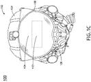
- FIG. 1C is an illustration of the visor 102 incorporated into a helmet 122 (e.g., headgear), in accordance with one or more embodiments of the disclosure.
- the visor 102 is attached to the helmet 124 via the attachment element 108.
- the visor 102 includes the first lens member 104 containing the first viewing area 116, and the second lens member 112 containing the second viewing area 120 (e.g., indicated by the dotted square).
- the visor 102 may also include a third lens member 128 configured as a shield to protect the pilot.
- the third lens member 128 may be tinted or non-tinted.
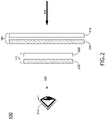
- FIG. 2 is a block diagram illustrating an organization of first lens member 104 and the second lens member 112 at an overlap between the first viewing area 116 and the second viewing area 120, in accordance with one or more embodiments, of the disclosure.
- the first lens member 104 and the second lens member 112 work together to reduce high intensity ambient light 204 to a low intensity ambient light 208 from reaching the user's eye 212.
- the first lens member 104 includes a first transparent shield 216 configured to provide a substrate for photochromic elements and protect the eye/face of the user.
- the first transparent shield 216 may be formed of any transparent or semi-transparent material including but not limited to plastic and glass.
- the first transparent shield 216 may include impact resistant resin.
- the first transparent shield 216 may include an impact resistant polycarbonate resin.
- the first lens member 104 further includes a photochromic layer 220 configured to adjust a first transmission state of the first viewing area based on the transmission of light through the first viewing area 116.
- the photochromic layer 220 may include any type of photochromic material including but not limited to spiropyrans, spirooxanes, diarlethenes, azobenzenes, phorchromic quinones, inorganic photochromics, hexaarylbiimidazole, and photochromic coordination compounds.
- the photochromic layer 220 may be configured to charge the transmissivity of light in as few as three minutes. For example, the photochromic layer 220 may be configured to transition from approximately 30% transmissivity to approximately 90% in approximately two minutes. In another example, the photochromic layer 220 may be configured to transition from approximately 90% transmissivity to approximately 30% in approximately two minutes.
- the photochromic layer 220 may be configured as a separate layer than the first transparent shield 216.
- the photochromic layer 220 may be configured as a coating applied to the first transparent shield 216.
- the photochromic layer 220 may be configured as a solid layer (e.g., plastic layer) embedded with the photochromic material.
- the photochromic layer 220 may also be embedded within, or integrated with, the first transparent shield. Therefore, the above description should not be interpreted as a limitation of the present disclosure, but merely an illustration.
- the second lens member 112 includes a second transparent shield 228 configured to provide a substrate for photochromic elements and/or protect the eye/face of the user.
- the second transparent shield 228 may be formed of any transparent or semi-transparent material including but not limited to plastic and glass.
- the first transparent shield 228 may include impact resistant resin.
- the first transparent shield 228 may include borosilicate glass.
- the second lens member 112 further includes an electrochromic layer 232 configured to adjust a second transmission state of the second viewing area 120 based on a voltage applied to the electrochromic layer 232.
- the electrochromic layer 232 may include any type of electrochromic scheme.
- the electrochromic layer may be configured as a suspended-particle device.
- the electrochromic layer may be configured as a thin laminate of rod-like nano-scale particles suspended in a liquid and placed between two pieces of glass or plastic or attached to one layer. In this instance, the suspended particles are arranged in a light-absorbing, random arrangement when no voltage is applied, then becoming arranged in a light transmitting alignment upon the application of voltage to the system.
- the electrochromic layer 232 may include electrochromic devices that increase opacity in response to an applied voltage.
- the electrochromic layer 232 may be configured as a transition metal hydride electrochromic device.
- the electrochromic layer 232 may be configured as a nano-crystalline film associated with a transparent conductor such as indium tix oxide or poly(3,4-ethylenedioxythiophene) polystyrene sulfonate (PEDOT:PSS), with chromogens that change color by reduction or oxidation.
- the electrochromic layer may be a polymer-dispersed liquid-crystal device (PDLC).
- the electrochromic layer may be configured as a micro-blind.
- the micro-blind may be configured as an array of rolled thin metal blinds that roll upon an applied voltage, altering transmission of light through the electrochromic layer.
- the electrochromic layer 232 may be configured as a separate layer than the second transparent shield 228.
- the electrochromic layer 232 may be configured as a coating or laminate applied to the second transparent shield 228.
- the electrochromic layer 232 may be configured as a solid layer (e.g., glass layer) embedded with the electrochromic material.
- the electrochromic layer 232 may also be embedded within, or integrated with, the second transparent shield 228. Therefore, the above description should not be interpreted as a limitation of the present disclosure, but merely an illustration.
- FIG. 3 is a block diagram illustrating the system 100 in accordance with one or more embodiments of the disclosure.
- the system 100 includes the visor 102 containing the electrochromic layer 232 and the photochromic layer 220.
- the system 100 includes a power source 304 configured to apply a voltage to the electrochromic layer 232.
- the power source 304 may be configured as any power delivery device capable of applying a voltage to the electrochromic layer 232 including but not limited to batteries (e.g., disposable or rechargeable), a capacitor, a voltage relaying conductor (e.g., delivering a voltage from a vehicle power source), and an energy harvesting device (e.g., a solar cell).
- the power source 304 may be disposed within the visor 102, within the headgear, or within the confines of the vehicle.
- the power source 304 may be integrated within an onboard electrical system of the vehicle via an electrical interface.
- the onboard electrical system of the vehicle may be configured to monitor and/or control the voltage of the system 100 via the electrical interface.
- the system includes one or more sensors 312 operatively coupled to the electrochromic layer 232, the photochromic layer 220, the user interface 308, the controller 316, and/or the power source 304.
- one of the one or more sensors may be configured as an ambient light sensor.
- the photochromic layer 220 may be calibrated with the ambient light sensor so that a reading of the ambient light sensor would correspond to the tint of the photochromic layer 220.
- the tint of the electrochromic layer 232 may be calibrated to the ambient light sensor and/or the voltage applied to the electrochromic layer.
- both the photochromic layer 220 and the electrochromic layer 232 are regulated/calibrated based on the ambient light sensor.
- the ambient light sensor and associated controller 316 may be configured to control the overall tint of the system (e.g., the electrochromic layer 232 and the photochromic layer 220) via the voltage control of the electrochromic layer 232.
- the one or more sensors 312 are configured to detect the opacity (e.g., percent transmission) of the electrochromic layer 232 and/or the photochromic layer to the system 100. The system 100 may then adjust the voltage applied to the electrochromic layer so as to adjust the visor 102 to the correct opacity.
- separate sensors 312 may measure the percent transmittance of the electrochromic layer 232 and the photochromic layer 220.
- the system 100 may adjust the voltage applied to the electrochromic layer 232 so that the overall transmittance of the visor 102 is the targeted 50%.
- the ambient light sensor may be communicatively coupled to the electrochromic layer and configured to detect ambient light levels in either an area adjacent to the visor 102 or within a cockpit.
- the ambient light sensor may also be physically coupled to at least one of the visor 102 or the headgear.
- the system 100 may include an electrochromic layer sensor that detects the transmittance adjustment made to the electrochromic layer 232.
- the system may also include a photochromic/electrochromic sensor that measures the transmittance through both the photochromic layer 220 and the electrochromic layer 232.
- one sensor 312 may measure the percent transmittance of both the photochromic layer 220 and the electrochromic layer 232 together (e.g., visor transmittance), with the system 100 configured to adjust the electrochromic layer 232 accordingly. For example, for a system 100 that requires a visor transmittance of 50%, with a sensor 312 currently measuring visor transmittance is at 80% the voltage applied to the electrochromic layer 232 may be adjusted so that the sensor 312 measures a visor transmittance of 50%.
- the system 100 can control the
- the system 100 includes a controller 316 that includes one or more processors 320, a memory 324, and a communication interface 328.
- the controller 316 is configured to provide processing functionality for at least the system 100 and can include the one or more processors 320 (e.g., micro-controllers, circuitry, field programmable gate array (FPGA), central processing units (CPU), application-specific integrated circuit (ASIC), or other processing systems), and resident or external memory 324 for storing data, executable code, and other information.
- the controller 316 can execute one or more software programs embodied in a non-transitory computer readable medium (e.g., memory 324) that implement techniques described herein.
- the controller 316 is not limited by the materials from which it is formed or the processing mechanisms employed therein and, as such, can be implemented via semiconductor(s) and/or transistors (e.g., using electronic integrated circuit (IC) components), and so forth.
- the memory 324 can be an example of tangible, computer-readable storage medium that provides storage functionality to store various data and/or program code associated with operation of the controller 316, such as software programs and/or code segments, or other data to instruct the controller 316, and possibly other components of the system 100, to perform the functionality described herein.
- the memory 324 can store data, such as a program of instructions for operating the system 100, including its components (e.g., controller 316, communication interface 328, etc.), and so forth.
- the memory 324 may also store data derived from the sensor 312. It should be noted that while a single memory 324 is described, a wide variety of types and combinations of memory 324 (e.g., tangible, non-transitory memory) can be employed.
- the memory 324 may be integral with the controller 316, may comprise stand-alone memory, or may be a combination of both. Some examples of the memory 324 may include removable and non-removable memory components, such as random-access memory (RAM), read-only memory (ROM), flash memory (e.g., a secure digital (SD) memory card, a mini-SD memory card, and/or a micro-SD memory card), solid-state drive (SSD) memory, magnetic memory, optical memory, universal serial bus (USB) memory devices, hard disk memory, external memory, and so forth.
- RAM random-access memory
- ROM read-only memory
- flash memory e.g., a secure digital (SD) memory card, a mini-SD memory card, and/or a micro-SD memory card
- SSD solid-state drive
- magnetic memory magnetic memory
- optical memory optical memory
- USB universal serial bus
- the controller 316 may be configured to directly or indirectly adjust the voltage to the electrochromic layer 232.
- the controller 316 may adjust the voltage to the electrochromic layer 232 based on the first transmission state of the photochromic layer 220 (e.g., as measured by the photochromic sensor), enabling the visor 102 to attain a proper transmittance level.
- the controller 316 may adjust the voltage to the electrochromic layer 232 based on a predicted first transmission state of the photochromic layer 220. For instance, the controller 316 may predict the first transmission state of the photochromic layer 220 based on former sensor readings, ambient light measurements, and other parameters, and adjust the voltage to the electrochromic layer 232 based on that prediction.
- the communication interface 328 may be operatively configured to communicate with components of the system 100.
- the communication interface 328 can be configured to retrieve data from the controller 316 or other components, transmit data for storage in the memory 324, retrieve data from storage in the memory 324, and so forth.
- the communication interface 328 can also be communicatively coupled with the controller 316 to facilitate data transfer between components of the system 100 and the controller 316.
- the communication interface 328 is described as a component of the system 100, one or more components of the communication interface 328 can be implemented as external components communicatively coupled to the system 100 via a wired and/or wireless connection.
- the system 100 can also include and/or connect to one or more input/output (I/O) devices.
- the communication interface 328 includes or is coupled to a transmitter, receiver, transceiver, physical connection interface, or any combination thereof.
- FIG. 4 is a drawing illustrating an example environment 400 of the system 100, in accordance with one or more embodiments of the disclosure.
- the example environment 400 includes a first pilot 404 wearing a visor 102 associated with a first pilot helmet 408.
- the user interface 308 associated with the visor 102 of the first pilot 404 is configured as a button associated with an aircraft instrument panel 412.
- the example environment 400 further includes a second pilot 420 wearing a visor 102 associated with a second pilot helmet 424.
- the user interface associate with the visor 102 of the second pilot 420 is configured as a knob 428 located on the second pilot helmet 424.
- embodiments of the methods disclosed herein may include one or more of the steps described herein. Further, such steps may be carried out in any desired order and two or more of the steps may be carried out simultaneously with one another. Two or more of the steps disclosed herein may be combined in a single step, and in some embodiments, one or more of the steps may be carried out as two or more sub-steps. Further, other steps or sub-steps may be carried in addition to, or as substitutes to one or more of the steps disclosed herein.
Landscapes
- Physics & Mathematics (AREA)
- Health & Medical Sciences (AREA)
- Ophthalmology & Optometry (AREA)
- General Physics & Mathematics (AREA)
- Optics & Photonics (AREA)
- Nonlinear Science (AREA)
- General Health & Medical Sciences (AREA)
- Electrochromic Elements, Electrophoresis, Or Variable Reflection Or Absorption Elements (AREA)
Applications Claiming Priority (1)
| Application Number | Priority Date | Filing Date | Title |
|---|---|---|---|
| US17/245,223 US12016420B2 (en) | 2021-04-30 | 2021-04-30 | Combined fast-switch tintable visor |
Publications (2)
| Publication Number | Publication Date |
|---|---|
| EP4083692A1 true EP4083692A1 (de) | 2022-11-02 |
| EP4083692B1 EP4083692B1 (de) | 2024-05-01 |
Family
ID=81326467
Family Applications (1)
| Application Number | Title | Priority Date | Filing Date |
|---|---|---|---|
| EP22168484.8A Active EP4083692B1 (de) | 2021-04-30 | 2022-04-14 | Tönbares und schnell schaltbares visier |
Country Status (2)
| Country | Link |
|---|---|
| US (1) | US12016420B2 (de) |
| EP (1) | EP4083692B1 (de) |
Families Citing this family (1)
| Publication number | Priority date | Publication date | Assignee | Title |
|---|---|---|---|---|
| US11762205B1 (en) * | 2022-09-20 | 2023-09-19 | Rockwell Collins, Inc. | Method for creating uniform contrast on a headworn display against high dynamic range scene |
Citations (3)
| Publication number | Priority date | Publication date | Assignee | Title |
|---|---|---|---|---|
| KR101986192B1 (ko) * | 2017-11-29 | 2019-06-05 | 주식회사 스포컴 | 광 투과율을 조절할 수 있는 아이웨어 |
| US20200018963A1 (en) * | 2018-04-24 | 2020-01-16 | Mentor Acquisition One, Llc | See-through computer display systems with vision correction and increased content density |
| CN112147800A (zh) * | 2020-11-03 | 2020-12-29 | 亿昇(深圳)眼镜科技有限公司 | 智能眼镜 |
Family Cites Families (14)
| Publication number | Priority date | Publication date | Assignee | Title |
|---|---|---|---|---|
| US8023195B2 (en) * | 2008-10-23 | 2011-09-20 | Gentex Corporation | Split laser eye protection system |
| KR102153599B1 (ko) | 2013-11-18 | 2020-09-08 | 삼성전자주식회사 | 머리 착용형 디스플레이 장치 및 머리 착용형 디스플레이 장치의 광 투과율 변경 방법 |
| WO2016077431A2 (en) * | 2014-11-13 | 2016-05-19 | Oakley, Inc. | Variable light attenuation eyewear with color enhancement |
| US10359647B2 (en) | 2015-07-15 | 2019-07-23 | iGlass Technology, Inc. | Wearable electro-optical device using electrochromic layer |
| JP6892213B2 (ja) | 2015-04-30 | 2021-06-23 | ソニーグループ株式会社 | 表示装置及び表示装置の初期設定方法 |
| US20170090194A1 (en) | 2015-09-24 | 2017-03-30 | Halo Augmented Reality Ltd. | System And Method For Subtractive Augmented Reality And Display Contrast Enhancement |
| KR101731928B1 (ko) * | 2015-12-17 | 2017-05-02 | (주)써보레 | 자동차광 보안경 |
| US9880441B1 (en) | 2016-09-08 | 2018-01-30 | Osterhout Group, Inc. | Electrochromic systems for head-worn computer systems |
| US20180188537A1 (en) | 2017-01-04 | 2018-07-05 | Osterhout Group, Inc. | Audio systems for head-worn computers |
| US10522106B2 (en) | 2016-05-05 | 2019-12-31 | Ostendo Technologies, Inc. | Methods and apparatus for active transparency modulation |
| US9910278B1 (en) | 2016-08-31 | 2018-03-06 | Gopro, Inc. | Augmented reality visualization device |
| US11307417B2 (en) | 2017-07-14 | 2022-04-19 | Hewlett-Packard Development Company, L.P. | Panel to attenuate light for electronic eyewear device |
| US10845600B2 (en) | 2018-04-24 | 2020-11-24 | Samsung Electronics Co., Ltd. | Controllable modifiable shader layer for head mountable display |
| CN115039016A (zh) * | 2020-01-31 | 2022-09-09 | 微芯片技术股份有限公司 | 使用电致变色元件的平视显示器 |
-
2021
- 2021-04-30 US US17/245,223 patent/US12016420B2/en active Active
-
2022
- 2022-04-14 EP EP22168484.8A patent/EP4083692B1/de active Active
Patent Citations (3)
| Publication number | Priority date | Publication date | Assignee | Title |
|---|---|---|---|---|
| KR101986192B1 (ko) * | 2017-11-29 | 2019-06-05 | 주식회사 스포컴 | 광 투과율을 조절할 수 있는 아이웨어 |
| US20200018963A1 (en) * | 2018-04-24 | 2020-01-16 | Mentor Acquisition One, Llc | See-through computer display systems with vision correction and increased content density |
| CN112147800A (zh) * | 2020-11-03 | 2020-12-29 | 亿昇(深圳)眼镜科技有限公司 | 智能眼镜 |
Also Published As
| Publication number | Publication date |
|---|---|
| US20220346489A1 (en) | 2022-11-03 |
| EP4083692B1 (de) | 2024-05-01 |
| US12016420B2 (en) | 2024-06-25 |
Similar Documents
| Publication | Publication Date | Title |
|---|---|---|
| US7893890B2 (en) | Electrically dimmable combiner optics for head-up display | |
| US4152846A (en) | Flight training method and apparatus | |
| US9869886B2 (en) | Adaptive spectacles for motor vehicle drivers or passengers | |
| EP2312373B1 (de) | Anzeigegerät mit optischem Fenster mit einstellbarer Transmission | |
| EP0611286B1 (de) | Verfahren und vorrichtung zur steuerung des grades der helligkeitsempfindung mittels einer zeitveränderlichen blende | |
| US20140039730A1 (en) | Systems, methods, and computer readable media for protecting an operator against glare | |
| WO2018006652A1 (zh) | 可调光玻璃、可控遮光装置、方法和车辆 | |
| US9170643B2 (en) | Display system containing an adaptive semi-transparent display device and means for detecting the landscape viewed by the user | |
| CN215705609U (zh) | 车辆设备 | |
| CN103309056A (zh) | 即时自动调光安全镜片装置 | |
| CN110618548B (zh) | 具有动态像素化窗口的系统 | |
| EP4083692B1 (de) | Tönbares und schnell schaltbares visier | |
| US8411214B2 (en) | Variably transmittive, electronically-controlled eyewear | |
| CN105676457A (zh) | 一种多飞行视角的头戴显示设备 | |
| CN112351914A (zh) | 车辆客厢的光标测系统 | |
| EP3816708B1 (de) | Lichtsicherheitsverschluss in der erweiterten realität | |
| EP3715936A1 (de) | Dynamisch getöntes display-visier | |
| CN112305765B (zh) | 光学装置和增强现实显示设备 | |
| CN104297945A (zh) | 实时太阳能感光自动调光安全镜片装置 | |
| JP2016220042A (ja) | 視認装置、視認システム及び建造物の点検方法 | |
| CN110077330A (zh) | 一种车载显示系统 | |
| JP6844216B2 (ja) | 視認システム | |
| US11073707B2 (en) | Dimmable window apparatus and vehicle including the same | |
| US6731253B1 (en) | Ambient adaptable optical combiner | |
| US11435580B1 (en) | High dynamic range head-up display |
Legal Events
| Date | Code | Title | Description |
|---|---|---|---|
| PUAI | Public reference made under article 153(3) epc to a published international application that has entered the european phase |
Free format text: ORIGINAL CODE: 0009012 |
|
| STAA | Information on the status of an ep patent application or granted ep patent |
Free format text: STATUS: THE APPLICATION HAS BEEN PUBLISHED |
|
| AK | Designated contracting states |
Kind code of ref document: A1 Designated state(s): AL AT BE BG CH CY CZ DE DK EE ES FI FR GB GR HR HU IE IS IT LI LT LU LV MC MK MT NL NO PL PT RO RS SE SI SK SM TR |
|
| STAA | Information on the status of an ep patent application or granted ep patent |
Free format text: STATUS: REQUEST FOR EXAMINATION WAS MADE |
|
| 17P | Request for examination filed |
Effective date: 20230427 |
|
| RBV | Designated contracting states (corrected) |
Designated state(s): AL AT BE BG CH CY CZ DE DK EE ES FI FR GB GR HR HU IE IS IT LI LT LU LV MC MK MT NL NO PL PT RO RS SE SI SK SM TR |
|
| GRAP | Despatch of communication of intention to grant a patent |
Free format text: ORIGINAL CODE: EPIDOSNIGR1 |
|
| STAA | Information on the status of an ep patent application or granted ep patent |
Free format text: STATUS: GRANT OF PATENT IS INTENDED |
|
| INTG | Intention to grant announced |
Effective date: 20231206 |
|
| GRAS | Grant fee paid |
Free format text: ORIGINAL CODE: EPIDOSNIGR3 |
|
| GRAA | (expected) grant |
Free format text: ORIGINAL CODE: 0009210 |
|
| STAA | Information on the status of an ep patent application or granted ep patent |
Free format text: STATUS: THE PATENT HAS BEEN GRANTED |
|
| AK | Designated contracting states |
Kind code of ref document: B1 Designated state(s): AL AT BE BG CH CY CZ DE DK EE ES FI FR GB GR HR HU IE IS IT LI LT LU LV MC MK MT NL NO PL PT RO RS SE SI SK SM TR |
|
| REG | Reference to a national code |
Ref country code: GB Ref legal event code: FG4D |
|
| REG | Reference to a national code |
Ref country code: CH Ref legal event code: EP |
|
| REG | Reference to a national code |
Ref country code: DE Ref legal event code: R096 Ref document number: 602022003150 Country of ref document: DE |
|
| REG | Reference to a national code |
Ref country code: IE Ref legal event code: FG4D |
|
| REG | Reference to a national code |
Ref country code: LT Ref legal event code: MG9D |
|
| REG | Reference to a national code |
Ref country code: NL Ref legal event code: MP Effective date: 20240501 |