EP4083377B1 - Verfahren und system zur kriechüberwachung einer turbinenschaufel - Google Patents
Verfahren und system zur kriechüberwachung einer turbinenschaufel Download PDFInfo
- Publication number
- EP4083377B1 EP4083377B1 EP22165908.9A EP22165908A EP4083377B1 EP 4083377 B1 EP4083377 B1 EP 4083377B1 EP 22165908 A EP22165908 A EP 22165908A EP 4083377 B1 EP4083377 B1 EP 4083377B1
- Authority
- EP
- European Patent Office
- Prior art keywords
- blade
- stereo
- borescope
- turbine
- edge
- Prior art date
- Legal status (The legal status is an assumption and is not a legal conclusion. Google has not performed a legal analysis and makes no representation as to the accuracy of the status listed.)
- Active
Links
Images


Classifications
-
- G—PHYSICS
- G06—COMPUTING OR CALCULATING; COUNTING
- G06T—IMAGE DATA PROCESSING OR GENERATION, IN GENERAL
- G06T7/00—Image analysis
- G06T7/0002—Inspection of images, e.g. flaw detection
- G06T7/0004—Industrial image inspection
- G06T7/001—Industrial image inspection using an image reference approach
-
- F—MECHANICAL ENGINEERING; LIGHTING; HEATING; WEAPONS; BLASTING
- F01—MACHINES OR ENGINES IN GENERAL; ENGINE PLANTS IN GENERAL; STEAM ENGINES
- F01D—NON-POSITIVE DISPLACEMENT MACHINES OR ENGINES, e.g. STEAM TURBINES
- F01D5/00—Blades; Blade-carrying members; Heating, heat-insulating, cooling or antivibration means on the blades or the members
- F01D5/005—Repairing methods or devices
-
- F—MECHANICAL ENGINEERING; LIGHTING; HEATING; WEAPONS; BLASTING
- F01—MACHINES OR ENGINES IN GENERAL; ENGINE PLANTS IN GENERAL; STEAM ENGINES
- F01D—NON-POSITIVE DISPLACEMENT MACHINES OR ENGINES, e.g. STEAM TURBINES
- F01D21/00—Shutting-down of machines or engines, e.g. in emergency; Regulating, controlling, or safety means not otherwise provided for
- F01D21/003—Arrangements for testing or measuring
-
- F—MECHANICAL ENGINEERING; LIGHTING; HEATING; WEAPONS; BLASTING
- F01—MACHINES OR ENGINES IN GENERAL; ENGINE PLANTS IN GENERAL; STEAM ENGINES
- F01D—NON-POSITIVE DISPLACEMENT MACHINES OR ENGINES, e.g. STEAM TURBINES
- F01D25/00—Component parts, details, or accessories, not provided for in, or of interest apart from, other groups
- F01D25/28—Supporting or mounting arrangements, e.g. for turbine casing
- F01D25/285—Temporary support structures, e.g. for testing, assembling, installing, repairing; Assembly methods using such structures
-
- F—MECHANICAL ENGINEERING; LIGHTING; HEATING; WEAPONS; BLASTING
- F01—MACHINES OR ENGINES IN GENERAL; ENGINE PLANTS IN GENERAL; STEAM ENGINES
- F01D—NON-POSITIVE DISPLACEMENT MACHINES OR ENGINES, e.g. STEAM TURBINES
- F01D5/00—Blades; Blade-carrying members; Heating, heat-insulating, cooling or antivibration means on the blades or the members
- F01D5/12—Blades
- F01D5/14—Form or construction
-
- G—PHYSICS
- G01—MEASURING; TESTING
- G01B—MEASURING LENGTH, THICKNESS OR SIMILAR LINEAR DIMENSIONS; MEASURING ANGLES; MEASURING AREAS; MEASURING IRREGULARITIES OF SURFACES OR CONTOURS
- G01B11/00—Measuring arrangements characterised by the use of optical techniques
- G01B11/16—Measuring arrangements characterised by the use of optical techniques for measuring the deformation in a solid, e.g. optical strain gauge
-
- G—PHYSICS
- G01—MEASURING; TESTING
- G01N—INVESTIGATING OR ANALYSING MATERIALS BY DETERMINING THEIR CHEMICAL OR PHYSICAL PROPERTIES
- G01N21/00—Investigating or analysing materials by the use of optical means, i.e. using sub-millimetre waves, infrared, visible or ultraviolet light
- G01N21/84—Systems specially adapted for particular applications
- G01N21/88—Investigating the presence of flaws or contamination
- G01N21/95—Investigating the presence of flaws or contamination characterised by the material or shape of the object to be examined
- G01N21/954—Inspecting the inner surface of hollow bodies, e.g. bores
-
- G—PHYSICS
- G02—OPTICS
- G02B—OPTICAL ELEMENTS, SYSTEMS OR APPARATUS
- G02B23/00—Telescopes, e.g. binoculars; Periscopes; Instruments for viewing the inside of hollow bodies; Viewfinders; Optical aiming or sighting devices
- G02B23/24—Instruments or systems for viewing the inside of hollow bodies, e.g. fibrescopes
-
- G—PHYSICS
- G06—COMPUTING OR CALCULATING; COUNTING
- G06T—IMAGE DATA PROCESSING OR GENERATION, IN GENERAL
- G06T7/00—Image analysis
- G06T7/50—Depth or shape recovery
- G06T7/55—Depth or shape recovery from multiple images
- G06T7/593—Depth or shape recovery from multiple images from stereo images
-
- G—PHYSICS
- G06—COMPUTING OR CALCULATING; COUNTING
- G06T—IMAGE DATA PROCESSING OR GENERATION, IN GENERAL
- G06T7/00—Image analysis
- G06T7/80—Analysis of captured images to determine intrinsic or extrinsic camera parameters, i.e. camera calibration
- G06T7/85—Stereo camera calibration
-
- F—MECHANICAL ENGINEERING; LIGHTING; HEATING; WEAPONS; BLASTING
- F05—INDEXING SCHEMES RELATING TO ENGINES OR PUMPS IN VARIOUS SUBCLASSES OF CLASSES F01-F04
- F05D—INDEXING SCHEME FOR ASPECTS RELATING TO NON-POSITIVE-DISPLACEMENT MACHINES OR ENGINES, GAS-TURBINES OR JET-PROPULSION PLANTS
- F05D2220/00—Application
- F05D2220/30—Application in turbines
- F05D2220/32—Application in turbines in gas turbines
- F05D2220/323—Application in turbines in gas turbines for aircraft propulsion, e.g. jet engines
-
- F—MECHANICAL ENGINEERING; LIGHTING; HEATING; WEAPONS; BLASTING
- F05—INDEXING SCHEMES RELATING TO ENGINES OR PUMPS IN VARIOUS SUBCLASSES OF CLASSES F01-F04
- F05D—INDEXING SCHEME FOR ASPECTS RELATING TO NON-POSITIVE-DISPLACEMENT MACHINES OR ENGINES, GAS-TURBINES OR JET-PROPULSION PLANTS
- F05D2230/00—Manufacture
- F05D2230/80—Repairing, retrofitting or upgrading methods
-
- F—MECHANICAL ENGINEERING; LIGHTING; HEATING; WEAPONS; BLASTING
- F05—INDEXING SCHEMES RELATING TO ENGINES OR PUMPS IN VARIOUS SUBCLASSES OF CLASSES F01-F04
- F05D—INDEXING SCHEME FOR ASPECTS RELATING TO NON-POSITIVE-DISPLACEMENT MACHINES OR ENGINES, GAS-TURBINES OR JET-PROPULSION PLANTS
- F05D2240/00—Components
- F05D2240/20—Rotors
- F05D2240/30—Characteristics of rotor blades, i.e. of any element transforming dynamic fluid energy to or from rotational energy and being attached to a rotor
-
- F—MECHANICAL ENGINEERING; LIGHTING; HEATING; WEAPONS; BLASTING
- F05—INDEXING SCHEMES RELATING TO ENGINES OR PUMPS IN VARIOUS SUBCLASSES OF CLASSES F01-F04
- F05D—INDEXING SCHEME FOR ASPECTS RELATING TO NON-POSITIVE-DISPLACEMENT MACHINES OR ENGINES, GAS-TURBINES OR JET-PROPULSION PLANTS
- F05D2260/00—Function
- F05D2260/80—Diagnostics
-
- F—MECHANICAL ENGINEERING; LIGHTING; HEATING; WEAPONS; BLASTING
- F05—INDEXING SCHEMES RELATING TO ENGINES OR PUMPS IN VARIOUS SUBCLASSES OF CLASSES F01-F04
- F05D—INDEXING SCHEME FOR ASPECTS RELATING TO NON-POSITIVE-DISPLACEMENT MACHINES OR ENGINES, GAS-TURBINES OR JET-PROPULSION PLANTS
- F05D2260/00—Function
- F05D2260/83—Testing, e.g. methods, components or tools therefor
-
- F—MECHANICAL ENGINEERING; LIGHTING; HEATING; WEAPONS; BLASTING
- F05—INDEXING SCHEMES RELATING TO ENGINES OR PUMPS IN VARIOUS SUBCLASSES OF CLASSES F01-F04
- F05D—INDEXING SCHEME FOR ASPECTS RELATING TO NON-POSITIVE-DISPLACEMENT MACHINES OR ENGINES, GAS-TURBINES OR JET-PROPULSION PLANTS
- F05D2270/00—Control
- F05D2270/30—Control parameters, e.g. input parameters
-
- G—PHYSICS
- G01—MEASURING; TESTING
- G01B—MEASURING LENGTH, THICKNESS OR SIMILAR LINEAR DIMENSIONS; MEASURING ANGLES; MEASURING AREAS; MEASURING IRREGULARITIES OF SURFACES OR CONTOURS
- G01B11/00—Measuring arrangements characterised by the use of optical techniques
- G01B11/24—Measuring arrangements characterised by the use of optical techniques for measuring contours or curvatures
-
- G—PHYSICS
- G06—COMPUTING OR CALCULATING; COUNTING
- G06T—IMAGE DATA PROCESSING OR GENERATION, IN GENERAL
- G06T2207/00—Indexing scheme for image analysis or image enhancement
- G06T2207/10—Image acquisition modality
- G06T2207/10016—Video; Image sequence
- G06T2207/10021—Stereoscopic video; Stereoscopic image sequence
Definitions
- the present disclosure relates to a method and a system for monitoring turbine blade creep in a gas turbine engine.
- borescopes are used to view internal components within an assembled gas turbine engine to determine if the components within the engine are damaged and need repair or if they are undamaged and do not require repair.
- the use of borescopes enables the components to be viewed without having to disassemble the gas turbine engine into modules or sub modules.
- the current approach for on-wing assessment of turbine blade creep is to use a borescope to visually estimate the radial growth of a blade with a borescope by observing the size of the gap between a shroud of the blade and a liner forming the outer wall of the working annulus of the engine.
- Metrical (i.e. quantitative) measurement is currently performed by stripping down the engine and precisely measuring the dimensions of the top of the blade using a coordinate measurement machine (CMM). This is time-consuming and expensive, and can only be performed when the engine is in a maintenance facility with the necessary equipment.
- CMM coordinate measurement machine
- EP 3330692 A1 describes systems and methods for evaluating component strain, and monitoring creep in turbine blades by measurement of a reference (passive strain) indicator and comparison with a replicate of the reference indicator.
- DE 10 2019 100821 A1 discloses a horoscope for optical inspection of gas turbines.
- the method can be performed on-wing and without stripping down the engine.
- Turbine blades are currently used for a conservative number of operation cycles. More accurate determination of turbine blade creep allows for the turbine blades to be used for a longer duration, reducing operating costs.
- the landmarks are respectively on a platform and a shroud of the turbine blade. A measured distance between such landmarks is highly sensitive to creep-induced lengthening of the blade.
- the reference distance is the distance between the radially inner and radially outer landmarks for a turbine blade which has not experienced creep.
- this reference distance may be determined by measuring an actual blade or by extracting the distance information from a 3D model (e.g. a CAD model or a scan data model) of the blade.
- the receiving, identifying, mapping, measuring and comparing may be performed for each of successive turbine blades of the row of turbine blades.
- the method of the first aspect can be used to monitor all the turbine blades of the row for creep.
- the method may further include: calibrating the stereo borescope to determine imaging distortions produced thereby; and using the calibration to adjust the images to remove or reduce imaging distortions before the mapping onto the 3D space.
- the stereo borescope may be used to obtain a stereo video of the turbine blade as the row of turbine blades rotates, the stereo images being stills extracted from the stereo video.
- the identifying may include performing automated image analysis to extract feature lines of each of the stereo images.
- the extracted lines can be the trailing edge line, one or more platform edge lines, one or more shroud edge lines from each of the images and/or one or more seal segment edge lines. This can help to remove a source of operator variation.
- the image analysis may perform image filtering as a precursor to extracting the edge lines of the blade.
- the method may further include, preliminary to receiving the image of a turbine blade: locating the stereo borescope in the engine adjacent the row of turbine blades; and using the stereo borescope to obtain the stereo images of the turbine blade of the row of turbine blades.
- Locating the borescope in the engine may comprise inserting the borescope into a port on an accessible part of the engine. Guiding the borescope through a guide tunnel until the end of the borescope is at the end of the guide tunnel.
- the system of the second aspect corresponds to the method of the first aspect.
- the landmarks are respectively on a platform and a shroud of the turbine blade.
- the reference distance is the nominal distance between the radially inner and radially outer landmarks for a turbine blade which has not experienced creep.
- the processor-based sub-system may be further adapted to: calibrate the stereo borescope to determine imaging distortions produced thereby; and use the calibration to adjust the images to remove or reduce imaging distortions before the mapping onto the 3D space.
- the system may further include a stereo borescope adapted to be located in the engine adjacent the row of turbine blades for obtaining the stereo images of the turbine blade of the row of turbine blades, the computer readable medium being operatively connectable to the borescope to receive therefrom the images of the turbine blade.
- the stereo borescope may be adapted to obtain a stereo video of the turbine blade as the row of turbine blades rotates, the stereo images being stills extracted from the stereo video.
- the processor-based sub-system by further adapted to: perform automated image analysis to extract feature lines of each of the stereo images.
- the extracted lines can be the trailing edge line, one or more platform edge lines, one or more shroud edge lines from each of the images and/or one or more seal segment edge lines.
- the image analysis may perform image filtering as a precursor to extracting the edge lines of the blade.
- the method of the first or second aspect is typically computer-implemented. Accordingly, further aspects of the disclosure provide: a computer program comprising code which, when the code is executed on a computer, causes the computer to perform the method of the first or second aspect; and a computer readable medium storing a computer program comprising code which, when the code is executed on a computer, causes the computer to perform the method of the first or second aspect.
- All of the aspects may map identified features into a 3D space. They may then compare the mapped features to a reference model to determine the amount of creep or distortion of a turbine blade.
- a ducted fan gas turbine engine for an aircraft is generally indicated at 10 and has a principal and rotational axis X-X.
- the engine comprises, in axial flow series, an air intake 11, a propulsive fan 12, an intermediate pressure compressor 13, a high-pressure compressor 14, combustion equipment 15, a high-pressure turbine 16, an intermediate pressure turbine 17, a low-pressure turbine 18 and a core engine exhaust nozzle 19.
- a nacelle 21 generally surrounds the engine 10 and defines the intake 11, a bypass duct 22 and a bypass exhaust nozzle 23.
- air entering the intake 11 is accelerated by the fan 12 to produce two air flows: a first air flow A into the intermediate-pressure compressor 13 and a second air flow B which passes through the bypass duct 22 to provide propulsive thrust.
- the intermediate-pressure compressor 13 compresses the air flow A directed into it before delivering that air to the high-pressure compressor 14 where further compression takes place.
- the compressed air exhausted from the high-pressure compressor 14 is directed into the combustion equipment 15 where it is mixed with fuel and the mixture combusted.
- the resultant hot combustion products then expand through, and thereby drive the high, intermediate and low-pressure turbines 16, 17, 18 before being exhausted through the nozzle 19 to provide additional propulsive thrust.
- the high, intermediate and low-pressure turbines respectively drive the high and intermediate-pressure compressors 14, 13 and the fan 12 by suitable interconnecting shafts.
- aircraft gas turbine engines to which the present disclosure may be applied may have alternative configurations.
- such engines may have an alternative number of interconnecting shafts (e.g. two) and/or an alternative number of compressors and/or turbines.
- the engine may comprise a gearbox provided in the drive train from a turbine to a compressor and/or fan.
- the borescope can be calibrated to determine any imaging distortions which it produces.
- Various calibration procedures are known to the skilled person, such as described for example by Zhengyou Zhang, A Flexible New Technique for Camera Calibration, Technical Report MSR-TR-98-71, https://www.microsoft.com/en-us/research/wp-content/uploads/2017/02/tr98-71.pdf .
- the calibration can then be used to adjust images obtained by the borescope to remove or reduce imaging distortions.
- the stereo borescope is located adjacent a row of blades to obtain stereo images of part of the row.
- the row is then rotated so that each blade in turn is moved into position relative to the borescope.
- This can be achieved by indexing the rotational position of the row, or more conveniently by using the borescope to obtain a stereo video of the row as it continuously rotates.
- Respective stereo stills can then be extracted from the video for each of the blades, each still corresponding to its blade being in a given position relative to the borescope.
- Figure 2 shows a pair of left and right stereo stills for a blade.
- a processor-based image analyser performs edge detection on each image.
- the image analyser may perform image filtering (e.g. noising filtering, texture filtering, compression-less filtering etc.) to enhance the images.
- image filtering e.g. noising filtering, texture filtering, compression-less filtering etc.
- edges corresponding to the trailing edge of the blade 34, an edge 30 of the platform of the blade, and an edge 32 of the shroud of the blade are detected by the image analyser (e.g. using template matching, edge detection, textural analysis etc.) and the lines of these edges extracted.
- the image analyser may ensure that the trailing edge 34 is in a defined region of interest (rectangles R in Figure 2 ), whereby the image analyser can confirm that the blade is appropriately positioned relative to the stereo borescope. This may further improve the identification of features.
- the same features are identified in both images of the stereo pair.
- the same identification algorithm may be applied to each image of the stereopair.
- features may be identified in one image and epipolar triangulation used to roughly locate a reduced region where an identification algorithm can be applied on the second image. The latter may reduce computation requirements.
- the image analyser then moves on to a 3D analysis. In particular, it takes the stereo images, and maps the features by triangulation onto a 3D space to produce a 3D depth map of the blade. Suitable triangulation techniques are known to the skilled person. See for example: https://users.cecs.anu.edu.au/ ⁇ hartley/Papers/CVPR99-tutorial/tutorial.pdf
- landmarks are identified in the 3D space map, such as a radially inner landmark 36 which is the corner of the platform edge 30 closest to the trailing edge 34, and a radially outer landmark 38 which is the corner of the shroud edge 32 closest to the trailing edge 34.
- the distance D between these two landmarks in the 3D space map is then determined.
- the image analyser compares the measured distance D with a reference distance to determine an amount of creep-induced lengthening of the blade.
- the reference distance is the corresponding distance for a turbine blade which has not experienced creep. This can be obtained by measuring an actual blade before service, or by extracting the distance information from a 3D model of the blade. By using two landmarks on the turbine blade, only distortion of the turbine blade is measured, and not for example, relative movement between the turbine blade and an external reference point.
- Figure 3 summarises stages of this creep monitoring procedure.
- the accuracy of the measurement is improved. That is, any measurement of change in length due to creep is increased relative to approaches which do not use the whole length.
- the distance measurement can be obtained with high reproducibility and accuracy.
- using features identified in a 2D analysis as the basis for the 3D measurements simplifies and saves computational power.
- the 2D analysis helps to filter out erroneous features before the 3D measurement, and requiring that the same features are identified in the two stereo images enforces consistency.
- the method can also be repeated for further stereo images with the blade changing position slightly (due to rotation) between each image capture to further improve accuracy.
- An average of the measurements may be determined for comparison with the reference distance.
- an advantage of building a full or partial 3D depth map of the blade is that more complex shape deviations of the blade can be measured.
- comparing such a depth map to a 3D reference model e.g. a CAD model in the form of a 3D point cloud
- a 3D reference model e.g. a CAD model in the form of a 3D point cloud
- Twisting in particular is difficult to measure using conventional approaches to borescope measurement.
- Elongation and twisting of a turbine blade both deformations which can limit blade service life.
- a partial 3D depth map is a map of just the platform and shroud of the blade. Deviation of the shroud position (e.g. due to blade elongation and/or twisting) relative to the platform position can then be used to monitor for creep.
- This approach requires less computation than building up an entire 3D model of the blade for comparison with the reference model. Instead, only parts of the shroud and platform observable by the stereo borescope need to be mapped onto 3D space to produce a depth map.
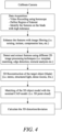
- Figure 4 summarises stages of this more elaborate creep monitoring procedure.
- An example of the comparison of a 3D depth map with a 3D reference model may comprise registering both models at the platform, then performing a Procrustes analysis, iterative closest points algorithm, normal closest points transform or similar to return the best fit or average deviation of one model from the other.
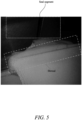
- the stereo borescope is used to image a seal segment located radially outwardly of the blades.
- Figure 5 shows a borescope image of a seal segment adjacent a blade shroud.
- the amount of distortion can also be determined by measuring relative twisting between a shroud and a seal segment when the blade is at a predetermined rotational position relative to the segment.
- the stereo images capture the shroud and the seal segment
- the image analyser identifies features of the shroud and the seal segment, and maps them onto the 3D space.
- the 3D reference model also has to include the seal segment.
- Elongation of a turbine blade can also be determined by measuring the distance between the seal segment and the shroud of the turbine blade.
- elongation and/or rotation of the shroud may be identified by first identifying in 3D space a plane associated with the seal segment and a plane associated with the shroud. The distance between and/or relative angles of these planes may then be compared to the same of a 3D reference model. The seal segment and the shroud are close together, which means a smaller field of view can be used; this may allow the stereo borescope to be positioned closer to the turbine blade for further improved accuracy.
- An unclaimed example of landmarks on the blade that can be monitored using the above approach are cooling holes on the blade (in particular at the leading edge). Measuring their positions allows a surface strain map of the blade to be produced, i.e. in a manner similar to strain extensometry. For example, the distance between each of the cooling holes may be compared to a 3D reference model and regions on the turbine blade where deformation has occurred may be identified.
- any of the preceding comparison methods may be used in combination.
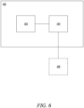
- FIG. 6 shows a system 100 according to aspects.
- the system 100 comprises a computer readable storage medium 104 for storing I.A. stereo images or video received from a stereo borescope 106.
- the system 100 also comprises a processor-based sub-system 102.
- the processor-based sub-system 102 is operationally connected to the computer readable storage medium.
- the operational connection between the processor-based sub-system 102 and the computer readable storage medium 104 may enable the processor-based sub-system to access stereo images stored on the computer readable storage medium 104 and optionally a 3D reference model stored on the computer readable storage medium.
- the processor-based sub-system 102 is adapted to perform the method of the first aspect.
- the processor-based sub-system 102 may is adapted to identify the trailing edge 34, platform edge 30 and shroud edge 32 of the blade in each of the stereo images; map each of the trailing edge 34, platform edge 30 and shroud edge 32by triangulation onto a 3D space; measure in the 3D space a distance (D) between a radially inner landmark 36 at the corner of the platform edge 30 closest to the trailing edge 34 on the blade, and a radially outer landmark(38) at the corner of the shroud edge 32 closest to the trailing edge (34) on the blade; and compare the distance (D) with the distance between the radially inner and radially outer landmarks for a turbine blade which has not experienced creep to determine an amount of creep-induced distortion of the blade.
- the system may comprise a stereo borescope 106 shown in figure 6 in a dashed line.
- the computer readable medium may be operatively connected to the stereo borescope to receive the stereo images and/or video of the turbine blade from the stereo borescope 106.
- control of the stereo borescope 106 may be performed by the processor-based sub-system 102.
- the stereo borescope 106 may be adapted to be located in the engine adjacent the row of turbine blades for obtaining the stereo images and/or video of the turbine blade of the row of turbine blades.
- the stereo video of the turbine blade may be captured as a row of turbine blades rotates.
- the processor-based sub-system 102 may be adapted to extract and analyse still stereo images from the video stored on the computer readable storage medium 104.
Landscapes
- Engineering & Computer Science (AREA)
- Physics & Mathematics (AREA)
- General Physics & Mathematics (AREA)
- Mechanical Engineering (AREA)
- General Engineering & Computer Science (AREA)
- Computer Vision & Pattern Recognition (AREA)
- Theoretical Computer Science (AREA)
- Quality & Reliability (AREA)
- Chemical & Material Sciences (AREA)
- Life Sciences & Earth Sciences (AREA)
- Health & Medical Sciences (AREA)
- Analytical Chemistry (AREA)
- Biochemistry (AREA)
- General Health & Medical Sciences (AREA)
- Immunology (AREA)
- Pathology (AREA)
- Astronomy & Astrophysics (AREA)
- Optics & Photonics (AREA)
- Length Measuring Devices By Optical Means (AREA)
- Testing Of Devices, Machine Parts, Or Other Structures Thereof (AREA)
Claims (8)
- Verfahren zur Überwachung eines Kriechens einer Turbinenschaufel in einem Gasturbinentriebwerk (10), wobei das Verfahren beinhaltet:Empfangen von Stereo-Bildern einer Turbinenschaufel einer Reihe von Turbinenschaufeln, wobei die Stereo-Bilder die gesamte radiale Länge der Schaufel abdecken und unter Verwendung eines Stereo-Endoskops erhalten worden sind, das im Triebwerk neben der Reihe von Turbinenschaufeln platziert ist;Identifizieren einer Hinterkante (34), einer Plattformkante (30) und einer Abdeckungskante (32) des Schaufel in jedem der Stereo-Bilder;Abbilden der Hinterkante (34), der Plattformkante (30) und der Abdeckungskante (32) jeweils durch Triangulation auf einen 3D-Raum;Messen eines Abstands (D) im 3D-Raum zwischen einem radial inneren Orientierungspunkt (36) an der Ecke der Plattformkante (30), die der Hinterkante (34) an der Schaufel am nächsten liegt, und einem radial äußeren Orientierungspunkt (38) an der Ecke der Abdeckungskante (32), die der Hinterkante (34) an der Schaufel am nächsten liegt; undVergleichen des gemessenen Abstands (D) mit dem Abstand zwischen den radial inneren (36) und radial äußeren (38) Orientierungspunkten für eine Turbinenschaufel, bei der kein Kriechen aufgetreten ist, um ein Ausmaß der durch das Kriechen verursachten Verformung der Schaufel zu bestimmen.
- Verfahren nach einem der vorhergehenden Ansprüche, ferner beinhaltend:Kalibrieren des Stereo-Endoskops, um dadurch erzeugte Bildverzerrungen zu bestimmen; undVerwenden der Kalibrierung zum Anpassen der Bilder, um Bildverzerrungen vor der Abbildung auf den 3D-Raum zu entfernen oder zu reduzieren.
- Verfahren nach einem der vorhergehenden Ansprüche, ferner beinhaltend, vor dem Empfangen des Bildes einer Turbinenschaufel:
Platzieren des Stereo-Endoskops im Triebwerk neben der Reihe von Turbinenschaufeln; und Verwenden des Endoskops zum Erhalten eines Bilds der Turbinenschaufel der Reihe von Turbinenschaufeln. - Verfahren nach einem der vorhergehenden Ansprüche, wobei das Stereo-Endoskop verwendet wird, um ein Stereo-Video der Turbinenschaufel zu erhalten, während sich die Reihe von Turbinenschaufeln dreht, wobei die Stereo-Bilder aus dem Video extrahierte Standbilder sind.
- System (100) zur Überwachung eines Kriechens einer Turbinenschaufel in einem Gasturbinentriebwerk, wobei das System beinhaltet:ein computerlesbares Medium (104) zum Speichern von Stereo-Bildern einer Turbinenschaufel einer Reihe von Turbinenschaufeln, wobei die Stereo-Bilder die gesamte radiale Länge der Schaufel abdecken und unter Verwendung eines Stereo-Endoskops (106) erhalten worden sind, das im Triebwerk neben der Reihe von Turbinenschaufeln platziert ist; undein prozessorbasiertes Teilsystem (102), das funktionell mit dem computerlesbaren Medium verbunden ist und angepasst ist zum:Identifizieren einer Hinterkante (34), einer Plattformkante (30) und einer Abdeckungskante (32) der Schaufel in jedem der Stereo-Bilder;Abbilden der Hinterkante (34), der Plattformkante (30) und der Abdeckungskante (32) jeweils durch Triangulation auf einen 3D-Raum;Messen eines Abstands (D) im 3D-Raum zwischen einem radial inneren Orientierungspunkt (36) an der Ecke der Plattformkante (30), die der Hinterkante (34) an der Schaufel am nächsten liegt, und einem radial äußeren Orientierungspunkt (38) an der Ecke der Abdeckungskante (32), die der Hinterkante (34) an der Schaufel am nächsten liegt; undVergleichen des gemessenen Abstands (D) mit dem Abstand zwischen den radial inneren (36) und radial äußeren (38) Orientierungspunkten für eine Turbinenschaufel, bei der kein Kriechen aufgetreten ist, um ein Ausmaß der durch das Kriechen verursachten Verformung der Schaufel zu bestimmen.
- System nach Anspruch 5, ferner beinhaltend ein Stereo-Endoskop, das dazu angepasst ist, in dem Triebwerk neben der Reihe von Turbinenschaufeln platziert zu werden, um die Stereo-Bilder der Turbinenschaufel der Reihe von Turbinenschaufeln zu erhalten, wobei das computerlesbare Medium funktionell mit dem Stereo-Endoskop verbindbar ist, um von diesem die Bilder der Turbinenschaufel zu empfangen.
- System nach einem der Ansprüche 5 oder 6, wobei das Stereo-Endoskop dazu angepasst ist, ein Stereo-Video der Turbinenschaufel zu erhalten, während sich die Reihe von Turbinenschaufeln dreht, wobei die Stereo-Bilder aus dem Video extrahierte Standbilder sind.
- System nach einem der Ansprüche 5, 6 oder 7, wobei das prozessorbasierte Teilsystem ferner angepasst sein kann zum: Kalibrieren des Stereo-Endoskops, um dadurch erzeugte Bildverzerrungen zu bestimmen; und Verwenden der Kalibrierung, um die Bilder anzupassen, um Bildverzerrungen vor der Abbildung auf den 3D-Raum zu entfernen oder zu reduzieren.
Priority Applications (1)
| Application Number | Priority Date | Filing Date | Title |
|---|---|---|---|
| EP24203650.7A EP4462073A3 (de) | 2021-04-29 | 2022-03-31 | Verfahren und system zur überwachung des kriechens einer turbinenschaufel |
Applications Claiming Priority (1)
| Application Number | Priority Date | Filing Date | Title |
|---|---|---|---|
| GBGB2106109.8A GB202106109D0 (en) | 2021-04-29 | 2021-04-29 | Turbine blade creep monitoring |
Related Child Applications (2)
| Application Number | Title | Priority Date | Filing Date |
|---|---|---|---|
| EP24203650.7A Division-Into EP4462073A3 (de) | 2021-04-29 | 2022-03-31 | Verfahren und system zur überwachung des kriechens einer turbinenschaufel |
| EP24203650.7A Division EP4462073A3 (de) | 2021-04-29 | 2022-03-31 | Verfahren und system zur überwachung des kriechens einer turbinenschaufel |
Publications (3)
| Publication Number | Publication Date |
|---|---|
| EP4083377A2 EP4083377A2 (de) | 2022-11-02 |
| EP4083377A3 EP4083377A3 (de) | 2022-11-09 |
| EP4083377B1 true EP4083377B1 (de) | 2024-11-27 |
Family
ID=76301133
Family Applications (2)
| Application Number | Title | Priority Date | Filing Date |
|---|---|---|---|
| EP24203650.7A Pending EP4462073A3 (de) | 2021-04-29 | 2022-03-31 | Verfahren und system zur überwachung des kriechens einer turbinenschaufel |
| EP22165908.9A Active EP4083377B1 (de) | 2021-04-29 | 2022-03-31 | Verfahren und system zur kriechüberwachung einer turbinenschaufel |
Family Applications Before (1)
| Application Number | Title | Priority Date | Filing Date |
|---|---|---|---|
| EP24203650.7A Pending EP4462073A3 (de) | 2021-04-29 | 2022-03-31 | Verfahren und system zur überwachung des kriechens einer turbinenschaufel |
Country Status (3)
| Country | Link |
|---|---|
| US (1) | US12223640B2 (de) |
| EP (2) | EP4462073A3 (de) |
| GB (1) | GB202106109D0 (de) |
Families Citing this family (1)
| Publication number | Priority date | Publication date | Assignee | Title |
|---|---|---|---|---|
| US12049832B2 (en) | 2022-12-28 | 2024-07-30 | Ge Infrastructure Technology Llc | Cooling hole positioning systems and methods |
Family Cites Families (26)
| Publication number | Priority date | Publication date | Assignee | Title |
|---|---|---|---|---|
| AU2305792A (en) | 1991-06-26 | 1993-01-25 | John C. Lafeber | Dual lens borescope measurement device |
| JP2994987B2 (ja) | 1995-05-16 | 1999-12-27 | 三菱重工業株式会社 | 回転体の連続映像撮影装置 |
| US8107083B2 (en) | 2008-03-05 | 2012-01-31 | General Electric Company | System aspects for a probe system that utilizes structured-light |
| US7810385B1 (en) | 2008-08-20 | 2010-10-12 | Florida Turbine Technologies, Inc. | Process for determining a remaining creep life for a turbine component |
| US8157504B2 (en) | 2009-04-17 | 2012-04-17 | General Electric Company | Rotor blades for turbine engines |
| DE102010017749A1 (de) | 2010-07-05 | 2012-01-05 | Ssb Wind Systems Gmbh & Co. Kg | Vorrichtung zur optischen Messung der Biegung eines Rotorblatts einer Windkraftanlage |
| FR2975771B1 (fr) | 2011-05-27 | 2014-03-14 | Snecma | Dispositif de mesure d'une piece dans une turbomachine |
| DE102011114541A1 (de) * | 2011-09-30 | 2013-04-04 | Lufthansa Technik Ag | Endoskopiesystem und korrespondierendesVerfahren zur Untersuchung von Gasturbinen |
| US8818078B2 (en) | 2012-02-03 | 2014-08-26 | Solar Turbines Inc. | Apparatus and method for optically measuring creep |
| US9581438B2 (en) | 2012-12-31 | 2017-02-28 | General Electric Company | Systems and methods for control of a non-destructive testing system |
| JP2015078895A (ja) | 2013-10-17 | 2015-04-23 | 三菱日立パワーシステムズ株式会社 | 腐食ピット検査方法 |
| US9476798B2 (en) | 2014-02-21 | 2016-10-25 | General Electric Company | On-line monitoring of hot gas path components of a gas turbine |
| US9618334B2 (en) | 2015-04-15 | 2017-04-11 | General Electric Company | Systems and methods for monitoring turbine component strain |
| US20170138820A1 (en) | 2015-11-16 | 2017-05-18 | General Electric Company | Systems and methods for monitoring components |
| US20170358073A1 (en) | 2015-11-16 | 2017-12-14 | General Electric Company | Systems and Methods for Monitoring Components |
| US9953408B2 (en) | 2015-11-16 | 2018-04-24 | General Electric Company | Methods for monitoring components |
| US20170148152A1 (en) | 2015-11-25 | 2017-05-25 | General Electric Company | Systems and Methods for Monitoring Component Strain |
| US9967523B2 (en) * | 2015-12-16 | 2018-05-08 | General Electric Company | Locating systems and methods for components |
| US10024760B2 (en) | 2015-12-17 | 2018-07-17 | General Electric Company | Methods for monitoring turbine components |
| US10557372B2 (en) | 2015-12-17 | 2020-02-11 | General Electric Company | Systems and methods for assessing strain of components in turbomachines |
| GB2554687B (en) | 2016-10-04 | 2020-02-12 | Rolls Royce Plc | Computer implemented methods for determining a dimension of a gap between an aerofoil and a surface of an engine casing |
| US9879981B1 (en) | 2016-12-02 | 2018-01-30 | General Electric Company | Systems and methods for evaluating component strain |
| US20180209781A1 (en) | 2017-01-23 | 2018-07-26 | General Electric Company | Method of Making a Component with an Integral Strain Indicator |
| US10666927B2 (en) | 2017-03-15 | 2020-05-26 | Baker Hughes, A Ge Company, Llc | Method and device for inspection of an asset |
| US10451499B2 (en) | 2017-04-06 | 2019-10-22 | General Electric Company | Methods for applying passive strain indicators to components |
| DE102019100821A1 (de) * | 2019-01-14 | 2020-07-16 | Lufthansa Technik Aktiengesellschaft | Boroskop zur optischen Inspektion von Gasturbinen |
-
2021
- 2021-04-29 GB GBGB2106109.8A patent/GB202106109D0/en not_active Ceased
-
2022
- 2022-03-31 EP EP24203650.7A patent/EP4462073A3/de active Pending
- 2022-03-31 EP EP22165908.9A patent/EP4083377B1/de active Active
- 2022-04-04 US US17/712,676 patent/US12223640B2/en active Active
Also Published As
| Publication number | Publication date |
|---|---|
| EP4462073A2 (de) | 2024-11-13 |
| US12223640B2 (en) | 2025-02-11 |
| EP4462073A3 (de) | 2025-01-01 |
| EP4083377A2 (de) | 2022-11-02 |
| EP4083377A3 (de) | 2022-11-09 |
| GB202106109D0 (en) | 2021-06-16 |
| US20220351352A1 (en) | 2022-11-03 |
Similar Documents
| Publication | Publication Date | Title |
|---|---|---|
| CN103842621B (zh) | 用于检查气涡轮机的内窥镜系统和相应方法 | |
| EP3623788B1 (de) | Automatisiertes notrangordnungssystem | |
| US12345167B2 (en) | System and method of using a tool assembly | |
| US7337058B1 (en) | Engine wear characterizing and quantifying method | |
| CN106969734A (zh) | 用于构件的定位系统及方法 | |
| US8903692B2 (en) | Method for the detection of failures in a turbomachine by means of a theoretical model of the thermodynamic cycle of the said turbomachine | |
| EP4083376B1 (de) | Kriechüberwachung einer turbinenschaufel | |
| CN113034599A (zh) | 一种航空发动机的孔探检测装置和方法 | |
| EP4083377B1 (de) | Verfahren und system zur kriechüberwachung einer turbinenschaufel | |
| US20200049564A1 (en) | Systems and methods for thermal imaging systems | |
| US20250191163A1 (en) | Analysing images of components | |
| EP4425425A2 (de) | Inspektion von teilen unter verwendung geometrischer modelle | |
| CN119885479B (zh) | 一种基于叶片表面关键点法向量夹角变化的气路性能评估方法 | |
| EP4528638A1 (de) | Inspektionssysteme und -verfahren zur schadensmessung | |
| CN223650403U (zh) | 一种航空发动机高压涡轮叶片全自动检查装置 | |
| EP4163871A1 (de) | Inspektion des inneren einer gasturbinenmotorvorrichtung | |
| CN116309252A (zh) | 一种航空发动机转子孔探视频的智能分析方法 | |
| HK1200893B (en) | Endoscopy system and corresponding method for examining gas turbines |
Legal Events
| Date | Code | Title | Description |
|---|---|---|---|
| PUAI | Public reference made under article 153(3) epc to a published international application that has entered the european phase |
Free format text: ORIGINAL CODE: 0009012 |
|
| STAA | Information on the status of an ep patent application or granted ep patent |
Free format text: STATUS: THE APPLICATION HAS BEEN PUBLISHED |
|
| PUAL | Search report despatched |
Free format text: ORIGINAL CODE: 0009013 |
|
| AK | Designated contracting states |
Kind code of ref document: A2 Designated state(s): AL AT BE BG CH CY CZ DE DK EE ES FI FR GB GR HR HU IE IS IT LI LT LU LV MC MK MT NL NO PL PT RO RS SE SI SK SM TR |
|
| AK | Designated contracting states |
Kind code of ref document: A3 Designated state(s): AL AT BE BG CH CY CZ DE DK EE ES FI FR GB GR HR HU IE IS IT LI LT LU LV MC MK MT NL NO PL PT RO RS SE SI SK SM TR |
|
| RIC1 | Information provided on ipc code assigned before grant |
Ipc: G01B 21/04 20060101ALI20221004BHEP Ipc: G01B 11/16 20060101ALI20221004BHEP Ipc: F01D 25/28 20060101ALI20221004BHEP Ipc: F01D 21/00 20060101ALI20221004BHEP Ipc: F01D 5/00 20060101AFI20221004BHEP |
|
| STAA | Information on the status of an ep patent application or granted ep patent |
Free format text: STATUS: REQUEST FOR EXAMINATION WAS MADE |
|
| 17P | Request for examination filed |
Effective date: 20230425 |
|
| RBV | Designated contracting states (corrected) |
Designated state(s): AL AT BE BG CH CY CZ DE DK EE ES FI FR GB GR HR HU IE IS IT LI LT LU LV MC MK MT NL NO PL PT RO RS SE SI SK SM TR |
|
| REG | Reference to a national code |
Ref country code: DE Ref legal event code: R079 Ref document number: 602022008060 Country of ref document: DE Free format text: PREVIOUS MAIN CLASS: F01D0005000000 Ipc: G01B0011240000 |
|
| RIC1 | Information provided on ipc code assigned before grant |
Ipc: G01B 11/16 20060101ALI20240701BHEP Ipc: F01D 25/28 20060101ALI20240701BHEP Ipc: F01D 21/00 20060101ALI20240701BHEP Ipc: F01D 5/00 20060101ALI20240701BHEP Ipc: G02B 23/24 20060101ALI20240701BHEP Ipc: G01N 21/954 20060101ALI20240701BHEP Ipc: G01B 11/24 20060101AFI20240701BHEP |
|
| GRAP | Despatch of communication of intention to grant a patent |
Free format text: ORIGINAL CODE: EPIDOSNIGR1 |
|
| STAA | Information on the status of an ep patent application or granted ep patent |
Free format text: STATUS: GRANT OF PATENT IS INTENDED |
|
| GRAS | Grant fee paid |
Free format text: ORIGINAL CODE: EPIDOSNIGR3 |
|
| GRAA | (expected) grant |
Free format text: ORIGINAL CODE: 0009210 |
|
| STAA | Information on the status of an ep patent application or granted ep patent |
Free format text: STATUS: THE PATENT HAS BEEN GRANTED |
|
| INTG | Intention to grant announced |
Effective date: 20240930 |
|
| P01 | Opt-out of the competence of the unified patent court (upc) registered |
Free format text: CASE NUMBER: APP_55505/2024 Effective date: 20241009 |
|
| AK | Designated contracting states |
Kind code of ref document: B1 Designated state(s): AL AT BE BG CH CY CZ DE DK EE ES FI FR GB GR HR HU IE IS IT LI LT LU LV MC MK MT NL NO PL PT RO RS SE SI SK SM TR |
|
| REG | Reference to a national code |
Ref country code: GB Ref legal event code: FG4D |
|
| REG | Reference to a national code |
Ref country code: CH Ref legal event code: EP |
|
| REG | Reference to a national code |
Ref country code: DE Ref legal event code: R096 Ref document number: 602022008060 Country of ref document: DE |
|
| REG | Reference to a national code |
Ref country code: IE Ref legal event code: FG4D |
|
| REG | Reference to a national code |
Ref country code: LT Ref legal event code: MG9D |
|
| REG | Reference to a national code |
Ref country code: NL Ref legal event code: MP Effective date: 20241127 |
|
| PG25 | Lapsed in a contracting state [announced via postgrant information from national office to epo] |
Ref country code: HR Free format text: LAPSE BECAUSE OF FAILURE TO SUBMIT A TRANSLATION OF THE DESCRIPTION OR TO PAY THE FEE WITHIN THE PRESCRIBED TIME-LIMIT Effective date: 20241127 Ref country code: IS Free format text: LAPSE BECAUSE OF FAILURE TO SUBMIT A TRANSLATION OF THE DESCRIPTION OR TO PAY THE FEE WITHIN THE PRESCRIBED TIME-LIMIT Effective date: 20250327 Ref country code: PT Free format text: LAPSE BECAUSE OF FAILURE TO SUBMIT A TRANSLATION OF THE DESCRIPTION OR TO PAY THE FEE WITHIN THE PRESCRIBED TIME-LIMIT Effective date: 20250327 |
|
| PG25 | Lapsed in a contracting state [announced via postgrant information from national office to epo] |
Ref country code: NL Free format text: LAPSE BECAUSE OF FAILURE TO SUBMIT A TRANSLATION OF THE DESCRIPTION OR TO PAY THE FEE WITHIN THE PRESCRIBED TIME-LIMIT Effective date: 20241127 Ref country code: FI Free format text: LAPSE BECAUSE OF FAILURE TO SUBMIT A TRANSLATION OF THE DESCRIPTION OR TO PAY THE FEE WITHIN THE PRESCRIBED TIME-LIMIT Effective date: 20241127 |
|
| REG | Reference to a national code |
Ref country code: AT Ref legal event code: MK05 Ref document number: 1746071 Country of ref document: AT Kind code of ref document: T Effective date: 20241127 |
|
| PG25 | Lapsed in a contracting state [announced via postgrant information from national office to epo] |
Ref country code: BG Free format text: LAPSE BECAUSE OF FAILURE TO SUBMIT A TRANSLATION OF THE DESCRIPTION OR TO PAY THE FEE WITHIN THE PRESCRIBED TIME-LIMIT Effective date: 20241127 |
|
| PG25 | Lapsed in a contracting state [announced via postgrant information from national office to epo] |
Ref country code: ES Free format text: LAPSE BECAUSE OF FAILURE TO SUBMIT A TRANSLATION OF THE DESCRIPTION OR TO PAY THE FEE WITHIN THE PRESCRIBED TIME-LIMIT Effective date: 20241127 |
|
| PG25 | Lapsed in a contracting state [announced via postgrant information from national office to epo] |
Ref country code: NO Free format text: LAPSE BECAUSE OF FAILURE TO SUBMIT A TRANSLATION OF THE DESCRIPTION OR TO PAY THE FEE WITHIN THE PRESCRIBED TIME-LIMIT Effective date: 20250227 |
|
| PG25 | Lapsed in a contracting state [announced via postgrant information from national office to epo] |
Ref country code: LV Free format text: LAPSE BECAUSE OF FAILURE TO SUBMIT A TRANSLATION OF THE DESCRIPTION OR TO PAY THE FEE WITHIN THE PRESCRIBED TIME-LIMIT Effective date: 20241127 Ref country code: AT Free format text: LAPSE BECAUSE OF FAILURE TO SUBMIT A TRANSLATION OF THE DESCRIPTION OR TO PAY THE FEE WITHIN THE PRESCRIBED TIME-LIMIT Effective date: 20241127 Ref country code: GR Free format text: LAPSE BECAUSE OF FAILURE TO SUBMIT A TRANSLATION OF THE DESCRIPTION OR TO PAY THE FEE WITHIN THE PRESCRIBED TIME-LIMIT Effective date: 20250228 |
|
| PG25 | Lapsed in a contracting state [announced via postgrant information from national office to epo] |
Ref country code: PL Free format text: LAPSE BECAUSE OF FAILURE TO SUBMIT A TRANSLATION OF THE DESCRIPTION OR TO PAY THE FEE WITHIN THE PRESCRIBED TIME-LIMIT Effective date: 20241127 |
|
| PG25 | Lapsed in a contracting state [announced via postgrant information from national office to epo] |
Ref country code: RS Free format text: LAPSE BECAUSE OF FAILURE TO SUBMIT A TRANSLATION OF THE DESCRIPTION OR TO PAY THE FEE WITHIN THE PRESCRIBED TIME-LIMIT Effective date: 20250227 |
|
| PG25 | Lapsed in a contracting state [announced via postgrant information from national office to epo] |
Ref country code: SM Free format text: LAPSE BECAUSE OF FAILURE TO SUBMIT A TRANSLATION OF THE DESCRIPTION OR TO PAY THE FEE WITHIN THE PRESCRIBED TIME-LIMIT Effective date: 20241127 |
|
| PG25 | Lapsed in a contracting state [announced via postgrant information from national office to epo] |
Ref country code: DK Free format text: LAPSE BECAUSE OF FAILURE TO SUBMIT A TRANSLATION OF THE DESCRIPTION OR TO PAY THE FEE WITHIN THE PRESCRIBED TIME-LIMIT Effective date: 20241127 |
|
| PG25 | Lapsed in a contracting state [announced via postgrant information from national office to epo] |
Ref country code: EE Free format text: LAPSE BECAUSE OF FAILURE TO SUBMIT A TRANSLATION OF THE DESCRIPTION OR TO PAY THE FEE WITHIN THE PRESCRIBED TIME-LIMIT Effective date: 20241127 |
|
| PG25 | Lapsed in a contracting state [announced via postgrant information from national office to epo] |
Ref country code: RO Free format text: LAPSE BECAUSE OF FAILURE TO SUBMIT A TRANSLATION OF THE DESCRIPTION OR TO PAY THE FEE WITHIN THE PRESCRIBED TIME-LIMIT Effective date: 20241127 |
|
| PG25 | Lapsed in a contracting state [announced via postgrant information from national office to epo] |
Ref country code: SK Free format text: LAPSE BECAUSE OF FAILURE TO SUBMIT A TRANSLATION OF THE DESCRIPTION OR TO PAY THE FEE WITHIN THE PRESCRIBED TIME-LIMIT Effective date: 20241127 |
|
| PG25 | Lapsed in a contracting state [announced via postgrant information from national office to epo] |
Ref country code: CZ Free format text: LAPSE BECAUSE OF FAILURE TO SUBMIT A TRANSLATION OF THE DESCRIPTION OR TO PAY THE FEE WITHIN THE PRESCRIBED TIME-LIMIT Effective date: 20241127 |
|
| PG25 | Lapsed in a contracting state [announced via postgrant information from national office to epo] |
Ref country code: IT Free format text: LAPSE BECAUSE OF FAILURE TO SUBMIT A TRANSLATION OF THE DESCRIPTION OR TO PAY THE FEE WITHIN THE PRESCRIBED TIME-LIMIT Effective date: 20241127 |
|
| REG | Reference to a national code |
Ref country code: DE Ref legal event code: R097 Ref document number: 602022008060 Country of ref document: DE |
|
| PG25 | Lapsed in a contracting state [announced via postgrant information from national office to epo] |
Ref country code: SE Free format text: LAPSE BECAUSE OF FAILURE TO SUBMIT A TRANSLATION OF THE DESCRIPTION OR TO PAY THE FEE WITHIN THE PRESCRIBED TIME-LIMIT Effective date: 20241127 |
|
| PLBE | No opposition filed within time limit |
Free format text: ORIGINAL CODE: 0009261 |
|
| STAA | Information on the status of an ep patent application or granted ep patent |
Free format text: STATUS: NO OPPOSITION FILED WITHIN TIME LIMIT |
|
| REG | Reference to a national code |
Ref country code: CH Ref legal event code: L10 Free format text: ST27 STATUS EVENT CODE: U-0-0-L10-L00 (AS PROVIDED BY THE NATIONAL OFFICE) Effective date: 20251008 |
|
| PG25 | Lapsed in a contracting state [announced via postgrant information from national office to epo] |
Ref country code: MC Free format text: LAPSE BECAUSE OF FAILURE TO SUBMIT A TRANSLATION OF THE DESCRIPTION OR TO PAY THE FEE WITHIN THE PRESCRIBED TIME-LIMIT Effective date: 20241127 |
|
| REG | Reference to a national code |
Ref country code: CH Ref legal event code: H13 Free format text: ST27 STATUS EVENT CODE: U-0-0-H10-H13 (AS PROVIDED BY THE NATIONAL OFFICE) Effective date: 20251024 |
|
| 26N | No opposition filed |
Effective date: 20250828 |
|
| PG25 | Lapsed in a contracting state [announced via postgrant information from national office to epo] |
Ref country code: LU Free format text: LAPSE BECAUSE OF NON-PAYMENT OF DUE FEES Effective date: 20250331 |
|
| REG | Reference to a national code |
Ref country code: BE Ref legal event code: MM Effective date: 20250331 |
|
| PG25 | Lapsed in a contracting state [announced via postgrant information from national office to epo] |
Ref country code: BE Free format text: LAPSE BECAUSE OF NON-PAYMENT OF DUE FEES Effective date: 20250331 |
|
| PG25 | Lapsed in a contracting state [announced via postgrant information from national office to epo] |
Ref country code: CH Free format text: LAPSE BECAUSE OF NON-PAYMENT OF DUE FEES Effective date: 20250331 |
|
| PG25 | Lapsed in a contracting state [announced via postgrant information from national office to epo] |
Ref country code: IE Free format text: LAPSE BECAUSE OF NON-PAYMENT OF DUE FEES Effective date: 20250331 |
|
| PGFP | Annual fee paid to national office [announced via postgrant information from national office to epo] |
Ref country code: GB Payment date: 20260323 Year of fee payment: 5 |
|
| PGFP | Annual fee paid to national office [announced via postgrant information from national office to epo] |
Ref country code: DE Payment date: 20260320 Year of fee payment: 5 |
|
| PGFP | Annual fee paid to national office [announced via postgrant information from national office to epo] |
Ref country code: FR Payment date: 20260323 Year of fee payment: 5 |