EP4083376B1 - Kriechüberwachung einer turbinenschaufel - Google Patents
Kriechüberwachung einer turbinenschaufel Download PDFInfo
- Publication number
- EP4083376B1 EP4083376B1 EP22165907.1A EP22165907A EP4083376B1 EP 4083376 B1 EP4083376 B1 EP 4083376B1 EP 22165907 A EP22165907 A EP 22165907A EP 4083376 B1 EP4083376 B1 EP 4083376B1
- Authority
- EP
- European Patent Office
- Prior art keywords
- image
- turbine blade
- distance
- blade
- turbine
- Prior art date
- Legal status (The legal status is an assumption and is not a legal conclusion. Google has not performed a legal analysis and makes no representation as to the accuracy of the status listed.)
- Active
Links
Images
Classifications
-
- G—PHYSICS
- G06—COMPUTING OR CALCULATING; COUNTING
- G06T—IMAGE DATA PROCESSING OR GENERATION, IN GENERAL
- G06T7/00—Image analysis
- G06T7/0002—Inspection of images, e.g. flaw detection
- G06T7/0004—Industrial image inspection
- G06T7/001—Industrial image inspection using an image reference approach
-
- G—PHYSICS
- G01—MEASURING; TESTING
- G01M—TESTING STATIC OR DYNAMIC BALANCE OF MACHINES OR STRUCTURES; TESTING OF STRUCTURES OR APPARATUS, NOT OTHERWISE PROVIDED FOR
- G01M15/00—Testing of engines
- G01M15/14—Testing gas-turbine engines or jet-propulsion engines
-
- G—PHYSICS
- G01—MEASURING; TESTING
- G01M—TESTING STATIC OR DYNAMIC BALANCE OF MACHINES OR STRUCTURES; TESTING OF STRUCTURES OR APPARATUS, NOT OTHERWISE PROVIDED FOR
- G01M5/00—Investigating the elasticity of structures, e.g. deflection of bridges or air-craft wings
- G01M5/0016—Investigating the elasticity of structures, e.g. deflection of bridges or air-craft wings of aircraft wings or blades
-
- G—PHYSICS
- G01—MEASURING; TESTING
- G01M—TESTING STATIC OR DYNAMIC BALANCE OF MACHINES OR STRUCTURES; TESTING OF STRUCTURES OR APPARATUS, NOT OTHERWISE PROVIDED FOR
- G01M5/00—Investigating the elasticity of structures, e.g. deflection of bridges or air-craft wings
- G01M5/0041—Investigating the elasticity of structures, e.g. deflection of bridges or air-craft wings by determining deflection or stress
-
- F—MECHANICAL ENGINEERING; LIGHTING; HEATING; WEAPONS; BLASTING
- F01—MACHINES OR ENGINES IN GENERAL; ENGINE PLANTS IN GENERAL; STEAM ENGINES
- F01D—NON-POSITIVE DISPLACEMENT MACHINES OR ENGINES, e.g. STEAM TURBINES
- F01D21/00—Shutting-down of machines or engines, e.g. in emergency; Regulating, controlling, or safety means not otherwise provided for
- F01D21/003—Arrangements for testing or measuring
-
- F—MECHANICAL ENGINEERING; LIGHTING; HEATING; WEAPONS; BLASTING
- F01—MACHINES OR ENGINES IN GENERAL; ENGINE PLANTS IN GENERAL; STEAM ENGINES
- F01D—NON-POSITIVE DISPLACEMENT MACHINES OR ENGINES, e.g. STEAM TURBINES
- F01D5/00—Blades; Blade-carrying members; Heating, heat-insulating, cooling or antivibration means on the blades or the members
- F01D5/005—Repairing methods or devices
-
- F—MECHANICAL ENGINEERING; LIGHTING; HEATING; WEAPONS; BLASTING
- F05—INDEXING SCHEMES RELATING TO ENGINES OR PUMPS IN VARIOUS SUBCLASSES OF CLASSES F01-F04
- F05D—INDEXING SCHEME FOR ASPECTS RELATING TO NON-POSITIVE-DISPLACEMENT MACHINES OR ENGINES, GAS-TURBINES OR JET-PROPULSION PLANTS
- F05D2260/00—Function
- F05D2260/80—Diagnostics
-
- F—MECHANICAL ENGINEERING; LIGHTING; HEATING; WEAPONS; BLASTING
- F05—INDEXING SCHEMES RELATING TO ENGINES OR PUMPS IN VARIOUS SUBCLASSES OF CLASSES F01-F04
- F05D—INDEXING SCHEME FOR ASPECTS RELATING TO NON-POSITIVE-DISPLACEMENT MACHINES OR ENGINES, GAS-TURBINES OR JET-PROPULSION PLANTS
- F05D2270/00—Control
- F05D2270/80—Devices generating input signals, e.g. transducers, sensors, cameras or strain gauges
- F05D2270/804—Optical devices
- F05D2270/8041—Cameras
-
- G—PHYSICS
- G06—COMPUTING OR CALCULATING; COUNTING
- G06T—IMAGE DATA PROCESSING OR GENERATION, IN GENERAL
- G06T2207/00—Indexing scheme for image analysis or image enhancement
- G06T2207/30—Subject of image; Context of image processing
- G06T2207/30108—Industrial image inspection
Definitions
- the present disclosure relates to a method and a system for monitoring turbine blade creep in a gas turbine engine.
- borescopes are used to view internal components within an assembled gas turbine engine to determine if the components within the engine are damaged and need repair or if they are undamaged and do not require repair.
- the use of borescopes enables the components to be viewed without having to disassemble the gas turbine engine into modules or sub modules.
- the current approach for on-wing assessment of turbine blade creep is to use a borescope to visually estimate the radial growth of a blade with a borescope by observing the size of the gap between a shroud of the blade and a liner forming the outer wall of the working annulus of the engine.
- US2017358073 relates to systems and methods for monitoring components.
- a component has an exterior surface.
- a method includes performing a first analysis of a first image of a surface feature configured on the exterior surface of the component, the first image obtained by an imaging device.
- the method further includes adjusting a viewing parameter of the imaging device when a predetermined first analysis threshold for the first image is unsatisfied, and performing a subsequent first analysis of a second image of the surface feature, the second image obtained by the imaging device.
- the method further includes adjusting a distance between the imaging device and the surface feature when the predetermined first analysis threshold for the second image is unsatisfied, and performing a second analysis of a third image, the third image obtained by the imaging device.
- US2017138820 relates to systems and methods for monitoring components.
- a component has an exterior surface and a surface feature configured on the component.
- a system includes a data acquisition device for analyzing the surface feature.
- the system further includes an alignment assembly for aligning the data acquisition device and the surface feature.
- the alignment assembly includes a target feature configurable on the component and a guide feature configured with the data acquisition device. Alignment of the guide feature with the target feature aligns the data acquisition device and the surface feature.
- the present disclosure is at least partly based on a realisation that a measurement distance derived from a borescope image can be sufficiently repeatable and accurate to reliably monitor creep-induced lengthening of the blade. Moreover, the method can be performed on-wing and without stripping down the engine. Thus, it facilitates consistent and relatively frequent measurements from which creep growth in different cycling stages and on different parts of the blade can be understood.
- the measurement on the image of the distance between the radially inner and radially outer landmarks on the turbine blade may include: identifying on the image, or a corresponding image, a feature of the turbine blade having a known size; determining a distance conversion scale using the known size of the identified feature; and using the conversion scale to determine the distance between the radially inner and radially outer landmarks.
- the feature can be a spacing of known distance between two air film cooling holes formed in the blade.
- the feature can be a superficial marking or discolouration blemish of known size.
- the borescope may be a conventional borescope or a stereo borescope which is used to obtain left and right images, the measuring being performed for each of the left and right images. This can improve the accuracy of and increase the confidence in the determination of creep-induced lengthening.
- the measuring may be performed plural times for different images of the blade (e.g. left and right images and/or different stills of a video of the turbine blade as the row of turbine blades rotates).
- the measurements can then provide an average measured distance for comparison with the reference distance.
- the reference distance may be the distance between the radially inner and radially outer landmarks for a turbine blade which has not experienced creep. For example, this reference distance may be determined by measuring an actual blade or by extracting the distance information from a 3D model (e.g. a CAD model or a scan data model) of the blade.
- a 3D model e.g. a CAD model or a scan data model
- the measuring may include performing automated image analysis to extract edge lines of the turbine blade from the image.
- the extracted lines can be the trailing edge line, one or more platform edge lines and/or one or more shroud edge lines from the image. This can facilitate the measurement of the distance between the radially inner and radially outer landmarks, and can help to remove a source of operator variation.
- the image analysis may perform image filtering as a precursor to extracting the edge lines of the blade.
- the receiving, measuring and comparing may be performed for each of successive turbine blades of the row of turbine blades.
- the method can be used to monitor all the turbine blades of the row for creep.
- the method may further include: calibrating the borescope to determine imaging distortions produced thereby; and using the calibration to adjust the image to remove or reduce imaging distortions before the measurement on the image of the distance between radially inner and radially outer landmarks on the turbine blade.
- the method may further include, preliminary to receiving the image of a turbine blade: locating the borescope in the engine adjacent the row of turbine blades; and using the borescope to obtain the image of the turbine blade of the row of turbine blades.
- Locating the borescope in the engine may comprise inserting the borescope into a port on an accessible part of the engine. Guiding the borescope through a guide tunnel until the end of the borescope is at the end of the guide tunnel.
- the borescope and/or guide tube may be shaped or comprise fitments to improve the reproducibility of positioning the borescope.
- the system of the second aspect corresponds to the method of the first aspect.
- the measurement on the image of the distance between radially inner and radially outer landmarks on the turbine blade performed by the automated image analysis may include: identifying on the image, or a corresponding image, a feature of the turbine blade having a known size; determining a distance conversion scale using the known size of the identified feature; and using the conversion scale to determine the distance between the radially inner and radially outer landmarks.
- the borescope may be a stereo borescope which is used to obtain left and right images, the measuring and comparing being performed for each of the left and right images.
- the reference distance may be the distance between the radially inner and radially outer landmarks for a turbine blade which has not experienced creep.
- the processor-based sub-system may be further adapted to extract edge lines of the turbine blade from the image, e.g. as a precursor to measuring the distance between the radially inner and radially outer landmarks.
- the processor-based sub-system may be further adapted to perform image filtering as a precursor to extracting the edge lines.
- the processor-based sub-system may be further adapted to: calibrate the borescope to determine imaging distortions produced thereby; and use the calibration to adjust the image to remove or reduce imaging distortions before performing the automated image analysis.
- the system may further include a borescope adapted to be located in the engine adjacent the row of turbine blades for obtaining the image of the turbine blade of the row of turbine blades, the computer readable medium being operatively connectable to the borescope to receive therefrom the image of the turbine blade.
- the borescope may be adapted to obtain a video of the turbine blade as the row of turbine blades rotates, the image being a still image extracted from the video.
- the method of the first aspect is typically computer-implemented. Accordingly, further aspects of the disclosure provide: a computer program comprising code which, when the code is executed on a computer, causes the computer to perform the method of the first aspect; and a computer readable medium storing a computer program comprising code which, when the code is executed on a computer, causes the computer to perform the method of the first aspect.
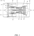
- a ducted fan gas turbine engine is generally indicated at 10 and has a principal and rotational axis X-X.
- the engine comprises, in axial flow series, an air intake 11, a propulsive fan 12, an intermediate pressure compressor 13, a high-pressure compressor 14, combustion equipment 15, a high-pressure turbine 16, an intermediate pressure turbine 17, a low-pressure turbine 18 and a core engine exhaust nozzle 19.
- a nacelle 21 generally surrounds the engine 10 and defines the intake 11, a bypass duct 22 and a bypass exhaust nozzle 23.
- air entering the intake 11 is accelerated by the fan 12 to produce two air flows: a first air flow A into the intermediate-pressure compressor 13 and a second air flow B which passes through the bypass duct 22 to provide propulsive thrust.
- the intermediate-pressure compressor 13 compresses the air flow A directed into it before delivering that air to the high-pressure compressor 14 where further compression takes place.
- the compressed air exhausted from the high-pressure compressor 14 is directed into the combustion equipment 15 where it is mixed with fuel and the mixture combusted.
- the resultant hot combustion products then expand through, and thereby drive the high, intermediate and low-pressure turbines 16, 17, 18 before being exhausted through the nozzle 19 to provide additional propulsive thrust.
- the high, intermediate and low-pressure turbines respectively drive the high and intermediate-pressure compressors 14, 13 and the fan 12 by suitable interconnecting shafts.
- gas turbine engines to which the present disclosure may be applied may have alternative configurations.
- such engines may have an alternative number of interconnecting shafts (e.g. two) and/or an alternative number of compressors and/or turbines.
- the engine may comprise a gearbox provided in the drive train from a turbine to a compressor and/or fan.
- the borescope can be calibrated to determine any imaging distortions which it produces.
- Various calibration procedures are known to the skilled person, such as described for example by Zhengyou Zhang, A Flexible New Technique for Camera Calibration, Technical Report MSR-TR-98-71, https://www.microsoft.com/en-us/research/wp-content/uploads/2017/02/tr98-71.pdf.
- the calibration can then be used to adjust images obtained by the borescope to remove or reduce imaging distortions.
- the borescope is located adjacent a row of blades to obtain an image of part of the row.
- the row is then rotated so that each blade in turn is moved into position to be imaged by the borescope. This can be achieved by indexing the rotational position of the row, or more conveniently by using the borescope to obtain a video of the row as it continuously rotates. Respective stills can then be extracted from the video for the blades, each still corresponding to its blade being in a given position relative to the borescope.
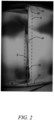
- Figure 2 shows one such still for a blade.
- Borescopes conventionally have distance measuring capability. This can be used directly to measure distances on the image. However, particularly for larger scale measurements beyond the normal measuring range of borescopes, better accuracies can be obtained by determining a distance conversion scale, for example in pixels/mm, based on features of known size. For example, the spacings between air film cooling holes formed in the blade are generally known to high accuracy and can be used to determine such a scale. Another option is to measure the length of a superficial marking or discolouration blemish of known size (as determined e.g. by a coordinate measuring machine), such as marking 40 at the trailing edge 34 of the blade shown in Figure 2 , and using that to determine the scale.
- a superficial marking or discolouration blemish of known size as determined e.g. by a coordinate measuring machine
- the scale determined for the image of one blade can be applied without loss of significant accuracy to corresponding images of other blades.
- a processor-based image analyser performs edge detection on each image.
- the image analyser may perform image filtering (e.g. noising filtering, texture filtering, compression-less filtering etc.) to enhance the images.
- the image analyser may, for example, perform canny edge detection to identify edge in the image, the image analyser may then perform a Hough transformation to reject unwanted lines.
- edges corresponding to the trailing edge of the blade 34, an edge 30 of the platform of the blade, and an edge 32 of the shroud of the blade are then detected by the image analyser (e.g. using template matching, edge detection, textural analysis etc.) and the lines of these edges extracted.
- the image analyser may ensure that the trailing edge 34 is in a defined region of interest (rectangle R in Figure 2 ), whereby the image analyser can confirm that the blade is appropriately positioned relative to the borescope prior to distance measurement. This may further improve accuracy of edge detection by further improving reproducibility of lighting of the turbine blade.
- the image analyser then identifies two landmarks. These are indicated on Figure 2 as a radially inner landmark 36 which is the corner of the platform edge 30 closest to the trailing edge 34, and a radially outer landmark 38 which is the corner of the shroud edge 32 closest to the trailing edge 34.
- the distance D between these two landmarks is determined either by applying a conversion scale to convert from pixels to actual distance.
- the conversion scale may be determined by direct measurement by the borescope, or indirectly by measuring a known distance between two features on the borescope images e.g. between two cooling holes. Accurate measurement between two visible features (e.g. cooling holes, surface defects) may be made by the borescope at a position close to the turbine blade.
- the conversion may be applied to the distance D between the two landmarks which is taken at a larger field of view.
- the image analyser compares the measured distance D with a reference distance to determine an amount of creep-induced lengthening of the blade.
- the reference distance is typically the corresponding distance for a turbine blade which has not experienced creep. This can be obtained by measuring an actual blade, or by extracting the distance information from a 3D model of the blade.
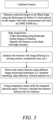
- Figure 3 summarises stages of the creep monitoring procedure.
- the accuracy of the measurement is improved. That is, any measurement of change in length due to creep is increased relative to approaches which do not use the whole length.
- the borescope is a stereo borescope
- simultaneous left and right images can be obtained of each blade to double the number of distance measurements from each still.
- Table 1 shows example distance measurement results for left and right images of a blade obtained using a stereo borescope for six successive stills with the blade changing position slightly (due to rotation) between each still.
- Table 1 Left Right Still 1 61.0 mm 61.1 mm Still 2 61.2 mm 60.7 mm Still 3 60.9 mm 60.9 mm Still 4 61.1 mm 61.2 mm Still 5 60.9 mm 61.0 mm Still 6 60.9 mm -
- An average of the measurements may be determined for comparison with the reference distance.
- using left and right stereo images provides a useful check on edge detection and landmark identification.
- no distance measurement was made for the right image because the image analyser was unable to extract and identify one or both of the landmarks.
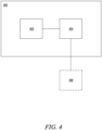
- FIG. 4 shows a system 100 according to an aspect.
- the system 100 comprises a computer readable storage medium 104 for storing I.A. stereo images received from a borescope 106.
- the system 100 also comprises a processor-based sub-system 102.
- the processor-based sub-system 102 is operationally connected to the computer readable storage medium.
- the operational connection between the processor-based sub-system 102 and the computer readable storage medium 104 may enable the processor-based sub-system to access images or video stored on the computer readable storage medium 104 and optionally a 3D reference model stored on the computer readable storage medium.
- the processor-based sub-system 102 may be adapted to perform the methods disclosed herein.
- the processor-based sub-system 102 may be adapted to receive an image of a turbine blade of a row of turbine blades, the image having been obtained using a borescope located in the engine adjacent a row of turbine blades.
- the processor-based sub-system 102 may measure on the image a distance (D) between radially inner and radially outer landmarks (36, 38) on the turbine blade; and may compare the measured distance with a reference distance to determine an amount of creep-induced lengthening of the blade.
- the system may comprise a borescope 106 shown in figure 4 in a dashed line.
- the computer readable medium may be operatively connected to the borescope to receive the images and/or video of the turbine blade from the borescope 106.
- control of the borescope 106 may be performed by the processor-based sub-system 102.
- the borescope 106 may be adapted to be located in the engine adjacent the row of turbine blades for obtaining the images and/or video of the turbine blade of the row of turbine blades.
- the video of the turbine blade may be captured as a row of turbine blades rotates.
- the processor-based sub-system 102 may be adapted to extract and analyse still images from the video stored on the computer readable storage medium 104.
- the processor-based sub-system 102 may be adapted to extract edge lines (30, 32, 34) of the turbine blade from the image as a precursor to measuring the distance between the radially inner and radially outer landmarks.
- the processor-based sub-system 102 may be adapted to identify landmarks on the turbine blade wherein the landmarks are respectively on a platform and a shroud of the turbine blade.
- the processor-based sub-system 102 may be adapted to identify on an image, or a corresponding image, a feature (40) of the turbine blade having a known size; and to determine therefrom a distance conversion scale; and using the conversion scale to determine the distance between the radially inner and radially outer landmarks.
- the processor-based sub-system 102 may be adapted to calibrate the borescope to determine imaging distortions produced thereby; and to use the calibration to adjust an image to remove or reduce imaging distortions before the measurement on the image of the distance between radially inner and radially outer landmarks on the turbine blade.
- Embodiments may be described as a process which is depicted as a flowchart, a flow diagram, a data flow diagram, a structure diagram, or a block diagram. Although a flowchart may describe the operations as a sequential process, many of the operations can be performed in parallel or concurrently. In addition, the order of the operations may be rearranged. A process is terminated when its operations are completed but could have additional steps not included in the figure. A process may correspond to a method, a function, a procedure, a subroutine, a subprogram, etc. When a process corresponds to a function, its termination corresponds to a return of the function to the calling function or the main function.
- computer readable medium may represent one or more devices for storing data, including read only memory (ROM), random access memory (RAM), magnetic RAM, core memory, magnetic disk storage mediums, optical storage mediums, flash memory devices and/or other machine-readable mediums for storing information.
- ROM read only memory
- RAM random access memory
- magnetic RAM magnetic RAM
- core memory magnetic disk storage mediums
- optical storage mediums flash memory devices and/or other machine-readable mediums for storing information.
- computer-readable medium includes but is not limited to portable or fixed storage devices, optical storage devices, wireless channels and various other mediums capable of storing, containing or carrying instruction(s) and/or data.
- embodiments may be implemented by hardware, software, firmware, middleware, microcode, hardware description languages, or any combination thereof.
- the program code or code segments to perform the necessary tasks may be stored in a computer readable medium.
- One or more processors may perform the necessary tasks.
- a code segment may represent a procedure, a function, a subprogram, a program, a routine, a subroutine, a module, a software package, a class, or any combination of instructions, data structures, or program statements.
- a code segment may be coupled to another code segment or a hardware circuit by passing and/or receiving information, data, arguments, parameters, or memory contents. Information, arguments, parameters, data, etc. may be passed, forwarded, or transmitted via any suitable means including memory sharing, message passing, token passing, network transmission, etc.
Landscapes
- Engineering & Computer Science (AREA)
- Physics & Mathematics (AREA)
- General Physics & Mathematics (AREA)
- Aviation & Aerospace Engineering (AREA)
- Mechanical Engineering (AREA)
- General Engineering & Computer Science (AREA)
- Quality & Reliability (AREA)
- Computer Vision & Pattern Recognition (AREA)
- Theoretical Computer Science (AREA)
- Chemical & Material Sciences (AREA)
- Combustion & Propulsion (AREA)
- Length Measuring Devices By Optical Means (AREA)
Claims (13)
- Verfahren zum Überwachen eines Kriechens einer Turbinenschaufel in einem Gasturbinentriebwerk, wobei das Verfahren Folgendes beinhaltet:Empfangen eines Bildes einer Turbinenschaufel einer Reihe von Turbinenschaufeln, wobei das Bild unter Verwendung eines Endoskops erhalten wurde, das in dem Triebwerk benachbart zu einer Reihe von Turbinenschaufeln lokalisiert ist;Messen einer Entfernung (D) zwischen einem radial inneren und radial äußeren Orientierungspunkt (36, 38) an der Turbinenschaufel auf dem Bild; undVergleichen der gemessenen Entfernung mit einer Referenzentfernung, um den Betrag der durch Kriechen verursachten Verlängerung der Schaufel zu bestimmen, dadurch gekennzeichnet, dass sich die Orientierungspunkte jeweils auf einer Plattform und einer Abdeckung der Turbinenschaufel befinden, und wobei jeder Orientierungspunkt eine Ecke der jeweiligen Plattform oder Abdeckung ist, die der Hinterkante (34) der Schaufel am nächsten liegt.
- Verfahren nach Anspruch 1, wobei die Messung der Entfernung zwischen dem radial inneren und radial äußeren Orientierungspunkt an der Turbinenschaufel auf dem Bild Folgendes beinhaltet: Identifizieren eines Merkmals (40) der Turbinenschaufel, das eine bekannte Größe aufweist, auf dem Bild; Bestimmen eines Entfernungsumrechnungsmaßstabs unter Verwendung der bekannten Größe des identifizierten Merkmals (40); und
Verwenden des Umrechnungsmaßstabs, um die Entfernung zwischen dem radial inneren und radial äußeren Orientierungspunkt zu bestimmen. - Verfahren nach Anspruch 1 oder 2, wobei die Referenzentfernung die Nennentfernung zwischen dem radial inneren und radial äußeren Orientierungspunkt für eine Turbinenschaufel ist, bei der kein Kriechen aufgetreten ist.
- Verfahren nach einem der vorhergehenden Ansprüche, wobei das Messen Durchführen einer automatisierten Bildanalyse beinhaltet, um Kantenlinien (30, 32, 34) der Turbinenschaufel aus dem Bild zu extrahieren.
- Verfahren nach einem der vorhergehenden Ansprüche, wobei das Empfangen, Messen und Vergleichen für jede aufeinanderfolgende Turbinenschaufel der Reihe von Turbinenschaufeln durchgeführt wird.
- Verfahren nach einem der vorhergehenden Ansprüche, ferner beinhaltend: Kalibrieren des Endoskops, um dadurch erzeugte Bildverzerrungen zu bestimmen; und Verwenden der Kalibrierung, um das Bild einzustellen, um Bildverzerrungen zu entfernen oder zu verringern, vor der Messung der Entfernung zwischen dem radial inneren und radial äußeren Orientierungspunkt an der Turbinenschaufel auf dem Bild.
- Verfahren nach einem der vorhergehenden Ansprüche, ferner beinhaltend, als Vorstufe zu dem Empfangen des Bildes einer Turbinenschaufel:
Lokalisieren des Endoskops in dem Triebwerk benachbart zu der Reihe von Turbinenschaufeln; und Verwenden des Endoskops, um das Bild der Turbinenschaufel von der Reihe von Turbinenschaufeln zu erhalten. - Verfahren nach einem der vorhergehenden Ansprüche, wobei das Endoskop verwendet wird, um ein Video der Turbinenschaufel zu erhalten, während sich die Reihe von Turbinenschaufeln dreht, wobei das Bild ein aus dem Video extrahiertes Standbild ist.
- System zum Überwachen eines Kriechens einer Turbinenschaufel in einem Gasturbinentriebwerk, wobei das System Folgendes beinhaltet:ein computerlesbares Medium zum Speichern eines Bildes einer Turbinenschaufel einer Reihe von Turbinenschaufeln, wobei das Bild unter Verwendung eines Endoskops erhalten wurde, das sich in dem Triebwerk benachbart zu der Reihe von Turbinenschaufeln befindet; undein prozessorbasiertes Teilsystem, das funktionell mit dem computerlesbaren Medium verbunden und zu Folgendem angepasst ist:Durchführen einer automatisierten Bildanalyse, um eine Entfernung (D) zwischen einem radial inneren und radial äußeren Orientierungspunkt (36, 38) an der Schaufel zu messen; undVergleichen der gemessenen Entfernung mit einer Referenzentfernung, um einen Betrag der durch Kriechen verursachten Verlängerung der Schaufel zu bestimmen, dadurch gekennzeichnet, dass sich die Orientierungspunkte jeweils auf einer Plattform und einer Abdeckung der Turbinenschaufel befinden, und wobei jeder Orientierungspunkt eine Ecke der jeweiligen Plattform oder Abdeckung ist, die der Hinterkante (34) der Schaufel am nächsten liegt.
- System nach Anspruch 9, wobei die Messung der Entfernung zwischen dem radial inneren und radial äußeren Orientierungspunkt an der Turbinenschaufel auf dem Bild, die durch die automatisierte Bildanalyse durchgeführt wird, Folgendes beinhaltet:Identifizieren eines Merkmals (40) der Turbinenschaufel, das eine bekannte Größe aufweist, auf dem Bild;Bestimmen eines Entfernungsumrechnungsmaßstabs unter Verwendung der bekannten Größe des identifizierten Merkmals (40); undVerwenden des Umrechnungsmaßstabs, um die Entfernung zwischen dem radial inneren und radial äußeren Orientierungspunkt zu bestimmen.
- System nach Anspruch 9 oder 10, wobei das prozessorbasierte Teilsystem ferner dazu angepasst ist, als Vorläufer der Messung der Entfernung zwischen dem radial inneren und radial äußeren Orientierungspunkt Kantenlinien (30, 32, 34) der Turbinenschaufel aus dem Bild zu extrahieren.
- System nach einem der Ansprüche 9 bis 11, ferner beinhaltend ein Endoskop, das dazu angepasst ist, in dem Triebwerk benachbart zu der Reihe von Turbinenschaufeln lokalisiert zu sein, um das Bild der Turbinenschaufel der Reihe von Turbinenschaufeln zu erhalten, wobei das computerlesbare Medium funktionell mit dem Endoskop verbindbar ist, um von diesem das Bild der Turbinenschaufel zu empfangen.
- System nach einem der Ansprüche 9 bis 12, wobei das Endoskop dazu angepasst ist, ein Video der Turbinenschaufel zu erhalten, während sich die Reihe von Turbinenschaufeln dreht, wobei das Bild ein aus dem Video extrahiertes Standbild ist.
Applications Claiming Priority (1)
| Application Number | Priority Date | Filing Date | Title |
|---|---|---|---|
| GBGB2106108.0A GB202106108D0 (en) | 2021-04-29 | 2021-04-29 | Turbine blade creep monitoring |
Publications (2)
| Publication Number | Publication Date |
|---|---|
| EP4083376A1 EP4083376A1 (de) | 2022-11-02 |
| EP4083376B1 true EP4083376B1 (de) | 2024-08-28 |
Family
ID=76301136
Family Applications (1)
| Application Number | Title | Priority Date | Filing Date |
|---|---|---|---|
| EP22165907.1A Active EP4083376B1 (de) | 2021-04-29 | 2022-03-31 | Kriechüberwachung einer turbinenschaufel |
Country Status (3)
| Country | Link |
|---|---|
| US (1) | US20220351351A1 (de) |
| EP (1) | EP4083376B1 (de) |
| GB (1) | GB202106108D0 (de) |
Families Citing this family (2)
| Publication number | Priority date | Publication date | Assignee | Title |
|---|---|---|---|---|
| US12049832B2 (en) | 2022-12-28 | 2024-07-30 | Ge Infrastructure Technology Llc | Cooling hole positioning systems and methods |
| DE102024204404A1 (de) * | 2024-05-13 | 2025-11-13 | Siemens Energy Global GmbH & Co. KG | Überwachen von Kriechdehnung in beschichteten Bauteilen |
Family Cites Families (12)
| Publication number | Priority date | Publication date | Assignee | Title |
|---|---|---|---|---|
| US8157504B2 (en) * | 2009-04-17 | 2012-04-17 | General Electric Company | Rotor blades for turbine engines |
| DE102010017749A1 (de) * | 2010-07-05 | 2012-01-05 | Ssb Wind Systems Gmbh & Co. Kg | Vorrichtung zur optischen Messung der Biegung eines Rotorblatts einer Windkraftanlage |
| FR2975771B1 (fr) * | 2011-05-27 | 2014-03-14 | Snecma | Dispositif de mesure d'une piece dans une turbomachine |
| US9581438B2 (en) * | 2012-12-31 | 2017-02-28 | General Electric Company | Systems and methods for control of a non-destructive testing system |
| JP2015078895A (ja) * | 2013-10-17 | 2015-04-23 | 三菱日立パワーシステムズ株式会社 | 腐食ピット検査方法 |
| US20170138820A1 (en) * | 2015-11-16 | 2017-05-18 | General Electric Company | Systems and methods for monitoring components |
| US20170358073A1 (en) * | 2015-11-16 | 2017-12-14 | General Electric Company | Systems and Methods for Monitoring Components |
| GB2554687B (en) * | 2016-10-04 | 2020-02-12 | Rolls Royce Plc | Computer implemented methods for determining a dimension of a gap between an aerofoil and a surface of an engine casing |
| US9879981B1 (en) * | 2016-12-02 | 2018-01-30 | General Electric Company | Systems and methods for evaluating component strain |
| US10666927B2 (en) * | 2017-03-15 | 2020-05-26 | Baker Hughes, A Ge Company, Llc | Method and device for inspection of an asset |
| US10451499B2 (en) * | 2017-04-06 | 2019-10-22 | General Electric Company | Methods for applying passive strain indicators to components |
| DE102019100821A1 (de) * | 2019-01-14 | 2020-07-16 | Lufthansa Technik Aktiengesellschaft | Boroskop zur optischen Inspektion von Gasturbinen |
-
2021
- 2021-04-29 GB GBGB2106108.0A patent/GB202106108D0/en not_active Ceased
-
2022
- 2022-03-31 EP EP22165907.1A patent/EP4083376B1/de active Active
- 2022-04-04 US US17/712,631 patent/US20220351351A1/en not_active Abandoned
Also Published As
| Publication number | Publication date |
|---|---|
| EP4083376A1 (de) | 2022-11-02 |
| GB202106108D0 (en) | 2021-06-16 |
| US20220351351A1 (en) | 2022-11-03 |
Similar Documents
| Publication | Publication Date | Title |
|---|---|---|
| RU2610973C2 (ru) | Эндоскопическая система и способ для обследования газовых турбин | |
| EP4083376B1 (de) | Kriechüberwachung einer turbinenschaufel | |
| US11320334B2 (en) | Method and assembly for inspecting engine component | |
| US12345167B2 (en) | System and method of using a tool assembly | |
| JP2005534002A (ja) | ベーンリングスロート面積の光学測定 | |
| EP3647534A1 (de) | Motorkomponentenleistungsinspektionshülse und verfahren zur inspektion einer motorkomponente | |
| CN113034599B (zh) | 一种航空发动机的孔探检测装置和方法 | |
| EP3623788A1 (de) | Automatisiertes notrangordnungssystem | |
| CN113518911B (zh) | 用于内孔窥视仪检查的方法和设备 | |
| EP4462073A2 (de) | Verfahren und system zur überwachung des kriechens einer turbinenschaufel | |
| EP4239578A1 (de) | Inspektionssysteme und -verfahren | |
| CN114341931A (zh) | 在发动机孔探期间自动检测缺陷的方法和计算机程序产品 | |
| US20250191163A1 (en) | Analysing images of components | |
| US20240273706A1 (en) | Inspecting parts using geometric models | |
| CN117274224A (zh) | 一种基于图像的叶片巡检方法 | |
| EP4571298A1 (de) | Bilderzeugung | |
| CN223650403U (zh) | 一种航空发动机高压涡轮叶片全自动检查装置 | |
| CN116309252B (zh) | 一种航空发动机转子孔探视频的智能分析方法 | |
| CN118822959B (zh) | 一种基于图像特征相似度匹配的发动机叶片检测系统和方法 | |
| CN119688684A (zh) | 用于损坏测量的检查系统和方法 | |
| CN120125496A (zh) | 叶片监测 | |
| CN119624850A (zh) | 基于ai图像识别的涡轮叶片气膜孔检测方法 | |
| HK1200893B (en) | Endoscopy system and corresponding method for examining gas turbines |
Legal Events
| Date | Code | Title | Description |
|---|---|---|---|
| PUAI | Public reference made under article 153(3) epc to a published international application that has entered the european phase |
Free format text: ORIGINAL CODE: 0009012 |
|
| STAA | Information on the status of an ep patent application or granted ep patent |
Free format text: STATUS: THE APPLICATION HAS BEEN PUBLISHED |
|
| AK | Designated contracting states |
Kind code of ref document: A1 Designated state(s): AL AT BE BG CH CY CZ DE DK EE ES FI FR GB GR HR HU IE IS IT LI LT LU LV MC MK MT NL NO PL PT RO RS SE SI SK SM TR |
|
| STAA | Information on the status of an ep patent application or granted ep patent |
Free format text: STATUS: REQUEST FOR EXAMINATION WAS MADE |
|
| 17P | Request for examination filed |
Effective date: 20230425 |
|
| RBV | Designated contracting states (corrected) |
Designated state(s): AL AT BE BG CH CY CZ DE DK EE ES FI FR GB GR HR HU IE IS IT LI LT LU LV MC MK MT NL NO PL PT RO RS SE SI SK SM TR |
|
| GRAP | Despatch of communication of intention to grant a patent |
Free format text: ORIGINAL CODE: EPIDOSNIGR1 |
|
| STAA | Information on the status of an ep patent application or granted ep patent |
Free format text: STATUS: GRANT OF PATENT IS INTENDED |
|
| GRAS | Grant fee paid |
Free format text: ORIGINAL CODE: EPIDOSNIGR3 |
|
| GRAA | (expected) grant |
Free format text: ORIGINAL CODE: 0009210 |
|
| STAA | Information on the status of an ep patent application or granted ep patent |
Free format text: STATUS: THE PATENT HAS BEEN GRANTED |
|
| INTG | Intention to grant announced |
Effective date: 20240705 |
|
| AK | Designated contracting states |
Kind code of ref document: B1 Designated state(s): AL AT BE BG CH CY CZ DE DK EE ES FI FR GB GR HR HU IE IS IT LI LT LU LV MC MK MT NL NO PL PT RO RS SE SI SK SM TR |
|
| P01 | Opt-out of the competence of the unified patent court (upc) registered |
Free format text: CASE NUMBER: APP_42282/2024 Effective date: 20240717 |
|
| REG | Reference to a national code |
Ref country code: CH Ref legal event code: EP |
|
| REG | Reference to a national code |
Ref country code: DE Ref legal event code: R096 Ref document number: 602022005582 Country of ref document: DE |
|
| REG | Reference to a national code |
Ref country code: IE Ref legal event code: FG4D |
|
| REG | Reference to a national code |
Ref country code: LT Ref legal event code: MG9D |
|
| PG25 | Lapsed in a contracting state [announced via postgrant information from national office to epo] |
Ref country code: NO Free format text: LAPSE BECAUSE OF FAILURE TO SUBMIT A TRANSLATION OF THE DESCRIPTION OR TO PAY THE FEE WITHIN THE PRESCRIBED TIME-LIMIT Effective date: 20241128 |
|
| REG | Reference to a national code |
Ref country code: AT Ref legal event code: MK05 Ref document number: 1718126 Country of ref document: AT Kind code of ref document: T Effective date: 20240828 |
|
| PG25 | Lapsed in a contracting state [announced via postgrant information from national office to epo] |
Ref country code: FI Free format text: LAPSE BECAUSE OF FAILURE TO SUBMIT A TRANSLATION OF THE DESCRIPTION OR TO PAY THE FEE WITHIN THE PRESCRIBED TIME-LIMIT Effective date: 20240828 Ref country code: PT Free format text: LAPSE BECAUSE OF FAILURE TO SUBMIT A TRANSLATION OF THE DESCRIPTION OR TO PAY THE FEE WITHIN THE PRESCRIBED TIME-LIMIT Effective date: 20241230 Ref country code: NL Free format text: LAPSE BECAUSE OF FAILURE TO SUBMIT A TRANSLATION OF THE DESCRIPTION OR TO PAY THE FEE WITHIN THE PRESCRIBED TIME-LIMIT Effective date: 20240828 Ref country code: PL Free format text: LAPSE BECAUSE OF FAILURE TO SUBMIT A TRANSLATION OF THE DESCRIPTION OR TO PAY THE FEE WITHIN THE PRESCRIBED TIME-LIMIT Effective date: 20240828 Ref country code: GR Free format text: LAPSE BECAUSE OF FAILURE TO SUBMIT A TRANSLATION OF THE DESCRIPTION OR TO PAY THE FEE WITHIN THE PRESCRIBED TIME-LIMIT Effective date: 20241129 |
|
| PG25 | Lapsed in a contracting state [announced via postgrant information from national office to epo] |
Ref country code: BG Free format text: LAPSE BECAUSE OF FAILURE TO SUBMIT A TRANSLATION OF THE DESCRIPTION OR TO PAY THE FEE WITHIN THE PRESCRIBED TIME-LIMIT Effective date: 20240828 |
|
| PG25 | Lapsed in a contracting state [announced via postgrant information from national office to epo] |
Ref country code: LV Free format text: LAPSE BECAUSE OF FAILURE TO SUBMIT A TRANSLATION OF THE DESCRIPTION OR TO PAY THE FEE WITHIN THE PRESCRIBED TIME-LIMIT Effective date: 20240828 |
|
| REG | Reference to a national code |
Ref country code: NL Ref legal event code: MP Effective date: 20240828 |
|
| PG25 | Lapsed in a contracting state [announced via postgrant information from national office to epo] |
Ref country code: AT Free format text: LAPSE BECAUSE OF FAILURE TO SUBMIT A TRANSLATION OF THE DESCRIPTION OR TO PAY THE FEE WITHIN THE PRESCRIBED TIME-LIMIT Effective date: 20240828 Ref country code: IS Free format text: LAPSE BECAUSE OF FAILURE TO SUBMIT A TRANSLATION OF THE DESCRIPTION OR TO PAY THE FEE WITHIN THE PRESCRIBED TIME-LIMIT Effective date: 20241228 |
|
| PG25 | Lapsed in a contracting state [announced via postgrant information from national office to epo] |
Ref country code: HR Free format text: LAPSE BECAUSE OF FAILURE TO SUBMIT A TRANSLATION OF THE DESCRIPTION OR TO PAY THE FEE WITHIN THE PRESCRIBED TIME-LIMIT Effective date: 20240828 |
|
| PG25 | Lapsed in a contracting state [announced via postgrant information from national office to epo] |
Ref country code: RS Free format text: LAPSE BECAUSE OF FAILURE TO SUBMIT A TRANSLATION OF THE DESCRIPTION OR TO PAY THE FEE WITHIN THE PRESCRIBED TIME-LIMIT Effective date: 20241128 Ref country code: ES Free format text: LAPSE BECAUSE OF FAILURE TO SUBMIT A TRANSLATION OF THE DESCRIPTION OR TO PAY THE FEE WITHIN THE PRESCRIBED TIME-LIMIT Effective date: 20240828 |
|
| PG25 | Lapsed in a contracting state [announced via postgrant information from national office to epo] |
Ref country code: RS Free format text: LAPSE BECAUSE OF FAILURE TO SUBMIT A TRANSLATION OF THE DESCRIPTION OR TO PAY THE FEE WITHIN THE PRESCRIBED TIME-LIMIT Effective date: 20241128 Ref country code: PT Free format text: LAPSE BECAUSE OF FAILURE TO SUBMIT A TRANSLATION OF THE DESCRIPTION OR TO PAY THE FEE WITHIN THE PRESCRIBED TIME-LIMIT Effective date: 20241230 Ref country code: PL Free format text: LAPSE BECAUSE OF FAILURE TO SUBMIT A TRANSLATION OF THE DESCRIPTION OR TO PAY THE FEE WITHIN THE PRESCRIBED TIME-LIMIT Effective date: 20240828 Ref country code: NO Free format text: LAPSE BECAUSE OF FAILURE TO SUBMIT A TRANSLATION OF THE DESCRIPTION OR TO PAY THE FEE WITHIN THE PRESCRIBED TIME-LIMIT Effective date: 20241128 Ref country code: NL Free format text: LAPSE BECAUSE OF FAILURE TO SUBMIT A TRANSLATION OF THE DESCRIPTION OR TO PAY THE FEE WITHIN THE PRESCRIBED TIME-LIMIT Effective date: 20240828 Ref country code: LV Free format text: LAPSE BECAUSE OF FAILURE TO SUBMIT A TRANSLATION OF THE DESCRIPTION OR TO PAY THE FEE WITHIN THE PRESCRIBED TIME-LIMIT Effective date: 20240828 Ref country code: IS Free format text: LAPSE BECAUSE OF FAILURE TO SUBMIT A TRANSLATION OF THE DESCRIPTION OR TO PAY THE FEE WITHIN THE PRESCRIBED TIME-LIMIT Effective date: 20241228 Ref country code: HR Free format text: LAPSE BECAUSE OF FAILURE TO SUBMIT A TRANSLATION OF THE DESCRIPTION OR TO PAY THE FEE WITHIN THE PRESCRIBED TIME-LIMIT Effective date: 20240828 Ref country code: GR Free format text: LAPSE BECAUSE OF FAILURE TO SUBMIT A TRANSLATION OF THE DESCRIPTION OR TO PAY THE FEE WITHIN THE PRESCRIBED TIME-LIMIT Effective date: 20241129 Ref country code: FI Free format text: LAPSE BECAUSE OF FAILURE TO SUBMIT A TRANSLATION OF THE DESCRIPTION OR TO PAY THE FEE WITHIN THE PRESCRIBED TIME-LIMIT Effective date: 20240828 Ref country code: ES Free format text: LAPSE BECAUSE OF FAILURE TO SUBMIT A TRANSLATION OF THE DESCRIPTION OR TO PAY THE FEE WITHIN THE PRESCRIBED TIME-LIMIT Effective date: 20240828 Ref country code: BG Free format text: LAPSE BECAUSE OF FAILURE TO SUBMIT A TRANSLATION OF THE DESCRIPTION OR TO PAY THE FEE WITHIN THE PRESCRIBED TIME-LIMIT Effective date: 20240828 Ref country code: AT Free format text: LAPSE BECAUSE OF FAILURE TO SUBMIT A TRANSLATION OF THE DESCRIPTION OR TO PAY THE FEE WITHIN THE PRESCRIBED TIME-LIMIT Effective date: 20240828 |
|
| PG25 | Lapsed in a contracting state [announced via postgrant information from national office to epo] |
Ref country code: DK Free format text: LAPSE BECAUSE OF FAILURE TO SUBMIT A TRANSLATION OF THE DESCRIPTION OR TO PAY THE FEE WITHIN THE PRESCRIBED TIME-LIMIT Effective date: 20240828 Ref country code: RO Free format text: LAPSE BECAUSE OF FAILURE TO SUBMIT A TRANSLATION OF THE DESCRIPTION OR TO PAY THE FEE WITHIN THE PRESCRIBED TIME-LIMIT Effective date: 20240828 Ref country code: SM Free format text: LAPSE BECAUSE OF FAILURE TO SUBMIT A TRANSLATION OF THE DESCRIPTION OR TO PAY THE FEE WITHIN THE PRESCRIBED TIME-LIMIT Effective date: 20240828 |
|
| PG25 | Lapsed in a contracting state [announced via postgrant information from national office to epo] |
Ref country code: EE Free format text: LAPSE BECAUSE OF FAILURE TO SUBMIT A TRANSLATION OF THE DESCRIPTION OR TO PAY THE FEE WITHIN THE PRESCRIBED TIME-LIMIT Effective date: 20240828 |
|
| PG25 | Lapsed in a contracting state [announced via postgrant information from national office to epo] |
Ref country code: CZ Free format text: LAPSE BECAUSE OF FAILURE TO SUBMIT A TRANSLATION OF THE DESCRIPTION OR TO PAY THE FEE WITHIN THE PRESCRIBED TIME-LIMIT Effective date: 20240828 |
|
| PG25 | Lapsed in a contracting state [announced via postgrant information from national office to epo] |
Ref country code: IT Free format text: LAPSE BECAUSE OF FAILURE TO SUBMIT A TRANSLATION OF THE DESCRIPTION OR TO PAY THE FEE WITHIN THE PRESCRIBED TIME-LIMIT Effective date: 20240828 Ref country code: SK Free format text: LAPSE BECAUSE OF FAILURE TO SUBMIT A TRANSLATION OF THE DESCRIPTION OR TO PAY THE FEE WITHIN THE PRESCRIBED TIME-LIMIT Effective date: 20240828 |
|
| REG | Reference to a national code |
Ref country code: DE Ref legal event code: R097 Ref document number: 602022005582 Country of ref document: DE |
|
| PLBE | No opposition filed within time limit |
Free format text: ORIGINAL CODE: 0009261 |
|
| STAA | Information on the status of an ep patent application or granted ep patent |
Free format text: STATUS: NO OPPOSITION FILED WITHIN TIME LIMIT |
|
| 26N | No opposition filed |
Effective date: 20250530 |
|
| PG25 | Lapsed in a contracting state [announced via postgrant information from national office to epo] |
Ref country code: SE Free format text: LAPSE BECAUSE OF FAILURE TO SUBMIT A TRANSLATION OF THE DESCRIPTION OR TO PAY THE FEE WITHIN THE PRESCRIBED TIME-LIMIT Effective date: 20240828 |
|
| PG25 | Lapsed in a contracting state [announced via postgrant information from national office to epo] |
Ref country code: MC Free format text: LAPSE BECAUSE OF FAILURE TO SUBMIT A TRANSLATION OF THE DESCRIPTION OR TO PAY THE FEE WITHIN THE PRESCRIBED TIME-LIMIT Effective date: 20240828 |
|
| REG | Reference to a national code |
Ref country code: CH Ref legal event code: H13 Free format text: ST27 STATUS EVENT CODE: U-0-0-H10-H13 (AS PROVIDED BY THE NATIONAL OFFICE) Effective date: 20251023 |
|
| PG25 | Lapsed in a contracting state [announced via postgrant information from national office to epo] |
Ref country code: LU Free format text: LAPSE BECAUSE OF NON-PAYMENT OF DUE FEES Effective date: 20250331 |
|
| REG | Reference to a national code |
Ref country code: BE Ref legal event code: MM Effective date: 20250331 |
|
| PG25 | Lapsed in a contracting state [announced via postgrant information from national office to epo] |
Ref country code: BE Free format text: LAPSE BECAUSE OF NON-PAYMENT OF DUE FEES Effective date: 20250331 |
|
| PG25 | Lapsed in a contracting state [announced via postgrant information from national office to epo] |
Ref country code: CH Free format text: LAPSE BECAUSE OF NON-PAYMENT OF DUE FEES Effective date: 20250331 |
|
| PG25 | Lapsed in a contracting state [announced via postgrant information from national office to epo] |
Ref country code: IE Free format text: LAPSE BECAUSE OF NON-PAYMENT OF DUE FEES Effective date: 20250331 |
|
| PGFP | Annual fee paid to national office [announced via postgrant information from national office to epo] |
Ref country code: GB Payment date: 20260323 Year of fee payment: 5 |
|
| PGFP | Annual fee paid to national office [announced via postgrant information from national office to epo] |
Ref country code: DE Payment date: 20260320 Year of fee payment: 5 |
|
| PGFP | Annual fee paid to national office [announced via postgrant information from national office to epo] |
Ref country code: FR Payment date: 20260323 Year of fee payment: 5 |