EP4083371B1 - Vorrichtung und verfahren zur steuerung der spülung beim gesteinsbohren - Google Patents
Vorrichtung und verfahren zur steuerung der spülung beim gesteinsbohren Download PDFInfo
- Publication number
- EP4083371B1 EP4083371B1 EP21171309.4A EP21171309A EP4083371B1 EP 4083371 B1 EP4083371 B1 EP 4083371B1 EP 21171309 A EP21171309 A EP 21171309A EP 4083371 B1 EP4083371 B1 EP 4083371B1
- Authority
- EP
- European Patent Office
- Prior art keywords
- drilling
- control unit
- liquid component
- flushing
- feeding
- Prior art date
- Legal status (The legal status is an assumption and is not a legal conclusion. Google has not performed a legal analysis and makes no representation as to the accuracy of the status listed.)
- Active
Links
Images

Classifications
-
- E—FIXED CONSTRUCTIONS
- E21—EARTH OR ROCK DRILLING; MINING
- E21B—EARTH OR ROCK DRILLING; OBTAINING OIL, GAS, WATER, SOLUBLE OR MELTABLE MATERIALS OR A SLURRY OF MINERALS FROM WELLS
- E21B44/00—Automatic control systems specially adapted for drilling operations, i.e. self-operating systems which function to carry out or modify a drilling operation without intervention of a human operator, e.g. computer-controlled drilling systems; Systems specially adapted for monitoring a plurality of drilling variables or conditions
-
- E—FIXED CONSTRUCTIONS
- E21—EARTH OR ROCK DRILLING; MINING
- E21B—EARTH OR ROCK DRILLING; OBTAINING OIL, GAS, WATER, SOLUBLE OR MELTABLE MATERIALS OR A SLURRY OF MINERALS FROM WELLS
- E21B21/00—Methods or apparatus for flushing boreholes, e.g. by use of exhaust air from motor
- E21B21/08—Controlling or monitoring pressure or flow of drilling fluid, e.g. automatic filling of boreholes, automatic control of bottom pressure
-
- E—FIXED CONSTRUCTIONS
- E21—EARTH OR ROCK DRILLING; MINING
- E21B—EARTH OR ROCK DRILLING; OBTAINING OIL, GAS, WATER, SOLUBLE OR MELTABLE MATERIALS OR A SLURRY OF MINERALS FROM WELLS
- E21B21/00—Methods or apparatus for flushing boreholes, e.g. by use of exhaust air from motor
- E21B21/16—Methods or apparatus for flushing boreholes, e.g. by use of exhaust air from motor using gaseous fluids
-
- E—FIXED CONSTRUCTIONS
- E21—EARTH OR ROCK DRILLING; MINING
- E21B—EARTH OR ROCK DRILLING; OBTAINING OIL, GAS, WATER, SOLUBLE OR MELTABLE MATERIALS OR A SLURRY OF MINERALS FROM WELLS
- E21B45/00—Measuring the drilling time or rate of penetration
-
- E—FIXED CONSTRUCTIONS
- E21—EARTH OR ROCK DRILLING; MINING
- E21F—SAFETY DEVICES, TRANSPORT, FILLING-UP, RESCUE, VENTILATION, OR DRAINING IN OR OF MINES OR TUNNELS
- E21F5/00—Means or methods for preventing, binding, depositing, or removing dust; Preventing explosions or fires
- E21F5/02—Means or methods for preventing, binding, depositing, or removing dust; Preventing explosions or fires by wetting or spraying
Definitions
- the invention relates to an apparatus for controlling air mist flushing of a rock drilling unit in rock drilling.
- the air mist comprises pressurized air and one or more liquid components.
- the air mist is used for flushing the drilled holes.
- the invention further relates to a rock drilling rig, and to a method and computer program product for controlling the air mist flushing system.
- rock drilling rigs In mines and at other work sites different type of rock drilling rigs are used for drilling drill holes to rock surfaces.
- the rock drilling rigs are provided with one or more booms and rock drilling machines are arranged at distal ends of the booms.
- the drilling machine is provided with a flushing device for feeding flushing fluid inside the drill hole via the drilling tool.
- the flushing media may be air, water, or mist.
- An object of the invention is to provide a novel and improved apparatus, method and computer program product for controlling air mist flushing, and further to provide a novel and improved rock drilling rig utilizing the disclosed solutions.
- the apparatus according to the invention is characterized by the characterizing features of the first independent apparatus claim.
- the rock drilling rig according to the invention is characterized by the characterizing features of the second independent apparatus claim.
- the method according to the invention is characterized by the characterizing features of the independent method claim.
- the computer program product according to the invention is characterized by the characterizing features of the third independent apparatus claim.
- the apparatus comprises one or more control units for controlling feeding of the air mist comprising pressurized air and one or more liquid components.
- the control unit is provided with data on penetration rate of drilling. Thereby, the control unit generates control signals for controlling feeding of the one or more liquid components of the air mist in response to the input data on penetration rate.
- the control unit may also be provided input parameters affecting to executed flushing control.
- moisture content of the fed air mist is adjusted in relation to the data on penetration rate.
- the penetration rate means progression of a drill bit into the rock in a certain period of time.
- the penetration rate is expressed m/min.
- the aim of the disclosed solution is to affect to properties of drilling cuttings, removed by the flushing from the drill hole, predominantly by adjusting the amount of the liquid content in the air mist. Further, the purpose is to keep the moisture level of the removed drilling cuttings relative constant despite of possible variations in the penetration rate during drilling of one drill hole. Then the system can react to varying rock characteristics and other external variations, for example.
- An advantage of the disclosed solution is that clogging of drilling cuttings and other problems can be avoided when the amount of the liquid content and other flushing parameters in the air mist are adjusted properly. Too high level of moisture may cause clogging. On the other hand, when the level of moisture is too low, then dust may cause significant problems.
- the moisture-based flushing not only prevents the clogging and dusting problems but may also save energy and flushing media, and further, may ensure full drilling efficiency and allows to keep the working site and the rock drilling rig cleaner.
- the penetration rate can be determined in versatile ways and by means of different sensing means. It is possible to sense movement of a rock drilling machine on a feed beam of the rock drilling unit by means of one or more sensors or sensing devices. Alternatively, it is possible to sense operation of a feed device and to determine for example flow rate of hydraulic fluid fed to a feed cylinder of the drilling unit and to determine the penetration rate on the basis of the sensed flows.
- the feeding of the liquid component is adjusted automatically when the penetration rate varies due to external factors, such as changes in rock quality.
- the penetration rate may indicate indirectly rock quality, whereby the moisture content is controlled indirectly in response to rock characteristics.
- the disclosed solution may also detect drilling parameters selected by the operator and may control the feeding of the liquid component based on that.
- the operator may decrease penetration rate of the drilling by decreasing impact pressure of an impact device, for example, and may thereby try to improve straightness of the drilled holes when drilling demanding rock.
- the system may monitor the input drilling parameters and may execute required control for the flushing.
- the liquid component may be water, water solution or any suitable liquid mixture.
- control unit is configured to examine each drill hole separately and to execute the disclosed adjustment measures case-by-case for each drill hole.
- the control unit is configured to examine each drill hole gradually as the drilling advances and executes the disclosed adjustment measures accordingly.
- control unit is provided with input target value for moisture content of drilling cuttings removed from the drill hole being drilled.
- the control unit also determines real value of moisture content of the drilling cuttings and then compares the input target value and the real value and adjusts feeding of the liquid component on the basis of the comparison.
- control unit is configured to communicate with at least one user interface.
- An operator may input desired target values to the control unit by means of the user interface.
- the mentioned user interface may comprise a visual display element or graphical element for inputting the target values.
- the visual or graphical display element may be intuitive and may improve user friendliness.
- the input target value and real value are relative values.
- the input target value and real value are percentage values.
- the values under examination are percentages of moisture.
- control unit is configured to: calculate removal rate of the removed drilling cuttings per time period during the drilling in response to input data on diameter of a drill bit, data on density of the drilled rock material and the penetration rate; calculate required liquid component feed rate in response to the input target value for moisture content and the calculated data on the removal rate of drilling cuttings.
- control unit is configured to determine the real value of the moisture content by means of calculation process. Then, there is no need to provide the control unit with sensing data on the real moisture amount.
- an indirect control principle is implemented.
- the calculated removal rate of the flushed drilling cuttings per time period during the drilling may be called a volumetric penetration rate, since it indicates amount of volume of removed solid rock per time period. Feeding of the pressurized air and the liquid component needs to be adjusted in response to the detected volumetric penetration rate so that the preferable moisture content values can be reached.
- control unit is provided with input data on density of the rock material to be drilled, or alternatively, the control unit is provided with sensing data during the drilling process and is configured to determine the density of the rock material in response to the sensing data.
- the control unit may be provided with a suitable algorithm for executing calculation or determination of the density.
- the control unit is provided with sensing data on the real moisture of the drilling cuttings removed from the drilled hole, whereby the control unit is provided with feedback control and is configured to control the feeding of the liquid component in response to the input feedback data.
- the control unit is provided with feedback control and is configured to control the feeding of the liquid component in response to the input feedback data.
- the sensors may be arranged in connection with a dust collection system, for example.
- the disclosed solution comprises flushing parameters input to the control unit, and the input control parameters comprise data sets on allowed moisture values of moisture content of the drilling cuttings.
- the allowed moisture values may be determined in practical test and measurements. Further, the data sets may be customized for different drilling situations, rock types, drilling tools, for example.
- control unit is configured to prevent control situations wherein the feeding of the liquid component leads to air mist flushing situations outside the allowed moisture values defined by the input data sets.
- the allowable flushing parameters or data sets are illustrated by means of predefined flushing maps.
- flushing parameters and flushing maps which are based on practical studies made for different rock characteristics and drilling tools, for example.
- control unit may automatically select such control parameters from the data set on allowed moisture values which minimize feeding of liquid component.
- this embodiment utilizes as low moisture content as possible but still takes care of that no significant dusting occurs outside the drill hole during the drilling process.
- An advantage of this principle is that typically the penetration rate can be higher when the feeding rate of the liquid component is low. The higher penetration rate means more effective drilling and savings in time and expenses. Further, liquid component tanks onboard the rock drilling machine may then be smaller.
- control unit is configured to control at least one control element for controlling feeding of the liquid component.
- control unit is configured to control at least one liquid component feed valve.
- control unit is configured to control at least one pump for controlling feeding of the liquid component.
- the pump may then serve as the above mentioned control element.
- control unit may additionally control feeding of air flow in response to the detected penetration rate.
- control unit is configured to control an onboard compressor of a flushing system.
- control unit is configured to control air flow supplied from a compressed air line of a mine or work site.
- the disclosed solution relates to a rock drilling rig.
- the rock drilling rig comprises: a movable carrier; at least one drilling boom mounted movably relative to the carrier; at least one drilling unit mounted to the at least one drilling boom and comprising a feed beam; a rock drilling machine mounted on the feed beam and a drilling tool mountable to the rock drilling machine; an air mist flushing system for feeding pressurized air and at least one liquid component into a drill hole; and an apparatus for controlling the air mist flushing system.
- the apparatus is in accordance with any one of the features and embodiments disclosed in this document.
- the rock drilling rig is provided with an onboard air mist flushing system.
- the rock drilling rig comprises a compressor for generating the pressurized air, and further, there is a tank and a pump for feeding the liquid component.
- the system further comprises at least one liquid component feed channel provided with at least one feed valve for adjusting flow of the fed liquid component.
- the rock drilling rig is provided with connection to a water supply line of a mine or work site, or to a compressed air line of the mine or work site, or to both.
- one or more external flushing media supply sources such as external reservoirs and systems can also be implemented in the disclosed solution.
- the supply systems may be mobile.
- the drilling unit is provided with at least one sensing device for detecting penetration rate during the drilling.
- the rock drilling rig is provided with at least one sensing device for detecting moisture content of drilling cuttings removed from the drilled hole during the drilling.
- the discloses solution relates to a method of controlling flushing in rock drilling.
- the method comprises: using air mist flushing wherein flushing fluid comprises pressurized air and at least one liquid component; controlling during the drilling feeding of the air mist to a flushing system by means of at least one control unit; detecting penetration rate of the drilling; and controlling feeding of the at least one liquid component of the air mist in response to the detected penetration rate and parameters input to the control unit.
- the method further comprises keeping moisture content of flushed drilling cuttings constant or substantially constant for each examined drill hole despite of varying penetration rate during the drilling of the drill hole.
- the method further comprises providing the control unit with a selectable target moisture value for moisture content of drilling cuttings flushed away from the drill hole during the drilling.
- the method further comprises calculating in the control unit volume of solid matter of the removed and flushed drilling cuttings per time period in response to data on diameter of a drilling tool and the detected penetration rate; providing the control unit with a target value defining relative amounts between the liquid component of the air mist and the calculated volume of solid matter of the drilling cuttings; and controlling the feeding of the liquid component in accordance with the target value.
- the method further comprises providing the control unit with predetermined data sets defining allowed moisture content of the drilling cuttings; and providing, on a user interface, an operator with assistance for selecting allowable parameters for the air mist flushing used in the drilling.
- the disclosed solution relates to a computer program product for controlling feeding of air mist flushing in rock drilling.
- the computer program product comprises program code means configured to execute the steps and procedures disclosed in the previous claims when being run on a computer or a data processing device.
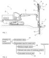
- FIG. 1 shows a rock drilling rig 1 intended for surface drilling.
- the rock drilling rig 1 comprises a movable carrier 2 and at least one drilling boom 3 connected to the carrier 2.
- a drilling unit 4 provided with a feed beam 5 and a rock drilling machine 6 supported on it.
- a drilling tool 7 is connectable to the drilling machine 6.
- the rock drilling machine 6 may comprise a shank adaptor at a front end of the rock drilling machine 6 for connecting the tool 7.
- the rock drilling machine 6 may comprise an impact device 8 and a rotating device 9.
- the rock drilling machine 6 may be moved on the feed beam 5 by means of a feed device 10.
- Drilling cuttings are flushed from a bottom of a drill hole 12 during drilling by conveying flushing flow trough the rock drilling machine 6 and the drilling tool 7 to a bottom of the drill hole 12.
- the drilling tool 7 may comprises tubular extension rods or tubes inside which is a flow channel for the flushing media. The drilling cuttings can move out of the drill hole when the flushing media flows through the drill bit 11.
- the carrier 2 may be provided with a compressor C for feeding pressurized air, and a liquid component source L for feeding one or more liquid components, for producing desired flow and composition for the air mist.
- a feed unit 13 for connecting the carrier 2 to one or more external sources of compressed air and liquid components.
- tubes, hoses and other flow channels for conveying the flushing media to the drilling unit 4 are not shown in Figure 1 .
- the air mist flushing system, and its devices and control elements can be controlled by means of one or more control units CU.
- the control unit CU may be provided with data on penetration rate and moisture content of drilling cuttings. Therefore, penetration rate may be detected by means of one or more sensors S1, and further, there may be one or more moisture sensors S2 in connection with a drilling cuttings removal system 14.
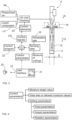
- Figure 2 discloses that for controlling feeding of the liquid component, penetration rate 15 and moisture target value 16 are input to the control unit.
- the system may compare sensed real values of moisture content 17 of the drilling cuttings and the moisture target value 16 when generating control signals.
- the system may calculate removal rate 18 of the removed drilling cuttings per time period during the drilling and may compare the calculated data to the moisture targe value 16.
- the removal rate can be calculated in response to data on diameter of a drill bit, data on density of the drilled rock material and the sensed penetration rate.
- the diameter D of the drill bit 11 is shown in Figure 3 .
- Figure 3 discloses features of the disclosed cuttings moisture control system, wherein the purpose is to keep moisture level of the removed drilling cuttings 19 relative constant despite of possible variations in the penetration rate 15 during drilling of one drill hole 12. It is advantageous to implement the disclosed automated flushing process and system in automated drilling processes.
- An operator 20 may input control parameters to the control unit CU by means of a user interface UI.
- the user interface UI may comprise one or more graphical elements 21 for assisting feeding of the parameters.
- the target value can be illustrated to the operator visually and in numerical values, such as percentage values.
- the graphical element 21 may show an allowable range inside which the desired values can be selected so that the operator 20 is assisted or forced to make reasonable selections in intuitive manner.
- the flushing may be controlled indirectly, since at first the operator selects the desired moisture percentage for the drilling cuttings and then the system calculates the amount of removed rock material during the drilling, and finally the system calculates how much water or other liquid component is needed to achieve the set moisture percentage.
- the operation is easy for the operator since only the target value needs to be input. The system takes care rest of the control and adjusts the flushing to possible external variations.
- the control unit CU is provided with one or more computer program products 22 or control algorithms which may be executed in a processor of the control unit CU.
- the control unit CU is provided with required input control parameters and sensing data, and is configured to generate control signals CS for one or more control elements 23 controlling at least the feeding of the liquid component LC, and possibly also controlling feeding of the pressurized air PA.
- the control element 23 may be a pump or valve, for example.
- FIG 4 discloses some control parameters of the drilling and flushing processes.
- the flushing parameters have been disclosed already above in this document.
- the drilling parameters may be feed parameters (speed, force), impact parameters (energy, frequency) and rotation parameters (speed, torque).
- the drilling parameters are also taken into account when controlling the flushing. Further, used drilling tool may have effect on the flushing process control.
- Figure 5 shows a moisture target level 24 [%], penetration rate 15 [m/min], sensed flow of liquid component 25 [l/min] and calculated moisture content of drilling cuttings 26 [%] in one combined presentation.
- the calculated moisture content 26 is calculated on the basis of data on the sensed flow of liquid component 25 and the sensed penetration rate 15.
- An arrow 27 shows that the penetration rate 15 decreases due to factors external to the drilling control. The drilled rock may be changed to harder, for example.
- the penetration rate decreases, the calculated moisture content 26 increases, whereby the flushing control system decreases flow of liquid component, as can be seen when examining the curve 25. Then new balance is found.
- the flushing system takes into account the changes in the penetration rate 15 and tries to keep the curve 26 close to the set target level 24.
- Figure 6 discloses that there may be several alternatives for the liquid component.
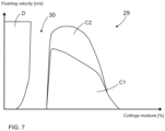
- FIG. 7 shows an example of a flushing map 29.
- Aim of the flushing map 29 is to illustrate flushing parameter values that are allowed. Too low amount of liquid component in the air mist may cause dusting wherefore parameters inside a dusting area D should be avoided. When too high amount of liquid component is used, then there is a risk of clogging. Therefore, operating parameters inside a forbidden clogging area C1 must be avoided. There is also a second clogging area C2, inside which clogging is possible, and that area should also be avoided, if possible. Operating parameters which lead to situations between the areas D and C1, and marked with an arrow 30, should thereby preferred in the flushing control to achieve the improved problem free air-mist flushing. There may be customized flushing maps for different drilling tool and rock types.
- the disclosed areas may be defined as data sets for the control unit. Further, the flushing maps and the used flushing parameters may be shown on display device of a rock drilling rig for the operator. This way valuable feed back can be provided for the operator.
Landscapes
- Engineering & Computer Science (AREA)
- Mining & Mineral Resources (AREA)
- Life Sciences & Earth Sciences (AREA)
- Geology (AREA)
- General Life Sciences & Earth Sciences (AREA)
- Geochemistry & Mineralogy (AREA)
- Physics & Mathematics (AREA)
- Environmental & Geological Engineering (AREA)
- Fluid Mechanics (AREA)
- Mechanical Engineering (AREA)
- Earth Drilling (AREA)
- Drilling And Exploitation, And Mining Machines And Methods (AREA)
Claims (12)
- Einrichtung zum Steuern der Luftnebelspülung einer Gesteinsbohreinheit (4), wobei der Luftnebel Druckluft (PA) und mindestens eine flüssige Komponente (LC) umfasst;und wobei die Einrichtung mindestens eine Steuereinheit (CU) zum Steuern der Zufuhr des Luftnebels umfasst;der Steuereinheit (CU) Daten zur Bohreindringrate (15) bereitgestellt werden;die Steuereinheit (CU) so konfiguriert ist, dass sie in Reaktion auf die eingegebenen Daten zur Eindringrate (15) und Parameter, die in die Steuereinheit (CU) eingegeben werden, Steuersignale (CS) zum Steuern der Zufuhr der mindestens einen flüssigen Komponente (LC) des Luftnebels erzeugt; und die Steuereinheit so konfiguriert ist, dass sie einen eingegebenen Sollwert (16) für den Feuchtigkeitsgehalt von Bohrklein (19), das aus dem gerade gebohrten Bohrloch (12) geräumt wird, empfängt;dadurch gekennzeichnet, dass die Steuereinheit weiter so konfiguriert ist, dass sieden tatsächlichen Wert des Feuchtigkeitsgehalts des Bohrkleins (19) bestimmt; unddie Zufuhr der flüssigen Komponente (LC) in Reaktion auf den Vergleich des eingegebenen Sollwerts (16) und des tatsächlichen Werts anpasst;wobei der Steuereinheit (CU) Sensordaten zur tatsächlichen Feuchtigkeit (17) des aus dem Bohrloch (12) geräumten Bohrkleins bereitgestellt werden, wobei die Steuereinheit (CU) mit einer Rückkopplungssteuerung bereitgestellt und so konfiguriert ist, dass sie die Zufuhr der flüssigen Komponente (LC) in Reaktion auf die eingegebenen Rückkopplungsdaten steuert.
- Einrichtung nach Anspruch 1, dadurch gekennzeichnet, dass die Steuereinheit so konfiguriert ist, dass sie:in Reaktion auf eingegebene Daten zum Durchmesser (D) eines Bohrmeißels (11), Daten zur Dichte des gebohrten Gesteinsmaterials und der Eindringrate (15) die Räumrate des geräumten Bohrkleins (19) pro Zeitspanne während des Bohrens berechnet;in Reaktion auf den eingegebenen Sollwert (16) für den Feuchtigkeitsgehalt und die berechneten Daten zur Räumrate des Bohrkleins die erforderliche Zufuhrrate der flüssigen Komponente berechnet.
- Einrichtung nach einem der Ansprüche 1 oder 2, dadurch gekennzeichnet, dass
die in die Steuereinheit (CU) eingegebenen Spülparameter Datensätze zu zulässigen Feuchtigkeitswerten des Feuchtigkeitsgehalts des Bohrkleins umfassen. - Einrichtung nach Anspruch 3, dadurch gekennzeichnet, dass
die Steuereinheit (CU) so konfiguriert ist, dass sie automatisch solche Steuerparameter aus dem Datensatz zu zulässigen Feuchtigkeitswerten auswählt, die die Zufuhr der flüssigen Komponente minimieren. - Einrichtung nach einem der Ansprüche 1-4, dadurch gekennzeichnet, dass
die Steuereinheit (CU) so konfiguriert ist, dass sie mindestens ein Flüssigkomponenten-Steuerelement (23) steuert. - Einrichtung nach einem der Ansprüche 1-5, dadurch gekennzeichnet, dass
die Steuereinheit (CU) so konfiguriert ist, dass sie in Reaktion auf die erfasste Eindringrate (15) zusätzlich die Zufuhr des Luftstroms steuert. - Gesteinsbohrgerät (1), umfassend:einen beweglichen Träger (2);mindestens einen Bohrarm (3), der in Bezug auf den Träger (2) beweglich montiert ist;mindestens eine Bohreinheit (4), die an dem mindestens einen Bohrarm (3) montiert ist und einen Zuführbalken (5) umfasst; eine Gesteinsbohrmaschine (6), die an dem Zuführbalken (5) montiert ist, und ein Bohrwerkzeug (7), das an der Gesteinsbohrmaschine (6) montiert werden kann;ein Luftnebel-Spülsystem zum Zuführen von Druckluft (PA) und mindestens einer flüssigen Komponente (LC) in ein Bohrloch (12);und eine Einrichtung zum Steuern des Luftnebel-Spülsystems;dadurch gekennzeichnet, dassdie Einrichtung gemäß einem der vorstehenden Ansprüche 1-6 ist.
- Verfahren zum Steuern der Spülung beim Gesteinsbohren, wobei das Verfahren umfasst:Verwenden einer Luftnebelspülung, wobei das Spülfluid Druckluft (PA) und mindestens eine flüssige Komponente (LC) umfasst;Empfangen eines eingegebenen Sollwerts (16) für den Feuchtigkeitsgehalt von Bohrklein (19), das während des Bohrens aus dem Bohrloch (12) ausgespült wird;Steuern der Zufuhr des Luftnebels zu einem Spülsystem während des Bohrens mittels mindestens einer Steuereinheit (CU);Erfassen der Eindringrate (15) des Bohrens; undSteuern der Zufuhr der mindestens einen flüssigen Komponente (LC) des Luftnebels in Reaktion auf die erfasste Eindringrate (15) und in die Steuereinheit (CU) eingegebene Parameter;gekennzeichnet durchBestimmen des tatsächlichen Werts des Feuchtigkeitsgehalts des Bohrkleins (19);Anpassen der Zufuhr der flüssigen Komponente (LC) in Reaktion auf den Vergleich des eingegebenen Sollwerts (16) und des tatsächlichen Werts;Empfangen von Sensordaten zur tatsächlichen Feuchtigkeit (17) des aus dem Bohrloch (12) geräumten Bohrkleins, wobei die Steuereinheit (CU) mit einer Rückkopplungssteuerung bereitgestellt ist; undSteuern der Zufuhr der flüssigen Komponente (LC) in Reaktion auf die eingegebenen Rückkopplungsdaten.
- Verfahren nach Anspruch 8, gekennzeichnet durch
Konstanthalten des Feuchtigkeitsgehalts des aus dem Bohrloch (12) augespülten Bohrkleins (19) bei jedem untersuchten Bohrloch (12) trotz variierender Eindringrate (15) während des Bohrens des Bohrlochs (12). - Verfahren nach einem der vorstehenden Ansprüche 8-9, gekennzeichnet durchBerechnen des Feststoffvolumens des geräumten und gespülten Bohrkleins (19) pro Zeitspanne in der Steuereinheit (CU) in Reaktion auf Daten zum Durchmesser (D) eines Bohrwerkzeugs (7, 11) und der erfassten Eindringrate (15);Bereitstellen eines Sollwerts (16) für die Steuereinheit (CU), der relative Mengen zwischen der flüssigen Komponente (LC) des Luftnebels und dem berechneten Feststoffvolumen des Bohrkleins (19) definiert; undSteuern der Zufuhr der flüssigen Komponente (LC) in Übereinstimmung mit dem Sollwert (16).
- Verfahren nach einem der vorstehenden Ansprüche 8-10, gekennzeichnet durchBereitstellen von vorbestimmten Datensätzen, die den zulässigen Feuchtigkeitsgehalt des Bohrkleins (19) definieren, für die Steuereinheit (CU); undBereitstellen von Hilfe für einen Bediener (20) bei der Auswahl von zulässigen Parametern für die beim Bohren verwendete Luftnebelspülung auf einer Benutzeroberfläche (UI).
- Computerprogrammprodukt (22) zum Steuern der Zufuhr einer Luftnebelspülung beim Gesteinsbohren, wobei das Computerprogrammprodukt (22) Anweisungen umfasst, um die Vorrichtung nach den Ansprüchen 1-7 dazu zu bringen, die Schritte des Verfahrens nach den Ansprüchen 8-11 auszuführen.
Priority Applications (9)
| Application Number | Priority Date | Filing Date | Title |
|---|---|---|---|
| EP21171309.4A EP4083371B1 (de) | 2021-04-29 | 2021-04-29 | Vorrichtung und verfahren zur steuerung der spülung beim gesteinsbohren |
| JP2023566564A JP7804696B2 (ja) | 2021-04-29 | 2022-04-21 | 削岩におけるフラッシングを制御するための装置および方法 |
| US18/288,292 US12158047B2 (en) | 2021-04-29 | 2022-04-21 | Apparatus and method for controlling flushing in rock drilling |
| AU2022267680A AU2022267680A1 (en) | 2021-04-29 | 2022-04-21 | Apparatus and method for controlling flushing in rock drilling |
| PCT/EP2022/060503 WO2022228981A1 (en) | 2021-04-29 | 2022-04-21 | Apparatus and method for controlling flushing in rock drilling |
| CN202280029451.0A CN117178104A (zh) | 2021-04-29 | 2022-04-21 | 用于控制岩石钻凿中的冲洗的设备和方法 |
| CA3215319A CA3215319A1 (en) | 2021-04-29 | 2022-04-21 | Apparatus and method for controlling flushing in rock drilling |
| ZA2023/09640A ZA202309640B (en) | 2021-04-29 | 2023-10-16 | Apparatus and method for controlling flushing in rock drilling |
| CL2023003167A CL2023003167A1 (es) | 2021-04-29 | 2023-10-24 | Aparato y método para controlar el lavado en la perforación de rocas. |
Applications Claiming Priority (1)
| Application Number | Priority Date | Filing Date | Title |
|---|---|---|---|
| EP21171309.4A EP4083371B1 (de) | 2021-04-29 | 2021-04-29 | Vorrichtung und verfahren zur steuerung der spülung beim gesteinsbohren |
Publications (3)
| Publication Number | Publication Date |
|---|---|
| EP4083371A1 EP4083371A1 (de) | 2022-11-02 |
| EP4083371C0 EP4083371C0 (de) | 2023-11-15 |
| EP4083371B1 true EP4083371B1 (de) | 2023-11-15 |
Family
ID=75746327
Family Applications (1)
| Application Number | Title | Priority Date | Filing Date |
|---|---|---|---|
| EP21171309.4A Active EP4083371B1 (de) | 2021-04-29 | 2021-04-29 | Vorrichtung und verfahren zur steuerung der spülung beim gesteinsbohren |
Country Status (9)
| Country | Link |
|---|---|
| US (1) | US12158047B2 (de) |
| EP (1) | EP4083371B1 (de) |
| JP (1) | JP7804696B2 (de) |
| CN (1) | CN117178104A (de) |
| AU (1) | AU2022267680A1 (de) |
| CA (1) | CA3215319A1 (de) |
| CL (1) | CL2023003167A1 (de) |
| WO (1) | WO2022228981A1 (de) |
| ZA (1) | ZA202309640B (de) |
Cited By (1)
| Publication number | Priority date | Publication date | Assignee | Title |
|---|---|---|---|---|
| CN117178104A (zh) * | 2021-04-29 | 2023-12-05 | 山特维克矿山工程机械有限公司 | 用于控制岩石钻凿中的冲洗的设备和方法 |
Families Citing this family (1)
| Publication number | Priority date | Publication date | Assignee | Title |
|---|---|---|---|---|
| AU2023453042A1 (en) * | 2023-07-06 | 2026-01-22 | Epiroc Rock Drills Aktiebolag | A control system for controlling a waterflow for an autonomous drilling machine |
Family Cites Families (23)
| Publication number | Priority date | Publication date | Assignee | Title |
|---|---|---|---|---|
| US3308894A (en) * | 1964-04-24 | 1967-03-14 | Shell Oil Co | Monitoring system for gaseous fluid drill boreholes |
| SE434865B (sv) * | 1979-08-22 | 1984-08-20 | Atlas Copco Ab | Sett och anordning for bindning av borrdamm |
| JPH0529275Y2 (de) * | 1986-04-30 | 1993-07-27 | ||
| JPH10306676A (ja) * | 1997-04-30 | 1998-11-17 | Furukawa Co Ltd | 自動さく孔機 |
| US5944122A (en) * | 1997-12-04 | 1999-08-31 | Driltech Inc. | Methods and apparatus for controlling an air compressor in a drill string flushing system |
| JPH11247576A (ja) * | 1998-02-27 | 1999-09-14 | Furukawa Co Ltd | 集塵装置の運転停止装置 |
| US6845657B2 (en) * | 2002-03-28 | 2005-01-25 | Harrison R. Cooper Systems, Inc. | Apparatus for sampling drill hole cuttings |
| JP2004060401A (ja) | 2002-07-31 | 2004-02-26 | Furukawa Co Ltd | 繰粉検出装置 |
| US20040139866A1 (en) * | 2003-01-21 | 2004-07-22 | Perry Lopez | Method and system for treating and shaping drill cuttings leaving the well bore for transportation and/or disposal of drill cuttings |
| SE526923C2 (sv) | 2003-12-29 | 2005-11-22 | Atlas Copco Rock Drills Ab | Metod, system och anordning för att styra effektförbrukningen under en bergborrningsprocess |
| US8813870B2 (en) * | 2008-05-13 | 2014-08-26 | Atlas Copco Rock Drills Ab | Arrangement and a method for monitoring an air flow in a drill rig |
| FI20085848L (fi) * | 2008-09-10 | 2010-03-11 | Sandvik Mining & Constr Oy | Menetelmä porasoijan käsittelemiseksi, kallionporauslaitteen pölynkeruujärjestelmä sekä vaihdinyksikkö |
| FI20085905A7 (fi) * | 2008-09-25 | 2010-03-26 | Sandvik Mining & Construction Oy | Laitteisto pölyn sitomiseksi käytettävän veden määrän säätämiseksi |
| SE535418C2 (sv) * | 2010-08-26 | 2012-07-31 | Atlas Copco Rock Drills Ab | Metod och system för styrning av en kompressor vid en bergborrningsanordning samt bergborrningsanordning |
| SE535421C2 (sv) * | 2010-08-26 | 2012-07-31 | Atlas Copco Rock Drills Ab | Förfarande och system för bestämning av en förändring av ett spolmediumflöde samt bergborrningsanordning |
| JP6117538B2 (ja) | 2012-12-07 | 2017-04-19 | 古河ロックドリル株式会社 | 穿孔用フラッシング媒体供給装置 |
| EP2955319A1 (de) | 2014-06-13 | 2015-12-16 | Sandvik Mining and Construction Oy | Anordnung und Verfahren zur Zuführung von Spülflüssigkeit |
| CA2900101C (en) * | 2014-08-13 | 2023-01-03 | Harnischfeger Technologies, Inc. | Automatic dust suppression system and method |
| US10428638B2 (en) * | 2016-12-06 | 2019-10-01 | Epiroc Drilling Solutions, Llc | System and method for controlling a drilling machine |
| CN107345476A (zh) * | 2017-08-25 | 2017-11-14 | 四川吉赛特科技有限公司 | 潜孔旋转振击空气钻井粉尘控制器 |
| EP3670831B1 (de) * | 2018-12-21 | 2023-02-15 | Sandvik Mining and Construction Oy | Gesteinsbohrmaschine, gesteinsbohrgestell und messverfahren |
| US11199062B1 (en) * | 2020-12-15 | 2021-12-14 | Caterpillar Global Mining Equipment Llc | Systems, methods, and apparatuses for identifying groundwater during rock drill cutting |
| EP4083371B1 (de) * | 2021-04-29 | 2023-11-15 | Sandvik Mining and Construction Oy | Vorrichtung und verfahren zur steuerung der spülung beim gesteinsbohren |
-
2021
- 2021-04-29 EP EP21171309.4A patent/EP4083371B1/de active Active
-
2022
- 2022-04-21 US US18/288,292 patent/US12158047B2/en active Active
- 2022-04-21 CA CA3215319A patent/CA3215319A1/en active Pending
- 2022-04-21 CN CN202280029451.0A patent/CN117178104A/zh active Pending
- 2022-04-21 AU AU2022267680A patent/AU2022267680A1/en active Pending
- 2022-04-21 WO PCT/EP2022/060503 patent/WO2022228981A1/en not_active Ceased
- 2022-04-21 JP JP2023566564A patent/JP7804696B2/ja active Active
-
2023
- 2023-10-16 ZA ZA2023/09640A patent/ZA202309640B/en unknown
- 2023-10-24 CL CL2023003167A patent/CL2023003167A1/es unknown
Cited By (1)
| Publication number | Priority date | Publication date | Assignee | Title |
|---|---|---|---|---|
| CN117178104A (zh) * | 2021-04-29 | 2023-12-05 | 山特维克矿山工程机械有限公司 | 用于控制岩石钻凿中的冲洗的设备和方法 |
Also Published As
| Publication number | Publication date |
|---|---|
| CN117178104A (zh) | 2023-12-05 |
| CA3215319A1 (en) | 2022-11-03 |
| CL2023003167A1 (es) | 2024-06-21 |
| US12158047B2 (en) | 2024-12-03 |
| US20240209701A1 (en) | 2024-06-27 |
| EP4083371C0 (de) | 2023-11-15 |
| AU2022267680A1 (en) | 2023-11-09 |
| WO2022228981A1 (en) | 2022-11-03 |
| JP2024515328A (ja) | 2024-04-08 |
| JP7804696B2 (ja) | 2026-01-22 |
| EP4083371A1 (de) | 2022-11-02 |
| ZA202309640B (en) | 2025-06-25 |
Similar Documents
| Publication | Publication Date | Title |
|---|---|---|
| CN101765694B (zh) | 用于控制岩石钻凿装置的方法和设备 | |
| US12158047B2 (en) | Apparatus and method for controlling flushing in rock drilling | |
| US7828083B2 (en) | Method of controlling operation of rock drilling rig, and rock drilling rig | |
| KR102409875B1 (ko) | 토양 가공을 위한 방법 및 시공 장치 | |
| US7654337B2 (en) | Arrangement for controlling rock drilling | |
| AU2015203009B2 (en) | Arrangement and method for feeding flushing fluid | |
| EP2446114B1 (de) | Verfahren und vorrichtung zur steuerung einer steinbohrung | |
| FI125984B (fi) | Menetelmä kallioporan syöttönopeuden ohjaamiseksi ja tietokonepohjainen ohjausjärjestelmä | |
| JP2024515328A5 (de) | ||
| US20260092520A1 (en) | Adaptive collaring using rock fracture indication | |
| HK40004360A (en) | Method and construction apparatus for working the soil | |
| HK40004360B (zh) | 用於进行土壤作业的方法和建筑设备 |
Legal Events
| Date | Code | Title | Description |
|---|---|---|---|
| PUAI | Public reference made under article 153(3) epc to a published international application that has entered the european phase |
Free format text: ORIGINAL CODE: 0009012 |
|
| STAA | Information on the status of an ep patent application or granted ep patent |
Free format text: STATUS: THE APPLICATION HAS BEEN PUBLISHED |
|
| AK | Designated contracting states |
Kind code of ref document: A1 Designated state(s): AL AT BE BG CH CY CZ DE DK EE ES FI FR GB GR HR HU IE IS IT LI LT LU LV MC MK MT NL NO PL PT RO RS SE SI SK SM TR |
|
| STAA | Information on the status of an ep patent application or granted ep patent |
Free format text: STATUS: REQUEST FOR EXAMINATION WAS MADE |
|
| 17P | Request for examination filed |
Effective date: 20230502 |
|
| RBV | Designated contracting states (corrected) |
Designated state(s): AL AT BE BG CH CY CZ DE DK EE ES FI FR GB GR HR HU IE IS IT LI LT LU LV MC MK MT NL NO PL PT RO RS SE SI SK SM TR |
|
| P01 | Opt-out of the competence of the unified patent court (upc) registered |
Effective date: 20230603 |
|
| GRAP | Despatch of communication of intention to grant a patent |
Free format text: ORIGINAL CODE: EPIDOSNIGR1 |
|
| STAA | Information on the status of an ep patent application or granted ep patent |
Free format text: STATUS: GRANT OF PATENT IS INTENDED |
|
| INTG | Intention to grant announced |
Effective date: 20230726 |
|
| GRAS | Grant fee paid |
Free format text: ORIGINAL CODE: EPIDOSNIGR3 |
|
| GRAA | (expected) grant |
Free format text: ORIGINAL CODE: 0009210 |
|
| STAA | Information on the status of an ep patent application or granted ep patent |
Free format text: STATUS: THE PATENT HAS BEEN GRANTED |
|
| AK | Designated contracting states |
Kind code of ref document: B1 Designated state(s): AL AT BE BG CH CY CZ DE DK EE ES FI FR GB GR HR HU IE IS IT LI LT LU LV MC MK MT NL NO PL PT RO RS SE SI SK SM TR |
|
| REG | Reference to a national code |
Ref country code: CH Ref legal event code: EP Ref country code: GB Ref legal event code: FG4D |
|
| REG | Reference to a national code |
Ref country code: DE Ref legal event code: R096 Ref document number: 602021006754 Country of ref document: DE |
|
| REG | Reference to a national code |
Ref country code: IE Ref legal event code: FG4D |
|
| U01 | Request for unitary effect filed |
Effective date: 20231115 |
|
| U07 | Unitary effect registered |
Designated state(s): AT BE BG DE DK EE FI FR IT LT LU LV MT NL PT SE SI Effective date: 20231120 |
|
| P04 | Withdrawal of opt-out of the competence of the unified patent court (upc) registered |
Effective date: 20231115 |
|
| REG | Reference to a national code |
Ref country code: NO Ref legal event code: T2 Effective date: 20231115 |
|
| PG25 | Lapsed in a contracting state [announced via postgrant information from national office to epo] |
Ref country code: GR Free format text: LAPSE BECAUSE OF FAILURE TO SUBMIT A TRANSLATION OF THE DESCRIPTION OR TO PAY THE FEE WITHIN THE PRESCRIBED TIME-LIMIT Effective date: 20240216 |
|
| PG25 | Lapsed in a contracting state [announced via postgrant information from national office to epo] |
Ref country code: IS Free format text: LAPSE BECAUSE OF FAILURE TO SUBMIT A TRANSLATION OF THE DESCRIPTION OR TO PAY THE FEE WITHIN THE PRESCRIBED TIME-LIMIT Effective date: 20240315 |
|
| U20 | Renewal fee for the european patent with unitary effect paid |
Year of fee payment: 4 Effective date: 20240306 |
|
| PG25 | Lapsed in a contracting state [announced via postgrant information from national office to epo] |
Ref country code: ES Free format text: LAPSE BECAUSE OF FAILURE TO SUBMIT A TRANSLATION OF THE DESCRIPTION OR TO PAY THE FEE WITHIN THE PRESCRIBED TIME-LIMIT Effective date: 20231115 |
|
| PG25 | Lapsed in a contracting state [announced via postgrant information from national office to epo] |
Ref country code: IS Free format text: LAPSE BECAUSE OF FAILURE TO SUBMIT A TRANSLATION OF THE DESCRIPTION OR TO PAY THE FEE WITHIN THE PRESCRIBED TIME-LIMIT Effective date: 20240315 Ref country code: GR Free format text: LAPSE BECAUSE OF FAILURE TO SUBMIT A TRANSLATION OF THE DESCRIPTION OR TO PAY THE FEE WITHIN THE PRESCRIBED TIME-LIMIT Effective date: 20240216 Ref country code: ES Free format text: LAPSE BECAUSE OF FAILURE TO SUBMIT A TRANSLATION OF THE DESCRIPTION OR TO PAY THE FEE WITHIN THE PRESCRIBED TIME-LIMIT Effective date: 20231115 |
|
| PG25 | Lapsed in a contracting state [announced via postgrant information from national office to epo] |
Ref country code: RS Free format text: LAPSE BECAUSE OF FAILURE TO SUBMIT A TRANSLATION OF THE DESCRIPTION OR TO PAY THE FEE WITHIN THE PRESCRIBED TIME-LIMIT Effective date: 20231115 Ref country code: PL Free format text: LAPSE BECAUSE OF FAILURE TO SUBMIT A TRANSLATION OF THE DESCRIPTION OR TO PAY THE FEE WITHIN THE PRESCRIBED TIME-LIMIT Effective date: 20231115 Ref country code: HR Free format text: LAPSE BECAUSE OF FAILURE TO SUBMIT A TRANSLATION OF THE DESCRIPTION OR TO PAY THE FEE WITHIN THE PRESCRIBED TIME-LIMIT Effective date: 20231115 |
|
| PG25 | Lapsed in a contracting state [announced via postgrant information from national office to epo] |
Ref country code: CZ Free format text: LAPSE BECAUSE OF FAILURE TO SUBMIT A TRANSLATION OF THE DESCRIPTION OR TO PAY THE FEE WITHIN THE PRESCRIBED TIME-LIMIT Effective date: 20231115 |
|
| PG25 | Lapsed in a contracting state [announced via postgrant information from national office to epo] |
Ref country code: SK Free format text: LAPSE BECAUSE OF FAILURE TO SUBMIT A TRANSLATION OF THE DESCRIPTION OR TO PAY THE FEE WITHIN THE PRESCRIBED TIME-LIMIT Effective date: 20231115 |
|
| PG25 | Lapsed in a contracting state [announced via postgrant information from national office to epo] |
Ref country code: SM Free format text: LAPSE BECAUSE OF FAILURE TO SUBMIT A TRANSLATION OF THE DESCRIPTION OR TO PAY THE FEE WITHIN THE PRESCRIBED TIME-LIMIT Effective date: 20231115 Ref country code: SK Free format text: LAPSE BECAUSE OF FAILURE TO SUBMIT A TRANSLATION OF THE DESCRIPTION OR TO PAY THE FEE WITHIN THE PRESCRIBED TIME-LIMIT Effective date: 20231115 Ref country code: RO Free format text: LAPSE BECAUSE OF FAILURE TO SUBMIT A TRANSLATION OF THE DESCRIPTION OR TO PAY THE FEE WITHIN THE PRESCRIBED TIME-LIMIT Effective date: 20231115 Ref country code: CZ Free format text: LAPSE BECAUSE OF FAILURE TO SUBMIT A TRANSLATION OF THE DESCRIPTION OR TO PAY THE FEE WITHIN THE PRESCRIBED TIME-LIMIT Effective date: 20231115 |
|
| REG | Reference to a national code |
Ref country code: DE Ref legal event code: R097 Ref document number: 602021006754 Country of ref document: DE |
|
| PLBE | No opposition filed within time limit |
Free format text: ORIGINAL CODE: 0009261 |
|
| STAA | Information on the status of an ep patent application or granted ep patent |
Free format text: STATUS: NO OPPOSITION FILED WITHIN TIME LIMIT |
|
| 26N | No opposition filed |
Effective date: 20240819 |
|
| PG25 | Lapsed in a contracting state [announced via postgrant information from national office to epo] |
Ref country code: MC Free format text: LAPSE BECAUSE OF FAILURE TO SUBMIT A TRANSLATION OF THE DESCRIPTION OR TO PAY THE FEE WITHIN THE PRESCRIBED TIME-LIMIT Effective date: 20231115 |
|
| PG25 | Lapsed in a contracting state [announced via postgrant information from national office to epo] |
Ref country code: MC Free format text: LAPSE BECAUSE OF FAILURE TO SUBMIT A TRANSLATION OF THE DESCRIPTION OR TO PAY THE FEE WITHIN THE PRESCRIBED TIME-LIMIT Effective date: 20231115 |
|
| REG | Reference to a national code |
Ref country code: CH Ref legal event code: PL |
|
| P05 | Withdrawal of opt-out of the competence of the unified patent court (upc) changed |
Free format text: CASE NUMBER: APP_587457/2023 Effective date: 20231120 |
|
| PG25 | Lapsed in a contracting state [announced via postgrant information from national office to epo] |
Ref country code: CH Free format text: LAPSE BECAUSE OF NON-PAYMENT OF DUE FEES Effective date: 20240430 |
|
| PG25 | Lapsed in a contracting state [announced via postgrant information from national office to epo] |
Ref country code: IE Free format text: LAPSE BECAUSE OF NON-PAYMENT OF DUE FEES Effective date: 20240429 |
|
| U20 | Renewal fee for the european patent with unitary effect paid |
Year of fee payment: 5 Effective date: 20250430 |
|
| PGFP | Annual fee paid to national office [announced via postgrant information from national office to epo] |
Ref country code: NO Payment date: 20250409 Year of fee payment: 5 |
|
| PGFP | Annual fee paid to national office [announced via postgrant information from national office to epo] |
Ref country code: TR Payment date: 20250424 Year of fee payment: 5 |
|
| PG25 | Lapsed in a contracting state [announced via postgrant information from national office to epo] |
Ref country code: CY Free format text: LAPSE BECAUSE OF FAILURE TO SUBMIT A TRANSLATION OF THE DESCRIPTION OR TO PAY THE FEE WITHIN THE PRESCRIBED TIME-LIMIT; INVALID AB INITIO Effective date: 20210429 |
|
| PG25 | Lapsed in a contracting state [announced via postgrant information from national office to epo] |
Ref country code: HU Free format text: LAPSE BECAUSE OF FAILURE TO SUBMIT A TRANSLATION OF THE DESCRIPTION OR TO PAY THE FEE WITHIN THE PRESCRIBED TIME-LIMIT; INVALID AB INITIO Effective date: 20210429 |
|
| GBPC | Gb: european patent ceased through non-payment of renewal fee |
Effective date: 20250429 |
|
| PG25 | Lapsed in a contracting state [announced via postgrant information from national office to epo] |
Ref country code: GB Free format text: LAPSE BECAUSE OF NON-PAYMENT OF DUE FEES Effective date: 20250429 |