EP4082645A1 - Filter disk segments - Google Patents
Filter disk segments Download PDFInfo
- Publication number
- EP4082645A1 EP4082645A1 EP22168436.8A EP22168436A EP4082645A1 EP 4082645 A1 EP4082645 A1 EP 4082645A1 EP 22168436 A EP22168436 A EP 22168436A EP 4082645 A1 EP4082645 A1 EP 4082645A1
- Authority
- EP
- European Patent Office
- Prior art keywords
- porous
- component
- fluid flow
- filter
- flow channels
- Prior art date
- Legal status (The legal status is an assumption and is not a legal conclusion. Google has not performed a legal analysis and makes no representation as to the accuracy of the status listed.)
- Granted
Links
Images









Classifications
-
- B—PERFORMING OPERATIONS; TRANSPORTING
- B01—PHYSICAL OR CHEMICAL PROCESSES OR APPARATUS IN GENERAL
- B01D—SEPARATION
- B01D24/00—Filters comprising loose filtering material, i.e. filtering material without any binder between the individual particles or fibres thereof
- B01D24/007—Filters comprising loose filtering material, i.e. filtering material without any binder between the individual particles or fibres thereof with multiple filtering elements in series connection
- B01D24/008—Filters comprising loose filtering material, i.e. filtering material without any binder between the individual particles or fibres thereof with multiple filtering elements in series connection arranged concentrically or coaxially
-
- B—PERFORMING OPERATIONS; TRANSPORTING
- B01—PHYSICAL OR CHEMICAL PROCESSES OR APPARATUS IN GENERAL
- B01D—SEPARATION
- B01D25/00—Filters formed by clamping together several filtering elements or parts of such elements
- B01D25/22—Cell-type filters
- B01D25/26—Cell-type stack filters
-
- B—PERFORMING OPERATIONS; TRANSPORTING
- B01—PHYSICAL OR CHEMICAL PROCESSES OR APPARATUS IN GENERAL
- B01D—SEPARATION
- B01D29/00—Filters with filtering elements stationary during filtration, e.g. pressure or suction filters, not covered by groups B01D24/00 - B01D27/00; Filtering elements therefor
- B01D29/39—Filters with filtering elements stationary during filtration, e.g. pressure or suction filters, not covered by groups B01D24/00 - B01D27/00; Filtering elements therefor with hollow discs side by side on, or around, one or more tubes, e.g. of the leaf type
- B01D29/41—Filters with filtering elements stationary during filtration, e.g. pressure or suction filters, not covered by groups B01D24/00 - B01D27/00; Filtering elements therefor with hollow discs side by side on, or around, one or more tubes, e.g. of the leaf type mounted transversely on the tube
-
- B—PERFORMING OPERATIONS; TRANSPORTING
- B01—PHYSICAL OR CHEMICAL PROCESSES OR APPARATUS IN GENERAL
- B01D—SEPARATION
- B01D29/00—Filters with filtering elements stationary during filtration, e.g. pressure or suction filters, not covered by groups B01D24/00 - B01D27/00; Filtering elements therefor
- B01D29/39—Filters with filtering elements stationary during filtration, e.g. pressure or suction filters, not covered by groups B01D24/00 - B01D27/00; Filtering elements therefor with hollow discs side by side on, or around, one or more tubes, e.g. of the leaf type
-
- B—PERFORMING OPERATIONS; TRANSPORTING
- B01—PHYSICAL OR CHEMICAL PROCESSES OR APPARATUS IN GENERAL
- B01D—SEPARATION
- B01D24/00—Filters comprising loose filtering material, i.e. filtering material without any binder between the individual particles or fibres thereof
- B01D24/02—Filters comprising loose filtering material, i.e. filtering material without any binder between the individual particles or fibres thereof with the filter bed stationary during the filtration
- B01D24/04—Filters comprising loose filtering material, i.e. filtering material without any binder between the individual particles or fibres thereof with the filter bed stationary during the filtration the filtering material being clamped between pervious fixed walls
-
- B—PERFORMING OPERATIONS; TRANSPORTING
- B01—PHYSICAL OR CHEMICAL PROCESSES OR APPARATUS IN GENERAL
- B01D—SEPARATION
- B01D29/00—Filters with filtering elements stationary during filtration, e.g. pressure or suction filters, not covered by groups B01D24/00 - B01D27/00; Filtering elements therefor
- B01D29/88—Filters with filtering elements stationary during filtration, e.g. pressure or suction filters, not covered by groups B01D24/00 - B01D27/00; Filtering elements therefor having feed or discharge devices
Definitions
- filter disk segments include a plurality of separately produced components, for example, a spacer, filter media, and a slotted support.
- a spacer for example, a spacer, filter media, and a slotted support.
- filter disk segments there is a need for improved filter disk segments.
- the present invention provides for ameliorating at least some of the disadvantages of the prior art.
- An aspect of the invention provides a filter disk segment comprising (a) a filter element disk comprising a central hub having a central hub opening; (i) a first porous component including a first end by the central hub opening, and a second end distal to the first end, the first porous component having an upper surface including at least two raised fluid flow channels having porous walls, each of the at least two raised fluid flow channels extending toward the first end and the second end, and a lower surface facing a drainage component; (ii) a second porous component including a first end by the central hub opening, and a second end distal to the first end, the second porous component having an upper surface facing the drainage component and a lower surface including at least two raised fluid flow channels having porous walls, each of the at least two raised fluid flow channels extending toward the first end and the second end; (iii) the drainage component allowing fluid flow therethrough arranged between, and in fluid communication with, the first porous component and the second porous component, the drainage component including the central hub opening; wherein the central
- a filter disk segment comprising (a) a filter element disk comprising a central hub having a central hub opening; (i) a first porous component including a first end by the central hub opening, and a second end distal to the first end, the first porous component having an upper surface including at least two raised porous ribs, each of the at least two raised porous ribs extending toward the first end and the second end, and a lower surface facing a drainage component, the lower surface including at least two fluid flow channels, each of the at least two fluid flow channels extending toward the first end and the second end; (ii) a second porous component including a first end by the central hub opening, and a second end distal to the first end, the second porous component having an upper surface facing the drainage component, the upper surface including at least two fluid flow channels, each of the at least two fluid flow channels extending toward the first end and the second end, and a lower surface including at least two raised porous ribs, each of the at least two raised
- Another aspect of the invention comprises a filter device comprising at least two filter disk segments according to an aspect of the invention, the filter device comprising an inlet and an outlet and defining a fluid flow path between the inlet and the outlet, with the at least two filter disk segments arranged in the housing across the fluid flow path.
- a method of filtering fluid according to an aspect of the invention comprising passing the fluid through at least one filter disk segment, preferably, at least two filter disk segments, more preferably passing the fluid through a filter device comprising at least two filter disk segments according to an aspect of the invention.
- a filter disk segment comprises (a) a filter element disk comprising a central hub having a central hub opening; (i) a first porous component including a first end by the central hub opening, and a second end distal to the first end, the first porous component having an upper surface including at least two raised fluid flow channels having porous walls, each of the at least two raised fluid flow channels extending toward the first end and the second end, and a lower surface facing a drainage component; (ii) a second porous component including a first end by the central hub opening, and a second end distal to the first end, the second porous component having an upper surface facing the drainage component and a lower surface including at least two raised fluid flow channels having porous walls, each of the at least two raised fluid flow channels extending toward the first end and the second end; (iii) the drainage component allowing fluid flow therethrough arranged between, and in fluid communication with, the first porous component and the second porous component, the drainage component including the central hub opening; wherein
- a filter disk segment comprising (a) a filter element disk comprising a central hub having a central hub opening; (i) a first porous component including a first end by the central hub opening, and a second end distal to the first end, the first porous component having an upper surface including at least two raised porous ribs, each of the at least two raised porous ribs extending toward the first end and the second end, and a lower surface facing a drainage component, the lower surface including at least two fluid flow channels, each of the at least two fluid flow channels extending toward the first end and the second end; (ii) a second porous component including a first end by the central hub opening, and a second end distal to the first end, the second porous component having an upper surface facing the drainage component, the upper surface including at least two fluid flow channels, each of the at least two fluid flow channels extending toward the first end and the second end, and a lower surface including at least two raised porous ribs, each of the at least two raised
- each of the at least two raised fluid flow channels in the first porous component and in the second porous component extend continuously from the first end to the second end.
- the at least two raised fluid flow channels in the first porous component are offset from the at least two raised fluid flow channels in the second porous component.
- each of the at least two raised porous ribs and each of the at least two fluid flow channels in the first porous component and in the second porous component extend continuously from the first end to the second end.
- the at least two raised porous ribs in the first porous component are offset from the at least two fluid flow channels in the first porous component, and the at least two raised porous ribs in the second porous component are offset from the at least two fluid flow channels in the second porous component.
- each of the at least two raised fluid flow channels and/or each of the at least two raised porous ribs in the first porous component and in the second porous component are curved in shape between the first end and the second end.
- Channel curvature can remain at a constant pitch or can vary continuously along the length of a channel.
- each of the at least two raised fluid flow channels in the first porous component and in the second porous component have cross-sectional areas that change between the first end and the second end, preferably, wherein each of the at least two raised fluid flow channels in the first porous component and in the second porous component have cross-sectional areas that decrease from the second end to the first end.
- the ratio between the channel width at the first end to the channel width at the second end is greater than 1, and decreases going outward from the first end to the second end, advantageously keeping the fluid flow rate through the channel at a desirably high rate.
- the ratio can be in the range from greater to 1 to about 8.
- each of the at least two raised fluid flow channels in the first porous component and in the second porous component have an open area in the respective lower surface or upper surface facing the drainage component.
- a variety of fluid flow channel heights or depths are suitable for use in aspects of the invention.
- the height/depth is at least about .04;" in some aspects, in the range of from about .04" to about 0.125".
- a variety of fluid flow channel widths are suitable for use in aspects of the invention.
- the channel width to channel height/depth ratio at the first end is typically in the range of from about 0.12 to about 8, in some aspects, about 1.5
- Porous components can have any number of fluid flow channels and/or raised porous ribs. Typically, the number of fluid flow channels is in the range of from 4 to about 120.
- a space between adjacent filter disk segments typically, a space between the exterior flat portions of the porous components of adjacent filter disk elements of the adjacent filter disk segments of at least about twice the height of the height of the raised channels and/or raised ribs on a single filter element disk.
- Another aspect of the invention comprises a porous filter comprising at least two filter disk segments according to an aspect of the invention.
- Another aspect of the invention comprises a filter device comprising a porous filter comprising at least two filter disk segments according to an aspect of the invention, the filter device comprising an inlet and an outlet and defining a fluid flow path between the inlet and the outlet, with the porous filter arranged in the housing across the fluid flow path.
- a method of filtering fluid according to an aspect of the invention comprising passing the fluid through at least one filter disk segment, preferably, at least two filter disk segments, more preferably passing the fluid through a filter device comprising at least two filter disk segments according to an aspect of the invention.
- the fluid is passed from the outside of the filter disk segment(s) through the inside (e.g., through the central hub).
- a fluid is passed, into the filter disk segments through the top and bottom porous components (filtering media), forming a filtrate that is passed through the drainage component, and the filtrate passes along the fluid flow channels to the central hub and through the outlet of the filter device.
- filter disk segments can be produced with fewer components while eliminating a manufacturing step. Additionally, increased effective filter area can be provided while preserving desirable residence time, without resulting in excess residence time that could degrade the filter media. Eliminating a component such as a separate slotted support plate reduces the disk segment height (thickness) allowing more disk segments to fit in the previously used housings, thus providing increased filtering efficiency.
- the use of raised fluid flow channels and/or raised ribs can provide additional effective filter areas compared to flat disks of media. Alternatively, or additionally, the raised fluid flow channels and/or raised ribs can provide spacing between adjacent filter disk segments, which can assist in efficient fluid flow.
- FIGS 1A and 1B show a perspective view of two assembled filter disk segments 500 according to an aspect of the invention, each filter disk segment comprising a filter element disk 400 comprising a central hub 401 (in some embodiments the central hub is welded to the porous component) having a central hub opening 402; (i) a first porous component 100 including a first end 101 by the central hub opening 402, and a second end 102 distal to the first end, the first porous component having an upper surface 110 including at least two raised fluid flow channels 112 having porous walls 112A and inner diameters 112B (see Figure 2A ), each of the at least two raised fluid flow channels extending toward the first end and the second end (illustrated as curved, and continuous from one end to the other), and a lower surface 120 facing (as shown in Figure 5B ) the upper surface 310 of a drainage component 300; (ii) a second porous component 200 including a first end 201 by the central hub opening 402, and a second end 202 distal to the first
- the porous components are identical, and one porous component is inverted and the first and second porous components are placed together resulting in the fluid flow channels on the respective porous components curving in opposite directions.
- adjacent filter disk segments are arranged such that the filter element disc of a first filter disk segment has fluid flow channels curved in one direction and the filter element disc of the second filter disk segment (that faces the filter element disc of the first filter disk segment) has fluid flow channels curved in the other direction ( see , Figure 3A ; see also , Figure 5E showing the fluid flow channels in the upper and lower porous components of a filter disk segment curving in opposite directions).
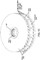
- FIG 1C is an exploded view of two commercially available filter disk segment.
- each commercially available filter disk segment has two layers of porous media, two layers of mesh, a slotted support, and a separate intersegment spacer is present between adjacent segments.
- Figure 2A shows fluid flow through the porous wall 112A of the raised flow channel 112 having an inner diameter 112B according to the aspect of the filter disk segment shown in Figure 1A (212A, 212, 212B arranged the same way), illustrating fluid flow accessing more filter surface area before passing through drainage component 300, in contrast with, as shown in Figure 2B , fluid flow through the porous media of the commercially available filter disk segment, wherein the fluid flow accesses less filter surface area.
- Figure 3A is a diagrammatic view showing fluid flow through the gap between adjacent filter disk segments 500 (between the lower porous component of one filter disc segment and the upper porous component of the next filter disc segment, the porous component having flow channels curved in opposite directions) before passing through the porous components (filter media) 100, 200 according to an aspect of the invention, also showing less flow area due to raised fluid flow channels 112, 212 (the raised flow channels take up space and reduce flow volume in the gap between filter disk segments), resulting in lower residence time in the gap, thus minimizing polymer burning;
- Figure 3B is a diagrammatic view showing fluid flow through the gap between adjacent filter disk segments due to the spacer between adjacent filter disk segments before passing through the filter media in a commercially available filter disk segment, wherein an increased residence time can result in increased polymer burning.
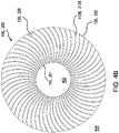
- Figure 4A is a top view of a porous component 100, 200 of a filter element disk 400 according to an aspect of the invention.
- each of the at least two raised fluid flow channels in the first porous component and in the second porous component have cross-sectional areas that change between the first end and the second end, preferably, wherein each of the at least two raised fluid flow channels in the first porous component and in the second porous component have cross-sectional areas that increase from the second end to the first end.
- Figure 4B is a bottom view of the aspect of the porous component 101, 201 of the filter element disc 400 shown in Figure 4A , also showing the respective surfaces 120, 220, and the cross-sectional areas of the fluid flow channels 112 (112B), 212 (212B) increasing from the second (outer) end 102, 202 of the element disk toward the first (inner) end 101, 201 by the central hub opening 402;
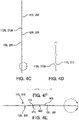
- Figure 4C is a side view of the aspect of the porous component of a filter element disk shown in Figure 4A ;
- Figure 4D is an enlarged view of region "A" shown in Figure 4C;
- Figure 4E is a cross-sectional view along line B-B of the porous component of the filter element disk shown in Figure 4A , also showing central hub 401, central hub opening 402, and the ends of flow channels 112, 212 at the first (inner) ends 101, 201.
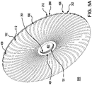
- FIGS 5A and 5B are isometric top views of a filter disk segment 500 including filter element disk 400 according to an aspect of the invention including porous components 100, 200 and central hub 401, wherein the central hubs are welded to the porous components, the drainage component 300 (as shown in Figure 5B ) having a upper surface 310 and a lower surface 320, welded edge of filter disk segment not shown;
- Figure 5C is a side view of the filter disk segment shown in Figure 5A ;
- Figure 5D is an enlarged view of region "A" shown in Figure 5C , showing the respective fluid flow channels 112 and 212 are offset from each other.
- the first and second porous components are identical, so when placed on opposite sides of the drainage component in forming a filter disk segment, the fluid flow channels 112, 212 in the respective porous components 100, 200, are curved in opposite directions, as shown in Figure 5E (wherein fluid flow channels 212 are shown through porous component 100 in broken lines).
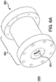
- FIG 6A is a perspective view of an aspect of a filter device 1000 including a housing 900 having an inlet 901 and an outlet 902, and, as shown in the cross-sectional view of the device in Figure 6B , a filter unit 700 comprising porous filter 600 comprising plurality of disk segments 500 (or 500' as described below) arranged on a hollow perforated central core 703 (perforations 704) between end caps 701 (open end cap), 702 (closed end cap) wherein the filter unit is arranged in the housing according to an aspect of the invention.
- a filter unit 700 comprising porous filter 600 comprising plurality of disk segments 500 (or 500' as described below) arranged on a hollow perforated central core 703 (perforations 704) between end caps 701 (open end cap), 702 (closed end cap) wherein the filter unit is arranged in the housing according to an aspect of the invention.
- Figure 7 shows a plurality of filter disk segments 500 (or 500' as described below) forming porous filter 600 (arranged for outside to inside fluid flow and through the central hub of the disk segments), also showing space between adjacent filter disk segments, wherein each filter disk segment is sealed (e.g., welded) at the edges.
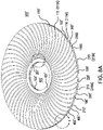
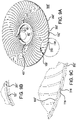
- Figure 8A is an isometric top view of first and second porous component 100', 200' of filter element disk 400' providing a filter disk segment 500' according to another aspect of the invention (drainage component not shown between porous components 100' and 200'), having first (inner) ends 101', 201' and second (outer) ends 102', 202' and including a plurality of raised porous ribs 115, 215 (with respective porous walls 115A, 215A) on one surface 110', 210', and a plurality of fluid flow channels 116, 216 with porous walls 116A, 216A and having inner diameters 116B, 216B in the other surface 120', 220,' wherein the fluid flow channels 116, 216 are offset from each other at the second ends 102', 202';
- Figure 8B is an enlarged view of region "A" (showing a single porous component representing the first and second porous components) including the first ends 101', 201' shown in Figure 8A
- the first and second porous components are identical, so when placed on opposite sides of the drainage component in the respective porous components curved in opposite directions) the flow channels are slightly or completely offset from each other the second ends, though they can be aligned at the second ends if desired.
- the raised porous ribs can assist in providing spacing between adjacent filter element disks.
- Figure 9A is a perspective view of an assembled filter disk segment 500' including porous components as shown in Figure 8A , wherein the fluid flow channels 116, 216 are slightly offset from each other with some overlap at the second ends 102', 202';
- Figure 9B is an enlarged view of region "A" shown in Figure 9A;
- Figure 9C is an enlarged view of region "B" shown in Figure 9A .
- the porous components can have any suitable pore structure, e.g., a pore size (for example, as evidenced by bubble point, or by K L as described in, for example, U.S. Patent 4,340,479 , or evidenced by capillary condensation flow porometry), a mean flow pore (MFP) size (e.g., when characterized using a porometer, for example, a Porvair Porometer (Porvair plc, Norfolk, UK), or a porometer available under the trademark POROLUX (Porometer.com; Belgium)), a pore rating, a pore diameter (e.g., when characterized using the modified OSU F2 test as described in, for example, U.S. Patent 4,925,572 ), or removal rating.
- the pore structure used depends on the size of the particles to be utilized, the composition of the fluid to be treated, and the desired effluent level of the treated fluid.
- the porous components 100, 200, 100', 200' each have a pore size in the range from about 0.5 microns to about 100 microns.
- the drainage component 300 that can also provide support, is typically configured as a mesh or screen, having openings larger than the pore structure of the porous components.
- the drainage component pressure drop of the drainage component is about 10% or less than the porous component pressure drop.
- a filter disk segment can have any desired critical wetting surface tension (CWST, as defined in, for example, U.S. Patent 4,925,572 ).
- the CWST can be selected as is known in the art, e.g., as additionally disclosed in, for example, U.S. Patents 5,152,905 , 5,443,743 , 5,472,621 , and 6,074,869 .
- the filter disk segment preferably at least two filter disk segments, is/are typically disposed in a housing comprising at least one inlet and at least one outlet and defining at least one fluid flow path between the inlet and the outlet, wherein the filter disk segments) is/are across the fluid flow path, to provide a filter device.
- the filter device is sterilizable. Any housing of suitable shape and providing at least one inlet and at least one outlet may be employed.
- a filter unit comprises a porous filter comprising at least two filter disk segments.
- the filter unit comprises a hollow aperture core.
- the filter unit further comprises end caps, and the filter unit is arranged in the filter device filter housing across the fluid flow path.
- Porous components according to aspects of the invention are preferably monolithic, preferably manufactured via additive manufacturing (sometimes referred to as “additive layer manufacturing” or “3D printing”). They are typically formed by repeated depositions of a metal powder bound together with an activatable binder (e.g., binder jetting, sometimes referred to as “drop on powder”), typically followed by agglomerating the powder, e.g., by sintering.
- additive manufacturing sometimes referred to as “additive layer manufacturing” or “3D printing”
- an activatable binder e.g., binder jetting, sometimes referred to as “drop on powder
- Any suitable additive manufacturing equipment can be used, and a variety of production 3D printers are suitable and commercially available.
- This example demonstrates the simulated performance of a filter disk segment according to an aspect of the invention in comparison to a commercially available filter disk segment having a separate slotted disk between the filter media, using a fixed upstream pressure.
- a 12 inch nominal filter disk segment as generally shown in Figures 5A and 5B having 54 fluid flow channels, about .08 media thickness and about .10 inch channel width at the hub in each filter element disc, and a commercially available filter disk segment (LEAF DISK, Pall Corporation, East Hills, NY) as generally shown in Figure 1C , are tested, using clean polyethylene terephthalate (PET) fluid and 522 psi upstream pressures.
- PET polyethylene terephthalate
- a filter disc segment according to an aspect of the invention can provide a higher flow rate, reduced residence time, and allow an increased number of discs fit into the same housing in comparison to a commercially available disc segment with similar pressures and pressure drops.
- This example demonstrates the simulated performance of a filter disk segment according to an aspect of the invention in comparison to a commercially available filter disk segment having a separate slotted disk between the filter media, using a fixed flow rate of 200 mL/min.
- the tested filter disk segments and test fluid are as described in Example 1.
- a filter disc segment according to an aspect of the invention can provide a lower downstream pressure, reduced residence time, lower pressure drops and allow an increased number of discs fit into the same housing in comparison to a commercially available disc segment in a test with a similar flow rate.
Landscapes
- Chemical & Material Sciences (AREA)
- Chemical Kinetics & Catalysis (AREA)
- Separation Using Semi-Permeable Membranes (AREA)
- Filtering Materials (AREA)
- Filtration Of Liquid (AREA)
- Apparatus For Radiation Diagnosis (AREA)
- Silver Salt Photography Or Processing Solution Therefor (AREA)
- Treatment Of Liquids With Adsorbents In General (AREA)
- Lubrication Details And Ventilation Of Internal Combustion Engines (AREA)
Abstract
Description
- Commercially available filter disk segments include a plurality of separately produced components, for example, a spacer, filter media, and a slotted support. However, there is a need for improved filter disk segments.
- The present invention provides for ameliorating at least some of the disadvantages of the prior art. These and other advantages of the present invention will be apparent from the description as set forth below.
- An aspect of the invention provides a filter disk segment comprising (a) a filter element disk comprising a central hub having a central hub opening; (i) a first porous component including a first end by the central hub opening, and a second end distal to the first end, the first porous component having an upper surface including at least two raised fluid flow channels having porous walls, each of the at least two raised fluid flow channels extending toward the first end and the second end, and a lower surface facing a drainage component; (ii) a second porous component including a first end by the central hub opening, and a second end distal to the first end, the second porous component having an upper surface facing the drainage component and a lower surface including at least two raised fluid flow channels having porous walls, each of the at least two raised fluid flow channels extending toward the first end and the second end; (iii) the drainage component allowing fluid flow therethrough arranged between, and in fluid communication with, the first porous component and the second porous component, the drainage component including the central hub opening; wherein the central hub supports the first porous component, the second porous component, and the drainage component.
- In another aspect of the invention, a filter disk segment is provided comprising (a) a filter element disk comprising a central hub having a central hub opening; (i) a first porous component including a first end by the central hub opening, and a second end distal to the first end, the first porous component having an upper surface including at least two raised porous ribs, each of the at least two raised porous ribs extending toward the first end and the second end, and a lower surface facing a drainage component, the lower surface including at least two fluid flow channels, each of the at least two fluid flow channels extending toward the first end and the second end; (ii) a second porous component including a first end by the central hub opening, and a second end distal to the first end, the second porous component having an upper surface facing the drainage component, the upper surface including at least two fluid flow channels, each of the at least two fluid flow channels extending toward the first end and the second end, and a lower surface including at least two raised porous ribs, each of the at least two raised porous ribs extending toward the first end and the second end; (iii) the drainage component allowing fluid flow therethrough arranged between, and in fluid communication with, the first porous component and the second porous component, the drainage component including the central hub opening; wherein the central hub supports the first porous component, the second porous component, and the drainage component.
- Another aspect of the invention comprises a filter device comprising at least two filter disk segments according to an aspect of the invention, the filter device comprising an inlet and an outlet and defining a fluid flow path between the inlet and the outlet, with the at least two filter disk segments arranged in the housing across the fluid flow path.
- A method of filtering fluid according to an aspect of the invention is also provided, the method comprising passing the fluid through at least one filter disk segment, preferably, at least two filter disk segments, more preferably passing the fluid through a filter device comprising at least two filter disk segments according to an aspect of the invention.
-
-
Figure 1A is a perspective view of two filter disk segments each having two porous components according to an aspect of the invention, wherein the filter disk segments do not show the drainage component between the porous components, before welding the edges of each filter segment together;Figure 1B shows the filter disk segments shown inFigure 1A , wherein the edges of each filter disk segment are welded together;Figure 1C is an exploded view of a commercially available filter disk segment. -
Figure 2A is an enlarged diagrammatic partial cross-sectional view showing fluid flow through a portion of the filter disk segment according to an aspect of the invention, also showing that fluid passing through the curved fluid flow channel accesses more surface area;Figure 2B is an enlarged diagrammatic partial cross-sectional view showing fluid flow through a portion of a commercially available filter disk segment. -
Figure 3A is a diagrammatic view showing fluid flow through the gap between adjacent filter disk segments before passing through the filter media according to an aspect of the invention, also showing less flow area due to raised fluid flow channels, resulting in lower residence time in the gap;Figure 3B is a diagrammatic view showing fluid flow through the gap due to the spacer between adjacent filter disk segments before passing through the filter media in a commercially available filter disk segment. -
Figure 4A is a top view of a filter element disk including a porous component according to an aspect of the invention;Figure 4B is a bottom view of the filter element disk including the porous component shown inFigure 4A , also showing the cross-sectional areas of the fluid flow channels decreasing from the outer end of the element disk toward the inner end by the central hub of the element disk;Figure 4C is a side view of the porous component shown inFigure 4A ;Figure 4D is an enlarged view of region "A" shown inFigure 4C; and Figure 4E is a cross-sectional view along line B-B of the porous component of the filter element disk shown inFigure 4A . -
Figure 5A is an isometric top view of a filter disk segment according to an aspect of the invention (before sealing the edges);Figure 5B is a partial cut-away view of the filter disk segment shown inFigure 5A , also showing the drainage component between the porous components;Figure 5C is a side view of the filter disk segment shown inFigure 5A ;Figure 5D is an enlarged view of region "A" shown inFigure 5C ; andFigure 5E shows fluid flow channels in one porous component through the other porous component in broken lines. -
Figure 6A is a perspective view of a filter device including a housing and a filter unit comprising porous filter comprising plurality of disk segments arranged on a hollow aperture central core between end caps wherein the filter unit is arranged in the housing according to an aspect of the invention;Figure 6B is a cross-sectional view of the device shown inFigure 6A . -
Figure 7 shows filter disk segments sealed at the edges. -
Figure 8A is an isometric top view of a filter disk segment according to another aspect of the invention, including upper and lower porous components each having a plurality of raised porous ribs on one side, and a plurality of fluid flow channels on the other side (before sealing the edges);Figure 8B is an enlarged view of region "A" shown inFigure 8A (Figure 8B showing one porous component); andFigure 8C is an enlarged view of region "B" shown inFigure 8A (Figure 8C showing one porous component). -
Figure 9A is a perspective view of another assembled filter disk segment including filter element disks as shown inFigure 8A (before sealing the edges);Figure 9B is an enlarged view of region "A" shown inFigure 9A; and Figure 9C is an enlarged view of region "B" shown inFigure 9A . - In accordance with an aspect of the invention, a filter disk segment comprises (a) a filter element disk comprising a central hub having a central hub opening; (i) a first porous component including a first end by the central hub opening, and a second end distal to the first end, the first porous component having an upper surface including at least two raised fluid flow channels having porous walls, each of the at least two raised fluid flow channels extending toward the first end and the second end, and a lower surface facing a drainage component; (ii) a second porous component including a first end by the central hub opening, and a second end distal to the first end, the second porous component having an upper surface facing the drainage component and a lower surface including at least two raised fluid flow channels having porous walls, each of the at least two raised fluid flow channels extending toward the first end and the second end; (iii) the drainage component allowing fluid flow therethrough arranged between, and in fluid communication with, the first porous component and the second porous component, the drainage component including the central hub opening; wherein the central hub supports the first porous component, the second porous component, and the drainage component.
- In another aspect of the invention, a filter disk segment is provided comprising (a) a filter element disk comprising a central hub having a central hub opening; (i) a first porous component including a first end by the central hub opening, and a second end distal to the first end, the first porous component having an upper surface including at least two raised porous ribs, each of the at least two raised porous ribs extending toward the first end and the second end, and a lower surface facing a drainage component, the lower surface including at least two fluid flow channels, each of the at least two fluid flow channels extending toward the first end and the second end; (ii) a second porous component including a first end by the central hub opening, and a second end distal to the first end, the second porous component having an upper surface facing the drainage component, the upper surface including at least two fluid flow channels, each of the at least two fluid flow channels extending toward the first end and the second end, and a lower surface including at least two raised porous ribs, each of the at least two raised porous ribs extending toward the first end and the second end; (iii) the drainage component allowing fluid flow therethrough arranged between, and in fluid communication with, the first porous component and the second porous component, the drainage component including the central hub opening; wherein the central hub supports the first porous component, the second porous component, and the drainage component.
- In typical aspects, each of the at least two raised fluid flow channels in the first porous component and in the second porous component extend continuously from the first end to the second end.
- In some aspects, the at least two raised fluid flow channels in the first porous component are offset from the at least two raised fluid flow channels in the second porous component.
- In some aspects, each of the at least two raised porous ribs and each of the at least two fluid flow channels in the first porous component and in the second porous component extend continuously from the first end to the second end.
- In some aspects, the at least two raised porous ribs in the first porous component are offset from the at least two fluid flow channels in the first porous component, and the at least two raised porous ribs in the second porous component are offset from the at least two fluid flow channels in the second porous component.
- In typical aspects, each of the at least two raised fluid flow channels and/or each of the at least two raised porous ribs in the first porous component and in the second porous component are curved in shape between the first end and the second end. Channel curvature can remain at a constant pitch or can vary continuously along the length of a channel.
- In typical aspects, each of the at least two raised fluid flow channels in the first porous component and in the second porous component have cross-sectional areas that change between the first end and the second end, preferably, wherein each of the at least two raised fluid flow channels in the first porous component and in the second porous component have cross-sectional areas that decrease from the second end to the first end.
- In the preferred aspects, the ratio between the channel width at the first end to the channel width at the second end is greater than 1, and decreases going outward from the first end to the second end, advantageously keeping the fluid flow rate through the channel at a desirably high rate. For example, the ratio can be in the range from greater to 1 to about 8.
- In a typical aspect, wherein each of the at least two raised fluid flow channels in the first porous component and in the second porous component have an open area in the respective lower surface or upper surface facing the drainage component.
- A variety of fluid flow channel heights or depths are suitable for use in aspects of the invention. Typically, the height/depth is at least about .04;" in some aspects, in the range of from about .04" to about 0.125".
- A variety of fluid flow channel widths are suitable for use in aspects of the invention. For example, in those aspects wherein each of the at least two raised fluid flow channels in the first porous component and in the second porous component have cross-sectional areas that decrease from the second end to the first end, the channel width to channel height/depth ratio at the first end is typically in the range of from about 0.12 to about 8, in some aspects, about 1.5
- Porous components can have any number of fluid flow channels and/or raised porous ribs. Typically, the number of fluid flow channels is in the range of from 4 to about 120.
- For efficient fluid flow, there is typically a space between adjacent filter disk segments, typically, a space between the exterior flat portions of the porous components of adjacent filter disk elements of the adjacent filter disk segments of at least about twice the height of the height of the raised channels and/or raised ribs on a single filter element disk.
- Another aspect of the invention comprises a porous filter comprising at least two filter disk segments according to an aspect of the invention.
- Another aspect of the invention comprises a filter device comprising a porous filter comprising at least two filter disk segments according to an aspect of the invention, the filter device comprising an inlet and an outlet and defining a fluid flow path between the inlet and the outlet, with the porous filter arranged in the housing across the fluid flow path.
- A method of filtering fluid according to an aspect of the invention is also provided, the method comprising passing the fluid through at least one filter disk segment, preferably, at least two filter disk segments, more preferably passing the fluid through a filter device comprising at least two filter disk segments according to an aspect of the invention.
- In one preferred aspect of a method for filtering fluid according to the invention, the fluid is passed from the outside of the filter disk segment(s) through the inside (e.g., through the central hub). Illustratively, in operation, a fluid is passed, into the filter disk segments through the top and bottom porous components (filtering media), forming a filtrate that is passed through the drainage component, and the filtrate passes along the fluid flow channels to the central hub and through the outlet of the filter device.
- Advantageously, filter disk segments can be produced with fewer components while eliminating a manufacturing step. Additionally, increased effective filter area can be provided while preserving desirable residence time, without resulting in excess residence time that could degrade the filter media. Eliminating a component such as a separate slotted support plate reduces the disk segment height (thickness) allowing more disk segments to fit in the previously used housings, thus providing increased filtering efficiency. The use of raised fluid flow channels and/or raised ribs can provide additional effective filter areas compared to flat disks of media. Alternatively, or additionally, the raised fluid flow channels and/or raised ribs can provide spacing between adjacent filter disk segments, which can assist in efficient fluid flow.
- Each of the components of the invention will now be described in more detail below, wherein like components have like reference numbers.
-
Figures 1A and1B show a perspective view of two assembledfilter disk segments 500 according to an aspect of the invention, each filter disk segment comprising afilter element disk 400 comprising a central hub 401 (in some embodiments the central hub is welded to the porous component) having a central hub opening 402; (i) a firstporous component 100 including afirst end 101 by the central hub opening 402, and asecond end 102 distal to the first end, the first porous component having anupper surface 110 including at least two raisedfluid flow channels 112 havingporous walls 112A andinner diameters 112B (seeFigure 2A ), each of the at least two raised fluid flow channels extending toward the first end and the second end (illustrated as curved, and continuous from one end to the other), and alower surface 120 facing (as shown inFigure 5B ) theupper surface 310 of adrainage component 300; (ii) a secondporous component 200 including afirst end 201 by the central hub opening 402, and asecond end 202 distal to the first end, the second porous component having anupper surface 220, facing (as shown inFigure 5B , see also,Figure 4B ) thelower surface 320 of the drainage component, and alower surface 210 including at least two raisedfluid flow channels 212 havingporous walls 212A, each of the at least two raised fluid flow channels extending toward the first end and the second end (illustrated as curved, and continuous from one end to the other); (iii) the drainage component 300 (Figure 5B ) allowing fluid flow therethrough arranged between, and in fluid communication with, the first porous component and the second porous component, the drainage component including thecentral hub opening 402; wherein thecentral hub 401 supports the firstporous component 100, the secondporous component 200, and thedrainage component 300. As shown inFigures 1B and7 , the edges of each filter disk segment are sealed (e.g., shown as weld 800) together. - Typically, the porous components are identical, and one porous component is inverted and the first and second porous components are placed together resulting in the fluid flow channels on the respective porous components curving in opposite directions. As will be discussed in more detail below, adjacent filter disk segments are arranged such that the filter element disc of a first filter disk segment has fluid flow channels curved in one direction and the filter element disc of the second filter disk segment (that faces the filter element disc of the first filter disk segment) has fluid flow channels curved in the other direction (see,
Figure 3A ; see also,Figure 5E showing the fluid flow channels in the upper and lower porous components of a filter disk segment curving in opposite directions). -
Figure 1C is an exploded view of two commercially available filter disk segment. In contrast with the aspect of thefilter disk segments 500 shown inFigures 1A and1B , wherein each segment has two porous components and a single drainage component between the porous component, each commercially available filter disk segment has two layers of porous media, two layers of mesh, a slotted support, and a separate intersegment spacer is present between adjacent segments. -
Figure 2A shows fluid flow through theporous wall 112A of the raisedflow channel 112 having aninner diameter 112B according to the aspect of the filter disk segment shown inFigure 1A (212A, 212, 212B arranged the same way), illustrating fluid flow accessing more filter surface area before passing throughdrainage component 300, in contrast with, as shown inFigure 2B , fluid flow through the porous media of the commercially available filter disk segment, wherein the fluid flow accesses less filter surface area. -
Figure 3A is a diagrammatic view showing fluid flow through the gap between adjacent filter disk segments 500 (between the lower porous component of one filter disc segment and the upper porous component of the next filter disc segment, the porous component having flow channels curved in opposite directions) before passing through the porous components (filter media) 100, 200 according to an aspect of the invention, also showing less flow area due to raisedfluid flow channels 112, 212 (the raised flow channels take up space and reduce flow volume in the gap between filter disk segments), resulting in lower residence time in the gap, thus minimizing polymer burning;Figure 3B is a diagrammatic view showing fluid flow through the gap between adjacent filter disk segments due to the spacer between adjacent filter disk segments before passing through the filter media in a commercially available filter disk segment, wherein an increased residence time can result in increased polymer burning. -
Figure 4A is a top view of aporous component filter element disk 400 according to an aspect of the invention. - In typical aspects, each of the at least two raised fluid flow channels in the first porous component and in the second porous component have cross-sectional areas that change between the first end and the second end, preferably, wherein each of the at least two raised fluid flow channels in the first porous component and in the second porous component have cross-sectional areas that increase from the second end to the first end.
Figure 4B is a bottom view of the aspect of theporous component filter element disc 400 shown inFigure 4A , also showing therespective surfaces end end central hub opening 402;Figure 4C is a side view of the aspect of the porous component of a filter element disk shown inFigure 4A ;Figure 4D is an enlarged view of region "A" shown inFigure 4C; and Figure 4E is a cross-sectional view along line B-B of the porous component of the filter element disk shown inFigure 4A , also showingcentral hub 401,central hub opening 402, and the ends offlow channels ends -
Figures 5A and5B are isometric top views of afilter disk segment 500 includingfilter element disk 400 according to an aspect of the invention includingporous components central hub 401, wherein the central hubs are welded to the porous components, the drainage component 300 (as shown inFigure 5B ) having aupper surface 310 and alower surface 320, welded edge of filter disk segment not shown;Figure 5C is a side view of the filter disk segment shown inFigure 5A ;Figure 5D is an enlarged view of region "A" shown inFigure 5C , showing the respectivefluid flow channels fluid flow channels porous components Figure 5E (whereinfluid flow channels 212 are shown throughporous component 100 in broken lines). -
Figure 6A is a perspective view of an aspect of afilter device 1000 including ahousing 900 having aninlet 901 and anoutlet 902, and, as shown in the cross-sectional view of the device inFigure 6B , afilter unit 700 comprisingporous filter 600 comprising plurality of disk segments 500 (or 500' as described below) arranged on a hollow perforated central core 703 (perforations 704) between end caps 701 (open end cap), 702 (closed end cap) wherein the filter unit is arranged in the housing according to an aspect of the invention. -
Figure 7 shows a plurality of filter disk segments 500 (or 500' as described below) forming porous filter 600 (arranged for outside to inside fluid flow and through the central hub of the disk segments), also showing space between adjacent filter disk segments, wherein each filter disk segment is sealed (e.g., welded) at the edges. -
Figure 8A is an isometric top view of first and second porous component 100', 200' of filter element disk 400' providing a filter disk segment 500' according to another aspect of the invention (drainage component not shown between porous components 100' and 200'), having first (inner) ends 101', 201' and second (outer) ends 102', 202' and including a plurality of raisedporous ribs 115, 215 (with respectiveporous walls fluid flow channels porous walls inner diameters other surface 120', 220,' wherein thefluid flow channels Figure 8B is an enlarged view of region "A" (showing a single porous component representing the first and second porous components) including the first ends 101', 201' shown inFigure 8A ; andFigure 8C is an enlarged view of region "B" (showing a single porous component representing the first and second porous components) including the second ends 102', 202' shown inFigure 8A . Typically, the first and second porous components are identical, so when placed on opposite sides of the drainage component in the respective porous components curved in opposite directions) the flow channels are slightly or completely offset from each other the second ends, though they can be aligned at the second ends if desired. - Advantageously, the raised porous ribs can assist in providing spacing between adjacent filter element disks.
-
Figure 9A is a perspective view of an assembled filter disk segment 500' including porous components as shown inFigure 8A , wherein thefluid flow channels Figure 9B is an enlarged view of region "A" shown inFigure 9A; and Figure 9C is an enlarged view of region "B" shown inFigure 9A . - The porous components can have any suitable pore structure, e.g., a pore size (for example, as evidenced by bubble point, or by KL as described in, for example,
U.S. Patent 4,340,479 , or evidenced by capillary condensation flow porometry), a mean flow pore (MFP) size (e.g., when characterized using a porometer, for example, a Porvair Porometer (Porvair plc, Norfolk, UK), or a porometer available under the trademark POROLUX (Porometer.com; Belgium)), a pore rating, a pore diameter (e.g., when characterized using the modified OSU F2 test as described in, for example,U.S. Patent 4,925,572 ), or removal rating. The pore structure used depends on the size of the particles to be utilized, the composition of the fluid to be treated, and the desired effluent level of the treated fluid. - Typically, the
porous components - The
drainage component 300, that can also provide support, is typically configured as a mesh or screen, having openings larger than the pore structure of the porous components. Preferably, the drainage component pressure drop of the drainage component is about 10% or less than the porous component pressure drop. - A filter disk segment can have any desired critical wetting surface tension (CWST, as defined in, for example,
U.S. Patent 4,925,572 ). The CWST can be selected as is known in the art, e.g., as additionally disclosed in, for example,U.S. Patents 5,152,905 ,5,443,743 ,5,472,621 , and6,074,869 . - The filter disk segment, preferably at least two filter disk segments, is/are typically disposed in a housing comprising at least one inlet and at least one outlet and defining at least one fluid flow path between the inlet and the outlet, wherein the filter disk segments) is/are across the fluid flow path, to provide a filter device. Preferably, the filter device is sterilizable. Any housing of suitable shape and providing at least one inlet and at least one outlet may be employed.
- In some aspects, a filter unit comprises a porous filter comprising at least two filter disk segments. Optionally, the filter unit comprises a hollow aperture core. In some aspects, the filter unit further comprises end caps, and the filter unit is arranged in the filter device filter housing across the fluid flow path.
- Porous components according to aspects of the invention are preferably monolithic, preferably manufactured via additive manufacturing (sometimes referred to as "additive layer manufacturing" or "3D printing"). They are typically formed by repeated depositions of a metal powder bound together with an activatable binder (e.g., binder jetting, sometimes referred to as "drop on powder"), typically followed by agglomerating the powder, e.g., by sintering.
- Any suitable additive manufacturing equipment can be used, and a variety of production 3D printers are suitable and commercially available.
- The following examples further illustrate the invention but, of course, should not be construed as in any way limiting its scope.
- This example demonstrates the simulated performance of a filter disk segment according to an aspect of the invention in comparison to a commercially available filter disk segment having a separate slotted disk between the filter media, using a fixed upstream pressure.
- A 12 inch nominal filter disk segment as generally shown in
Figures 5A and5B , having 54 fluid flow channels, about .08 media thickness and about .10 inch channel width at the hub in each filter element disc, and a commercially available filter disk segment (LEAF DISK, Pall Corporation, East Hills, NY) as generally shown inFigure 1C , are tested, using clean polyethylene terephthalate (PET) fluid and 522 psi upstream pressures. - The results are as follows:
Aspect of invention Commercially Available Downstream pressure (psi) 0 0 Same inlet and outlet pressures Flow rate into disc segment (mL/min.) 217 191 Approx 15% higher Maximum residence time (min.) 3.5 5.0 Lower residence time Channel pressure (halfway down) (psi) 55 59 Similar Pressure drop across media at OD (psi) 446 443 Similar Pressure drop across media at hub (near ID) (psi) 513 506 Similar Height of 1 disc (in.) .286 .342 Greater number of discs can be fit into the same housing - The results show a filter disc segment according to an aspect of the invention can provide a higher flow rate, reduced residence time, and allow an increased number of discs fit into the same housing in comparison to a commercially available disc segment with similar pressures and pressure drops.
- This example demonstrates the simulated performance of a filter disk segment according to an aspect of the invention in comparison to a commercially available filter disk segment having a separate slotted disk between the filter media, using a fixed flow rate of 200 mL/min.
- The tested filter disk segments and test fluid are as described in Example 1.
- The results are as follows:
Aspect of invention Commercially Available Downstream pressure (psi) 0 0 Upstream pressure (psi) 459 546 Approx 15% lower Maximum residence time (min.) 3.31 5.0 Lower residence time Channel pressure (halfway down) (psi) 50 57 Similar Pressure drop across media at OD (psi) 379 463 Lower pressure drop Pressure drop across media at hub (near ID) (psi) 448 532 Lower pressure drop Height of 1 disc (in.) .286 .342 Greater number of discs can be fit into the same housing - The results show a filter disc segment according to an aspect of the invention can provide a lower downstream pressure, reduced residence time, lower pressure drops and allow an increased number of discs fit into the same housing in comparison to a commercially available disc segment in a test with a similar flow rate.
- All references, including publications, patent applications, and patents, cited herein are hereby incorporated by reference to the same extent as if each reference were individually and specifically indicated to be incorporated by reference and were set forth in its entirety herein.
- The use of the terms "a" and "an" and "the" and "at least one" and similar referents in the context of describing the invention (especially in the context of the following claims) are to be construed to cover both the singular and the plural, unless otherwise indicated herein or clearly contradicted by context. The use of the term "at least one" followed by a list of one or more items (for example, "at least one of A and B") is to be construed to mean one item selected from the listed items (A or B) or any combination of at least two of the listed items (A and B), unless otherwise indicated herein or clearly contradicted by context. The terms "comprising," "having," "including," and "containing" are to be construed as open-ended terms (i.e., meaning "including, but not limited to,") unless otherwise noted. Recitation of ranges of values herein are merely intended to serve as a shorthand method of referring individually to each separate value falling within the range, unless otherwise indicated herein, and each separate value is incorporated into the specification as if it were individually recited herein. All methods described herein can be performed in any suitable order unless otherwise indicated herein or otherwise clearly contradicted by context. The use of any and all examples, or exemplary language (e.g., "such as") provided herein, is intended merely to better illuminate the invention and does not pose a limitation on the scope of the invention unless otherwise claimed. No language in the specification should be construed as indicating any non-claimed element as essential to the practice of the invention.
- Preferred aspects of this invention are described herein, including the best mode known to the inventors for carrying out the invention. Variations of those preferred aspects may become apparent to those of ordinary skill in the art upon reading the foregoing description. The inventors expect skilled artisans to employ such variations as appropriate, and the inventors intend for the invention to be practiced otherwise than as specifically described herein. Accordingly, this invention includes all modifications and equivalents of the subject matter recited in the claims appended hereto as permitted by applicable law. Moreover, any combination of the above-described elements in all possible variations thereof is encompassed by the invention unless otherwise indicated herein or otherwise clearly contradicted by context.
Claims (11)
- A filter disk segment comprising(a) a filter element disk comprising a central hub having a central hub opening;(i) a first porous component including a first end by the central hub opening, and a second end distal to the first end, the first porous component having an upper surface including at least two raised fluid flow channels having porous walls, each of the at least two raised fluid flow channels extending toward the first end and the second end, and a lower surface facing a drainage component;(ii) a second porous component including a first end by the central hub opening, and a second end distal to the first end, the second porous component having an upper surface facing the drainage component and a lower surface including at least two raised fluid flow channels having porous walls, each of the at least two raised fluid flow channels extending toward the first end and the second end;(iii) the drainage component allowing fluid flow therethrough arranged between, and in fluid communication with, the first porous component and the second porous component, the drainage component including the central hub opening;wherein the central hub supports the first porous component, the second porous component, and the drainage component.
- A filter disk segment comprising(a) a filter element disk comprising a central hub having a central hub opening;(i) a first porous component including a first end by the central hub opening, and a second end distal to the first end, the first porous component having an upper surface including at least two raised porous ribs, each of the at least two raised porous ribs extending toward the first end and the second end, and a lower surface facing a drainage component, the lower surface including at least two fluid flow channels, each of the at least two fluid flow channels extending toward the first end and the second end;(ii) a second porous component including a first end by the central hub opening, and a second end distal to the first end, the second porous component having an upper surface facing the drainage component, the upper surface including at least two fluid flow channels, each of the at least two fluid flow channels extending toward the first end and the second end, and a lower surface including at least two raised porous ribs, each of the at least two raised porous ribs extending toward the first end and the second end;(iii) the drainage component allowing fluid flow therethrough arranged between, and in fluid communication with, the first porous component and the second porous component, the drainage component including the central hub opening;wherein the central hub supports the first porous component, the second porous component, and the drainage component.
- The filter disk segment of claim 1, wherein the at least two raised fluid flow channels in the first porous component are offset from the at least two raised fluid flow channels in the second porous component.
- The filter disk segment of claim 1 or 3, wherein each of the at least two raised fluid flow channels in the first porous component and in the second porous component are curved in shape between the first end and the second end.
- The filter disk segment of any one of claims 1, 3, or 4, wherein each of the at least two raised fluid flow channels in the first porous component and in the second porous component have cross-sectional areas that change between the first end and the second end.
- The filter disk segment of claim 2, wherein the at least two raised porous ribs in the first porous component are offset from the at least two fluid flow channels in the first porous component, and the at least two raised porous ribs in the second porous component are offset from the at least two fluid flow channels in the second porous component.
- The filter disk segment of claim 2 or 6, wherein each of the at least two raised fluid flow channels in the first porous component and in the second porous component are curved in shape between the first end and the second end.
- The filter disk segment of any one of claims 2, 6, or 7, wherein each of the at least two raised fluid flow channels in the first porous component and in the second porous component have cross-sectional areas that change between the first end and the second end.
- A porous filter comprising at least two filter disk segments according to any one of claims 1-8.
- A filter device comprising a housing having an inlet and an outlet and defining a fluid flow path between the inlet and the outlet and the porous filter of claim 9 arranged in the housing across the fluid flow path.
- A method of filtering fluid, the method comprising passing the fluid through the filter device of claim 10.
Applications Claiming Priority (1)
| Application Number | Priority Date | Filing Date | Title |
|---|---|---|---|
| US17/246,349 US12220657B2 (en) | 2021-04-30 | 2021-04-30 | Filter disk segments |
Publications (2)
| Publication Number | Publication Date |
|---|---|
| EP4082645A1 true EP4082645A1 (en) | 2022-11-02 |
| EP4082645B1 EP4082645B1 (en) | 2025-12-10 |
Family
ID=81327411
Family Applications (1)
| Application Number | Title | Priority Date | Filing Date |
|---|---|---|---|
| EP22168436.8A Active EP4082645B1 (en) | 2021-04-30 | 2022-04-14 | Filter disk segments |
Country Status (7)
| Country | Link |
|---|---|
| US (1) | US12220657B2 (en) |
| EP (1) | EP4082645B1 (en) |
| JP (1) | JP7326658B2 (en) |
| KR (1) | KR102831942B1 (en) |
| CN (1) | CN115253402B (en) |
| SA (1) | SA122431005B1 (en) |
| TW (1) | TWI837640B (en) |
Families Citing this family (4)
| Publication number | Priority date | Publication date | Assignee | Title |
|---|---|---|---|---|
| CN111770782B (en) * | 2017-11-29 | 2023-06-16 | 马干Aca过滤公司 | filtering system |
| CH718256A1 (en) * | 2020-11-16 | 2022-07-15 | Mueller Drm Ag | Filter element for separating solids from liquids or gases. |
| US12220657B2 (en) * | 2021-04-30 | 2025-02-11 | Pall Corporation | Filter disk segments |
| CN216155724U (en) * | 2021-09-02 | 2022-04-01 | 吴云萍 | Non-abrasion lamination spiral dewatering equipment with detachable driving device |
Citations (10)
| Publication number | Priority date | Publication date | Assignee | Title |
|---|---|---|---|---|
| US2591056A (en) * | 1947-06-16 | 1952-04-01 | Carter Carburetor Corp | Filter |
| US4340479A (en) | 1978-05-15 | 1982-07-20 | Pall Corporation | Process for preparing hydrophilic polyamide membrane filter media and product |
| DE3239687A1 (en) * | 1982-10-27 | 1984-05-03 | Seitz-Filter-Werke Theo & Geo Seitz GmbH und Co, 6550 Bad Kreuznach | Filtration device |
| US4925572A (en) | 1987-10-20 | 1990-05-15 | Pall Corporation | Device and method for depletion of the leukocyte content of blood and blood components |
| US5152905A (en) | 1989-09-12 | 1992-10-06 | Pall Corporation | Method for processing blood for human transfusion |
| US5443743A (en) | 1991-09-11 | 1995-08-22 | Pall Corporation | Gas plasma treated porous medium and method of separation using same |
| US5472621A (en) | 1992-06-10 | 1995-12-05 | Pall Corporation | Method for treating transition zone material |
| EP0701854A1 (en) * | 1994-09-16 | 1996-03-20 | W.L. GORE & ASSOCIATES GmbH | Process for the fabrication of a filter medium |
| US6074869A (en) | 1994-07-28 | 2000-06-13 | Pall Corporation | Fibrous web for processing a fluid |
| US20080257801A1 (en) * | 2007-04-23 | 2008-10-23 | Yael Neeman | Device For Filtering Solid Particles For Liquids Containing Such Particles |
Family Cites Families (375)
| Publication number | Priority date | Publication date | Assignee | Title |
|---|---|---|---|---|
| US3125005A (en) * | 1964-03-17 | Kasten | ||
| US618965A (en) * | 1899-02-07 | Filter | ||
| US515894A (en) * | 1894-03-06 | Filteeing appaeatus | ||
| US630363A (en) * | 1898-07-13 | 1899-08-08 | Arthur E Krause | Filter. |
| US837845A (en) * | 1903-03-06 | 1906-12-04 | Karl Kiefer | Filtering element. |
| US915650A (en) * | 1908-05-06 | 1909-03-16 | Frank B Anderson | Oil-filter. |
| US1036174A (en) * | 1911-02-02 | 1912-08-20 | Charles Kenneth Barnes | Vacuum filtering-machine. |
| US1227983A (en) * | 1915-03-06 | 1917-05-29 | Henry A Vallez | Filter-press. |
| US1350433A (en) * | 1916-09-20 | 1920-08-24 | Frank K Atkins | Filter |
| US1944550A (en) * | 1932-02-26 | 1934-01-23 | Carter Carburetor Corp | Filtering system |
| US1989795A (en) * | 1932-04-07 | 1935-02-05 | Webster Electric Co Inc | Strainer and method of making strainer units |
| US2053856A (en) * | 1935-07-26 | 1936-09-08 | Russell A Weidenbacker | Edge type oil filter |
| US2084753A (en) * | 1935-08-20 | 1937-06-22 | Oliver United Filters Inc | Drainage screen |
| US2088199A (en) * | 1936-02-01 | 1937-07-27 | Stanley F Gleason | Filter |
| US2103572A (en) * | 1936-07-22 | 1937-12-28 | Donald H Wells | Filter |
| US2263853A (en) * | 1939-04-10 | 1941-11-25 | Oliver United Filters Inc | Filter |
| US2395301A (en) * | 1940-08-03 | 1946-02-19 | Jesse B Hawley | Method of making filter members |
| US2460280A (en) * | 1943-10-22 | 1949-02-01 | Mining Process & Patent Co | Filter disk segment |
| US2448930A (en) * | 1943-12-15 | 1948-09-07 | Vokes Ltd | Porous filter |
| US2473979A (en) * | 1945-03-15 | 1949-06-21 | Air Maze Corp | Liquid filter element |
| US2444147A (en) * | 1945-03-15 | 1948-06-29 | Air Maze Corp | Liquid filter element |
| US2495095A (en) * | 1945-04-03 | 1950-01-17 | Briggs Filtration Company | Stacked disk filter |
| US2462488A (en) * | 1945-06-07 | 1949-02-22 | Fram Corp | Control plate for filter cartridges |
| US2475833A (en) * | 1945-08-09 | 1949-07-12 | Fram Corp | Filter |
| US2592527A (en) * | 1945-12-07 | 1952-04-15 | Us Hoffman Machinery Corp | Filter |
| US2472012A (en) * | 1946-08-30 | 1949-05-31 | Air Maze Corp | Liquid filter |
| US2548584A (en) * | 1948-03-26 | 1951-04-10 | Southwick W Briggs | Filter cartridge |
| US2508976A (en) * | 1948-05-28 | 1950-05-23 | Arnold Jacobowitz | Filter device |
| US2750047A (en) * | 1949-11-02 | 1956-06-12 | United Aircraft Corp | Filter |
| US2639251A (en) * | 1950-03-21 | 1953-05-19 | Aloysius C Kracklauer | Production of filter units for a filter apparatus |
| US2697524A (en) * | 1950-06-22 | 1954-12-21 | William A Foust | Liquid filter cartridge |
| GB697526A (en) * | 1951-01-29 | 1953-09-23 | Ricardo & Co Engineers | Improvements in or relating to liquid storage and carburetting apparatus |
| US2692686A (en) * | 1951-03-21 | 1954-10-26 | William P Fleck | Self-adjusting edge-filter |
| US2760641A (en) * | 1951-09-25 | 1956-08-28 | Jr Carl P Mies | Filtering apparatus |
| US2654440A (en) * | 1951-10-18 | 1953-10-06 | Fram Corp | Filter element formed of paper impregnated with thermoplastic resin |
| FR1090663A (en) * | 1953-10-02 | 1955-04-01 | Device to prevent deformation of filter media discs in stacked filter blocks or cartridges | |
| US2755937A (en) * | 1954-01-04 | 1956-07-24 | Earl G Gunn | Cell type filter |
| US2708521A (en) * | 1954-06-14 | 1955-05-17 | Aero Supply Mfg Company Inc | Stacked disc type fluid filter |
| US2787333A (en) * | 1954-07-13 | 1957-04-02 | Harris D Boone | Filter and gas mask canister employing same |
| US2788901A (en) * | 1954-10-11 | 1957-04-16 | American Felt Co | Fused edge filter unit |
| DE1110614B (en) * | 1954-11-13 | 1961-07-13 | Faudi Feinbau G M B H | Replaceable filter element |
| US2863561A (en) * | 1955-01-20 | 1958-12-09 | Screen Products Inc | Stacked disk filter |
| US2850169A (en) * | 1955-02-08 | 1958-09-02 | Southwick W Briggs | Stacked disc filter cartridge |
| US2826307A (en) * | 1955-08-22 | 1958-03-11 | Robert M Pace | Fluid recirculation systems |
| ES232213A1 (en) * | 1956-01-18 | 1957-05-16 | Muller Jacques | Filtering assembly |
| US2844255A (en) * | 1956-04-06 | 1958-07-22 | Landon Inc | Combination filter and surface skimmer |
| US2964194A (en) * | 1957-04-17 | 1960-12-13 | Dorr Oliver Inc | Filter construction |
| US3005556A (en) * | 1957-08-19 | 1961-10-24 | Jensen Carl Christian | Filter |
| US2966269A (en) * | 1958-07-09 | 1960-12-27 | Hoffman Allen Corp | Combined full-flow and by-pass filter with strainer |
| US2997777A (en) * | 1958-10-29 | 1961-08-29 | Clevite Corp | Metal filters |
| US3021954A (en) * | 1958-11-24 | 1962-02-20 | Hoffman Allen Corp | Combination full-flow and by-pass filter |
| US3152988A (en) * | 1959-06-16 | 1964-10-13 | New York Business Dev Corp | Filter element |
| GB856184A (en) * | 1959-06-24 | 1960-12-14 | Parmatic Engineering Ltd | Fluid filter construction |
| US3083834A (en) * | 1959-09-01 | 1963-04-02 | Pall Corp | Filter unit |
| US3019905A (en) * | 1959-12-15 | 1962-02-06 | Swimquip Inc | Filter element and assembly |
| US3111963A (en) * | 1961-04-24 | 1963-11-26 | Richard E Brockwell | Novel flow device |
| US3209915A (en) * | 1962-03-06 | 1965-10-05 | Aircraft Appliances And Equipm | Filter |
| US3231094A (en) * | 1962-04-10 | 1966-01-25 | Wood Conversion Co | Filter element, unit, cartridge and insert |
| BE631987A (en) * | 1962-05-07 | |||
| US3261474A (en) * | 1962-05-07 | 1966-07-19 | Rockwell Standard Co | Corrugated filter element |
| US3216576A (en) * | 1962-05-15 | 1965-11-09 | Bird Machine Co | Horizontal filter structure |
| US3157598A (en) * | 1962-08-06 | 1964-11-17 | Rebiscoul Gerard | Self-clearing filters |
| US3187898A (en) * | 1962-12-26 | 1965-06-08 | Swimquip Inc | Automatic spin filter |
| US3259248A (en) * | 1963-01-30 | 1966-07-05 | Wood Conversion Co | Filter unit, cartridge and coupling means |
| US3291312A (en) * | 1963-05-27 | 1966-12-13 | Peterson Filters & Eng | Disc filter assembly |
| FR1384604A (en) * | 1963-06-15 | 1965-01-08 | Poudres Metalliques Alliages Speciaux Ugine Carbone | filter elements and filters made with these elements |
| US3294241A (en) * | 1963-12-11 | 1966-12-27 | American Mach & Foundry | Easily assembled filter assembly |
| US3250396A (en) * | 1964-08-12 | 1966-05-10 | Ametek Inc | Rotary disc filter |
| US3437208A (en) * | 1964-10-21 | 1969-04-08 | Jan Kaspar | Apparatus for dynamic filtration of liquids |
| US3315812A (en) * | 1964-12-28 | 1967-04-25 | Lewis Kenneth | Filter disk structure |
| US3369668A (en) * | 1965-04-09 | 1968-02-20 | Mero & Company Inc | Filter medium |
| US3331512A (en) * | 1965-06-01 | 1967-07-18 | Improved Machinery Inc | Filter screen |
| DE1486813C3 (en) * | 1966-03-09 | 1974-12-19 | Hans Dr.-Ing. 5841 Kalthof Buerde | Filter device, in particular pressure or vacuum filter device with one or more filter plates |
| GB1149481A (en) * | 1966-03-30 | 1969-04-23 | Norris Filters Ltd | Improvements in or relating to fluid filters |
| US3398833A (en) * | 1966-09-09 | 1968-08-27 | Aerojet General Co | Support plates for reverse osmosis desalination apparatus |
| US3398834A (en) * | 1966-10-10 | 1968-08-27 | Aerojet General Co | Reverse osmosis water purification apparatus and cell therefor |
| US3491886A (en) * | 1966-11-30 | 1970-01-27 | John C Settle Inc | Sector for disc filter apparatus |
| US3438505A (en) * | 1967-01-27 | 1969-04-15 | Improved Machinery Inc | Filter segment for disc filters |
| US3486627A (en) * | 1967-02-21 | 1969-12-30 | Carborundum Co | Filter leaves |
| ES343183A1 (en) * | 1967-07-19 | 1968-08-16 | Coprima S L | Filter candle formed by stacked elements |
| US3512647A (en) * | 1967-08-24 | 1970-05-19 | Marine Swimming Pool Equipment | Swimming pool filter comprising assembly of separable spacers and having molded plastic grids |
| US3493119A (en) * | 1968-02-16 | 1970-02-03 | Allen Filters Inc | Filter disc construction |
| US3477582A (en) * | 1968-06-03 | 1969-11-11 | Universal Filtration Inc | Grid structure for filters |
| US3537592A (en) * | 1968-07-29 | 1970-11-03 | Ogden Filter Co Inc | Cartridge of spaced wall filter elements and spacers |
| US3497452A (en) * | 1968-09-09 | 1970-02-24 | Kostas Savas Arvanitakis | Method and apparatus for clarifying a liquid |
| US3581902A (en) * | 1968-10-04 | 1971-06-01 | Minnesota Mining & Mfg | Filter made from powdered metal |
| US3648843A (en) * | 1969-03-06 | 1972-03-14 | Ronald K Pearson | Stacked sheet filter assembly |
| US3610419A (en) * | 1969-06-09 | 1971-10-05 | Improved Machinery Inc | Filter leaf |
| US3648844A (en) * | 1969-07-24 | 1972-03-14 | Ametek Inc | Plastic filter leaf with separator channels |
| US3618783A (en) * | 1969-10-17 | 1971-11-09 | William W Nugent & Co Inc | Filter |
| US3647084A (en) * | 1969-10-17 | 1972-03-07 | William W Nugent & Co Inc | Filter |
| US3702659A (en) * | 1969-11-26 | 1972-11-14 | Brunswick Corp | Filter cores |
| US3679062A (en) * | 1969-12-17 | 1972-07-25 | Ambac Ind | Filter leaf and method of making the same |
| US3643803A (en) * | 1970-01-19 | 1972-02-22 | Gladys M Glos | Section for disc filter apparatus |
| US3666107A (en) * | 1970-09-17 | 1972-05-30 | Food Research & Equipment Co | Filter unit |
| US3735871A (en) * | 1970-09-23 | 1973-05-29 | Christopher J | Filter jacket for cooking oil |
| US3692181A (en) * | 1971-03-04 | 1972-09-19 | Envirotech Corp | Novel clamping device for sectors of a rotary disc filter |
| US3948779A (en) * | 1972-12-29 | 1976-04-06 | Jackson Clifford E | Disc filter |
| US3851526A (en) * | 1973-04-09 | 1974-12-03 | Tylan Corp | Fluid flowmeter |
| US3957636A (en) * | 1974-03-06 | 1976-05-18 | Kostas Savas Arvanitakis | Method and apparatus for liquid/solid separation |
| US3884805A (en) * | 1974-05-13 | 1975-05-20 | Artisan Ind | Apparatus and process for continuous concentration of solids from a solids-containing fluid |
| ZA744561B (en) * | 1974-07-17 | 1975-07-30 | Filtaflo Ltd | Improvements in filter elements |
| US4025438A (en) * | 1974-10-21 | 1977-05-24 | Gelman Instrument Company | Water filter device |
| US4066546A (en) * | 1974-10-25 | 1978-01-03 | Toshin Science Co., Ltd. | Continuous filtering process and an apparatus therefor |
| US3984317A (en) * | 1975-06-05 | 1976-10-05 | Artisan Industries Inc. | Apparatus and process for continuous concentration and washing of solids from a solids-containing fluid |
| US4025425A (en) * | 1975-09-29 | 1977-05-24 | Dresser Industries, Inc. | Purification apparatus |
| US4032442A (en) * | 1975-11-21 | 1977-06-28 | Peterson Filters And Engineering Company | By-pass and synchronized blow system and method for rotary vacuum filters |
| US4190544A (en) * | 1977-02-23 | 1980-02-26 | Chemap A.G. | Filter element for a rotatable disc filter |
| US4132649A (en) * | 1977-03-28 | 1979-01-02 | Dresser Industries, Inc | Gasket arrangement for purification apparatus |
| US4077887A (en) * | 1977-05-17 | 1978-03-07 | Sigmund Coll Langvik | Filter disc for vacuum filter system |
| US4115277A (en) * | 1977-06-17 | 1978-09-19 | Pioneer Filters, Inc. | Blood filtering apparatus of graduated fiber density |
| US4139472A (en) * | 1977-06-20 | 1979-02-13 | Simonson Gordon L | Filter sector |
| US4162982A (en) * | 1977-09-06 | 1979-07-31 | American Scanmec, Inc. | Vacuum filter segment with replaceable sector plates |
| CH625712A5 (en) * | 1977-12-01 | 1981-10-15 | Kilcher Chemie Ag | |
| US4334994A (en) * | 1977-12-29 | 1982-06-15 | Fleetguard, Inc. | Disposable fluid filters |
| US4159951A (en) * | 1978-01-25 | 1979-07-03 | Envirotech Corporation | Sector assembly |
| US4203846A (en) * | 1978-04-24 | 1980-05-20 | Albany International Corporation | Disc sector |
| US4179378A (en) * | 1978-06-07 | 1979-12-18 | Industrial Filter & Pump Mfg. Co. | Filter leaf |
| US4221663A (en) * | 1978-10-06 | 1980-09-09 | The Harshaw Chemical Company | Multiple plate filter apparatus |
| US4501663A (en) * | 1979-11-05 | 1985-02-26 | Millipore Corporation | Filter cartridges and methods and components for making them |
| US4282094A (en) * | 1980-01-07 | 1981-08-04 | Charles F. Betz | Filtering apparatus |
| AT365090B (en) * | 1980-04-16 | 1981-12-10 | Inkomag | FILTRATION DEVICE |
| EP0057670B1 (en) * | 1981-02-04 | 1986-09-03 | Charles Doucet | Disc filter for liquids |
| US4347208A (en) * | 1981-04-13 | 1982-08-31 | Amf Incorporated | Method of making filter cell having sealed periphery |
| US4361486A (en) * | 1981-04-28 | 1982-11-30 | Amf Incorporated | Filter media, method for oxidizing and removing soluble iron, method for removing and inactivating microorganisms, and particulate filter aid |
| US4378292A (en) * | 1981-09-11 | 1983-03-29 | Uop Inc. | Fixed bed multiple zone fluid-solids contacting apparatus |
| DD201387A1 (en) * | 1981-12-24 | 1983-07-20 | Siegfried Dreyer | FLAT MEMBRANE TRENNGERAET |
| US4402829A (en) * | 1982-01-04 | 1983-09-06 | R & G Sloane Manufacturing Company, Inc. | Disc-type filter |
| US4639317A (en) * | 1982-02-16 | 1987-01-27 | E. I. Du Pont De Nemours And Company | Plasmapheresis filtration module having improved sealing means |
| DK156542C (en) * | 1982-08-26 | 1990-01-29 | Jensen C C As | FILTER INSTALLATION WITH ONE OR MORE FILTER ELEMENTS CONSISTING OF FILTER DISK |
| US4686038A (en) * | 1982-09-29 | 1987-08-11 | Hydrotreat, Inc. | Filter apparatus |
| US4592839A (en) * | 1983-06-09 | 1986-06-03 | Peretz Rosenberg | Multiple-disc filter |
| DE3329117A1 (en) * | 1983-08-11 | 1985-02-28 | Züricher Beuteltuchfabrik AG, Rüschlikon | FILTER CLOTH FOR DISC FILTER |
| USRE34218E (en) * | 1983-09-02 | 1993-04-13 | Easily-cleanable filters | |
| US4661250A (en) * | 1983-09-07 | 1987-04-28 | Peretz Rosenberg | Mutiple-disc filter |
| DE8502177U1 (en) * | 1985-01-28 | 1985-08-08 | Kemmelmeyer, Werner H., 8201 Rohrdorf | Filter device in segment design |
| NL8400662A (en) * | 1984-03-01 | 1985-10-01 | Amafilter Bv | DISC-FILTER ELEMENT. |
| IL71674A0 (en) * | 1984-04-27 | 1984-07-31 | Drori Mordeki | Multiple-disc type filters |
| US5037562A (en) * | 1984-08-22 | 1991-08-06 | Tarves Robert J Jun | Oil/liquid dynamic separation rotating disk filter system with barrier layer formation |
| US4606824A (en) * | 1984-10-26 | 1986-08-19 | Chaokang Chu | Modified cellulose separation matrix |
| US4632755A (en) * | 1984-11-13 | 1986-12-30 | Degraffenried Howard T | Stacked filter cartridge |
| US4686041A (en) * | 1984-11-26 | 1987-08-11 | Den Berg Teunis T Van | Molecular differentiation filter |
| IL73923A (en) * | 1984-12-24 | 1991-08-16 | Mordekai Drori | Multiple-disc type filters |
| SE453158B (en) * | 1985-02-20 | 1988-01-18 | Bjarne Nilsson | DISC FILTER ELEMENT FOR A ROTABLE DISC FILTER |
| IL74873A (en) * | 1985-04-10 | 1990-07-12 | Drori Mordeki | Multiple disc type filter and disc construction useful therein |
| US4931178A (en) * | 1985-04-16 | 1990-06-05 | W. L. Gore & Associates, Inc. | Filter cloth assembly |
| JPH065855Y2 (en) * | 1985-04-27 | 1994-02-16 | エスエムシ−株式会社 | Polymer filtration equipment |
| IL75473A0 (en) * | 1985-06-10 | 1985-10-31 | Drori Mordeki | Improved disc filter |
| US4637877A (en) * | 1985-09-03 | 1987-01-20 | Hr Textron Inc. | Filter disc |
| US4704207A (en) * | 1985-12-02 | 1987-11-03 | Cuno Incorporated | Filter cartridge including external cell separators |
| US4978450A (en) * | 1986-02-11 | 1990-12-18 | Mordeki Drori | Filtering element |
| US5858231A (en) * | 1987-02-10 | 1999-01-12 | Drori; Mordeki | Filter apparatus |
| GB8611911D0 (en) * | 1986-05-15 | 1986-06-25 | Marston Palmer Ltd | Filter |
| JPH084720B2 (en) * | 1986-06-30 | 1996-01-24 | 株式会社キッツ | Plate-shaped porous thin film laminated filter and method for producing the same |
| US4726900A (en) * | 1986-07-29 | 1988-02-23 | Vacco Industries | Stacked sheet filter element |
| US4871456A (en) * | 1986-08-12 | 1989-10-03 | Fuji Photo Film Co., Ltd. | Stacked filter cartridge with porous filter support |
| DE3728825A1 (en) * | 1986-08-28 | 1988-03-03 | Fuji Photo Film Co Ltd | FILTER CARTRIDGE |
| US4732677A (en) * | 1986-09-17 | 1988-03-22 | Allied Corporation | Thermally formed stacked disc filter |
| DE3706402C1 (en) * | 1987-02-27 | 1988-07-07 | Finckh Maschf | Sieve segment for filters for thickening fiber suspensions |
| GB2202760B (en) | 1987-03-27 | 1991-06-19 | Pall Corp | Filter disc |
| US4902420A (en) * | 1987-03-27 | 1990-02-20 | Pall Corporation | Segmented filter disc with slotted support and drainage plate and support spacer |
| US5100551A (en) * | 1987-03-27 | 1992-03-31 | Pall Corporation | Segmented filter disc with slotted support and drainage plate |
| US4783262A (en) * | 1987-03-30 | 1988-11-08 | Cuno Incorporated | Separator for cell type filter element |
| SE460579B (en) * | 1987-06-24 | 1989-10-30 | Bjarne Nilsson | ROTATING FILTERS WITH OUTER FILTRATE CHANNELS |
| SE460641B (en) * | 1987-06-24 | 1989-11-06 | Bjarne Nilsson | FILTER SECTION FOR A ROTABLE FILTER |
| US5013461A (en) * | 1987-09-18 | 1991-05-07 | Mordeki Drori | Regeneration method of filter device having filter aid material and piston apparatus |
| US4881313A (en) * | 1988-02-03 | 1989-11-21 | Cuno, Incorporated | Method of forming a cell filter with an exposed surface |
| US5055192A (en) * | 1988-02-03 | 1991-10-08 | Cuno Incorporated | Cell-type filter cartridge retaining ring |
| IT215033Z2 (en) * | 1988-09-09 | 1990-07-30 | Tecnocar Spa | DOUBLE FILTRATION FILTER PERFECTED FOR LUBRICANT OIL OF INTERNAL COMBUSTION ENGINES IN MOTOR VEHICLES |
| IL88940A0 (en) * | 1989-01-12 | 1989-08-15 | Drori Mordeki | Filter apparatus |
| IL88939A0 (en) * | 1989-01-12 | 1989-08-15 | Drori Mordeki | Filter apparatus |
| US5186825A (en) * | 1989-01-12 | 1993-02-16 | Mordeki Drori | Filter apparatus |
| US5085784A (en) * | 1989-04-07 | 1992-02-04 | Cuno, Incorporated | Use of cationic charge modified filter media |
| US4981591A (en) * | 1989-04-07 | 1991-01-01 | Cuno, Incorporated | Cationic charge modified filter media |
| US5085780A (en) * | 1989-04-07 | 1992-02-04 | Cuno, Incorporated | Use of cationic charge modified filter media |
| US5073262A (en) * | 1989-04-14 | 1991-12-17 | Ahlberg Walter F | Multi-purpose rotating membrane filter |
| US4925557A (en) * | 1989-04-14 | 1990-05-15 | Ahlberg Jr Walter F | Multi-purpose rotating membrane filter |
| US5047123A (en) * | 1989-06-09 | 1991-09-10 | Hydro-Tek, Inc. | Apparatus for clarifying liquids |
| JPH0534736Y2 (en) * | 1989-07-11 | 1993-09-02 | ||
| SE465658B (en) * | 1989-09-22 | 1991-10-14 | Kent Strid | Filter sector |
| US5645626A (en) * | 1990-08-10 | 1997-07-08 | Bend Research, Inc. | Composite hydrogen separation element and module |
| US5637213A (en) * | 1990-08-30 | 1997-06-10 | Henry Filters, Inc. | Immersible filter drum unit and method for assembling thereof |
| US5389256A (en) * | 1990-08-30 | 1995-02-14 | Henry Filters, Inc. | Filter apparatus for machine tool coolant |
| US5158691A (en) * | 1990-08-30 | 1992-10-27 | Henry Filters, Inc. | Filter apparatus and method for filtering contaminants from machine tool coolant |
| US5296134A (en) * | 1990-09-21 | 1994-03-22 | Sohail Zaiter | Filtration structure for fluid flow radially through cylindrical configuration defined by stack of serrated wafers |
| US5143630A (en) * | 1991-05-30 | 1992-09-01 | Membrex, Inc. | Rotary disc filtration device |
| US5254250A (en) * | 1991-05-30 | 1993-10-19 | Membrex, Inc. | Rotary filtration device and filter pack therefor |
| JPH04371902A (en) * | 1991-06-20 | 1992-12-24 | Canon Inc | Flexographic printer and formation of thin film |
| US5271838A (en) * | 1991-09-13 | 1993-12-21 | Pall Corporation | Filter assembly with filter elements separated by spacers |
| SE504133C2 (en) * | 1991-11-27 | 1996-11-18 | Bjarne Ivar Nilsson | Filter sector for rotating filters |
| US5679249A (en) * | 1991-12-24 | 1997-10-21 | Pall Corporation | Dynamic filter system |
| US5316678A (en) * | 1992-05-13 | 1994-05-31 | Stavo Industries, Inc. | Filter cell seal assembly |
| US5401404A (en) * | 1993-01-21 | 1995-03-28 | Strauss; Richard | Stacked disk coalescer |
| FI91938C (en) * | 1993-02-09 | 1994-09-12 | Ahlstroem Oy | Device for treating pulp |
| SE501367C2 (en) * | 1993-02-18 | 1995-01-23 | Celleco Hedemora Ab | Device for filtering liquids |
| FI92289C (en) * | 1993-05-06 | 1994-10-25 | Ahlstroem Oy | Disc filter sector |
| US6117322A (en) * | 1993-06-23 | 2000-09-12 | Pall Corporation | Dynamic filter system |
| US5318411A (en) * | 1993-07-21 | 1994-06-07 | Carrier Corporation | Compressor with integral filter |
| EP0671198B1 (en) * | 1994-03-07 | 1997-08-27 | Ing. A. Maurer Sa | Device for filtering fluids |
| US5798041A (en) * | 1995-09-06 | 1998-08-25 | Hemasure, Inc. | In-line liquid filtration device useable for blood, blood products or the like |
| US5611925A (en) * | 1994-03-23 | 1997-03-18 | Filtration Systems, Inc. | Hub ring and supporting plate for a filter and methods for manufacturing these members |
| US5520807A (en) * | 1994-05-11 | 1996-05-28 | Uop | Stacked fluid-separation membrane disk module assemblies |
| US5536405A (en) * | 1994-05-11 | 1996-07-16 | Uop | Stacked membrane disk assemblies for fluid separations |
| US5500122A (en) * | 1994-05-11 | 1996-03-19 | Uop | Stacked fluid-separation membrane disk module assemblies |
| JPH0810522A (en) * | 1994-06-30 | 1996-01-16 | Fuji Filter Kogyo Kk | Filter for high viscosity fluid |
| WO1996006667A2 (en) * | 1994-09-01 | 1996-03-07 | Pyrox, Inc. | High capacity ultrafiltration apparatus |
| US5482624A (en) * | 1994-10-04 | 1996-01-09 | Cuno Incorporated | Filter cells providing lifting means and related methods |
| IL111901A (en) * | 1994-12-06 | 1999-08-17 | Gideon Rosenberg Dba Itec Init | Air filter and method of operating same |
| US5730869A (en) * | 1995-01-28 | 1998-03-24 | Koppe; Franz | Porous ceramic filter |
| US5647982A (en) * | 1995-05-10 | 1997-07-15 | Haythornthwaite; James (Jimmy) | Vacuum filter element |
| US5766466A (en) * | 1995-06-20 | 1998-06-16 | Peterson; John Gary | Sectors for rotary disc filters having flow channels that are parallel and aligned toward elongate side channels at radial sides of the sector |
| DE19536560C1 (en) * | 1995-10-02 | 1997-03-13 | Mft Membran Filtrations Techni | Membrane element |
| JPH11513310A (en) * | 1995-10-10 | 1999-11-16 | ポール コーポレイション | Dynamic vortex filter assembly and method |
| US5893972A (en) * | 1996-06-18 | 1999-04-13 | Peterson; John G | Sectors for rotary disc filters having convex,curved, radial side edges |
| SE510746C2 (en) * | 1996-09-19 | 1999-06-21 | Kvaerner Pulping Asa | Device at a filter sector for a rotating filter disc |
| US5711877A (en) * | 1996-11-12 | 1998-01-27 | Vacco Industries | Etched disc with crosshatch pattern |
| US5965019A (en) * | 1996-11-26 | 1999-10-12 | Cuno Incorporated | Encapsulated lenticular filter cartridge |
| US5785262A (en) * | 1997-03-13 | 1998-07-28 | Tippett; Jerome P. | Apparatus FPR dispersing finely divided solid particles in a liquid vehicle |
| DE19714187A1 (en) * | 1997-04-07 | 1998-10-08 | Hydac Filtertechnik Gmbh | Filter device with filter discs |
| US6723284B1 (en) * | 1997-04-11 | 2004-04-20 | University Of Pittsburgh | Membrane apparatus with enhanced mass transfer, heat transfer and pumping capabilities via active mixing |
| US6106776A (en) * | 1997-04-11 | 2000-08-22 | University Of Pittsburgh | Membrane apparatus with enhanced mass transfer via active mixing |
| US6217826B1 (en) * | 1997-04-11 | 2001-04-17 | University Of Pittsburgh | Membrane apparatus with enhanced mass transfer, heat transfer and pumping capabilities via active mixing |
| US6524488B1 (en) * | 1998-06-18 | 2003-02-25 | 3M Innovative Properties Company | Method of filtering certain particles from a fluid using a depth loading filtration media |
| US5935424A (en) * | 1997-08-26 | 1999-08-10 | Vacco Industries | Close tolerance, low flow, flow control device using etched discs |
| GB9718858D0 (en) * | 1997-09-06 | 1997-11-12 | Harlent Limited | Filter Cartridges and Filter Cells |
| DE19744574B4 (en) * | 1997-10-09 | 2005-12-22 | Schenk-Filterbau Gmbh | filter module |
| FR2772636B1 (en) * | 1997-12-19 | 2000-07-21 | Alfa Laval Moatti Snc | ASSEMBLY FOR THE AUTOMATIC PURIFICATION OF A POLLUTED FLUID AND METHOD FOR IMPLEMENTING SAME |
| DE19804494C2 (en) * | 1998-02-05 | 2002-02-07 | Schenk Filterbau Gmbh | Filter element for horizontal disc filters |
| US5993674A (en) * | 1998-02-24 | 1999-11-30 | Membrex, Inc. | Rotary disc filtration device with means to reduce axial forces |
| ATE270135T1 (en) * | 1998-04-23 | 2004-07-15 | Bauko Baukooperation Gmbh | SYSTEM FOR BURNING SOLID COMPONENTS FROM A MURDY |
| US6059861A (en) * | 1998-07-13 | 2000-05-09 | Lucent Technologies, Inc. | Enhanced exclusion filter |
| US6139253A (en) * | 1998-08-12 | 2000-10-31 | Cuno, Inc. | Lifting device for transporting disk stacks |
| DE19837257A1 (en) * | 1998-08-17 | 2000-02-24 | Seitz Filter Werke | Stacked filter module comprises inter-layered filter medium, drainage spacers, seals and passage sections |
| US6712966B1 (en) * | 1999-02-04 | 2004-03-30 | Cuno Incorporated | Graded particle-size retention filter medium for cell-type filter unit |
| WO2000009239A1 (en) * | 1998-08-17 | 2000-02-24 | Cuno Incorporated | Edge seal for filter cartridge |
| US6939466B2 (en) * | 1998-08-17 | 2005-09-06 | Cuno Incorporated | Graded particle-size retention filter medium for fluid filtration unit with improved edge seal |
| US6419726B1 (en) * | 1999-10-21 | 2002-07-16 | Ati Properties, Inc. | Fluid separation assembly and fluid separation module |
| US6835232B2 (en) * | 1998-11-10 | 2004-12-28 | Frost Chester B | Fluid separation assembly and fluid separation module |
| US6698592B2 (en) * | 1998-11-13 | 2004-03-02 | Mesosystems Technology, Inc. | Virtual impactor |
| US6062392A (en) * | 1998-11-13 | 2000-05-16 | Mesosystems Technology, Inc. | Micromachined virtual impactor |
| DE19857751A1 (en) * | 1998-12-15 | 2000-06-29 | Schenk Filterbau Gmbh | Module filter with at least one inlet for unfiltrate and one outlet for the filtrate and with at least one filter module |
| US20040118766A1 (en) * | 2000-02-03 | 2004-06-24 | Pulek John L. | Graded particle-size retention filter medium for cell-type filter unit |
| FI104702B (en) * | 1999-06-16 | 2000-03-31 | Tamfelt Oyj Abp | A filter material and a replaceable filter module manufactured therefrom |
| WO2000078428A1 (en) * | 1999-06-18 | 2000-12-28 | Itec Initiatives | Filtration disc including electric field formation |
| DE29915781U1 (en) * | 1999-09-08 | 2000-01-05 | Seitz-Filter-Werke GmbH, 55543 Bad Kreuznach | Filter module with clamping elements |
| DE60003202T2 (en) * | 1999-09-17 | 2004-05-06 | Mykrolis Corp., Bedford | METHOD AND FILTER FOR FILTERING A SLUDGE |
| US7247245B1 (en) * | 1999-12-02 | 2007-07-24 | Entegris, Inc. | Filtration cartridge and process for filtering a slurry |
| DE10029960A1 (en) * | 2000-06-26 | 2002-01-10 | Seitz Schenk Filtersystems Gmb | Filter module, used for clarifying and treating liquids, comprises alternating layers of filter medium and draining spacer elements having connecting devices in region of filtrate or non-filtrate chamber |
| EP1313537B1 (en) * | 2000-08-29 | 2006-11-29 | 3M Innovative Properties Company | Center post system for transporting lenticular filter cartridge assembly |
| US7001322B2 (en) * | 2000-10-04 | 2006-02-21 | Zymequest, Inc. | Multiple processing chamber set and use thereof |
| AU2001291036A1 (en) * | 2000-11-17 | 2002-05-27 | Cuno, Incorporated | Edge-type filter |
| DE10065258A1 (en) * | 2000-12-29 | 2002-07-18 | Seitzschenk Filtersystems Gmbh | Fluid handling module and method of making such modules |
| WO2002068125A1 (en) * | 2001-02-28 | 2002-09-06 | Milow Ltd. | Disc type air filters |
| JP2004535915A (en) * | 2001-04-18 | 2004-12-02 | キュノ、インコーポレーテッド | Handle for lenticular filter cartridge |
| US20030213742A1 (en) * | 2001-04-27 | 2003-11-20 | Decoste David | Filter cartrdiges and methods of manufacturing same |
| WO2002094413A1 (en) * | 2001-05-22 | 2002-11-28 | Pall Corporation | Advanced leaf disc filter segment |
| US6866777B2 (en) * | 2001-10-19 | 2005-03-15 | Joseph Kuo | Laminated modular water filter |
| US20030080043A1 (en) * | 2001-10-30 | 2003-05-01 | Naren Renganath | Filter cell design |
| EP1440304A2 (en) * | 2001-11-02 | 2004-07-28 | Millipore Corporation | Membrane adsorber device |
| SE520738C2 (en) * | 2001-12-19 | 2003-08-19 | G & L Sweden Ab | Filter sector for rotating disk filter and filter cloth unit for use in such filter sector |
| US20030201229A1 (en) * | 2002-02-04 | 2003-10-30 | Martin Siwak | Process for prefiltration of a protein solution |
| US6752920B2 (en) * | 2002-03-21 | 2004-06-22 | James Jeffrey Harris | Integral valved filter |
| DE10217262A1 (en) * | 2002-04-18 | 2003-11-06 | Pall Corp | Filter module and method for producing a filled filter module |
| DE10254928A1 (en) * | 2002-05-08 | 2003-12-04 | Werner Kemmelmeyer | Filter device comprises filter elements with inner ring wall openings and filter elements having outer ring openings, outer housing, filter inner line, filter material between filter elements, lid, and base |
| AT411574B (en) * | 2002-06-19 | 2004-03-25 | Andritz Ag Maschf | FILTER OR SORTER |
| US6861003B2 (en) * | 2002-08-20 | 2005-03-01 | Transor Filter Usa, Inc. | Edge filter having improved flow rate |
| US7210585B2 (en) * | 2002-12-09 | 2007-05-01 | Caterpillar Inc | Edge filter assembly |
| AU2003202597A1 (en) * | 2003-02-05 | 2004-08-30 | Pall Corporation | Process for the manufacturing of filter elements as well as filter elements obtained in a such process |
| AT412259B (en) * | 2003-06-04 | 2004-12-27 | Andritz Ag Maschf | METHOD FOR PRODUCING A SECTOR-SHAPED FILTER ELEMENT AND FILTER ELEMENT |
| US7192528B2 (en) | 2004-02-17 | 2007-03-20 | Jnm Technologies, Inc. | Self-cleaning filter apparatus |
| KR100501524B1 (en) * | 2004-03-11 | 2005-07-18 | 주식회사 환경비젼이십일 | Rotor for generating vortex flow, and filtering apparatus employing the same |
| US7390403B2 (en) * | 2004-03-19 | 2008-06-24 | Millipore Corporation | Prefilter system for biological systems |
| US7959780B2 (en) * | 2004-07-26 | 2011-06-14 | Emporia Capital Funding Llc | Textured ion exchange membranes |
| US20080173580A1 (en) * | 2005-03-07 | 2008-07-24 | Esco Process (Asia Pacific) Pte Ltd | Liquid Filter System |
| TWI291457B (en) * | 2005-04-20 | 2007-12-21 | Kuo Chi Chang | Water processing device capable of promoting cleaning effect of filtration membrane |
| EP1717208B1 (en) * | 2005-04-28 | 2013-06-26 | Grundfos Management A/S | Device for fluid treatment, in particular for waste water treatment, with a stack of discs |
| US20070045166A1 (en) * | 2005-08-26 | 2007-03-01 | General Electric Company | Compliant connector for ECCS strainer modules |
| US7396462B2 (en) * | 2005-10-18 | 2008-07-08 | Chi-Chang Kuo | Filtering device |
| US20070095742A1 (en) * | 2005-11-01 | 2007-05-03 | Rodney Ruskin | Disc filtration system with improved backwashing |
| US20070151917A1 (en) * | 2006-01-05 | 2007-07-05 | Yu-Shan Kuo | Filtering device |
| EP1862207A1 (en) * | 2006-05-31 | 2007-12-05 | NV Bekaert SA | Disc-shaped filter elements and methods to provide disc-shaped filter elements |
| US7985343B2 (en) * | 2006-05-31 | 2011-07-26 | Porex Corporation | Modular filter assembly |
| JP2008006807A (en) * | 2006-05-31 | 2008-01-17 | Fujifilm Corp | Cellulose acylate film, saturated norbornene resin film, and production method thereof |
| US7566399B2 (en) * | 2006-08-09 | 2009-07-28 | New Century Membrane Co., Ltd. | Water purifier |
| EP2051791B1 (en) * | 2006-08-14 | 2014-10-08 | Evoqua Water Technologies LLC | High flow disc filter |
| US7638050B2 (en) * | 2006-09-26 | 2009-12-29 | New Century Membrane Co., Ltd. | Rotatable water treatment device |
| JP2008080577A (en) * | 2006-09-26 | 2008-04-10 | Fujifilm Corp | Cellulosic resin film production method and apparatus, and optical cellulose resin film |
| US20080110821A1 (en) * | 2006-11-09 | 2008-05-15 | New Century Membrane Co., Ltd. | Embedded water conducting disc module |
| EP2111276A2 (en) * | 2007-02-14 | 2009-10-28 | Pall Corporation | Fluid processing system |
| US20080257814A1 (en) * | 2007-04-23 | 2008-10-23 | Millipore Corporation | Filtration Cartridge |
| US8114287B2 (en) * | 2007-05-04 | 2012-02-14 | Layne Christensen Company | Surface purveyed filtration device |
| US8220640B2 (en) * | 2007-07-23 | 2012-07-17 | Cummins Filtration Ip, Inc. | Stack-disk filter cartridge |
| BRPI0721964B1 (en) * | 2007-09-26 | 2019-09-17 | Gaudfrin | Filtering device, process of mounting a disk filtering device and process of maintaining a filtering device |
| US20090114587A1 (en) * | 2007-11-04 | 2009-05-07 | New Century Membrane Co., Ltd | Negative pressure reverse osmosis filtering membrane system |
| WO2009075440A1 (en) * | 2007-12-11 | 2009-06-18 | Fil Max Co., Ltd. | Filtering apparatus employing the rotor for multistage generating variable vortex flow |
| SE533036C2 (en) * | 2008-02-22 | 2010-06-15 | Nordic Water Prod Ab | Filter elements for disc filters |
| US20110006018A1 (en) * | 2008-03-06 | 2011-01-13 | Amiad Filtration Systems Ltd. | High viscosity fluid filtering system |
| JP5031663B2 (en) * | 2008-05-22 | 2012-09-19 | 長瀬産業株式会社 | Filter retainer |
| EP2373394B1 (en) * | 2008-11-04 | 2016-04-20 | 3M Innovative Properties Company | Fluid interconnect |
| BRPI0916064A2 (en) * | 2008-11-04 | 2015-11-10 | 3M Innovative Properties Co | "filter element and sealing" |
| CN102361674B (en) * | 2009-03-25 | 2014-06-11 | 伊利诺斯工具制品有限公司 | Mesh screen assembly with reduced pull-out |
| US9616362B2 (en) * | 2012-01-19 | 2017-04-11 | Bha Altair, Llc | Bagged filter cartridge, system and method |
| US9675914B2 (en) * | 2009-04-16 | 2017-06-13 | Bha Altair, Llc | Bagged filter cartridge, system and methods |
| US8881768B2 (en) * | 2009-05-27 | 2014-11-11 | Flowserve Management Company | Fluid flow control devices and systems, and methods of flowing fluids therethrough |
| CN102458645B (en) * | 2009-06-05 | 2015-09-16 | 麦卡钦公司 | For being formed the reactor of foamed material by High Internal Phase Emulsion, forming the method for foamed material and Conducting nanostructures in the reactor |
| US9242193B2 (en) * | 2009-10-30 | 2016-01-26 | 3M Innovative Properties Company | Filter apparatus and method of use |
| SE535177C2 (en) * | 2010-04-14 | 2012-05-08 | Nanospace Ab | Micromechanical filters |
| KR101014159B1 (en) * | 2010-04-19 | 2011-02-14 | 케이원에코텍 주식회사 | Circular filter plate and filtration device composed of this filter plate |
| JP2013534472A (en) * | 2010-07-09 | 2013-09-05 | ナムローゼ・フェンノートシャップ・ベーカート・ソシエテ・アノニム | Disc-shaped filter element |
| SE535159C2 (en) * | 2010-09-02 | 2012-05-02 | Veolia Water Solutions & Tech | Method of manufacturing a filter segment into a disk filter as well as the filter segment |
| FR2964329B1 (en) * | 2010-09-03 | 2012-09-28 | Alfa Laval Moatti | AUTOMATIC CLEANING FILTER |
| WO2012047776A1 (en) * | 2010-10-03 | 2012-04-12 | Klein, David | Filtration system |
| CN103328066A (en) * | 2010-10-07 | 2013-09-25 | 阿米亚德过滤系统公司 | Filtration Units and Systems |
| US8480893B2 (en) * | 2011-01-11 | 2013-07-09 | New Century Membrane Technology Co., Ltd. | Gravity-flow water purifier |
| CN103476475B (en) * | 2011-01-14 | 2015-08-05 | 阿波制纸株式会社 | filter |
| DE102011001015B4 (en) * | 2011-03-02 | 2016-03-03 | Nordson Holdings S.À.R.L. & Co. Kg | Filter element for the filtration of a fluid and filter unit formed therefrom |
| JP2012208309A (en) * | 2011-03-29 | 2012-10-25 | Fujifilm Corp | Polarizing plate protection film, retardation film, polarizer and liquid crystal display device |
| US11478731B2 (en) * | 2011-08-29 | 2022-10-25 | Valmet Technologies Oy | Filter segment with a light weight frame |
| WO2013032958A1 (en) * | 2011-08-29 | 2013-03-07 | Karl Gabrielsson | A filter segment with a light weight frame |
| CN104302377B (en) * | 2011-11-21 | 2018-10-26 | 金普奥膜科技(杭州)有限公司 | Modular stack filter unit |
| USD681775S1 (en) * | 2011-11-28 | 2013-05-07 | BOKELA Ingenieurgesellschaft für mechanische Verfahrenstechnik mbH | Segment of a disc filter |
| EP2612701B1 (en) * | 2012-01-09 | 2017-02-22 | Grundfos BioBooster A/S | Rotating membrane filter disc apparatus |
| US20130186824A1 (en) * | 2012-01-20 | 2013-07-25 | Hydration Systems, Llc | Spiral Cross Flow Membrane Filtration Device And Process |
| US20130206677A1 (en) * | 2012-02-14 | 2013-08-15 | Chi-Chang Kuo | Self-Cleaning Fluid-Filtering Apparatus |
| US20130213901A1 (en) * | 2012-02-20 | 2013-08-22 | James Jeffrey Harris | Dual surface textured filtration device & process |
| DE102012205936A1 (en) | 2012-04-12 | 2013-10-17 | Voith Patent Gmbh | filter element |
| JP6163155B2 (en) * | 2012-06-04 | 2017-07-12 | 株式会社エンプラス | Disc filter and filter disc used therefor |
| EP2695666A1 (en) * | 2012-08-08 | 2014-02-12 | Grundfos Holding A/S | Elément de filtre |
| EP2977355A4 (en) * | 2013-03-22 | 2016-03-16 | Tech Cross Co Ltd | BALLAST WATER TREATMENT SYSTEM |
| EP2990088A4 (en) * | 2013-04-26 | 2016-12-21 | Nagase Filter Co Ltd | Retainer for filter, and filter using same |
| US20150298032A1 (en) * | 2013-06-06 | 2015-10-22 | Gusmer Enterprises Inc. | Dry formed filters and methods of making the same |
| WO2015023468A1 (en) * | 2013-08-15 | 2015-02-19 | 3M Innovative Properties Company | Filter element and filtration assembly for biopharmaceutical applications |
| US10456717B2 (en) * | 2013-11-04 | 2019-10-29 | Yitzhak Orlans | Disc filter including disc cleaning assembly |
| HUE046274T2 (en) * | 2014-03-26 | 2020-02-28 | Bekaert Sa Nv | Filter for molten polymer filtration |
| US9604162B2 (en) * | 2014-04-11 | 2017-03-28 | Advanced Filtration Technologies Inc. | Rotary disc filter device |
| US9555349B2 (en) * | 2014-04-11 | 2017-01-31 | Advanced Filtration Technologies Inc. | Rotary disc filter device |
| US9861920B1 (en) * | 2015-05-01 | 2018-01-09 | Imagine Tf, Llc | Three dimensional nanometer filters and methods of use |
| DK3677327T3 (en) * | 2014-05-21 | 2025-08-25 | Cc Jensen As | Key system to ensure correct use of inserts |
| CN114405122B (en) * | 2014-06-05 | 2024-05-24 | 懿华水处理技术有限责任公司 | Filter plate and method for manufacturing filter plate |
| WO2016030903A1 (en) * | 2014-08-31 | 2016-03-03 | Water Deals Ltd. | Filter employing stack of filter disks |
| WO2016044093A2 (en) * | 2014-09-16 | 2016-03-24 | Evoqua Water Technologies Llc | Aeration discs and methods for using same |
| EP3760300A1 (en) * | 2014-12-22 | 2021-01-06 | Pro-Equipment, Inc. | High velocity cross flow dynamic membrane filter |
| US10301986B2 (en) * | 2015-02-11 | 2019-05-28 | Leroy P. Lapoint | Filtration assembly |
| US10758849B2 (en) * | 2015-02-18 | 2020-09-01 | Imagine Tf, Llc | Three dimensional filter devices and apparatuses |
| WO2016131072A2 (en) * | 2015-02-19 | 2016-08-25 | Next Generation Analytics Gmbh | Band filter |
| US9669338B2 (en) * | 2015-03-11 | 2017-06-06 | GL & V Luxembourg Sàrl | Disc filter and a method of constructing a disc filter sector |
| DE102015207686A1 (en) * | 2015-04-27 | 2016-10-27 | Robert Bosch Gmbh | Disc filter and method for its production |
| ES2885599T3 (en) * | 2015-04-30 | 2021-12-14 | Fimic S R L | Filter for plastic material |
| US20180104880A1 (en) * | 2015-06-16 | 2018-04-19 | Nagase & Co., Ltd. | Filter medium, filter member provided with filter medium, and production method for resin film using filter medium |
| JP6618554B2 (en) * | 2015-07-03 | 2019-12-11 | ガウドフリン | Sector with progressive thickness |
| US10118842B2 (en) * | 2015-07-09 | 2018-11-06 | Imagine Tf, Llc | Deionizing fluid filter devices and methods of use |
| EA036097B1 (en) * | 2015-11-03 | 2020-09-28 | Оутотек (Финлэнд) Ой | Filter element for a filter apparatus |
| WO2017112806A1 (en) * | 2015-12-22 | 2017-06-29 | Clarification Technology, Inc. | Multilayer filtration device |
| ITUA20161836A1 (en) * | 2016-03-21 | 2017-09-21 | C M Produzione S R L | FILTRATION DEVICE FOR EXTRUSION-FREE EXTRUSION PROCESSES. |
| PL3254743T3 (en) * | 2016-06-10 | 2019-07-31 | Alfa Laval Corporate Ab | Filtering unit with automatic backwashing |
| ES2927357T3 (en) * | 2016-08-12 | 2022-11-04 | Evoqua Water Tech Llc | Dual Media Disc Filter Disc Filter Pre-Screen |
| EP3308940B1 (en) * | 2016-10-17 | 2025-03-05 | Next Generation Analytics GmbH | Filtering system for viscose or highly viscose liquids, in particular molten plastic and method for filtering viscose or highly-viscose liquids |
| US20180154291A1 (en) * | 2016-12-02 | 2018-06-07 | A. Malo Compagnie Limitee | Disk Filter Segment for a Collector |
| US11173440B2 (en) * | 2016-12-09 | 2021-11-16 | Cummins Filtration Ip, Inc. | Centrifugal separator with improved volumetric surface area packing density and separation performance |
| DE202017100135U1 (en) * | 2017-01-12 | 2018-04-15 | Valmet Ab | Refinerscheibensegment |
| US10807020B2 (en) * | 2017-05-30 | 2020-10-20 | Specialized Desanders Inc. | Method and apparatus using closely spaced plates to separate fluids having different rheological properties |
| CA3006558C (en) * | 2017-05-30 | 2022-04-12 | Specialized Desanders Inc. | Gravity desanding apparatus with filter polisher |
| SE540721C2 (en) * | 2017-06-02 | 2018-10-23 | Nordic Water Prod Ab | Filter element for use in a filter disc |
| US10537840B2 (en) * | 2017-07-31 | 2020-01-21 | Vorsana Inc. | Radial counterflow separation filter with focused exhaust |
| CN111770782B (en) * | 2017-11-29 | 2023-06-16 | 马干Aca过滤公司 | filtering system |
| US11260570B2 (en) * | 2018-05-07 | 2022-03-01 | PSI-Polymer Systems, Inc. | Filtration apparatuses and screen changer devices for polymer processing and related methods |
| US11000791B2 (en) * | 2019-03-06 | 2021-05-11 | Veolia Water Solutions & Technologies Support | Rotary disc filter having backwash guides |
| PL3782711T3 (en) * | 2019-08-19 | 2022-06-20 | Alfa Laval Moatti | Filtering unit with improved cover assembly |
| CN110639369B (en) * | 2019-09-26 | 2021-02-05 | 科诺思膜技术(厦门)有限公司 | A disc tube type reverse osmosis component |
| US20210170310A1 (en) * | 2019-12-05 | 2021-06-10 | Filter Art Ltd. | Filter Assembly Employing Cloth Filter Layer for Use in Self-Cleaning Filter |
| US20210170311A1 (en) * | 2019-12-09 | 2021-06-10 | Pall Corporation | Filter element, filter, filter device, and method of use |
| JP7470405B2 (en) * | 2020-06-29 | 2024-04-18 | 富士フィルター工業株式会社 | Filter retainer, manufacturing method thereof, and leaf disc filter element |
| US12023629B2 (en) * | 2020-08-21 | 2024-07-02 | Specialized Desanders Inc. | Stacked-plate filters, filter plates, and methods for a stacked-plate filter |
| US11684874B2 (en) * | 2020-12-29 | 2023-06-27 | Metal Industries Research & Development Centre | Tangential flow filtration module and tangential flow filtration assembly |
| US12220657B2 (en) * | 2021-04-30 | 2025-02-11 | Pall Corporation | Filter disk segments |
-
2021
- 2021-04-30 US US17/246,349 patent/US12220657B2/en active Active
-
2022
- 2022-04-12 TW TW111113835A patent/TWI837640B/en active
- 2022-04-12 JP JP2022065832A patent/JP7326658B2/en active Active
- 2022-04-14 EP EP22168436.8A patent/EP4082645B1/en active Active
- 2022-04-28 SA SA122431005A patent/SA122431005B1/en unknown
- 2022-04-29 CN CN202210471881.XA patent/CN115253402B/en active Active
- 2022-04-29 KR KR1020220053700A patent/KR102831942B1/en active Active
Patent Citations (11)
| Publication number | Priority date | Publication date | Assignee | Title |
|---|---|---|---|---|
| US2591056A (en) * | 1947-06-16 | 1952-04-01 | Carter Carburetor Corp | Filter |
| US4340479A (en) | 1978-05-15 | 1982-07-20 | Pall Corporation | Process for preparing hydrophilic polyamide membrane filter media and product |
| US4340479B1 (en) | 1978-05-15 | 1996-08-27 | Pall Corp | Process for preparing hydrophilic polyamide membrane filter media and product |
| DE3239687A1 (en) * | 1982-10-27 | 1984-05-03 | Seitz-Filter-Werke Theo & Geo Seitz GmbH und Co, 6550 Bad Kreuznach | Filtration device |
| US4925572A (en) | 1987-10-20 | 1990-05-15 | Pall Corporation | Device and method for depletion of the leukocyte content of blood and blood components |
| US5152905A (en) | 1989-09-12 | 1992-10-06 | Pall Corporation | Method for processing blood for human transfusion |
| US5443743A (en) | 1991-09-11 | 1995-08-22 | Pall Corporation | Gas plasma treated porous medium and method of separation using same |
| US5472621A (en) | 1992-06-10 | 1995-12-05 | Pall Corporation | Method for treating transition zone material |
| US6074869A (en) | 1994-07-28 | 2000-06-13 | Pall Corporation | Fibrous web for processing a fluid |
| EP0701854A1 (en) * | 1994-09-16 | 1996-03-20 | W.L. GORE & ASSOCIATES GmbH | Process for the fabrication of a filter medium |
| US20080257801A1 (en) * | 2007-04-23 | 2008-10-23 | Yael Neeman | Device For Filtering Solid Particles For Liquids Containing Such Particles |
Also Published As
| Publication number | Publication date |
|---|---|
| JP2022171578A (en) | 2022-11-11 |
| KR102831942B1 (en) | 2025-07-10 |
| CN115253402B (en) | 2024-02-02 |
| US12220657B2 (en) | 2025-02-11 |
| US20220347603A1 (en) | 2022-11-03 |
| KR20220149472A (en) | 2022-11-08 |
| TW202247886A (en) | 2022-12-16 |
| CN115253402A (en) | 2022-11-01 |
| EP4082645B1 (en) | 2025-12-10 |
| SA122431005B1 (en) | 2025-05-28 |
| TWI837640B (en) | 2024-04-01 |
| JP7326658B2 (en) | 2023-08-16 |
Similar Documents
| Publication | Publication Date | Title |
|---|---|---|
| EP4082645B1 (en) | Filter disk segments | |
| US4726900A (en) | Stacked sheet filter element | |
| US6598749B2 (en) | Spiral pleated filter cartridges | |
| AU760872B2 (en) | Filter and method of filtering a fluid | |
| CN102762270B (en) | Pleated filter elements with gradually inclined bend lines | |
| US20040060858A1 (en) | Multi-layer pleat support filter construction | |
| US6343697B1 (en) | Filter device with filter disks | |
| EP3129636B1 (en) | Filter media construction | |
| US20030006186A1 (en) | Spiral wound depth filter | |
| CN111643990B (en) | Filter cartridge assembly | |
| US20130146528A1 (en) | Filter element for filtering fluids | |
| EP3643381A1 (en) | Support and drainage material, filter, and method of use | |
| US10639567B1 (en) | Support and drainage material, filter, and method of use | |
| US20160059155A1 (en) | Reverse flow carafe filter cartridge | |
| KR100323574B1 (en) | Disc Filter Elements and Disc Filter Systems | |
| EP3643379B1 (en) | Support and drainage material, filter, and method of use | |
| KR20220037984A (en) | Branched filter and method of use | |
| US6510948B1 (en) | Multiple radial arm etched disc filter element | |
| KR20260026527A (en) | Gas filter elements, filter devices and methods of use |
Legal Events
| Date | Code | Title | Description |
|---|---|---|---|
| PUAI | Public reference made under article 153(3) epc to a published international application that has entered the european phase |
Free format text: ORIGINAL CODE: 0009012 |
|
| STAA | Information on the status of an ep patent application or granted ep patent |
Free format text: STATUS: THE APPLICATION HAS BEEN PUBLISHED |
|
| AK | Designated contracting states |
Kind code of ref document: A1 Designated state(s): AL AT BE BG CH CY CZ DE DK EE ES FI FR GB GR HR HU IE IS IT LI LT LU LV MC MK MT NL NO PL PT RO RS SE SI SK SM TR |
|
| STAA | Information on the status of an ep patent application or granted ep patent |
Free format text: STATUS: REQUEST FOR EXAMINATION WAS MADE |
|
| 17P | Request for examination filed |
Effective date: 20230502 |
|
| RBV | Designated contracting states (corrected) |
Designated state(s): AL AT BE BG CH CY CZ DE DK EE ES FI FR GB GR HR HU IE IS IT LI LT LU LV MC MK MT NL NO PL PT RO RS SE SI SK SM TR |
|
| P01 | Opt-out of the competence of the unified patent court (upc) registered |
Effective date: 20230519 |
|
| STAA | Information on the status of an ep patent application or granted ep patent |
Free format text: STATUS: EXAMINATION IS IN PROGRESS |
|
| 17Q | First examination report despatched |
Effective date: 20231102 |
|
| GRAP | Despatch of communication of intention to grant a patent |
Free format text: ORIGINAL CODE: EPIDOSNIGR1 |
|
| STAA | Information on the status of an ep patent application or granted ep patent |
Free format text: STATUS: GRANT OF PATENT IS INTENDED |
|
| INTG | Intention to grant announced |
Effective date: 20250521 |
|
| GRAJ | Information related to disapproval of communication of intention to grant by the applicant or resumption of examination proceedings by the epo deleted |
Free format text: ORIGINAL CODE: EPIDOSDIGR1 |
|
| STAA | Information on the status of an ep patent application or granted ep patent |
Free format text: STATUS: EXAMINATION IS IN PROGRESS |
|
| GRAP | Despatch of communication of intention to grant a patent |
Free format text: ORIGINAL CODE: EPIDOSNIGR1 |
|
| STAA | Information on the status of an ep patent application or granted ep patent |
Free format text: STATUS: GRANT OF PATENT IS INTENDED |
|
| INTC | Intention to grant announced (deleted) | ||
| INTG | Intention to grant announced |
Effective date: 20250918 |
|
| GRAS | Grant fee paid |
Free format text: ORIGINAL CODE: EPIDOSNIGR3 |
|
| GRAA | (expected) grant |
Free format text: ORIGINAL CODE: 0009210 |
|
| STAA | Information on the status of an ep patent application or granted ep patent |
Free format text: STATUS: THE PATENT HAS BEEN GRANTED |
|
| AK | Designated contracting states |
Kind code of ref document: B1 Designated state(s): AL AT BE BG CH CY CZ DE DK EE ES FI FR GB GR HR HU IE IS IT LI LT LU LV MC MK MT NL NO PL PT RO RS SE SI SK SM TR |
|
| REG | Reference to a national code |
Ref country code: CH Ref legal event code: F10 Free format text: ST27 STATUS EVENT CODE: U-0-0-F10-F00 (AS PROVIDED BY THE NATIONAL OFFICE) Effective date: 20251210 Ref country code: GB Ref legal event code: FG4D |
|
| REG | Reference to a national code |
Ref country code: DE Ref legal event code: R096 Ref document number: 602022026421 Country of ref document: DE |
|
| REG | Reference to a national code |
Ref country code: IE Ref legal event code: FG4D |
|
| PGFP | Annual fee paid to national office [announced via postgrant information from national office to epo] |
Ref country code: GB Payment date: 20260226 Year of fee payment: 5 |
|
| PG25 | Lapsed in a contracting state [announced via postgrant information from national office to epo] |
Ref country code: ES Free format text: LAPSE BECAUSE OF FAILURE TO SUBMIT A TRANSLATION OF THE DESCRIPTION OR TO PAY THE FEE WITHIN THE PRESCRIBED TIME-LIMIT Effective date: 20251210 |
|
| REG | Reference to a national code |
Ref country code: LT Ref legal event code: MG9D |
|
| PG25 | Lapsed in a contracting state [announced via postgrant information from national office to epo] |
Ref country code: NO Free format text: LAPSE BECAUSE OF FAILURE TO SUBMIT A TRANSLATION OF THE DESCRIPTION OR TO PAY THE FEE WITHIN THE PRESCRIBED TIME-LIMIT Effective date: 20260310 |
|
| PG25 | Lapsed in a contracting state [announced via postgrant information from national office to epo] |
Ref country code: HR Free format text: LAPSE BECAUSE OF FAILURE TO SUBMIT A TRANSLATION OF THE DESCRIPTION OR TO PAY THE FEE WITHIN THE PRESCRIBED TIME-LIMIT Effective date: 20251210 Ref country code: FI Free format text: LAPSE BECAUSE OF FAILURE TO SUBMIT A TRANSLATION OF THE DESCRIPTION OR TO PAY THE FEE WITHIN THE PRESCRIBED TIME-LIMIT Effective date: 20251210 |
|
| REG | Reference to a national code |
Ref country code: NL Ref legal event code: MP Effective date: 20251210 |
|
| PG25 | Lapsed in a contracting state [announced via postgrant information from national office to epo] |
Ref country code: RS Free format text: LAPSE BECAUSE OF FAILURE TO SUBMIT A TRANSLATION OF THE DESCRIPTION OR TO PAY THE FEE WITHIN THE PRESCRIBED TIME-LIMIT Effective date: 20260310 |
|
| PG25 | Lapsed in a contracting state [announced via postgrant information from national office to epo] |
Ref country code: LV Free format text: LAPSE BECAUSE OF FAILURE TO SUBMIT A TRANSLATION OF THE DESCRIPTION OR TO PAY THE FEE WITHIN THE PRESCRIBED TIME-LIMIT Effective date: 20251210 |
|
| PG25 | Lapsed in a contracting state [announced via postgrant information from national office to epo] |
Ref country code: BG Free format text: LAPSE BECAUSE OF FAILURE TO SUBMIT A TRANSLATION OF THE DESCRIPTION OR TO PAY THE FEE WITHIN THE PRESCRIBED TIME-LIMIT Effective date: 20251210 |