EP4082417B1 - Cleaning base station - Google Patents
Cleaning base station Download PDFInfo
- Publication number
- EP4082417B1 EP4082417B1 EP22171053.6A EP22171053A EP4082417B1 EP 4082417 B1 EP4082417 B1 EP 4082417B1 EP 22171053 A EP22171053 A EP 22171053A EP 4082417 B1 EP4082417 B1 EP 4082417B1
- Authority
- EP
- European Patent Office
- Prior art keywords
- cleaning
- base station
- water supplying
- sewage collecting
- assembling portion
- Prior art date
- Legal status (The legal status is an assumption and is not a legal conclusion. Google has not performed a legal analysis and makes no representation as to the accuracy of the status listed.)
- Active
Links
Images






Classifications
-
- A—HUMAN NECESSITIES
- A47—FURNITURE; DOMESTIC ARTICLES OR APPLIANCES; COFFEE MILLS; SPICE MILLS; SUCTION CLEANERS IN GENERAL
- A47L—DOMESTIC WASHING OR CLEANING; SUCTION CLEANERS IN GENERAL
- A47L11/00—Machines for cleaning floors, carpets, furniture, walls, or wall coverings
- A47L11/40—Parts or details of machines not provided for in groups A47L11/02 - A47L11/38, or not restricted to one of these groups, e.g. handles, arrangements of switches, skirts, buffers, levers
- A47L11/4013—Contaminants collecting devices, i.e. hoppers, tanks or the like
- A47L11/4016—Contaminants collecting devices, i.e. hoppers, tanks or the like specially adapted for collecting fluids
-
- A—HUMAN NECESSITIES
- A47—FURNITURE; DOMESTIC ARTICLES OR APPLIANCES; COFFEE MILLS; SPICE MILLS; SUCTION CLEANERS IN GENERAL
- A47L—DOMESTIC WASHING OR CLEANING; SUCTION CLEANERS IN GENERAL
- A47L11/00—Machines for cleaning floors, carpets, furniture, walls, or wall coverings
- A47L11/40—Parts or details of machines not provided for in groups A47L11/02 - A47L11/38, or not restricted to one of these groups, e.g. handles, arrangements of switches, skirts, buffers, levers
- A47L11/4091—Storing or parking devices, arrangements therefor; Means allowing transport of the machine when it is not being used
-
- A—HUMAN NECESSITIES
- A47—FURNITURE; DOMESTIC ARTICLES OR APPLIANCES; COFFEE MILLS; SPICE MILLS; SUCTION CLEANERS IN GENERAL
- A47L—DOMESTIC WASHING OR CLEANING; SUCTION CLEANERS IN GENERAL
- A47L11/00—Machines for cleaning floors, carpets, furniture, walls, or wall coverings
- A47L11/40—Parts or details of machines not provided for in groups A47L11/02 - A47L11/38, or not restricted to one of these groups, e.g. handles, arrangements of switches, skirts, buffers, levers
-
- A—HUMAN NECESSITIES
- A47—FURNITURE; DOMESTIC ARTICLES OR APPLIANCES; COFFEE MILLS; SPICE MILLS; SUCTION CLEANERS IN GENERAL
- A47L—DOMESTIC WASHING OR CLEANING; SUCTION CLEANERS IN GENERAL
- A47L11/00—Machines for cleaning floors, carpets, furniture, walls, or wall coverings
- A47L11/24—Floor-sweeping machines, motor-driven
-
- A—HUMAN NECESSITIES
- A47—FURNITURE; DOMESTIC ARTICLES OR APPLIANCES; COFFEE MILLS; SPICE MILLS; SUCTION CLEANERS IN GENERAL
- A47L—DOMESTIC WASHING OR CLEANING; SUCTION CLEANERS IN GENERAL
- A47L11/00—Machines for cleaning floors, carpets, furniture, walls, or wall coverings
- A47L11/28—Floor-scrubbing machines, motor-driven
- A47L11/282—Floor-scrubbing machines, motor-driven having rotary tools
- A47L11/283—Floor-scrubbing machines, motor-driven having rotary tools the tools being disc brushes
-
- A—HUMAN NECESSITIES
- A47—FURNITURE; DOMESTIC ARTICLES OR APPLIANCES; COFFEE MILLS; SPICE MILLS; SUCTION CLEANERS IN GENERAL
- A47L—DOMESTIC WASHING OR CLEANING; SUCTION CLEANERS IN GENERAL
- A47L11/00—Machines for cleaning floors, carpets, furniture, walls, or wall coverings
- A47L11/40—Parts or details of machines not provided for in groups A47L11/02 - A47L11/38, or not restricted to one of these groups, e.g. handles, arrangements of switches, skirts, buffers, levers
- A47L11/4013—Contaminants collecting devices, i.e. hoppers, tanks or the like
- A47L11/4025—Means for emptying
-
- A—HUMAN NECESSITIES
- A47—FURNITURE; DOMESTIC ARTICLES OR APPLIANCES; COFFEE MILLS; SPICE MILLS; SUCTION CLEANERS IN GENERAL
- A47L—DOMESTIC WASHING OR CLEANING; SUCTION CLEANERS IN GENERAL
- A47L11/00—Machines for cleaning floors, carpets, furniture, walls, or wall coverings
- A47L11/40—Parts or details of machines not provided for in groups A47L11/02 - A47L11/38, or not restricted to one of these groups, e.g. handles, arrangements of switches, skirts, buffers, levers
- A47L11/4036—Parts or details of the surface treating tools
- A47L11/4038—Disk shaped surface treating tools
-
- A—HUMAN NECESSITIES
- A47—FURNITURE; DOMESTIC ARTICLES OR APPLIANCES; COFFEE MILLS; SPICE MILLS; SUCTION CLEANERS IN GENERAL
- A47L—DOMESTIC WASHING OR CLEANING; SUCTION CLEANERS IN GENERAL
- A47L2201/00—Robotic cleaning machines, i.e. with automatic control of the travelling movement or the cleaning operation
- A47L2201/02—Docking stations; Docking operations
- A47L2201/024—Emptying dust or waste liquid containers
-
- A—HUMAN NECESSITIES
- A47—FURNITURE; DOMESTIC ARTICLES OR APPLIANCES; COFFEE MILLS; SPICE MILLS; SUCTION CLEANERS IN GENERAL
- A47L—DOMESTIC WASHING OR CLEANING; SUCTION CLEANERS IN GENERAL
- A47L2201/00—Robotic cleaning machines, i.e. with automatic control of the travelling movement or the cleaning operation
- A47L2201/02—Docking stations; Docking operations
- A47L2201/026—Refilling cleaning liquid containers
-
- A—HUMAN NECESSITIES
- A47—FURNITURE; DOMESTIC ARTICLES OR APPLIANCES; COFFEE MILLS; SPICE MILLS; SUCTION CLEANERS IN GENERAL
- A47L—DOMESTIC WASHING OR CLEANING; SUCTION CLEANERS IN GENERAL
- A47L2201/00—Robotic cleaning machines, i.e. with automatic control of the travelling movement or the cleaning operation
- A47L2201/02—Docking stations; Docking operations
- A47L2201/028—Refurbishing floor engaging tools, e.g. cleaning of beating brushes
Definitions
- the present disclosure relates to technical field of cleaning apparatus, and in particular to a cleaning base station for cleaning cleaning members.
- a cleaning base station 1A (as shown in Fig. 1 ) is generally equipped with the cleaning robot. After a certain period of time of work, the cleaning robot will automatically move to a cleaning area 10A of the cleaning base station 1A where cleaning member of the cleaning robot is cleaned by cleaning water provided by the cleaning base station 1A, and sewage produced during the cleaning will be took back by the cleaning base station 1A.
- solid impurities introduced by the cleaning will remain at the cleaning area 10A after the cleaning being completed, and users need to bend down and use a rag to wipe and clear out the solid impurities. Once there are many solid impurities remaining, it needs to be cleaned again and again by users, which is inconvenient and laborious. As a result, it is difficult to provide users with a good experience.
- CN109528111A provides a base station which includes a base station seat and a cleaning tank, the cleaning tank is detachably connected with the base station seat, the cleaning tank includes a liquid inlet structure, a liquid outlet structure and a convex part, garbage is scraped and removed from the mop by the convex part and fell onto the cleaning tank.
- the cleaning tank can be separated from the base station seat, so the cleaning tank and the base station seat can be cleaned. In this way, the base station can be cleaned conveniently and easily, and the user experience is improved.
- An objective of the present disclosure is to provide a cleaning base station which can be easily cleaned.
- a cleaning base station comprising a base station frame structure, a draining structure arranged on the base station frame structure, a sewage collecting body, and a cleaning body arranged on the sewage collecting body.
- the base station frame structure comprises a first assembling portion
- the sewage collecting body comprises a second assembling portion engaged with the first assembling portion, allowing the sewage collecting body being assembled to and limited by the base station frame structure.
- the sewage collecting body further comprises a sewage collecting portion and a water outlet communicated with the sewage collecting portion, and the cleaning body defines a filtering hole communicated with the sewage collecting portion.
- the draining structure comprises a drainage channel structure, and the water outlet is detachably connected with the drainage channel structure.
- the sewage collecting body further comprises a third assembling portion
- the cleaning body comprises a fourth assembling portion assembled with the third assembling portion, allowing the cleaning body to be limited in the sewage collecting body.
- the first assembling portion and the second assembling portion are planes, curved surfaces, or special-shaped surfaces matched with each other; or one of the first assembling portion and the second assembling portion is a block or a clasp structure, and the other of the first assembling portion and the second assembling portion is a slot or a hole structure.
- the draining structure further comprises an elastic connector sleeved on an end of the drainage channel structure, and the water outlet is connected to the drainage channel structure through the elastic connector.
- the sewage collecting body further comprises a pipe connected to the sewage collecting portion, and the water outlet is located at an end of the pipe;
- the elastic connector comprises a first connecting portion sleeved on an outer peripheral wall of the pipe, a second connecting portion sleeved on an outer peripheral wall of the drainage channel structure, and a filtering part located between the water outlet and the drainage channel structure.
- the third assembling portion and the fourth assembling portion are planes, curved surfaces, or special-shaped surfaces matched with each other; or one of the third assembling portion and the fourth assembling portion is a block or a clasp structure, and the other of the third assembling portion and the fourth assembling portion is a slot or a hole structure.
- one of the third assembling portion and the fourth assembling portion is a pivot structure, and the other of the third assembling portion and the fourth assembling portion is a pivot bushing structure; or one of the third assembling portion and the fourth assembling portion is a sliding slot and the other of the third assembling portion and the fourth assembling portion is a slider.
- the base station frame structure is provided with a water supplying structure
- the water supplying structure comprises a water supplying pipe defined with a water supplying outlet; the sewage collecting body and/or the cleaning body is provided with an opening configured for communicating with the water supplying outlet.
- the sewage collecting body is defined with a first opening
- the cleaning body is defined with a second opening
- the water supplying outlet, the first opening and the second opening are configured to be arranged correspondingly and communicate with each other; or the sewage collecting body is defined with a first opening, and the water supplying outlet and the first opening are configured to be arranged correspondingly and communicate with each other.
- the sewage collecting body and/or the cleaning body comprises an avoidance structure arranged corresponding to the water supplying structure to make way for the water supplying pipe.
- the sewage collecting body is defined with a first avoidance structure, the first opening is defined on the first avoidance structure, and the first avoidance structure is located above the water supplying pipe to make way for the water supplying pipe; and the cleaning body is provided with a second avoidance structure, the second opening is defined on the second avoidance structure, and the second avoidance structure is located above the first avoidance structure to make way for the first avoidance structure or the water supplying pipe.
- the water supplying pipe is arranged obliquely towards the sewage collecting portion, the water supplying pipe is provided with a wing extended along the inclined direction of the water supplying pipe, and a guiding groove is defined between the wing and the water supplying pipe.
- a baffle plate is provided at a higher end of the water supplying pipe, the baffle plate is connected with the wing, and is configured to block off the higher end of the water supplying pipe.
- the water supplying structure further comprises a sealing structure arranged between the water supplying pipe and the avoidance structure.
- the water supplying pipe is connected with a flow guiding member which is arranged obliquely, and the flow guiding member is configured to guide the water flowing back from the water supplying pipe and make the water flow outside along the flow guiding member.
- the base station frame structure comprises a bottom wall, the bottom wall is provided with a barrier rib to form a closed area on the bottom wall 14, and the water supplying pipe is located in the closed area.
- the barrier rib is configured to prevent the water in the closed area flowing out of the closed area.
- the cleaning body is defined with a vent communicated with the filtering hole, and a height of the vent is higher than that of the filtering hole.
- the sewage collecting portion is provided with a converging structure, the converging structure is configured to collect sewage to the draining structure.
- the converging structure comprises an inclined surface extended towards a joint of the sewage collecting portion and the water outlet for converging sewage.
- a garbage collector is arranged between the cleaning body and the sewage collecting body, the garbage collector is communicated with the filtering hole, and collect garbage flowing out through the filtering hole.
- a periphery of the cleaning body is provided with a hem configured for preventing sewage from splashing or overflowing.
- the sewage collecting body can be disassembled from the draining structure to be cleaned since the draining structure and the sewage collecting body are detachably connected, which improves the convenience for cleaning the cleaning base station.
- the present disclosure provides a cleaning base station 1 used in cooperation with a cleaning robot to clean cleaning members of cleaning robots.
- the cleaning members may be mops, brushes, etc..
- the cleaning base station in the disclosure is not limited to merely clean cleaning robots, it can also clean handheld cleaning devices or mops or brushes that are manually used by users.
- the cleaning base station 1 includes a base station frame structure 10, a draining structure 20, a sewage collecting body 30, and a cleaning body 40.
- the base station frame structure 10 includes a first assembling portion 11a/11b/11c/11d.
- the draining structure 20 is arranged on the base station frame structure 10, and includes a drainage channel structure 21.
- the sewage collecting body 30 includes a sewage collecting portion 31, a water outlet 32A, and a second assembling portion 33a/33b/33c/33d.
- the second assembling portion 33a/33b/33c/33d cooperates with the first assembling portion 11a/11b/11c/11d to limit the sewage collecting body 30 on the base station frame structure 10.
- the water outlet 32A is communicated with the sewage collecting portion 31, and is detachably connected with the drainage channel structure 21.
- the cleaning body 40 is arranged on the sewage collecting body 30, and the cleaning body 40 is defined with filtering holes 41 communicated with the sewage collecting portion 31.
- the base station frame structure 10 may include a first limiting portion 12, and the draining structure 20 is limited by the first limiting portion 12.
- the cleaning member is cleaned on the cleaning body 40, sewage generated during cleaning the cleaning member flows to the sewage collecting portion 31 of the sewage collecting body 30 through the filtering holes 41, and then flows into the draining structure 20 through the water outlet 32A of the sewage collecting body 30, while solid impurities will be deposited on the cleaning body 40 and the sewage collecting body 30.
- the entire cleaning process is performed on the cleaning body 40 and the sewage collecting body 30, and sewage and solid impurities will not run to the base station frame structure 10, such that it can maintain the cleanliness of the base station frame structure 10.
- the first assembling portion 11a/11b/11c/11d is arranged on an inner side wall 13 of the base station frame structure 10.
- the sewage collecting body 30 may be a plate-shaped structure, the sewage collecting portion 31 is located on an upper surface of the sewage collecting body 30, the water outlet 32A is arranged on a lower surface of the sewage collecting body 30, and the second assembling portion 33a/33b/33c/33d is arranged on a side edge of the sewage collecting body 30.
- the second assembling portion 33a/33b/33c/33d is guided by and aligned with the first assembling portion 11a/11b/11c/11d to finally complete the assembly, while the water outlet 32A is detachably connected to the drainage channel structure 21, as such the sewage collecting body 30 is limited in the base station frame structure 10.
- the first assembling portion 11a'/11b'/11c'/11d', 11a"/11b"/11c"/11d" can also be arranged on side wall 13', 13" and bottom wall 14', 14" of the base station frame structure 10', 10", correspondingly, the second assembling portion 33a'/33b'/33c'/33d', 33a"/33b"/33c"/33d” can also be arranged on a lower surface of the sewage collecting body 30', 30".
- the first assembling portion 11a/11b/11c/11d, 11a'11b'11c'11d', 11a"/11b"/11c"/11d” and the second assembling portion 33a/33b/33c/33d, 33a'/33b'/33c'/33d', 33a"/33b"/33c”/33d” can be flat surfaces, curved surfaces, or special-shaped surfaces matched with each other, and can also be a coupled structure like block (or clasp) and slot (or hole), as long as the sewage collecting body can be limited in the base station frame structure.
- the sewage collecting body 30 is located below the cleaning body 40, and sewage flows through the filtering holes 42 to the sewage collecting body 30.
- the sewage collecting body 30 and the cleaning body 40 may be arranged along a horizontal direction, as long as sewage can flow from the cleaning body 40 to the sewage collecting body 30.
- the second assembling portion 33a/33b/33c/33d and the first assembling portion 11a/11b/11c/11d will also be separated from each other because of the external force, that is, the sewage collecting body 30 can be disassembled from the base station frame structure 10.
- the cleaning body 40 is arranged on the sewage collecting body 30, and the sewage collecting body 30 can be disassembled from the base station frame structure 10. Solid impurities introduced during the cleaning process will be deposited on the cleaning body 40 and the sewage collecting body 30, and after the cleaning is completed, both the sewage collecting body 30 and the cleaning body 40 can be disassembled from the base station frame structure 10 to be washed directly by tap water, which is very convenient since it does not need users to bend down and wipe the base station frame structure 10 again and again. Therefore, the cleaning base station 1 can be cleaned conveniently, the cleaning process becomes more labor-saving and simple, and the using experience can be greatly improved.
- the draining structure 20 further includes an elastic connector 22 sleeved on one end of the drainage channel structure 21, and the water outlet 32A of the sewage collecting body 30 is connected to the drainage channel structure 21 through the elastic connector 22.
- the elastic connector 22 can ensure a sealing among the water outlet 32A, the drainage channel structure 21, and the elastic connector 22 benefiting from an elastic properties of the elastic connector 22. Therefore, sewage can be prevented from leaking to the base station frame structure 10 and even to the outside of the cleaning base station 1, so as to avoid polluting the use environment of the cleaning base station 1 as much as possible.
- the sewage collecting body 30 further includes a pipe 32B connecting to the sewage collecting portion 31, and the water outlet 32A is located at an end of the pipe 32B.
- the elastic connector 22 includes a first connecting portion 221, a second connecting portion 222, and a filtering part 223, the first connecting portion 221 is sleeved on an outer peripheral wall of the pipe 32B, the second connecting portion 222 is sleeved on an outer peripheral wall of the drainage channel structure 21, and the filtering part 223 is located between the water outlet 32A and the drainage channel structure 21.
- the filtering part 223 is arranged between the water outlet 32A and the drainage channel structure 21, large solid impurities introduced by cleaning the cleaning member can stay on the sewage collecting body 30 to not enter into the drainage channel structure 21, as such, the drainage channel structure 21 will not be blocked off by the large solid impurities, and damages to other components downstream of the water flow on the cleaning base station 1 can also be avoided as much as possible.
- the first limiting portion 12 defines a limiting groove 121 and a receiving groove 122
- the limiting groove 121 and the receiving groove 122 are spaced by a wall 123
- a first through hole 124 is defined in the wall 123 to communicate with the limiting groove 121 and the receiving groove 122.
- the elastic connector 22 further includes a first matching portion 224a/224b.
- the drainage channel structure 21 includes a guiding pipe 211, a positioning member 212, a connecting pipe 214, and a negative pressure adapter 213.
- the connecting pipe 214 has two ends with one connecting with the guiding pipe 211 and the other connecting with the negative pressure adapter 213, and the positioning member 212 is sleeved on an outer wall of the connecting pipe 214.
- An outer wall of the guiding pipe 211 is arranged with a first engaging portion 211A1/211A2 and a second engaging portion 211B1/211B2, the positioning member 212 includes a second matching portion 212A1/212A2, the first engaging portion 211A1/211A2 is engaged with and limited by the first matching portion 224a/224b, and the second engaging portion 211B1/211B2 is engaged with and limited by the second matching portion 212A1/212A2, as such the elastic connector 22, the guiding pipe 211, and the positioning pipe 212 are connected together.
- the elastic connector 22, the guiding pipe 211, the connecting pipe 214, and the positioning member 212 are all received and limited in the limiting groove 121.
- the negative pressure adapter 213 is received and limited in the receiving groove 122.
- the negative pressure adapter 213 includes a joint portion 213a, and the negative pressure adapter 213 is connected to the connecting pipe 214 through the joint portion 213a.
- the positioning member 212 further includes a main body portion 212B having two sides, one side of the main body portion 212B is connected with an auxiliary limiting portion 212C1, and the other side of the main body portion 212B is connected with an auxiliary limiting portion 212C2.
- the auxiliary limiting portions 212C1/212C2 are connected to and limited by an inner wall of the limiting groove 121.
- the main body portion 212B and the auxiliary limiting portions 212C1/212C2 cooperatively form a limiting space, and the connecting pipe 214 is limited in the limiting space.
- the joint portion 213a passes through the first through hole 124 and extends into the limiting groove 121 to connect with the connecting pipe 214.
- sewage from the water outlet 32A of the sewage collecting body 30 enters the connecting pipe 214 through the guiding pipe 211 after being filtered by the filtering part 223 of the sewage collecting body 30, and then is discharged by the negative pressure adapter 213.
- the negative pressure adapter 213 In some other embodiments, as shown in Fig.
- the limiting groove and the receiving groove of the first limiting portion may directly communicate with each other and are positioned on different planes, for example, the different planes can be perpendicular to each other, presenting an L-shape; for being a more stable structure, the drainage channel structure 21 may not include the guiding pipe, the connecting pipe, and the negative pressure adapter, but only a structure of a single pipe, with one end connecting to the elastic connector 22'.
- the cleaning body 40, 40', 40" and the sewage collecting body 30, 30', 30" can be separated from each other.
- the sewage collecting body 30, 30', 30" further includes a third assembling portion 36a/36b/36c/36d, 36a'/36b'/36c'/36d', 36a"/36b"/36c"/36d"
- the cleaning body 40, 40', 40" includes a fourth assembling portion 42a/42b/42c/42d, 42a'/42b'/42c'/42d', 42a"/42b"/42c"/42d" which is assembled with the third assembling portion 36a/36b/36c/36d, 36a'/36b'/36c'/36d', 36a"/36b”/36c”/36d", allowing the cleaning body 40, 40', 40" to be limited in
- the sewage collecting body 30 includes a side wall 35, the third assembling portion 36a/36b/36c/36d is arranged on the side wall 35, the cleaning body 40 is a plate-shaped structure, and the fourth assembling portion 42a/42b/42c/42d is arranged on a side edge of the cleaning body 40.
- the fourth assembling portion 42a/42b/42c/42d is guided by and aligned with the third assembling portion 36a/36b/36c/36d until completing the assembly, allowing the cleaning body 40 to be limited in the sewage collecting body 30.
- the third assembling portion may also be arranged on a bottom wall of the sewage collecting body, and correspondingly, the fourth assembling portion may also be arranged on a lower side of the cleaning body.
- the third assembling portion and the fourth assembling portion may be planes, curved surfaces, or special-shaped surfaces matched with each other, or may be a coupled structure of block (or clasp) and slot (or hole), as long as the cleaning body can be limited on the sewage collecting body. That is, the cleaning body and the sewage collecting body are detachably connected and can be separated from each other.
- the cleaning body and the sewage collecting body can also be movably connected, for example, one of the third assembling portion and the fourth assembling portion is a pivot structure and the other of the third assembling portion and the fourth assembling portion is a pivot bushing structure, or one of the third assembling portion and the fourth assembling portion is a sliding slot and the other of the third assembling portion and the fourth assembling portion is a slider. That is, the cleaning body and the sewage collecting body can rotate or flipped relative to each other through a pivot structure, or one can slide on another, which is not limited here.
- the sewage collecting body and the cleaning body are assembled by detachably or movably connecting, therefore, when solid impurities deposited on the sewage collecting body and the cleaning body are needed to be cleaned out, the cleaning body can be disassembled from the sewage collecting body, or can be moved relative to the sewage collecting body to expose the sewage collecting body, which makes the cleaning of the sewage collecting body and the cleaning body be more thoroughly and conveniently.
- a periphery of the cleaning body 40, 40" is provided with a hem 50, 50".
- the bottom surface of the robot and the hem 50, 50" cooperatively define a closed or incompletely closed space inside the cleaning body 40, 40" where the cleaning member is cleaned, thus can prevent the sewage from splashing from the cleaning body 40, 40", and further, it can prevent the sewage from overflowing from the cleaning body 40, 40" in case the sewage does not discharge timely from the draining structure 20, 20".
- the hem 50' can also be arranged around the sewage collecting body 30', as long as sewage splashing or overflowing from the cleaning base station can be prevented as much as possible, which is not limited here.
- the cleaning body 40, 40" includes a sewage guiding area 43, 43" and a sewage filtering area 44, 44".
- the sewage filtering area 44, 44" is defined with filtering holes 41, 41"
- the sewage guiding area 43, 43" is defined with a vent 61, 61" communicated with the filtering holes 41, 41"
- a height of the vent 61, 61" is higher than that of the filtering holes 41, 41".
- high-speed airflow is output from the vent 61, 61" to dry the cleaning member and blows the sewage in the sewage guiding area 43, 43" to the sewage filtering area 44, 44" to be discharged through the filtering holes 41, 41". Since the height of the vent 61, 61" is higher than that of the filtering holes 41, 41", it is possible to effectively prevent falling garbage from clogging the vent 61, 61". In some exemplary embodiments, as shown in Fig. 4 and Fig.
- a convex stage 60, 60' is provided in the middle of the sewage guiding area 43, 43', and each one of the left and right sides of the convex stage 60, 60' is arranged with a vent 61, 61'.
- a heating device (not shown) is arranged at the vent, so that hot wind can be output from the vent to the sewage filtering area.
- the cleaning body 40, 40" is further provided with an air passage 62, 62" communicating with the vent 61, 61", and a rib plate 63, 63' in the air passage 62, 62" is configured to distribute the airflow to the two vents 61a/61b, 61a"/61b" located on both sides of the sewage guiding area.
- a rib plate 63, 63' in the air passage 62, 62" is configured to distribute the airflow to the two vents 61a/61b, 61a"/61b" located on both sides of the sewage guiding area.
- vent 61' can also be arranged on the sewage collecting body 30', correspondingly, the cleaning body 40' is arranged at the front of the sewage collecting body 30', the convex stage 60' is arranged in the middle of the sewage collecting body 30' and is near to the cleaning body 40', and each one of the left and right sides of the convex stage 60' is defined with a vent 61'.
- the sewage collecting body 30' is also provided with an air passage 62' that communicates with the vents 61', and a rib plate 63' is configured to distribute the airflow to the two vents 61' located on both sides of the sewage guiding area.
- the sewage collecting portion 31 is provided with a converging structure 38 which is configured to collect sewage to the draining structure 20.
- the converging structure 38 includes an inclined surface 381 extended towards a joint of the sewage collecting portion 31 and the water outlet 32A. A joint of the sewage collecting body 30 and the draining structure 20 corresponds to the lowest position of the inclined surface 381.
- the converging structure 38 further includes a converging surface 382 located on the sewage collecting body 30, and located at the lowest point of the inclined surface 381.
- the inclined surface 381 is arranged around the converging surface 382, extends towards the converging surface 382, and converges at the converging surface 382.
- the sewage converging structure 38 is formed by the inclined surface 381 and the converging surface 382 arranged on the sewage collecting body 30, when sewage flows to the inclined surface 381, the sewage can automatically flow to the converging surface 382 below, such that the overflowing of the sewage on the sewage collecting body 30 can be reduced.
- the inclined surface 381 extends towards the converging surface 382 along a circumferential direction and converges at the converging surface 382.
- the inclined surface 381 may be an arc surface, a slant surface, or a special-shaped surface, which is not limited here.
- the converging structure 38 is directly defined by the inclined surface 381 and the converging surface 382 which are arranged on the sewage collecting body 30, when sewage flows to the inclined surface 381, the sewage can automatically flow to the converging surface 382 below, such that the overflowing of the sewage on the sewage collecting body 30 can be reduced.
- the cleaning body 40′′′ is further provided with a garbage collector 70, the garbage collector 70 is arranged side by side with the cleaning body 40′′′ and communicated with the filtering holes 41′′′ to collect the garbage flowing out through the filtering holes 41′′′.
- the garbage collector 70 is detachably connected to the cleaning body 40′′′, such that it will be convenient to clean up the garbage accumulated in the garbage collector 70, so as to avoid a blocking to the filtering holes 41′′′, and facilitate the cleaning of the cleaning body 40′′′.
- the cleaning base station includes a base station frame structure 10 configured to support the cleaning body 40, the sewage collecting body 30, and the draining structure 20.
- the cleaning body 40 and the sewage collecting body 30 are configured to collect garbage and sewage
- the converging structure 38 is configured to converge the sewage to the draining structure 20
- the draining structure 20 is configured to discharge the sewage, such that it can avoid an overflow of the sewage as much as possible.
- the draining structure 20 is in a sealed connection with the sewage collecting body 30, so cleanliness of the base station frame structure 10 during cleaning of the cleaning member is improved.
- the base station frame structure 10 is detachably connected to the sewage collecting body 30, and the cleaning body 40 and the sewage collecting body 30 are assembled together, so maintaining a cleanliness of the base station frame structure 10, cleaning of the cleaning body 40 and cleaning of the sewage collecting body 30 can be performed conveniently.
- cleaning the cleaning base station it is only necessary to clean the disassembled cleaning body 40 and the disassembled sewage collecting body 30, namely, it does not need to clean the whole cleaning base station 1, which improves the convenience of using the cleaning base station.
- the base station frame structure 10, 10', 10" is further provided with a water supplying structure 80, 80', 80".
- the water supplying structure 80, 80', 80" includes a water supplying pipe 81, 81', 81" defined with a water supplying outlet 82, 82', 82", and the sewage collecting body and/or the cleaning body is provided with an opening corresponding to and communicating with the water supplying outlet.
- the sewage collecting body 30, 30" is provided with a first opening 39, 39"
- the cleaning body 40, 40" is provided with a second opening 45, 45"
- the water supplying outlet 82, 82" the first opening 39, 39" and the second opening 45, 45” are configured to be arranged correspondingly and communicated with each other.
- Clean water or cleaning liquid is output from the water supplying outlet 82, 82", and then sequentially passes through the first opening 39, 39" and the second opening 45, 45" to enter the cleaning body 40, 40" or be directly supplied to the cleaning member, such that it does not need users to supply the clean water or cleaning liquid manually, which improves the convenience of using the cleaning base station 1.
- the sewage collecting body 30' is provided with a first opening 39', and the water supplying outlet 82' and the first opening 39' are configured to be arranged correspondingly and communicated with each other.
- the sewage collecting body and/or the cleaning body includes an avoidance structure corresponding to the water supplying structure.
- the sewage collecting body 30, 30" is provided with a first avoidance structure 34, 34", and the first opening 39, 39" is defined on the first avoidance structure 34, 34".
- the cleaning body 40, 40" is provided with a second avoidance structure 46, 46", and the second opening 45, 45" is defined on the second avoidance structure 46, 46".
- the first avoidance structure 34, 34" is located above the water supplying pipe 81, 81" to make way for the water supplying pipe 81, 81", and the second avoidance structure 46, 46" is located above the first avoidance structure 34, 34" to make way for the first avoidance structure 34, 34".
- the first avoidance structure 34 is a slotted structure, while taking into account the function of the first opening 39, that is, the first avoidance structure 34 can be the first opening 39.
- the second avoidance structure avoids the first avoidance structure to allow the water supplying pipe supplying water smoothly, and the second avoidance structure can also limit a relative position between the cleaning body and the sewage collecting body.
- the first avoidance structure and the second avoidance structure may be slots or openings penetrating the sewage collecting body or the cleaning body, or may be protruding structures adapted to the water supplying pipes, which is not limited here.
- the sewage collecting body 30' is provided with a first avoidance structure 34', and the first opening 39' is defined in the first avoidance structure 34'.
- the first avoidance structure 34' is configured to be arranged corresponding to the water supplying structure 80' to make way for the water supplying structure 80', and the first opening 39' is configured to be arranged corresponding to the water supplying outlet 82' to achieve smooth water supplying.
- the water supplying pipe 81, 81', 81" is arranged obliquely towards the sewage collecting portion 31, 31', 31" and is provided with a wing 83, 83', 83" extended along the inclined direction of the water supplying pipe 81, 81', 81", and a guiding groove 84, 84', 84" is defined between the wing 83, 83', 83" and the water supplying pipe 81, 81', 81".
- the water supplying pipe 81, 81', 81" is arranged obliquely towards the sewage collecting portion 31, 31', 31", and water returning from the water supplying pipe 81, 81', 81" can outflow along the water supplying structure 80, 80', 80" to avoid residual water on the water supplying pipe 81, 81', 81" as much as possible.
- the water supplying pipe 81, 81', 81" can spray water to the cleaning body 40, 40', 40” or the cleaning member located on the cleaning body 40, 40', 40” through the water supplying outlet 82, 82', 82" formed thereon.
- the base station frame structure 10, 10', 10" is further provided with a mounting seat 15, 15', 15", and the water supplying pipe 81, 81', 81" is arranged on the mounting seat 15, 15', 15".
- the sewage collecting body 30 is provided with a through hole communicating with the base station frame structure 10 (i.e., the above-mentioned first avoidance structure 34), a top of the mounting seat 15 passes through the through hole to locate above the sewage collecting body 30, and the water supplying pipe 81 is installed on the top of the mounting seat 15.
- the sewage collecting body 30', 30" is further defined with a drainage outlet 341', 341", the drainage outlet 341', 341" is arranged at one side of the first avoidance structure 34', 34" facing to the sewage collecting portion 31', 31", and is communicated with the first opening 39', 39".
- the base station frame structure 10 includes a bottom wall 14, the bottom wall 14 is provided with a barrier rib 16 to allow the bottom wall 14 forming a closed area 17, and the water supplying pipe 81 is located in the closed area17.
- the barrier rib 16 is configured to prevent the water in the closed area 17 flowing out of the closed area 17.
- the barrier rib 16 is arranged around the mounting seat 15, so that the region where the mounting seat 15 is located forms the closed area 17.
- the closed area 17 is arranged corresponding to the water supplying pipe 81, allowing the water supplying pipe 81 being located in the closed area 17, that is, the water supplying pipe 81 is closed in an enclosed space by the closed area 17.
- the closed area 17 is also configured to receive the water flowing from the water supplying pipe 81 to prevent the water flowing out of the closed area 17 as much as possible, so as to define a dry and wet separation area on the base station frame structure 10, which is in favor of maintaining the overall cleanliness of the bottom wall 14 of the base station frame structure 10 and performing a local cleaning of the base station frame structure 10.
- the water supplying pipe 81, 81', 81" is arranged obliquely towards the sewage collecting portion 31, 31', 31"
- the water supplying pipe 81, 81', 81" is provided with a wing 83, 83', 83" extended along the inclined direction of the water supplying pipe 81, 81', 81", and a guiding grooves 84, 84', 84" is defined between the wing 83, 83', 83" and the water supplying pipe 81, 81', 81".
- the wing 83, 83', 83" is arranged on the pipe body of the water supplying pipe 81, 81', 81", and the guiding groove 84, 84', 84" is defined between the wing 83, 83', 83" and the pipe body of the water supplying pipe 81, 81', 81" and extended along the inclined direction of the water supplying pipe 81, 81', 81".
- the guiding groove 84, 84', 84" can converge and guide the returning water, so that the returning water can concentrate and flow down along a lower end of the water supplying pipe 81, 81', 81" and finally flows to the water outlet, such that it can prevent the water from overflowing to the outside of the cleaning base station as much as possible.
- each of opposite two sides of the water supplying pipe 81, 81', 81" is provided with a wing 83, 83', 83".
- a baffle plate 85, 85', 85" connected to the wing 83, 83', 83" is provided at a higher end of the water supplying pipe 81, 81', 81" and is configured to block off a higher end of the guiding groove 84, 84', 84".
- the arrangement of the baffle plate 85, 85', 85” can effectively prevent water flowing out from the higher end of the guiding groove 84, 84', 84" as much as possible in case there is too much water in the guiding groove 84, 84', 84".
- the water supplying structure 80" further includes a sealing structure 86" disposed between the water supplying pipe 81" and the first avoidance structure 34", and the sealing structure 86' is configured to seal the first opening 39" on the first avoidance structure 34" to prevent the water flowing back from the water supplying outlet 82', 82" from flowing back through the first opening 39" as much as possible, so as to ensure an sufficient amount of water that can be supplied to the cleaning body 40" or the cleaning member.
- the pipe body of the water supplying pipe 81"" is not limited to be obliquely arranged.
- the water supplying structure may include other flow guiding structures, for example, a flow guiding member 83 ⁇ , which is configured to connect to the water supplying pipe 81 ⁇ .
- the flow guiding member 83 ⁇ is arranged obliquely, so the water flowing back from the water supplying pipe 81 ⁇ can at least partially flow to the flow guiding member 83 ⁇ and then flow outside along the flow guiding member 83 ⁇ . It can be merely an upper end of the flow guiding member 83 ⁇ being connected with an upper end of the water supplying pipe 81 ⁇ , which is not limited here.
Landscapes
- Sewage (AREA)
- Sink And Installation For Waste Water (AREA)
- Filtration Of Liquid (AREA)
Description
- The present disclosure relates to technical field of cleaning apparatus, and in particular to a cleaning base station for cleaning cleaning members.
- In recent years, with the development of social economy and improved living standards, home cleaning has gradually entered the era of intelligence and mechanization, and more and more cleaning robots have been used by peoples at home to relieve the workload of cleaning. The cleaning robot performs cleaning by sucking the dust and garbage on floor into a dust box through sweeping and vacuum adsorption.
- A
cleaning base station 1A (as shown inFig. 1 ) is generally equipped with the cleaning robot. After a certain period of time of work, the cleaning robot will automatically move to acleaning area 10A of thecleaning base station 1A where cleaning member of the cleaning robot is cleaned by cleaning water provided by thecleaning base station 1A, and sewage produced during the cleaning will be took back by thecleaning base station 1A. However, solid impurities introduced by the cleaning will remain at thecleaning area 10A after the cleaning being completed, and users need to bend down and use a rag to wipe and clear out the solid impurities. Once there are many solid impurities remaining, it needs to be cleaned again and again by users, which is inconvenient and laborious. As a result, it is difficult to provide users with a good experience. -
CN109528111A provides a base station which includes a base station seat and a cleaning tank, the cleaning tank is detachably connected with the base station seat, the cleaning tank includes a liquid inlet structure, a liquid outlet structure and a convex part, garbage is scraped and removed from the mop by the convex part and fell onto the cleaning tank. The cleaning tank can be separated from the base station seat, so the cleaning tank and the base station seat can be cleaned. In this way, the base station can be cleaned conveniently and easily, and the user experience is improved. - An objective of the present disclosure is to provide a cleaning base station which can be easily cleaned.
- In order to achieve the above objective, the present disclosure discloses a cleaning base station comprising a base station frame structure, a draining structure arranged on the base station frame structure, a sewage collecting body, and a cleaning body arranged on the sewage collecting body. The base station frame structure comprises a first assembling portion, and the sewage collecting body comprises a second assembling portion engaged with the first assembling portion, allowing the sewage collecting body being assembled to and limited by the base station frame structure. The sewage collecting body further comprises a sewage collecting portion and a water outlet communicated with the sewage collecting portion, and the cleaning body defines a filtering hole communicated with the sewage collecting portion. The draining structure comprises a drainage channel structure, and the water outlet is detachably connected with the drainage channel structure. The sewage collecting body further comprises a third assembling portion, and the cleaning body comprises a fourth assembling portion assembled with the third assembling portion, allowing the cleaning body to be limited in the sewage collecting body.
- In some embodiments, the first assembling portion and the second assembling portion are planes, curved surfaces, or special-shaped surfaces matched with each other; or one of the first assembling portion and the second assembling portion is a block or a clasp structure, and the other of the first assembling portion and the second assembling portion is a slot or a hole structure.
- In some embodiments, the draining structure further comprises an elastic connector sleeved on an end of the drainage channel structure, and the water outlet is connected to the drainage channel structure through the elastic connector.
- In some embodiments, the sewage collecting body further comprises a pipe connected to the sewage collecting portion, and the water outlet is located at an end of the pipe; the elastic connector comprises a first connecting portion sleeved on an outer peripheral wall of the pipe, a second connecting portion sleeved on an outer peripheral wall of the drainage channel structure, and a filtering part located between the water outlet and the drainage channel structure.
- In some embodiments, the third assembling portion and the fourth assembling portion are planes, curved surfaces, or special-shaped surfaces matched with each other; or one of the third assembling portion and the fourth assembling portion is a block or a clasp structure, and the other of the third assembling portion and the fourth assembling portion is a slot or a hole structure.
- In some embodiments, one of the third assembling portion and the fourth assembling portion is a pivot structure, and the other of the third assembling portion and the fourth assembling portion is a pivot bushing structure; or one of the third assembling portion and the fourth assembling portion is a sliding slot and the other of the third assembling portion and the fourth assembling portion is a slider.
- In some embodiments, the base station frame structure is provided with a water supplying structure, and the water supplying structure comprises a water supplying pipe defined with a water supplying outlet; the sewage collecting body and/or the cleaning body is provided with an opening configured for communicating with the water supplying outlet.
- In some embodiments, the sewage collecting body is defined with a first opening, the cleaning body is defined with a second opening, and the water supplying outlet, the first opening and the second opening are configured to be arranged correspondingly and communicate with each other; or the sewage collecting body is defined with a first opening, and the water supplying outlet and the first opening are configured to be arranged correspondingly and communicate with each other.
- In some embodiments, the sewage collecting body and/or the cleaning body comprises an avoidance structure arranged corresponding to the water supplying structure to make way for the water supplying pipe.
- In some embodiments, the sewage collecting body is defined with a first avoidance structure, the first opening is defined on the first avoidance structure, and the first avoidance structure is located above the water supplying pipe to make way for the water supplying pipe; and the cleaning body is provided with a second avoidance structure, the second opening is defined on the second avoidance structure, and the second avoidance structure is located above the first avoidance structure to make way for the first avoidance structure or the water supplying pipe.
- In some embodiments, the water supplying pipe is arranged obliquely towards the sewage collecting portion, the water supplying pipe is provided with a wing extended along the inclined direction of the water supplying pipe, and a guiding groove is defined between the wing and the water supplying pipe.
- In some embodiments, a baffle plate is provided at a higher end of the water supplying pipe, the baffle plate is connected with the wing, and is configured to block off the higher end of the water supplying pipe.
- In some embodiments, the water supplying structure further comprises a sealing structure arranged between the water supplying pipe and the avoidance structure.
- In some embodiments, the water supplying pipe is connected with a flow guiding member which is arranged obliquely, and the flow guiding member is configured to guide the water flowing back from the water supplying pipe and make the water flow outside along the flow guiding member.
- In some embodiments, the base station frame structure comprises a bottom wall, the bottom wall is provided with a barrier rib to form a closed area on the
bottom wall 14, and the water supplying pipe is located in the closed area. The barrier rib is configured to prevent the water in the closed area flowing out of the closed area. - In some embodiments, the cleaning body is defined with a vent communicated with the filtering hole, and a height of the vent is higher than that of the filtering hole.
- In some embodiments, the sewage collecting portion is provided with a converging structure, the converging structure is configured to collect sewage to the draining structure. The converging structure comprises an inclined surface extended towards a joint of the sewage collecting portion and the water outlet for converging sewage.
- In some embodiments, a garbage collector is arranged between the cleaning body and the sewage collecting body, the garbage collector is communicated with the filtering hole, and collect garbage flowing out through the filtering hole.
- In some embodiments, a periphery of the cleaning body is provided with a hem configured for preventing sewage from splashing or overflowing.
- In the present disclosure, the sewage collecting body can be disassembled from the draining structure to be cleaned since the draining structure and the sewage collecting body are detachably connected, which improves the convenience for cleaning the cleaning base station.
-
-
Fig. 1 is a perspective diagram of a cleaning base station in related art; -
Fig. 2 is a schematic diagram of a cleaning base station according to an exemplary embodiment of the present disclosure; -
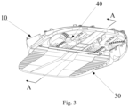
Fig. 3 is a perspective diagram of a cleaning base station with base station frame structure being removed according to an exemplary embodiment of the present disclosure; -
Fig. 4 is an exploded view ofFig. 3 ; -
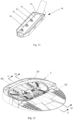
Fig. 5 (A) is a cross-sectional view taken along line A-A inFig. 3 ;Fig. 5 (B) is an enlarged view of portion H inFig. 5 (A) ; -
Fig. 6 is a schematic diagram ofFig. 5 with draining structure being removed; -
Fig. 7 is a perspective diagram of a sewage collecting body inFig. 4 from another angle; -
Fig. 8 is a cross-sectional view of a cleaning body inFig. 4 taken along line B-B; -
Fig. 9 is an exploded view of a draining structure inFig. 4 ; -
Fig. 10 (A) and 10 (B) is perspective diagrams of an elastic connector inFig. 9 ; -
Fig. 11 is a perspective diagram of a water supplying structure inFig. 4 ; -
Fig. 12 is a perspective diagram of a cleaning base station with base station frame structure being removed according to an exemplary embodiment of the present disclosure; -
Fig. 13 is an exploded view ofFig. 12 ; -
Fig. 14 is a cross-sectional view ofFig. 12 taken along line C-C; -
Fig. 15 is a cross-sectional view ofFig. 12 taken along line D-D, with the cleaning body being removed; -
Fig. 16 is a cross-sectional view of a sewage collecting body inFig. 13 taken along line E-E; -
Fig. 17 is a perspective diagram of a cleaning base station with base station frame structure being removed according to an exemplary embodiment of the present disclosure; -
Fig. 18 is an exploded view ofFig. 17 ; -
Fig. 19 is a cross-sectional view ofFig. 17 taken along line F-F, with the cleaning body being removed; -
Fig. 20 is an enlarged view of portion G inFig. 19 ; -
Fig. 21 is a perspective diagram of a water supplying structure inFig. 18 ; -
Fig. 22 is an exploded view of the water supplying structure inFig. 21 ; -
Fig. 23 is a perspective diagram of a cleaning base station with base station frame structure being removed according to an exemplary embodiment of the present disclosure; -
Fig. 24 is an exploded view ofFig. 23 ; and -
Fig. 25 is a perspective diagram of a water supplying pipe according to an exemplary embodiment of the present disclosure. - In order to explain in detail the technical content, construction features, the purpose and effect achieved by the present disclosure, the following combined with the embodiment and the attached drawings are described in detail.
- The present disclosure provides a
cleaning base station 1 used in cooperation with a cleaning robot to clean cleaning members of cleaning robots. The cleaning members may be mops, brushes, etc.. It should be noted that, the cleaning base station in the disclosure is not limited to merely clean cleaning robots, it can also clean handheld cleaning devices or mops or brushes that are manually used by users. - Referring to
Fig. 2 to Fig. 5 , in some embodiments, thecleaning base station 1 includes a basestation frame structure 10, a drainingstructure 20, asewage collecting body 30, and acleaning body 40. The basestation frame structure 10 includes afirst assembling portion 11a/11b/11c/11d. The drainingstructure 20 is arranged on the basestation frame structure 10, and includes adrainage channel structure 21. Referring toFig. 4 to Fig. 7 , thesewage collecting body 30 includes asewage collecting portion 31, awater outlet 32A, and asecond assembling portion 33a/33b/33c/33d. Thesecond assembling portion 33a/33b/33c/33d cooperates with thefirst assembling portion 11a/11b/11c/11d to limit thesewage collecting body 30 on the basestation frame structure 10. Referring toFig. 5(A) and Fig. 5(B) , thewater outlet 32A is communicated with thesewage collecting portion 31, and is detachably connected with thedrainage channel structure 21. The cleaningbody 40 is arranged on thesewage collecting body 30, and the cleaningbody 40 is defined with filteringholes 41 communicated with thesewage collecting portion 31. In an exemplary embodiment, the basestation frame structure 10 may include a first limitingportion 12, and the drainingstructure 20 is limited by the first limitingportion 12. The cleaning member is cleaned on the cleaningbody 40, sewage generated during cleaning the cleaning member flows to thesewage collecting portion 31 of thesewage collecting body 30 through the filtering holes 41, and then flows into the drainingstructure 20 through thewater outlet 32A of thesewage collecting body 30, while solid impurities will be deposited on the cleaningbody 40 and thesewage collecting body 30. The entire cleaning process is performed on the cleaningbody 40 and thesewage collecting body 30, and sewage and solid impurities will not run to the basestation frame structure 10, such that it can maintain the cleanliness of the basestation frame structure 10. In some exemplary embodiments, thefirst assembling portion 11a/11b/11c/11d is arranged on aninner side wall 13 of the basestation frame structure 10. Thesewage collecting body 30 may be a plate-shaped structure, thesewage collecting portion 31 is located on an upper surface of thesewage collecting body 30, thewater outlet 32A is arranged on a lower surface of thesewage collecting body 30, and thesecond assembling portion 33a/33b/33c/33d is arranged on a side edge of thesewage collecting body 30. During thesewage collecting body 30 being assembled to the basestation frame structure 10 along a direction from top to bottom or a direction from front to back, thesecond assembling portion 33a/33b/33c/33d is guided by and aligned with thefirst assembling portion 11a/11b/11c/11d to finally complete the assembly, while thewater outlet 32A is detachably connected to thedrainage channel structure 21, as such thesewage collecting body 30 is limited in the basestation frame structure 10. In some embodiments, as shown inFig. 13 andFig. 18 , thefirst assembling portion 11a'/11b'/11c'/11d', 11a"/11b"/11c"/11d" can also be arranged onside wall 13', 13" andbottom wall 14', 14" of the basestation frame structure 10', 10", correspondingly, thesecond assembling portion 33a'/33b'/33c'/33d', 33a"/33b"/33c"/33d" can also be arranged on a lower surface of thesewage collecting body 30', 30". In some exemplary embodiments, thefirst assembling portion 11a/11b/11c/11d, 11a'11b'11c'11d', 11a"/11b"/11c"/11d" and thesecond assembling portion 33a/33b/33c/33d, 33a'/33b'/33c'/33d', 33a"/33b"/33c"/33d" can be flat surfaces, curved surfaces, or special-shaped surfaces matched with each other, and can also be a coupled structure like block (or clasp) and slot (or hole), as long as the sewage collecting body can be limited in the base station frame structure. In an exemplary embodiment, thesewage collecting body 30 is located below the cleaningbody 40, and sewage flows through the filtering holes 42 to thesewage collecting body 30. In some embodiments, thesewage collecting body 30 and the cleaningbody 40 may be arranged along a horizontal direction, as long as sewage can flow from the cleaningbody 40 to thesewage collecting body 30. When thesewage collecting body 30 is subjected to an external force and thewater outlet 32A is separated from thedrainage channel structure 21, thesecond assembling portion 33a/33b/33c/33d and thefirst assembling portion 11a/11b/11c/11d will also be separated from each other because of the external force, that is, thesewage collecting body 30 can be disassembled from the basestation frame structure 10. - In the embodiments described above, the cleaning
body 40 is arranged on thesewage collecting body 30, and thesewage collecting body 30 can be disassembled from the basestation frame structure 10. Solid impurities introduced during the cleaning process will be deposited on the cleaningbody 40 and thesewage collecting body 30, and after the cleaning is completed, both thesewage collecting body 30 and the cleaningbody 40 can be disassembled from the basestation frame structure 10 to be washed directly by tap water, which is very convenient since it does not need users to bend down and wipe the basestation frame structure 10 again and again. Therefore, thecleaning base station 1 can be cleaned conveniently, the cleaning process becomes more labor-saving and simple, and the using experience can be greatly improved. - In some embodiments, as shown in
Fig. 5(A) , Fig. 5(B) andFig. 9 , the drainingstructure 20 further includes anelastic connector 22 sleeved on one end of thedrainage channel structure 21, and thewater outlet 32A of thesewage collecting body 30 is connected to thedrainage channel structure 21 through theelastic connector 22. Theelastic connector 22 can ensure a sealing among thewater outlet 32A, thedrainage channel structure 21, and theelastic connector 22 benefiting from an elastic properties of theelastic connector 22. Therefore, sewage can be prevented from leaking to the basestation frame structure 10 and even to the outside of thecleaning base station 1, so as to avoid polluting the use environment of thecleaning base station 1 as much as possible. - In some embodiments, as shown in
Fig. 5(A), Fig. 5(B) ,Fig. 7 ,Fig. 9, Fig. 10(A) and Fig. 10(B) , thesewage collecting body 30 further includes apipe 32B connecting to thesewage collecting portion 31, and thewater outlet 32A is located at an end of thepipe 32B. Theelastic connector 22 includes a first connectingportion 221, a second connectingportion 222, and afiltering part 223, the first connectingportion 221 is sleeved on an outer peripheral wall of thepipe 32B, the second connectingportion 222 is sleeved on an outer peripheral wall of thedrainage channel structure 21, and thefiltering part 223 is located between thewater outlet 32A and thedrainage channel structure 21. Since thefiltering part 223 is arranged between thewater outlet 32A and thedrainage channel structure 21, large solid impurities introduced by cleaning the cleaning member can stay on thesewage collecting body 30 to not enter into thedrainage channel structure 21, as such, thedrainage channel structure 21 will not be blocked off by the large solid impurities, and damages to other components downstream of the water flow on thecleaning base station 1 can also be avoided as much as possible. - In some embodiments, as shown in
Fig. 6 andFig. 9 , the first limitingportion 12 defines a limitinggroove 121 and a receivinggroove 122, the limitinggroove 121 and the receivinggroove 122 are spaced by awall 123, and a first throughhole 124 is defined in thewall 123 to communicate with the limitinggroove 121 and the receivinggroove 122. Theelastic connector 22 further includes afirst matching portion 224a/224b. Thedrainage channel structure 21 includes a guidingpipe 211, apositioning member 212, a connectingpipe 214, and anegative pressure adapter 213. The connectingpipe 214 has two ends with one connecting with the guidingpipe 211 and the other connecting with thenegative pressure adapter 213, and thepositioning member 212 is sleeved on an outer wall of the connectingpipe 214. An outer wall of the guidingpipe 211 is arranged with a first engaging portion 211A1/211A2 and a second engaging portion 211B1/211B2, the positioningmember 212 includes a second matching portion 212A1/212A2, the first engaging portion 211A1/211A2 is engaged with and limited by thefirst matching portion 224a/224b, and the second engaging portion 211B1/211B2 is engaged with and limited by the second matching portion 212A1/212A2, as such theelastic connector 22, the guidingpipe 211, and thepositioning pipe 212 are connected together. Theelastic connector 22, the guidingpipe 211, the connectingpipe 214, and thepositioning member 212 are all received and limited in the limitinggroove 121. Thenegative pressure adapter 213 is received and limited in the receivinggroove 122. Thenegative pressure adapter 213 includes ajoint portion 213a, and thenegative pressure adapter 213 is connected to the connectingpipe 214 through thejoint portion 213a. The positioningmember 212 further includes amain body portion 212B having two sides, one side of themain body portion 212B is connected with an auxiliary limiting portion 212C1, and the other side of themain body portion 212B is connected with an auxiliary limiting portion 212C2. The auxiliary limiting portions 212C1/212C2 are connected to and limited by an inner wall of the limitinggroove 121. Themain body portion 212B and the auxiliary limiting portions 212C1/212C2 cooperatively form a limiting space, and the connectingpipe 214 is limited in the limiting space. Thejoint portion 213a passes through the first throughhole 124 and extends into the limitinggroove 121 to connect with the connectingpipe 214. In an exemplary embodiment, sewage from thewater outlet 32A of thesewage collecting body 30 enters the connectingpipe 214 through the guidingpipe 211 after being filtered by thefiltering part 223 of thesewage collecting body 30, and then is discharged by thenegative pressure adapter 213. In some other embodiments, as shown inFig. 14 , the limiting groove and the receiving groove of the first limiting portion may directly communicate with each other and are positioned on different planes, for example, the different planes can be perpendicular to each other, presenting an L-shape; for being a more stable structure, thedrainage channel structure 21 may not include the guiding pipe, the connecting pipe, and the negative pressure adapter, but only a structure of a single pipe, with one end connecting to the elastic connector 22'. - In some embodiments, as shown in
Fig. 4 ,Fig. 13 andFig. 18 , in order to facilitate the cleaning, the cleaningbody sewage collecting body sewage collecting body third assembling portion 36a/36b/36c/36d, 36a'/36b'/36c'/36d', 36a"/36b"/36c"/36d", the cleaningbody fourth assembling portion 42a/42b/42c/42d, 42a'/42b'/42c'/42d', 42a"/42b"/42c"/42d" which is assembled with thethird assembling portion 36a/36b/36c/36d, 36a'/36b'/36c'/36d', 36a"/36b"/36c"/36d", allowing the cleaningbody sewage collecting body sewage collecting body 30 includes aside wall 35, thethird assembling portion 36a/36b/36c/36d is arranged on theside wall 35, the cleaningbody 40 is a plate-shaped structure, and thefourth assembling portion 42a/42b/42c/42d is arranged on a side edge of the cleaningbody 40. During thecleaning body 40 being assembled to thesewage collecting body 30 along a direction from top to bottom, thefourth assembling portion 42a/42b/42c/42d is guided by and aligned with thethird assembling portion 36a/36b/36c/36d until completing the assembly, allowing the cleaningbody 40 to be limited in thesewage collecting body 30. Optionally, the third assembling portion may also be arranged on a bottom wall of the sewage collecting body, and correspondingly, the fourth assembling portion may also be arranged on a lower side of the cleaning body. In some exemplary embodiments, the third assembling portion and the fourth assembling portion may be planes, curved surfaces, or special-shaped surfaces matched with each other, or may be a coupled structure of block (or clasp) and slot (or hole), as long as the cleaning body can be limited on the sewage collecting body. That is, the cleaning body and the sewage collecting body are detachably connected and can be separated from each other. Alternatively, the cleaning body and the sewage collecting body can also be movably connected, for example, one of the third assembling portion and the fourth assembling portion is a pivot structure and the other of the third assembling portion and the fourth assembling portion is a pivot bushing structure, or one of the third assembling portion and the fourth assembling portion is a sliding slot and the other of the third assembling portion and the fourth assembling portion is a slider. That is, the cleaning body and the sewage collecting body can rotate or flipped relative to each other through a pivot structure, or one can slide on another, which is not limited here. - In the embodiments described above, the sewage collecting body and the cleaning body are assembled by detachably or movably connecting, therefore, when solid impurities deposited on the sewage collecting body and the cleaning body are needed to be cleaned out, the cleaning body can be disassembled from the sewage collecting body, or can be moved relative to the sewage collecting body to expose the sewage collecting body, which makes the cleaning of the sewage collecting body and the cleaning body be more thoroughly and conveniently.
- In some embodiments, as shown in
Fig. 4 andFig. 18 , a periphery of the cleaningbody hem hem body body body structure Fig. 13 , the hem 50' can also be arranged around the sewage collecting body 30', as long as sewage splashing or overflowing from the cleaning base station can be prevented as much as possible, which is not limited here. - Referring to
Fig. 4 andFig. 18 again, the cleaningbody sewage guiding area sewage filtering area body sewage filtering area holes sewage guiding area vent vent vent sewage guiding area sewage filtering area vent vent Fig. 4 andFig. 13 , aconvex stage 60, 60' is provided in the middle of thesewage guiding area 43, 43', and each one of the left and right sides of theconvex stage 60, 60' is arranged with avent 61, 61'. By such an arrangement of thevents 61, 61', the airflow can be uniformly blown to the whole cleaning member. Further, in order to increase an air-drying speed of the cleaning member and the cleaning body, a heating device (not shown) is arranged at the vent, so that hot wind can be output from the vent to the sewage filtering area. In some embodiments, as shown inFig. 8 andFigs. 17-20 , the cleaningbody air passage vent rib plate 63, 63' in theair passage vents 61a/61b, 61a"/61b" located on both sides of the sewage guiding area. In some other embodiments, as shown inFig. 12 ,Fig. 13 andFig. 16 , vent 61' can also be arranged on the sewage collecting body 30', correspondingly, the cleaning body 40' is arranged at the front of the sewage collecting body 30', the convex stage 60' is arranged in the middle of the sewage collecting body 30' and is near to the cleaning body 40', and each one of the left and right sides of the convex stage 60' is defined with a vent 61'. Similarly, the sewage collecting body 30' is also provided with an air passage 62' that communicates with the vents 61', and a rib plate 63' is configured to distribute the airflow to the two vents 61' located on both sides of the sewage guiding area. - In some embodiments, as shown in
Fig. 4 , thesewage collecting portion 31 is provided with a converging structure 38 which is configured to collect sewage to the drainingstructure 20. The converging structure 38 includes aninclined surface 381 extended towards a joint of thesewage collecting portion 31 and thewater outlet 32A. A joint of thesewage collecting body 30 and the drainingstructure 20 corresponds to the lowest position of theinclined surface 381. In some instances, the converging structure 38 further includes a convergingsurface 382 located on thesewage collecting body 30, and located at the lowest point of theinclined surface 381. Theinclined surface 381 is arranged around the convergingsurface 382, extends towards the convergingsurface 382, and converges at the convergingsurface 382. In this embodiment, the sewage converging structure 38 is formed by theinclined surface 381 and the convergingsurface 382 arranged on thesewage collecting body 30, when sewage flows to theinclined surface 381, the sewage can automatically flow to the convergingsurface 382 below, such that the overflowing of the sewage on thesewage collecting body 30 can be reduced. - In some embodiments, the
inclined surface 381 extends towards the convergingsurface 382 along a circumferential direction and converges at the convergingsurface 382. Theinclined surface 381 may be an arc surface, a slant surface, or a special-shaped surface, which is not limited here. - In an exemplary embodiment, the converging structure 38 is directly defined by the
inclined surface 381 and the convergingsurface 382 which are arranged on thesewage collecting body 30, when sewage flows to theinclined surface 381, the sewage can automatically flow to the convergingsurface 382 below, such that the overflowing of the sewage on thesewage collecting body 30 can be reduced. - In some embodiments, as shown in
Fig. 23 and Fig. 24 , the cleaningbody 40‴ is further provided with agarbage collector 70, thegarbage collector 70 is arranged side by side with the cleaningbody 40‴ and communicated with the filtering holes 41‴ to collect the garbage flowing out through the filtering holes 41‴. Thegarbage collector 70 is detachably connected to the cleaningbody 40‴, such that it will be convenient to clean up the garbage accumulated in thegarbage collector 70, so as to avoid a blocking to the filtering holes 41‴, and facilitate the cleaning of the cleaningbody 40‴. - In some embodiments, as shown in
Fig. 4 , the cleaning base station includes a basestation frame structure 10 configured to support the cleaningbody 40, thesewage collecting body 30, and the drainingstructure 20. The cleaningbody 40 and thesewage collecting body 30 are configured to collect garbage and sewage, the converging structure 38 is configured to converge the sewage to the drainingstructure 20, and the drainingstructure 20 is configured to discharge the sewage, such that it can avoid an overflow of the sewage as much as possible. Further, the drainingstructure 20 is in a sealed connection with thesewage collecting body 30, so cleanliness of the basestation frame structure 10 during cleaning of the cleaning member is improved. The basestation frame structure 10 is detachably connected to thesewage collecting body 30, and the cleaningbody 40 and thesewage collecting body 30 are assembled together, so maintaining a cleanliness of the basestation frame structure 10, cleaning of the cleaningbody 40 and cleaning of thesewage collecting body 30 can be performed conveniently. In this embodiment, for cleaning the cleaning base station, it is only necessary to clean the disassembled cleaningbody 40 and the disassembledsewage collecting body 30, namely, it does not need to clean the wholecleaning base station 1, which improves the convenience of using the cleaning base station. - In some embodiments, as shown in
Fig. 4 ,Fig. 11 ,Fig. 13 ,Fig. 15 , andFigs. 18-22 , the basestation frame structure water supplying structure water supplying structure water supplying pipe water supplying outlet sewage collecting body first opening body second opening water supplying outlet first opening second opening water supplying outlet first opening second opening cleaning body cleaning base station 1. In another exemplary embodiment, the sewage collecting body 30' is provided with a first opening 39', and the water supplying outlet 82' and the first opening 39' are configured to be arranged correspondingly and communicated with each other. - In some embodiments, as shown in
Fig. 4 ,Fig. 13 , andFig. 18 , the sewage collecting body and/or the cleaning body includes an avoidance structure corresponding to the water supplying structure. In some exemplary embodiments, as shown inFigs. 4 and18 , thesewage collecting body first avoidance structure first opening first avoidance structure body second avoidance structure second opening second avoidance structure first avoidance structure water supplying pipe water supplying pipe second avoidance structure first avoidance structure first avoidance structure first avoidance structure 34 is a slotted structure, while taking into account the function of thefirst opening 39, that is, thefirst avoidance structure 34 can be thefirst opening 39. When the sewage collecting body is assembled on the base station frame structure, the first avoidance structure avoiding the water supplying pipe can allow the water supplying pipe supplying water smoothly, and the first avoidance structure can also limit a relative position between the sewage collecting body and the base station frame structure. Similarly, when the cleaning body is assembled on the sewage collecting body, the second avoidance structure avoids the first avoidance structure to allow the water supplying pipe supplying water smoothly, and the second avoidance structure can also limit a relative position between the cleaning body and the sewage collecting body. In some instances, the first avoidance structure and the second avoidance structure may be slots or openings penetrating the sewage collecting body or the cleaning body, or may be protruding structures adapted to the water supplying pipes, which is not limited here. In an exemplary embodiment, as shown inFig. 13 , the sewage collecting body 30' is provided with a first avoidance structure 34', and the first opening 39' is defined in the first avoidance structure 34'. The first avoidance structure 34' is configured to be arranged corresponding to the water supplying structure 80' to make way for the water supplying structure 80', and the first opening 39' is configured to be arranged corresponding to the water supplying outlet 82' to achieve smooth water supplying. - In some embodiments, as shown in
Figs. 4 ,11 ,13 , and18-22 , thewater supplying pipe sewage collecting portion wing water supplying pipe groove wing water supplying pipe water supplying pipe sewage collecting portion water supplying pipe water supplying structure water supplying pipe body water supplying pipe body body water supplying outlet water supplying pipe water supplying pipe water supplying pipe water supplying pipe station frame structure seat water supplying pipe seat sewage collecting body 30 is provided with a through hole communicating with the base station frame structure 10 (i.e., the above-mentioned first avoidance structure 34), a top of the mountingseat 15 passes through the through hole to locate above thesewage collecting body 30, and thewater supplying pipe 81 is installed on the top of the mountingseat 15. In some embodiments, as shown inFigs. 15 and19-20 , thesewage collecting body 30', 30" is further defined with adrainage outlet 341', 341", thedrainage outlet 341', 341" is arranged at one side of thefirst avoidance structure 34', 34" facing to thesewage collecting portion 31', 31", and is communicated with thefirst opening 39', 39". In case water flowing from thewater supplying outlets 82', 82" returns back, the water can flow to thesewage collecting portion 31', 31" through the first opening 39', 39' and thedrainage outlet 341', 341" in sequence, such that it can prevent sewage overflowing to the outside of the cleaning base station as much as possible. - In some embodiments, as shown in
Fig. 4 , the basestation frame structure 10 includes abottom wall 14, thebottom wall 14 is provided with abarrier rib 16 to allow thebottom wall 14 forming aclosed area 17, and thewater supplying pipe 81 is located in the closed area17. Thebarrier rib 16 is configured to prevent the water in theclosed area 17 flowing out of theclosed area 17. In some instances, thebarrier rib 16 is arranged around the mountingseat 15, so that the region where the mountingseat 15 is located forms theclosed area 17. Theclosed area 17 is arranged corresponding to thewater supplying pipe 81, allowing thewater supplying pipe 81 being located in theclosed area 17, that is, thewater supplying pipe 81 is closed in an enclosed space by theclosed area 17. Theclosed area 17 is also configured to receive the water flowing from thewater supplying pipe 81 to prevent the water flowing out of theclosed area 17 as much as possible, so as to define a dry and wet separation area on the basestation frame structure 10, which is in favor of maintaining the overall cleanliness of thebottom wall 14 of the basestation frame structure 10 and performing a local cleaning of the basestation frame structure 10. - In some embodiments, as shown in
Figs. 4 ,11 ,13 , and18-22 , thewater supplying pipe sewage collecting portion water supplying pipe wing water supplying pipe grooves wing water supplying pipe wing water supplying pipe groove wing water supplying pipe water supplying pipe groove water supplying pipe water supplying pipe wing baffle plate wing water supplying pipe groove baffle plate groove groove water supplying structure 80" further includes a sealingstructure 86" disposed between thewater supplying pipe 81" and thefirst avoidance structure 34", and the sealing structure 86' is configured to seal thefirst opening 39" on thefirst avoidance structure 34" to prevent the water flowing back from thewater supplying outlet 82', 82" from flowing back through thefirst opening 39" as much as possible, so as to ensure an sufficient amount of water that can be supplied to the cleaningbody 40" or the cleaning member. - In an exemplary embodiment, the pipe body of the
water supplying pipe 81"" is not limited to be obliquely arranged. In such a case, for ensuring the water returning from thewater supplying pipe 81"" being guided away, the water supplying structure may include other flow guiding structures, for example, a flow guiding member 83ʺʺ, which is configured to connect to the water supplying pipe 81ʺʺ. The flow guiding member 83ʺʺ is arranged obliquely, so the water flowing back from the water supplying pipe 81ʺʺ can at least partially flow to the flow guiding member 83ʺʺ and then flow outside along the flow guiding member 83ʺʺ. It can be merely an upper end of the flow guiding member 83ʺʺ being connected with an upper end of the water supplying pipe 81ʺʺ, which is not limited here. - While the disclosure has been described in connection with what are presently considered to be optional embodiments, it is to be understood that the disclosure is not to be limited to the disclosed embodiments, but on the contrary, is intended to cover various modifications and equivalent arrangement included within the scope of the disclosure.
Claims (14)
- A cleaning base station (1), configured for providing cleaning water to clean a cleaning member of a cleaning robot, and taking back sewage produced during cleaning the cleaning member, the cleaning base station (1) comprising:a base station frame structure (10, 10', 10") comprising a first assembling portion (11a/11b/11c/11d, lla' /11 b' /11 c' /11 d', 11a"/11b"/11c"/11d");a draining structure (20, 20', 20") arranged on the base station frame structure (10, 10', 10"), and the draining structure (20, 20', 20") comprising a drainage channel structure (21);a sewage collecting body (30, 30', 30") comprising:a sewage collecting portion (31, 31', 31");a second assembling portion (33a/33b/33c/33d, 33a'/33b'/33c'/33d', 33a"/33b"/33c"/33d") engaged with the first assembling portion (11a/11b/11c/11d, 11a'/11b'/11c'/11d',11a"/11b"/11c"/11d"), allowing the sewage collecting body (30, 30', 30") being assembled to and limited by the base station frame structure (10, 10', 10"); anda water outlet (32A) communicated with the sewage collecting portion (31, 31', 31"), and detachably connected with the drainage channel structure (21); anda cleaning body (40, 40', 40") arranged on the sewage collecting body (30, 30', 30"), and the cleaning body (40, 40', 40") defining a filtering hole (41, 40", 40‴) communicated with the sewage collecting portion (31, 31', 31"), characterized in that,the sewage collecting body (30, 30', 30") further comprises a third assembling portion (36a/36b/36c/36d, 36a'/36b'/36c'/36d', 36a"/36b"/36c"/36d"), and the cleaning body (40, 40', 40") comprises a fourth assembling portion (42a/42b/42c/42d, 42a'/42b'/42c'/42d', 42a"/42b"/42c"/42d") assembled with the third assembling portion (36a/36b/36c/36d, 36a'/36b'/36c'/36d', 36a"/36b"/36c"/36d"), allowing the cleaning body (40, 40', 40") to be limited in the sewage collecting body (30, 30', 30").
- The cleaning base station as claimed in claim 1, whereinthe first assembling portion (11a/11b/11c/11d, 11a'/11b'/111c'/11d', 11a"/11b"/11c"/11d") and the second assembling portion (33a/33b/33c/33d, 33a'/133b'/133c'/133d', 33a"/33b"/33c"/33d") are planes, curved surfaces, or special-shaped surfaces matched with each other; orone of the first assembling portion (11a/11b/11c/11d, 11a'/11b'/11c'/11d', 11a"11b"11c"11d") and the second assembling portion (33a/33b/33c/33d, 33a'/33b'/33c'/33d', 33a"/33b"/33c"/33d") is a block or a clasp structure, and the other of the first assembling portion (11a/11b/11c/11d, 11a'/11b'/11c'/11d', 11a"/11b"/11c"/11d") and the second assembling portion (33a/33b/33c/33d, 33a'/33b'/33c'/33d', 33a"/33b"/33c"/33d") is a slot or a hole structure.
- The cleaning base station (1) as claimed in claim 1, wherein the draining structure (20) further comprises an elastic connector (22) sleeved on an end of the drainage channel structure (21), and the water outlet (32A) is connected to the drainage channel structure (21) through the elastic connector (22).
- The cleaning base station (1) as claimed in claim 3, wherein the sewage collecting body (30) further comprises a pipe (32B) connected to the sewage collecting portion (31), and the water outlet (32A) is located at an end of the pipe (32B);
the elastic connector (22) comprises:a first connecting portion (221) sleeved on an outer peripheral wall of the pipe (32B);a second connecting portion (222) sleeved on an outer peripheral wall of the drainage channel structure (21); anda filtering part (223) located between the water outlet (32A) and the drainage channel structure (21). - The cleaning base station (1) as claimed in claim 1, whereinthe third assembling portion (36a/36b/36c/36d, 36a'/36b'/36c'/36d', 36a"/36b"/36c"/36d") and the fourth assembling portion (42a/42b/42c/42d, 42a'/42b'/42c'/42d', 42a"/42b"/42c"/42d") are planes, curved surfaces, or special-shaped surfaces matched with each other; orone of the third assembling portion (36a/36b/36c/36d, 36a'/36b'/36c'/36d', 36a"/36b"/36c"/36d") and the fourth assembling portion (42a/42b/42c/42d, 42a'/42b'/42c'/42d', 42a"/42b"/42c"/42d") is a block or a clasp structure, and the other of the third assembling portion (36a/36b/36c/36d, 36a'/36b'/36c'/36d', 36a"/36b"/36c"/36d") and the fourth assembling portion (42a/42b/42c/42d, 42a'/42b'/42c'/42d', 42a"/42b"/42c"/42d") is a slot or a hole structure; orone of the third assembling portion (36a/36b/36c/36d, 36a'/36b'/36c'/36d', 36a"/36b"/36c"/36d") and the fourth assembling portion (42a/42b/42c/42d, 42a'/42b'/42c'/42d', 42a"/42b"/42c"/42d") is a pivot structure, and the other of the third assembling portion (36a/36b/36c/36d, 36a'/36b'/36c'/36d', 36a"/36b"/36c"/36d") and the fourth assembling portion (42a/42b/42c/42d, 42a'/42b'/42c'/42d', 42a"/42b"/42c"/42d") is a pivot bushing structure; orone of the third assembling portion (36a/36b/36c/36d, 36a'/36b'/36c'/36d', 36a"/36b"/36c"/36d") and the fourth assembling portion (42a/42b/42c/42d, 42a'/42b'/42c'/42d', 42a"/42b"/42c"/42d") is a sliding slot and the other of the third assembling portion (36a/36b/36c/36d, 36a'/36b'/36c'/36d', 36a"/36b"/36c"/36d") and the fourth assembling portion (42a/42b/42c/42d, 42a'/42b'/42c'/42d', 42a"/42b"/42c"/42d") is a slider.
- The cleaning base station (1) as claimed in claim 1, wherein the base station frame structure (10, 10', 10") is provided with a water supplying structure (80, 80', 80"), and the water supplying structure (80, 80', 80") comprises a water supplying pipe (81, 81', 81") defined with a water supplying outlet (82, 82', 82");
the sewage collecting body (30, 30', 30") and/or the cleaning body (40, 40', 40") is provided with an opening configured for communicating with the water supplying outlet (82, 82', 82"). - The cleaning base station (1) as claimed in claim 1, wherein the sewage collecting body (30, 30") is defined with a first opening (39, 39"), the cleaning body (40, 40") is defined with a second opening (45, 45"), and the water supplying outlet (82, 82"), the first opening (39, 39") and the second opening (45, 45") are configured to be arranged correspondingly and communicate with each other; or
the sewage collecting body (30, 30', 30") is defined with a first opening (39, 39', 39"), and the water supplying outlet (82, 82', 82") and the first opening (39, 39', 39") are configured to be arranged correspondingly and communicate with each other. - The cleaning base station (1) as claimed in claim 6, wherein the sewage collecting body (30, 30', 30") and/or the cleaning body (40, 40', 40") comprises an avoidance structure arranged corresponding to the water supplying structure (80, 80', 80") to make way for the water supplying pipe (81, 81', 81").
- The cleaning base station (1) as claimed in claim 6, wherein the sewage collecting body (30, 30") is defined with a first avoidance structure (34, 34"), the first opening (39, 39") is defined on the first avoidance structure (34, 34"), and the first avoidance structure (34, 34") is located above the water supplying pipe (81, 81") to make way for the water supplying pipe (81, 81"); and
the cleaning body (40, 40") is provided with a second avoidance structure (46, 46"), the second opening (45, 45") is defined on the second avoidance structure (46, 46"), and the second avoidance structure (46, 46") is located above the first avoidance structure (34, 34") to make way for the first avoidance structure (34, 34") or the water supplying pipe (81, 81"). - The cleaning base station (1) as claimed in claim 6, wherein the water supplying pipe (81, 81', 81") is arranged obliquely towards the sewage collecting portion (31, 31', 31"), the water supplying pipe (81, 81', 81") is provided with a wing (83, 83', 83") extended along an inclined direction of the water supplying pipe (81, 81', 81"), and a guiding groove (84, 84', 84") is defined between the wing (83, 83', 83") and the water supplying pipe (81, 81', 81").
- The cleaning base station (1) as claimed in claim 6, wherein a baffle plate (85, 85', 85") is provided at a higher end of the water supplying pipe (81, 81', 81"), the baffle plate (85, 85', 85") is connected with the wing (83, 83', 83"), and is configured to block off the higher end of the water supplying pipe (81, 81', 81").
- The cleaning base station (1) as claimed in claim 8, wherein the water supplying structure (80") further comprises a sealing structure (86") arranged between the water supplying pipe (81") and the avoidance structure.
- The cleaning base station (1) as claimed in claim 6, wherein the water supplying pipe (81"") is connected with a flow guiding member (83"") which is arranged obliquely, and the flow guiding member (83"") is configured to guide the water flowing back from the water supplying pipe (81"") and make the water flow outside along the flow guiding member (83" "").
- The cleaning base station (1) as claimed in claim 1, wherein the cleaning body (40, 40', 40") is defined with a vent hole (61, 61', 61") communicated with the filtering hole (41, 41', 41"), and a height of the vent hole (61, 61', 61") is higher than that of the filtering hole (41, 41', 41").
Applications Claiming Priority (1)
| Application Number | Priority Date | Filing Date | Title |
|---|---|---|---|
| CN202110487687.6A CN113180559A (en) | 2021-04-30 | 2021-04-30 | Cleaning base station |
Publications (2)
| Publication Number | Publication Date |
|---|---|
| EP4082417A1 EP4082417A1 (en) | 2022-11-02 |
| EP4082417B1 true EP4082417B1 (en) | 2023-11-15 |
Family
ID=76983477
Family Applications (1)
| Application Number | Title | Priority Date | Filing Date |
|---|---|---|---|
| EP22171053.6A Active EP4082417B1 (en) | 2021-04-30 | 2022-04-29 | Cleaning base station |
Country Status (3)
| Country | Link |
|---|---|
| US (1) | US20220346619A1 (en) |
| EP (1) | EP4082417B1 (en) |
| CN (1) | CN113180559A (en) |
Families Citing this family (21)
| Publication number | Priority date | Publication date | Assignee | Title |
|---|---|---|---|---|
| CN115474872A (en) * | 2021-06-15 | 2022-12-16 | 深圳银星智能集团股份有限公司 | Maintenance stations and cleaning systems |
| CN115707422A (en) * | 2021-08-18 | 2023-02-21 | 美智纵横科技有限责任公司 | Base station for cleaning equipment and cleaning system |
| CN216317428U (en) * | 2021-08-20 | 2022-04-19 | 北京石头世纪科技股份有限公司 | Base station and cleaning robot system |
| CN116115130A (en) * | 2021-09-30 | 2023-05-16 | 添可智能科技有限公司 | Cleaning system, cleaning device and cleaning method |
| US12507852B2 (en) | 2021-11-13 | 2025-12-30 | Shenzhen Silver Star Intelligent Group Co., Ltd. | Cleaning base station and cleaning system |
| CN114271732A (en) * | 2021-12-21 | 2022-04-05 | 深圳市优必选科技股份有限公司 | Base station and cleaning robot system |
| CN116350124A (en) * | 2021-12-28 | 2023-06-30 | 美智纵横科技有限责任公司 | Base station for cleaning equipment and cleaning system |
| USD1044183S1 (en) * | 2022-03-14 | 2024-09-24 | Anker Innovations Technology Co., Ltd. | Dust collection station |
| US12194508B2 (en) * | 2022-08-01 | 2025-01-14 | Irobot Corporation | Cleaning pad washing |
| CN115316897A (en) * | 2022-08-03 | 2022-11-11 | 昆山鑫泰利智能科技股份有限公司 | Sewage tank based on floor cleaning machine basic station |
| CN115191891A (en) * | 2022-08-03 | 2022-10-18 | 昆山鑫泰利智能科技股份有限公司 | Back suction air duct based on floor cleaning machine base station |
| KR20250065866A (en) * | 2022-09-14 | 2025-05-13 | 메이디 로보존 테크놀러지 컴퍼니 리미티드 | Cleaning base station for cleaning equipment and cleaning system equipped therewith |
| WO2024139093A1 (en) * | 2022-12-30 | 2024-07-04 | 北京石头世纪科技股份有限公司 | Cleaning base station and cleaning system |
| CN116530896A (en) * | 2023-04-19 | 2023-08-04 | 深圳市杉川机器人有限公司 | Base station and cleaning equipment |
| CN117652958A (en) * | 2023-12-05 | 2024-03-08 | 深圳市杉川机器人有限公司 | Base station sink structure, base station, cleaning robot and cleaning equipment |
| USD1096034S1 (en) * | 2023-12-29 | 2025-09-30 | Yunjing Intelligence Innovation (Shenzhen) Co., Ltd. | Base station for cleaning robot |
| DE202024103778U1 (en) * | 2024-01-05 | 2024-07-22 | Beijing Roborock Technology Co., Ltd. | Cleaning station and cleaning system |
| TW202537580A (en) * | 2024-03-25 | 2025-10-01 | 大陸商北京石頭世紀科技股份有限公司 | Cleaning base stations and cleaning systems |
| WO2025201301A1 (en) * | 2024-03-25 | 2025-10-02 | 北京石头世纪科技股份有限公司 | Cleaning base station and cleaning system |
| TW202543539A (en) * | 2024-03-25 | 2025-11-16 | 大陸商北京石頭世紀科技股份有限公司 | Cleaning base stations and cleaning systems |
| CN223232648U (en) * | 2024-09-29 | 2025-08-19 | 北京小米移动软件有限公司 | Cleaning trays, base stations, and cleaning systems |
Family Cites Families (15)
| Publication number | Priority date | Publication date | Assignee | Title |
|---|---|---|---|---|
| AU2018203547B2 (en) * | 2017-06-02 | 2023-09-28 | Bissell Inc. | Self-cleaning system and method for extraction cleaners |
| CN108703719A (en) * | 2018-05-29 | 2018-10-26 | 宁波富佳实业有限公司 | A kind of integrated form cleaning device |
| CN109091084A (en) * | 2018-11-09 | 2018-12-28 | 攀枝花学院 | A kind of separate type floor-cleaning machine |
| US20220000327A1 (en) * | 2018-11-19 | 2022-01-06 | Shanghai Nanmu Robot Technology Co., Ltd. | Robot cleaner and automatic cleaning method |
| CN109528111B (en) * | 2018-12-28 | 2024-08-16 | 云鲸智能科技(东莞)有限公司 | Base Station |
| CN119138807A (en) * | 2018-12-28 | 2024-12-17 | 云鲸智能创新(深圳)有限公司 | Base station |
| JP3239433U (en) * | 2019-10-22 | 2022-10-13 | 嘉▲興▼福特塑料▲電▼器有限公司 | Mop cloth cleaning device for electric mop cleaner |
| CN110881911B (en) * | 2019-12-20 | 2025-03-25 | 深圳银星智能集团股份有限公司 | Cleaning Equipment |
| CN212118058U (en) * | 2019-12-20 | 2020-12-11 | 深圳市银星智能科技股份有限公司 | Cleaning device |
| CN111493768A (en) * | 2020-05-20 | 2020-08-07 | 深圳市杉川机器人有限公司 | cleaning device |
| CN115067835B (en) * | 2020-08-20 | 2024-11-26 | 科沃斯机器人股份有限公司 | Cleaning device and cleaning robot system |
| CN112535440B (en) * | 2020-08-30 | 2024-07-16 | 杭州匠龙机器人科技有限公司 | Cleaning robot with cleaning seat |
| CN112089367A (en) * | 2020-10-09 | 2020-12-18 | 深圳市诚忆智能科技有限公司 | Floor cleaning system and electric mop cleaning method |
| CN112353318B (en) * | 2020-11-13 | 2025-10-21 | 杭州匠龙机器人科技有限公司 | A control method for a cleaning robot system |
| CN112401762A (en) * | 2020-11-20 | 2021-02-26 | 杭州匠龙机器人科技有限公司 | An integration station and its cleaning robot system |
-
2021
- 2021-04-30 CN CN202110487687.6A patent/CN113180559A/en active Pending
-
2022
- 2022-04-29 EP EP22171053.6A patent/EP4082417B1/en active Active
- 2022-04-29 US US17/733,342 patent/US20220346619A1/en not_active Abandoned
Also Published As
| Publication number | Publication date |
|---|---|
| EP4082417A1 (en) | 2022-11-02 |
| US20220346619A1 (en) | 2022-11-03 |
| CN113180559A (en) | 2021-07-30 |
Similar Documents
| Publication | Publication Date | Title |
|---|---|---|
| EP4082417A1 (en) | Cleaning base station | |
| EP3741278B1 (en) | Dust collection box and sweeping robot | |
| CN215899556U (en) | Slop pail, separation structure, ground washing assembly and ground washing machine | |
| CN214549280U (en) | A self-cleaning washing machine | |
| CN109124479A (en) | Dust catcher | |
| CN214073161U (en) | Multifunctional service station, sweeping robot system | |
| CN215078126U (en) | Dirt collection box assembly, maintenance base station and cleaning system | |
| CN218899339U (en) | Convenient clear from album dirt clean system | |
| CN114424905A (en) | Multifunctional service station, floor sweeping robot system and control method thereof | |
| CN111065305A (en) | Surface cleaner | |
| CN218684125U (en) | Cleaning device | |
| WO2019001545A1 (en) | Vacuum cleaner | |
| US12171394B2 (en) | Dirt collecting box assembly, maintenance station and cleaning system | |
| SK284746B6 (en) | Suction device attachment for wet cleaning surfaces | |
| CN223183468U (en) | cleaning equipment | |
| CN222787660U (en) | Cleaning equipment, base stations and cleaning systems | |
| CN114587214A (en) | Self-cleaning dust collector and dust collection system | |
| CN114587213A (en) | Self-cleaning dust collector and dust collection system | |
| CN114947638B (en) | Automatic cleaning wet-type surface cleaning device | |
| CN216495159U (en) | Self-cleaning dust collecting seat and dust collecting system | |
| CN215738687U (en) | Dust collector | |
| CN121081973A (en) | Water tank body assembly and water tank capable of continuously feeding and discharging water | |
| CN223220401U (en) | Dirt collection tanks and cleaning equipment | |
| CN210128478U (en) | Auxiliary cleaning device and air conditioner | |
| CN223453169U (en) | Cleaning system, cleaning service station and cleaning robot |
Legal Events
| Date | Code | Title | Description |
|---|---|---|---|
| PUAI | Public reference made under article 153(3) epc to a published international application that has entered the european phase |
Free format text: ORIGINAL CODE: 0009012 |
|
| STAA | Information on the status of an ep patent application or granted ep patent |
Free format text: STATUS: REQUEST FOR EXAMINATION WAS MADE |
|
| 17P | Request for examination filed |
Effective date: 20220429 |
|
| AK | Designated contracting states |
Kind code of ref document: A1 Designated state(s): AL AT BE BG CH CY CZ DE DK EE ES FI FR GB GR HR HU IE IS IT LI LT LU LV MC MK MT NL NO PL PT RO RS SE SI SK SM TR |
|
| STAA | Information on the status of an ep patent application or granted ep patent |
Free format text: STATUS: EXAMINATION IS IN PROGRESS |
|
| 17Q | First examination report despatched |
Effective date: 20230201 |
|
| GRAP | Despatch of communication of intention to grant a patent |
Free format text: ORIGINAL CODE: EPIDOSNIGR1 |
|
| STAA | Information on the status of an ep patent application or granted ep patent |
Free format text: STATUS: GRANT OF PATENT IS INTENDED |
|
| INTG | Intention to grant announced |
Effective date: 20230707 |
|
| GRAS | Grant fee paid |
Free format text: ORIGINAL CODE: EPIDOSNIGR3 |
|
| GRAA | (expected) grant |
Free format text: ORIGINAL CODE: 0009210 |
|
| STAA | Information on the status of an ep patent application or granted ep patent |
Free format text: STATUS: THE PATENT HAS BEEN GRANTED |
|
| AK | Designated contracting states |
Kind code of ref document: B1 Designated state(s): AL AT BE BG CH CY CZ DE DK EE ES FI FR GB GR HR HU IE IS IT LI LT LU LV MC MK MT NL NO PL PT RO RS SE SI SK SM TR |
|
| RAP3 | Party data changed (applicant data changed or rights of an application transferred) |
Owner name: YUNJING INTELLIGENCE (SHENZHEN) CO., LTD. Owner name: YUNJING INTELLIGENCE INNOVATION (SHENZHEN) CO., LTD. |
|
| REG | Reference to a national code |
Ref country code: CH Ref legal event code: EP Ref country code: GB Ref legal event code: FG4D |
|
| P01 | Opt-out of the competence of the unified patent court (upc) registered |
Effective date: 20231019 |
|
| REG | Reference to a national code |
Ref country code: DE Ref legal event code: R096 Ref document number: 602022000986 Country of ref document: DE |
|
| REG | Reference to a national code |
Ref country code: IE Ref legal event code: FG4D |
|
| REG | Reference to a national code |
Ref country code: LT Ref legal event code: MG9D |
|
| REG | Reference to a national code |
Ref country code: NL Ref legal event code: MP Effective date: 20231115 |
|
| PG25 | Lapsed in a contracting state [announced via postgrant information from national office to epo] |
Ref country code: GR Free format text: LAPSE BECAUSE OF FAILURE TO SUBMIT A TRANSLATION OF THE DESCRIPTION OR TO PAY THE FEE WITHIN THE PRESCRIBED TIME-LIMIT Effective date: 20240216 |
|
| PG25 | Lapsed in a contracting state [announced via postgrant information from national office to epo] |
Ref country code: IS Free format text: LAPSE BECAUSE OF FAILURE TO SUBMIT A TRANSLATION OF THE DESCRIPTION OR TO PAY THE FEE WITHIN THE PRESCRIBED TIME-LIMIT Effective date: 20240315 |
|
| PG25 | Lapsed in a contracting state [announced via postgrant information from national office to epo] |
Ref country code: LT Free format text: LAPSE BECAUSE OF FAILURE TO SUBMIT A TRANSLATION OF THE DESCRIPTION OR TO PAY THE FEE WITHIN THE PRESCRIBED TIME-LIMIT Effective date: 20231115 |
|
| REG | Reference to a national code |
Ref country code: AT Ref legal event code: MK05 Ref document number: 1630969 Country of ref document: AT Kind code of ref document: T Effective date: 20231115 |
|
| PG25 | Lapsed in a contracting state [announced via postgrant information from national office to epo] |
Ref country code: NL Free format text: LAPSE BECAUSE OF FAILURE TO SUBMIT A TRANSLATION OF THE DESCRIPTION OR TO PAY THE FEE WITHIN THE PRESCRIBED TIME-LIMIT Effective date: 20231115 |
|
| PG25 | Lapsed in a contracting state [announced via postgrant information from national office to epo] |
Ref country code: AT Free format text: LAPSE BECAUSE OF FAILURE TO SUBMIT A TRANSLATION OF THE DESCRIPTION OR TO PAY THE FEE WITHIN THE PRESCRIBED TIME-LIMIT Effective date: 20231115 |
|
| PG25 | Lapsed in a contracting state [announced via postgrant information from national office to epo] |
Ref country code: ES Free format text: LAPSE BECAUSE OF FAILURE TO SUBMIT A TRANSLATION OF THE DESCRIPTION OR TO PAY THE FEE WITHIN THE PRESCRIBED TIME-LIMIT Effective date: 20231115 |
|
| PG25 | Lapsed in a contracting state [announced via postgrant information from national office to epo] |
Ref country code: NL Free format text: LAPSE BECAUSE OF FAILURE TO SUBMIT A TRANSLATION OF THE DESCRIPTION OR TO PAY THE FEE WITHIN THE PRESCRIBED TIME-LIMIT Effective date: 20231115 Ref country code: LT Free format text: LAPSE BECAUSE OF FAILURE TO SUBMIT A TRANSLATION OF THE DESCRIPTION OR TO PAY THE FEE WITHIN THE PRESCRIBED TIME-LIMIT Effective date: 20231115 Ref country code: IS Free format text: LAPSE BECAUSE OF FAILURE TO SUBMIT A TRANSLATION OF THE DESCRIPTION OR TO PAY THE FEE WITHIN THE PRESCRIBED TIME-LIMIT Effective date: 20240315 Ref country code: GR Free format text: LAPSE BECAUSE OF FAILURE TO SUBMIT A TRANSLATION OF THE DESCRIPTION OR TO PAY THE FEE WITHIN THE PRESCRIBED TIME-LIMIT Effective date: 20240216 Ref country code: ES Free format text: LAPSE BECAUSE OF FAILURE TO SUBMIT A TRANSLATION OF THE DESCRIPTION OR TO PAY THE FEE WITHIN THE PRESCRIBED TIME-LIMIT Effective date: 20231115 Ref country code: BG Free format text: LAPSE BECAUSE OF FAILURE TO SUBMIT A TRANSLATION OF THE DESCRIPTION OR TO PAY THE FEE WITHIN THE PRESCRIBED TIME-LIMIT Effective date: 20240215 Ref country code: AT Free format text: LAPSE BECAUSE OF FAILURE TO SUBMIT A TRANSLATION OF THE DESCRIPTION OR TO PAY THE FEE WITHIN THE PRESCRIBED TIME-LIMIT Effective date: 20231115 Ref country code: PT Free format text: LAPSE BECAUSE OF FAILURE TO SUBMIT A TRANSLATION OF THE DESCRIPTION OR TO PAY THE FEE WITHIN THE PRESCRIBED TIME-LIMIT Effective date: 20240315 |
|
| PG25 | Lapsed in a contracting state [announced via postgrant information from national office to epo] |
Ref country code: SE Free format text: LAPSE BECAUSE OF FAILURE TO SUBMIT A TRANSLATION OF THE DESCRIPTION OR TO PAY THE FEE WITHIN THE PRESCRIBED TIME-LIMIT Effective date: 20231115 Ref country code: RS Free format text: LAPSE BECAUSE OF FAILURE TO SUBMIT A TRANSLATION OF THE DESCRIPTION OR TO PAY THE FEE WITHIN THE PRESCRIBED TIME-LIMIT Effective date: 20231115 Ref country code: PL Free format text: LAPSE BECAUSE OF FAILURE TO SUBMIT A TRANSLATION OF THE DESCRIPTION OR TO PAY THE FEE WITHIN THE PRESCRIBED TIME-LIMIT Effective date: 20231115 Ref country code: NO Free format text: LAPSE BECAUSE OF FAILURE TO SUBMIT A TRANSLATION OF THE DESCRIPTION OR TO PAY THE FEE WITHIN THE PRESCRIBED TIME-LIMIT Effective date: 20240215 Ref country code: LV Free format text: LAPSE BECAUSE OF FAILURE TO SUBMIT A TRANSLATION OF THE DESCRIPTION OR TO PAY THE FEE WITHIN THE PRESCRIBED TIME-LIMIT Effective date: 20231115 Ref country code: HR Free format text: LAPSE BECAUSE OF FAILURE TO SUBMIT A TRANSLATION OF THE DESCRIPTION OR TO PAY THE FEE WITHIN THE PRESCRIBED TIME-LIMIT Effective date: 20231115 |
|
| PG25 | Lapsed in a contracting state [announced via postgrant information from national office to epo] |
Ref country code: DK Free format text: LAPSE BECAUSE OF FAILURE TO SUBMIT A TRANSLATION OF THE DESCRIPTION OR TO PAY THE FEE WITHIN THE PRESCRIBED TIME-LIMIT Effective date: 20231115 |
|
| PG25 | Lapsed in a contracting state [announced via postgrant information from national office to epo] |
Ref country code: CZ Free format text: LAPSE BECAUSE OF FAILURE TO SUBMIT A TRANSLATION OF THE DESCRIPTION OR TO PAY THE FEE WITHIN THE PRESCRIBED TIME-LIMIT Effective date: 20231115 |
|
| PG25 | Lapsed in a contracting state [announced via postgrant information from national office to epo] |
Ref country code: SK Free format text: LAPSE BECAUSE OF FAILURE TO SUBMIT A TRANSLATION OF THE DESCRIPTION OR TO PAY THE FEE WITHIN THE PRESCRIBED TIME-LIMIT Effective date: 20231115 |
|
| PG25 | Lapsed in a contracting state [announced via postgrant information from national office to epo] |
Ref country code: SM Free format text: LAPSE BECAUSE OF FAILURE TO SUBMIT A TRANSLATION OF THE DESCRIPTION OR TO PAY THE FEE WITHIN THE PRESCRIBED TIME-LIMIT Effective date: 20231115 Ref country code: SK Free format text: LAPSE BECAUSE OF FAILURE TO SUBMIT A TRANSLATION OF THE DESCRIPTION OR TO PAY THE FEE WITHIN THE PRESCRIBED TIME-LIMIT Effective date: 20231115 Ref country code: RO Free format text: LAPSE BECAUSE OF FAILURE TO SUBMIT A TRANSLATION OF THE DESCRIPTION OR TO PAY THE FEE WITHIN THE PRESCRIBED TIME-LIMIT Effective date: 20231115 Ref country code: IT Free format text: LAPSE BECAUSE OF FAILURE TO SUBMIT A TRANSLATION OF THE DESCRIPTION OR TO PAY THE FEE WITHIN THE PRESCRIBED TIME-LIMIT Effective date: 20231115 Ref country code: EE Free format text: LAPSE BECAUSE OF FAILURE TO SUBMIT A TRANSLATION OF THE DESCRIPTION OR TO PAY THE FEE WITHIN THE PRESCRIBED TIME-LIMIT Effective date: 20231115 Ref country code: DK Free format text: LAPSE BECAUSE OF FAILURE TO SUBMIT A TRANSLATION OF THE DESCRIPTION OR TO PAY THE FEE WITHIN THE PRESCRIBED TIME-LIMIT Effective date: 20231115 Ref country code: CZ Free format text: LAPSE BECAUSE OF FAILURE TO SUBMIT A TRANSLATION OF THE DESCRIPTION OR TO PAY THE FEE WITHIN THE PRESCRIBED TIME-LIMIT Effective date: 20231115 |
|
| REG | Reference to a national code |
Ref country code: DE Ref legal event code: R097 Ref document number: 602022000986 Country of ref document: DE |
|
| PLBE | No opposition filed within time limit |
Free format text: ORIGINAL CODE: 0009261 |
|
| STAA | Information on the status of an ep patent application or granted ep patent |
Free format text: STATUS: NO OPPOSITION FILED WITHIN TIME LIMIT |
|
| 26N | No opposition filed |
Effective date: 20240819 |
|
| PG25 | Lapsed in a contracting state [announced via postgrant information from national office to epo] |
Ref country code: SI Free format text: LAPSE BECAUSE OF FAILURE TO SUBMIT A TRANSLATION OF THE DESCRIPTION OR TO PAY THE FEE WITHIN THE PRESCRIBED TIME-LIMIT Effective date: 20231115 |
|
| PG25 | Lapsed in a contracting state [announced via postgrant information from national office to epo] |
Ref country code: SI Free format text: LAPSE BECAUSE OF FAILURE TO SUBMIT A TRANSLATION OF THE DESCRIPTION OR TO PAY THE FEE WITHIN THE PRESCRIBED TIME-LIMIT Effective date: 20231115 |
|
| PG25 | Lapsed in a contracting state [announced via postgrant information from national office to epo] |
Ref country code: MC Free format text: LAPSE BECAUSE OF FAILURE TO SUBMIT A TRANSLATION OF THE DESCRIPTION OR TO PAY THE FEE WITHIN THE PRESCRIBED TIME-LIMIT Effective date: 20231115 |
|
| PG25 | Lapsed in a contracting state [announced via postgrant information from national office to epo] |
Ref country code: MC Free format text: LAPSE BECAUSE OF FAILURE TO SUBMIT A TRANSLATION OF THE DESCRIPTION OR TO PAY THE FEE WITHIN THE PRESCRIBED TIME-LIMIT Effective date: 20231115 |
|
| PG25 | Lapsed in a contracting state [announced via postgrant information from national office to epo] |
Ref country code: LU Free format text: LAPSE BECAUSE OF NON-PAYMENT OF DUE FEES Effective date: 20240429 |
|
| REG | Reference to a national code |
Ref country code: BE Ref legal event code: MM Effective date: 20240430 |
|
| PG25 | Lapsed in a contracting state [announced via postgrant information from national office to epo] |
Ref country code: LU Free format text: LAPSE BECAUSE OF NON-PAYMENT OF DUE FEES Effective date: 20240429 |
|
| PG25 | Lapsed in a contracting state [announced via postgrant information from national office to epo] |
Ref country code: BE Free format text: LAPSE BECAUSE OF NON-PAYMENT OF DUE FEES Effective date: 20240430 |
|
| PG25 | Lapsed in a contracting state [announced via postgrant information from national office to epo] |
Ref country code: BE Free format text: LAPSE BECAUSE OF NON-PAYMENT OF DUE FEES Effective date: 20240430 |
|
| PG25 | Lapsed in a contracting state [announced via postgrant information from national office to epo] |
Ref country code: IE Free format text: LAPSE BECAUSE OF NON-PAYMENT OF DUE FEES Effective date: 20240429 |
|
| PGFP | Annual fee paid to national office [announced via postgrant information from national office to epo] |
Ref country code: DE Payment date: 20250411 Year of fee payment: 4 |
|
| PGFP | Annual fee paid to national office [announced via postgrant information from national office to epo] |
Ref country code: FR Payment date: 20250429 Year of fee payment: 4 |
|
| PG25 | Lapsed in a contracting state [announced via postgrant information from national office to epo] |
Ref country code: CY Free format text: LAPSE BECAUSE OF FAILURE TO SUBMIT A TRANSLATION OF THE DESCRIPTION OR TO PAY THE FEE WITHIN THE PRESCRIBED TIME-LIMIT; INVALID AB INITIO Effective date: 20220429 |
|
| PG25 | Lapsed in a contracting state [announced via postgrant information from national office to epo] |
Ref country code: HU Free format text: LAPSE BECAUSE OF FAILURE TO SUBMIT A TRANSLATION OF THE DESCRIPTION OR TO PAY THE FEE WITHIN THE PRESCRIBED TIME-LIMIT; INVALID AB INITIO Effective date: 20220429 |
|
| PG25 | Lapsed in a contracting state [announced via postgrant information from national office to epo] |
Ref country code: FI Free format text: LAPSE BECAUSE OF FAILURE TO SUBMIT A TRANSLATION OF THE DESCRIPTION OR TO PAY THE FEE WITHIN THE PRESCRIBED TIME-LIMIT Effective date: 20231115 |
|
| REG | Reference to a national code |
Ref country code: CH Ref legal event code: H13 Free format text: ST27 STATUS EVENT CODE: U-0-0-H10-H13 (AS PROVIDED BY THE NATIONAL OFFICE) Effective date: 20251125 |
|
| PG25 | Lapsed in a contracting state [announced via postgrant information from national office to epo] |
Ref country code: CH Free format text: LAPSE BECAUSE OF NON-PAYMENT OF DUE FEES Effective date: 20250430 |
|
| PGFP | Annual fee paid to national office [announced via postgrant information from national office to epo] |
Ref country code: GB Payment date: 20260325 Year of fee payment: 5 |