EP4080080A1 - Système de freinage pour un véhicule utilitaire, procédé d'application d'une force de freinage et véhicule utilitaire - Google Patents
Système de freinage pour un véhicule utilitaire, procédé d'application d'une force de freinage et véhicule utilitaire Download PDFInfo
- Publication number
- EP4080080A1 EP4080080A1 EP21170263.4A EP21170263A EP4080080A1 EP 4080080 A1 EP4080080 A1 EP 4080080A1 EP 21170263 A EP21170263 A EP 21170263A EP 4080080 A1 EP4080080 A1 EP 4080080A1
- Authority
- EP
- European Patent Office
- Prior art keywords
- transfer element
- brake actuator
- braking
- secondary brake
- braking system
- Prior art date
- Legal status (The legal status is an assumption and is not a legal conclusion. Google has not performed a legal analysis and makes no representation as to the accuracy of the status listed.)
- Pending
Links
- 238000000034 method Methods 0.000 title claims abstract description 10
- 230000007246 mechanism Effects 0.000 claims description 56
- 230000005540 biological transmission Effects 0.000 claims description 18
- 230000004913 activation Effects 0.000 claims description 5
- 230000003213 activating effect Effects 0.000 claims description 2
- 230000033001 locomotion Effects 0.000 description 35
- 230000006835 compression Effects 0.000 description 17
- 238000007906 compression Methods 0.000 description 17
- 230000002457 bidirectional effect Effects 0.000 description 6
- 238000009434 installation Methods 0.000 description 5
- 230000000694 effects Effects 0.000 description 4
- 239000012528 membrane Substances 0.000 description 3
- 230000000903 blocking effect Effects 0.000 description 2
- 238000001816 cooling Methods 0.000 description 2
- 239000000446 fuel Substances 0.000 description 2
- 230000009849 deactivation Effects 0.000 description 1
- 230000006837 decompression Effects 0.000 description 1
- 230000007547 defect Effects 0.000 description 1
- 230000001419 dependent effect Effects 0.000 description 1
- 230000008092 positive effect Effects 0.000 description 1
Images


Classifications
-
- F—MECHANICAL ENGINEERING; LIGHTING; HEATING; WEAPONS; BLASTING
- F16—ENGINEERING ELEMENTS AND UNITS; GENERAL MEASURES FOR PRODUCING AND MAINTAINING EFFECTIVE FUNCTIONING OF MACHINES OR INSTALLATIONS; THERMAL INSULATION IN GENERAL
- F16D—COUPLINGS FOR TRANSMITTING ROTATION; CLUTCHES; BRAKES
- F16D65/00—Parts or details
- F16D65/14—Actuating mechanisms for brakes; Means for initiating operation at a predetermined position
- F16D65/16—Actuating mechanisms for brakes; Means for initiating operation at a predetermined position arranged in or on the brake
- F16D65/18—Actuating mechanisms for brakes; Means for initiating operation at a predetermined position arranged in or on the brake adapted for drawing members together, e.g. for disc brakes
- F16D65/183—Actuating mechanisms for brakes; Means for initiating operation at a predetermined position arranged in or on the brake adapted for drawing members together, e.g. for disc brakes with force-transmitting members arranged side by side acting on a spot type force-applying member
-
- B—PERFORMING OPERATIONS; TRANSPORTING
- B60—VEHICLES IN GENERAL
- B60T—VEHICLE BRAKE CONTROL SYSTEMS OR PARTS THEREOF; BRAKE CONTROL SYSTEMS OR PARTS THEREOF, IN GENERAL; ARRANGEMENT OF BRAKING ELEMENTS ON VEHICLES IN GENERAL; PORTABLE DEVICES FOR PREVENTING UNWANTED MOVEMENT OF VEHICLES; VEHICLE MODIFICATIONS TO FACILITATE COOLING OF BRAKES
- B60T13/00—Transmitting braking action from initiating means to ultimate brake actuator with power assistance or drive; Brake systems incorporating such transmitting means, e.g. air-pressure brake systems
- B60T13/10—Transmitting braking action from initiating means to ultimate brake actuator with power assistance or drive; Brake systems incorporating such transmitting means, e.g. air-pressure brake systems with fluid assistance, drive, or release
- B60T13/12—Transmitting braking action from initiating means to ultimate brake actuator with power assistance or drive; Brake systems incorporating such transmitting means, e.g. air-pressure brake systems with fluid assistance, drive, or release the fluid being liquid
- B60T13/22—Brakes applied by springs or weights and released hydraulically
-
- B—PERFORMING OPERATIONS; TRANSPORTING
- B60—VEHICLES IN GENERAL
- B60T—VEHICLE BRAKE CONTROL SYSTEMS OR PARTS THEREOF; BRAKE CONTROL SYSTEMS OR PARTS THEREOF, IN GENERAL; ARRANGEMENT OF BRAKING ELEMENTS ON VEHICLES IN GENERAL; PORTABLE DEVICES FOR PREVENTING UNWANTED MOVEMENT OF VEHICLES; VEHICLE MODIFICATIONS TO FACILITATE COOLING OF BRAKES
- B60T13/00—Transmitting braking action from initiating means to ultimate brake actuator with power assistance or drive; Brake systems incorporating such transmitting means, e.g. air-pressure brake systems
- B60T13/10—Transmitting braking action from initiating means to ultimate brake actuator with power assistance or drive; Brake systems incorporating such transmitting means, e.g. air-pressure brake systems with fluid assistance, drive, or release
- B60T13/24—Transmitting braking action from initiating means to ultimate brake actuator with power assistance or drive; Brake systems incorporating such transmitting means, e.g. air-pressure brake systems with fluid assistance, drive, or release the fluid being gaseous
- B60T13/26—Compressed-air systems
- B60T13/261—Compressed-air systems systems with both indirect application and application by springs or weights and released by compressed air
-
- F—MECHANICAL ENGINEERING; LIGHTING; HEATING; WEAPONS; BLASTING
- F16—ENGINEERING ELEMENTS AND UNITS; GENERAL MEASURES FOR PRODUCING AND MAINTAINING EFFECTIVE FUNCTIONING OF MACHINES OR INSTALLATIONS; THERMAL INSULATION IN GENERAL
- F16D—COUPLINGS FOR TRANSMITTING ROTATION; CLUTCHES; BRAKES
- F16D59/00—Self-acting brakes, e.g. coming into operation at a predetermined speed
- F16D59/02—Self-acting brakes, e.g. coming into operation at a predetermined speed spring-loaded and adapted to be released by mechanical, fluid, or electromagnetic means
-
- F—MECHANICAL ENGINEERING; LIGHTING; HEATING; WEAPONS; BLASTING
- F16—ENGINEERING ELEMENTS AND UNITS; GENERAL MEASURES FOR PRODUCING AND MAINTAINING EFFECTIVE FUNCTIONING OF MACHINES OR INSTALLATIONS; THERMAL INSULATION IN GENERAL
- F16D—COUPLINGS FOR TRANSMITTING ROTATION; CLUTCHES; BRAKES
- F16D65/00—Parts or details
- F16D65/14—Actuating mechanisms for brakes; Means for initiating operation at a predetermined position
- F16D65/16—Actuating mechanisms for brakes; Means for initiating operation at a predetermined position arranged in or on the brake
- F16D65/22—Actuating mechanisms for brakes; Means for initiating operation at a predetermined position arranged in or on the brake adapted for pressing members apart, e.g. for drum brakes
-
- F—MECHANICAL ENGINEERING; LIGHTING; HEATING; WEAPONS; BLASTING
- F16—ENGINEERING ELEMENTS AND UNITS; GENERAL MEASURES FOR PRODUCING AND MAINTAINING EFFECTIVE FUNCTIONING OF MACHINES OR INSTALLATIONS; THERMAL INSULATION IN GENERAL
- F16D—COUPLINGS FOR TRANSMITTING ROTATION; CLUTCHES; BRAKES
- F16D65/00—Parts or details
- F16D65/14—Actuating mechanisms for brakes; Means for initiating operation at a predetermined position
- F16D65/28—Actuating mechanisms for brakes; Means for initiating operation at a predetermined position arranged apart from the brake
-
- F—MECHANICAL ENGINEERING; LIGHTING; HEATING; WEAPONS; BLASTING
- F16—ENGINEERING ELEMENTS AND UNITS; GENERAL MEASURES FOR PRODUCING AND MAINTAINING EFFECTIVE FUNCTIONING OF MACHINES OR INSTALLATIONS; THERMAL INSULATION IN GENERAL
- F16D—COUPLINGS FOR TRANSMITTING ROTATION; CLUTCHES; BRAKES
- F16D65/00—Parts or details
- F16D65/38—Slack adjusters
- F16D65/40—Slack adjusters mechanical
- F16D65/62—Slack adjusters mechanical self-acting in both directions for adjusting excessive and insufficient play
-
- F—MECHANICAL ENGINEERING; LIGHTING; HEATING; WEAPONS; BLASTING
- F16—ENGINEERING ELEMENTS AND UNITS; GENERAL MEASURES FOR PRODUCING AND MAINTAINING EFFECTIVE FUNCTIONING OF MACHINES OR INSTALLATIONS; THERMAL INSULATION IN GENERAL
- F16D—COUPLINGS FOR TRANSMITTING ROTATION; CLUTCHES; BRAKES
- F16D2125/00—Components of actuators
- F16D2125/18—Mechanical mechanisms
- F16D2125/58—Mechanical mechanisms transmitting linear movement
- F16D2125/60—Cables or chains, e.g. Bowden cables
-
- F—MECHANICAL ENGINEERING; LIGHTING; HEATING; WEAPONS; BLASTING
- F16—ENGINEERING ELEMENTS AND UNITS; GENERAL MEASURES FOR PRODUCING AND MAINTAINING EFFECTIVE FUNCTIONING OF MACHINES OR INSTALLATIONS; THERMAL INSULATION IN GENERAL
- F16D—COUPLINGS FOR TRANSMITTING ROTATION; CLUTCHES; BRAKES
- F16D2125/00—Components of actuators
- F16D2125/18—Mechanical mechanisms
- F16D2125/58—Mechanical mechanisms transmitting linear movement
- F16D2125/64—Levers
-
- F—MECHANICAL ENGINEERING; LIGHTING; HEATING; WEAPONS; BLASTING
- F16—ENGINEERING ELEMENTS AND UNITS; GENERAL MEASURES FOR PRODUCING AND MAINTAINING EFFECTIVE FUNCTIONING OF MACHINES OR INSTALLATIONS; THERMAL INSULATION IN GENERAL
- F16D—COUPLINGS FOR TRANSMITTING ROTATION; CLUTCHES; BRAKES
- F16D2125/00—Components of actuators
- F16D2125/18—Mechanical mechanisms
- F16D2125/58—Mechanical mechanisms transmitting linear movement
- F16D2125/66—Wedges
-
- F—MECHANICAL ENGINEERING; LIGHTING; HEATING; WEAPONS; BLASTING
- F16—ENGINEERING ELEMENTS AND UNITS; GENERAL MEASURES FOR PRODUCING AND MAINTAINING EFFECTIVE FUNCTIONING OF MACHINES OR INSTALLATIONS; THERMAL INSULATION IN GENERAL
- F16D—COUPLINGS FOR TRANSMITTING ROTATION; CLUTCHES; BRAKES
- F16D2125/00—Components of actuators
- F16D2125/18—Mechanical mechanisms
- F16D2125/58—Mechanical mechanisms transmitting linear movement
- F16D2125/68—Lever-link mechanisms, e.g. toggles with change of force ratio
-
- F—MECHANICAL ENGINEERING; LIGHTING; HEATING; WEAPONS; BLASTING
- F16—ENGINEERING ELEMENTS AND UNITS; GENERAL MEASURES FOR PRODUCING AND MAINTAINING EFFECTIVE FUNCTIONING OF MACHINES OR INSTALLATIONS; THERMAL INSULATION IN GENERAL
- F16D—COUPLINGS FOR TRANSMITTING ROTATION; CLUTCHES; BRAKES
- F16D2127/00—Auxiliary mechanisms
- F16D2127/06—Locking mechanisms, e.g. acting on actuators, on release mechanisms or on force transmission mechanisms
Definitions
- the present invention relates to a braking system for a commercial vehicle, a method for applying a braking force and a respective commercial vehicle.
- braking systems capable of applying braking forces to axles or wheels to decelerate the commercial vehicles during a driving operation or to secure the commercial vehicles against an unintended movement during non-driving operations.
- Such braking systems and respective brake actuators are arranged near the axle or wheel to be decelerated or secured.
- the installation space near the axle or wheel is limited.
- the inventive braking system for a commercial vehicle comprises a transfer element movable between at least one braking position to apply a braking force on a brake and a release position, a main brake actuator configured to move the transfer element into the at least one braking position, and a secondary brake actuator configured to move the transfer element into the at least one braking position and/or to hold the transfer element in the at least one braking position.
- the transfer element may directly apply a braking force on a brake in the at least one braking position, for example, by comprising a braking member, such as a brake body or brake caliper.
- the transfer element may indirectly apply a braking force on a brake in the at least one braking position, by actuating a respective braking member.
- the transfer element may be moved in different braking positions. Accordingly, the release position of the transfer element is a position, in which no braking force is applied on the brake.
- the brake may comprise a disc brake and/or a drum brake.
- the brake may be assigned to at least one wheel or axle.
- the transfer element may be moved translationally, e.g. in a moving direction corresponding to its longitudinal axis.
- the transfer element may be moved rotationally, e.g. pivoted around a pivot to act as tilting lever or the like.
- the transfer element may be configured as toggle lever.
- the transfer element comprises a rod, wherein its axis is arranged in parallel to the moving direction or wherein its axis is identical to the moving direction.
- the main brake actuator or primary brake actuator is mainly intended to apply a braking force on the brake via the transfer element during a driving operation.
- the main brake actuator primarily actuates the transfer element to be moved in the at least one braking position to adjust a speed of the vehicle.
- the main brake actuator may also be used to secure the vehicle against an unintended movement during a non-driving operation as addressed below.
- the main brake actuator may be provided by any drive mechanism to allow the transfer element to be moved into the at least one braking position, e.g. by a respective pneumatic, hydraulic, electromechanical or mechanical drive mechanism.
- the secondary brake actuator is configured to secure the vehicle against an unintended movement during a non-driving operation. Consequently, the at least one braking position of the transfer element is a position to transfer a braking force sufficient for such propose under conventional specifications.
- more than one braking position may be provided to allow an adjustment to different boundary conditions, e.g. cooling-off of the brake, while, for example, considering respective loads on the braking system.
- the secondary brake actuator may be configured to move the transfer element into the at least one braking position. Further, the secondary brake actuator may be configured to hold the transfer element in the at least one braking position. However, holding the transfer element in the at least one braking position may also be implemented by a separate locking mechanism. In another variant, the secondary brake actuator may only hold the transfer element in the at least one braking position. For example, the transfer element may be moved in the at least one braking position by the main brake actuator and is than locked or held in such position by the secondary brake actuator. Thus, the secondary brake actuator does not necessarily have to be configured to provide a moving force but only a holding force for the transfer element.
- both, the main brake actuator and the secondary brake actuator act on the transfer element. Therefore, separate transfer elements for the main brake actuator und the secondary brake actuator may be omitted resulting in less components and required installation space, respectively.
- the main brake actuator is configured to move the transfer element in the at least one braking position when activated, and/or the secondary brake actuator is configured to move and/or hold the transfer element in the at least one braking position when deactivated.
- An activated state is a state due to an actuation, for example, based on an energization or concrete operation. Accordingly, a deactivated state is a state without any energization or concrete operation.
- the main brake actuator configured to move the transfer element in the at least one braking position when activated, the main brake actuator operates as active main brake actuator, e.g. actuating the transfer element by the main brake actuator requires a respective activation.
- the main brake actuator is mainly intended to adjust a speed during a driving operation, an active brake concept may avoid unintended braking.
- the secondary brake actuator configured as passive brake actuator, it does not necessarily need to be actively actuated during a non-driving operation to secure the commercial vehicle against an unintended movement.
- an electric commercial vehicle may not provide sufficient power, at least for an unlimited period of time, to keep an active secondary brake actuator in an active state to secure the commercial vehicle.
- an energization or the like is not required during a non-driving operation, in particular, when the vehicle is in a non-operating state, i.e. turned off.
- any defect with respect to an actuation of the secondary brake actuator does not affect a braking operation by the secondary brake actuator in this context.
- the secondary brake actuator is actuated by a secondary brake actuating device, preferably, a pre-loaded actuator, in particular by a spring-loaded actuator, comprised by the secondary brake actuating device, wherein the secondary brake actuating device is preferably configured to actuate more than one secondary brake actuator.
- a spring-loaded actuator representing an exemplary embodiment of a pre-loaded actuator as secondary brake actuating device may comprise a compression spring.
- a compression of the compression spring relative to an initial state may correspond to an active state. With a release of the compression, i.e. in a deactivated state, the compression spring releases the previously stored deformation energy and return to its initial state.
- the secondary brake actuating device thus may actuate the secondary brake actuator to move and/or hold the transfer element in the at least one braking position when deactivated due to the compression spring staying or returning in its initial state.
- the secondary brake actuating device thus may actuate the secondary brake actuator to release the transfer element from the at least one braking position to return in the release position when activated due to a compression of the compression spring.
- the secondary brake actuator is in an activated state when the spring of the spring-loaded actuator is deformed due to a concrete operation and in a deactivated state when the spring is in its initial state.
- the secondary brake actuating device is not limited to spring-loaded actuators or pre-loaded actuators, respectively, but may alternatively be provided by other mechanisms configured to actuate the secondary brake actuator, such as levers, sliders, pushing and/or pulling means, cams, wedges, cylinder-piston devices or the like.
- the secondary brake actuating device may be understood as any device capable of actuating the secondary brake actuator by pneumatically, hydraulically, electromechanically or mechanically means.
- the secondary brake actuating device is not restricted to the actuation of a single secondary brake actuator but may also be configured to actuate more than one secondary brake actuator of the braking system.
- the braking system comprises a secondary brake actuator and respective transfer element for each wheel or at least each axle.
- the secondary brake actuating device may be configured to actuate all or at least some of the several secondary brake actuators.
- the secondary brake actuating device may therefore serve as central secondary brake actuating device.
- This general principle of a central secondary brake actuating device may also be applicable to other braking systems. Accordingly, any embodiment described herein may be combined with such central brake actuating device irrespective of a transfer element be moved and/or held by the main brake actuator and the secondary brake actuator.
- the secondary brake actuator comprises a cable control, in particular a bowden cable.
- a cable control in particular a bowden cable, represents a flexible element to provide tensile forces when tensioned and/or pulled.
- a bowden cable as cable control may be tensioned or pulled, respectively, by the spring-loaded actuator as or comprised by the secondary brake actuating device when the spring-loaded actuator is in an initial state, i.e. deactivated.
- the tension of the bowden cable is released in an activated state of the spring-loaded actuator.
- a deactivated state of the spring-loaded actuator device or a tensioned state of the bowden cable corresponds to a deactivated or passive state of the secondary brake actuator, in which the secondary brake actuator, specifically the bowden cable, moves the transfer element in the at least one braking position and/or holds the transfer element in the at least one braking position.
- the present invention is not restricted to a bowden cable as cable control and the cable control may also represent the use of other cables, ropes and/or pulley mechanisms.
- the secondary brake actuator is connected to the transfer element.
- the secondary brake actuator is - directly or indirectly - in permanent contact with the transfer element. Consequently, any movement of the secondary brake actuator initiates a corresponding movement of the transfer element.
- an indirect connection via a gear mechanism may be implemented.
- the cable control in particular the bowden cable, comprised by the secondary brake actuator is connected to the transfer element.
- the cable control is tensioned and/or pulled by the secondary brake actuating device, a tensile force acts on the transfer element. Consequently, the transfer element is moved in the operating direction of such tensile force.
- the secondary brake actuator comprises a length adjustable portion, preferably a spring portion, configured to be at least partially compressed when the main brake actuator and the secondary brake actuator are activated, and configured to be at least partially decompressed when at least one of the main brake actuator and the secondary brake actuator is deactivated.
- the length adjustable portion acts as length compensation means in such event.
- the length adjustable portion is provided by a spring portion to be compressed and decompressed.
- the length adjustable portion comprises a telescopic mechanism.
- the length adjustable portion is configured to provide a force corresponding to spring rate R 3
- the secondary brake actuator and/or the secondary brake actuating device is or are configured to provide a force corresponding to spring rate R 1
- the main brake actuator is configured to provide a force corresponding to spring rate R 2 , wherein R 1 is greater than R 2 and R 2 is greater than R 3 .
- the length adjustable portion may be decompressed if the secondary brake actuator is deactivated while the movement of the secondary brake actuator may not impeded by the main brake actuator with respect to its spring rate R 2 .
- the length adjustable portion provides a length in a decompressed state that allows the secondary brake actuator to hold the main brake actuator in a position corresponding to the position of the transfer element in the at least one braking position. Consequently, the transfer element may be moved and/or held in the at least one braking position by the secondary brake actuator acting on the main brake actuator. In other words, the secondary brake actuator may hold the main brake actuator in an activated state when the secondary brake actuator is deactivated.
- the secondary brake actuator comprises a lever mechanism configured to move the transfer element into the at least one braking position and/or to hold the transfer element in the at least one braking position.
- the lever mechanism may comprise at least one rigid body to transfer a force due to a respective movement.
- the lever mechanism does not exclude the cable control from being comprised by the secondary brake actuator.
- the cable control in particular the bowden cable, may be used to actuate the lever mechanism.
- the lever mechanism may be actuated by actuating means, such as a motor and the like.
- the lever mechanism may move and/or hold the transfer element in the at least one braking position due to a rotational and/or translational movement of at least one lever comprised by the lever mechanism.
- the term lever is not limited a rod-like rigid body but may also comprise other types of control gates or control slides, like eccentric elements or wedges.
- the lever mechanism comprises a lever, in particular a tilting lever or a rotating lever, configured to provide an application of force, preferably centrally, to the transfer element.
- the lever such as a tilting lever or a rotating lever, may provide a pivot with one end extending from the pivot being actuated, for example, by the cable control, and the other end extending in the opposite direction of the pivot acting on the transfer element, when the one end is actuated.
- the lever may be pivoted around the pivot by a motor.
- the tilting lever preferably acts centrally on the transfer element. Accordingly, tilting of the transfer element or at least a respective tilting moment may be avoided or at least reduced.
- the lever mechanism comprises a control slide mechanism, in particular at least two sliders, preferably at least two pivot arms, symmetrically pivotable and/or displaceable, configured to move the transfer element into the at least one braking position and/or to hold the transfer element in the at least one braking position.
- the control slide mechanism or control gate mechanism provides a contour to be moved in contact with the transfer element to move the transfer element in the at least one braking position with a further movement beyond the contact position and/or to hold the transfer element in the at least one braking position.
- Such movement may be a rotational and/or translational movement.
- the movement may be initiated by a lever, e.g. actuated by a cable control, such as bowden cable, or a motor.
- the control slide mechanism may provide two sliders symmetrically moving along an engagement surface of the transfer element, for example, symmetrically moving towards each other.
- the control slide mechanism comprises two pivot arms each of which attached to a gear wheel.
- the gear wheels mesh together with one gear wheel driven by, for example, a lever or motor, to simultaneously drive the other gear wheel.
- the two pivot arms extending from the respective gear wheels may be intended to engage with an end face of the transfer element perpendicular to the moving direction of the transfer element.
- the pivot arms are arranged opposed to each other in a plane in parallel to the end face of the transfer element.
- the lengths of the pivot arms correspond to the required distance to move and/or hold the transfer element in the at least one braking position under consideration of the pivot angle.
- the pivot angle may apply different distances.
- pivot angles resulting in an arrangement of the pivot arms substantially perpendicular to the end face in a final position may provide positive effects with respect to forces to be absorbed by the control slide.
- the present invention is not restricted to a control slide mechanism with two sliders but may also provide only one slider or more than two sliders.
- the transfer element may provide an enlarged engagement surface.
- the transfer element is a rod-like element with a longitudinal axis in parallel to the moving direction of the transfer element. A respective diameter and therefore an end face may be relatively small.
- the engaging surface may be enlarged beyond the diameter extending therefrom in the longitudinal direction.
- the end face may be formed as a plate-like member extending radially from the diameter.
- the control slide mechanism may act via a membrane representing an engagement surface on the transfer element. Such indirect application of force or movement, respectively, may be implemented by the membrane being movable or deformable in the moving direction of the transfer element.
- the enlarged engagement surface or a respective arrangement of a membrane is not restricted to an embodiment comprising the control slide mechanism but may also be applied to other embodiments of the braking system.
- the lever mechanism comprises a transmission mechanism configured to convert an initial force initiated by the actuating device in an actuation force to be applied to the transfer element with a transmission ratio of more than one, preferably with a progressively increasing transmission ratio, in particular a toggle lever.
- the transmission mechanism such as a toggle lever
- the transmission mechanism may be used to move and/or hold the transfer in the at least one braking position.
- the toggle lever may be applied as actuator to actuate other parts of the secondary brake actuator, such as the afore-mentioned tilting lever or control slide mechanism.
- the toggle lever as an exemplary embodiment of the transmission mechanism may provide a progressively increasing force transmission ratio when being progressively actuated.
- the toggle lever When moving the toggle lever in its dead center or beyond, the latter combined with a mechanical end stop for providing a locking effect, the toggle lever provides a secure holding force.
- a further readjustment beyond such position is impeded. Consequently, if the toggle lever is directly responsible for the movement or holding of the transfer element in the at least one braking position, the toggle lever may not be moved into its dead center.
- the toggle lever may still be able to provide a readjustment to readjust the transfer element, for example, due to a cool down effect of the brakes or wear.
- such readjustment may be provided by biased components between the toggle lever and the transfer element and/or acting on the toggle lever towards the transfer element.
- the transmission mechanism may comprise an eccentric mechanism.
- the eccentric mechanism may be provided by a circular disk rotatable about a pivot axis, which is offset from the center of the circular disk.
- the transfer element may be moved and/or held in the at least one braking position by the circular disk or a further member coupled thereto, such as an eccentric rod.
- the eccentric mechanism may be provided by two circular members or cylindric members, respectively, with different axis.
- the transmission ratio may be fixedly depending on an axis distance, i.e. the short lever arm, and a swivel angle of the toggle lever.
- the transmission mechanism comprises a cam. Similar to the eccentric mechanism, the cam is configured to transform a rotary motion into a linear motion. However, the cam is not necessarily eccentrically supported by a pivot but transforms a respective motion due to its shape. For example, the cam is provided as a part with one rotational axis. The contour of the cam may be curved to provide a more flexible transmission ratio. A roller may be comprised by the transmission mechanism as counterpart for the cam.
- the transmission mechanism comprises a wedge.
- the term wedge represents a body with an inclined surface facing the surface of the transfer element to receive a respective force. Moving the wedge in parallel to the surface of the transfer element in a direction, in which the inclination extends, results in different contact points along the inclination. Accordingly, the force applied to the wedge during such movement is converted into a force perpendicular to the inclined surface to move the transfer element.
- a respective transmission ratio may be achieved by a predetermined inclination. To adapt the inclination and therefore the transmission ratio, the wedge may be pivotably supported to provide different inclination angles.
- the transmission mechanism comprises a ball ramp with variable pitch.
- a ball received within a ramp of the ball ramp may be placed in contact with a surface of the transfer element to receive a respective force. Since the ramp provides a variable pitch, e.g. a respective inclination, a relative movement between the ball and the ramp causes the ball to project from the ramp towards the receiving surface with a variable projection height.
- a relative movement may be a rotational movement with a ramp arranged in a circular arc or a translational movement with a straight ramp. Accordingly, the ball ramp is capable of varying the distance between the ball ramp and the transfer element and/or transmitting a respective force to the transfer.
- the secondary brake actuator comprises or acts on a friction member configured to frictionally engage with the transfer element.
- the frictional engagement may at least hold the transfer element in the at least one braking position. Accordingly, the secondary brake actuator or at least the friction member may not necessarily move the transfer element in the at least one braking position but may hold the transfer element after being moved in such position, for example, by the main brake actuator. Therefore, the secondary brake actuator may only be configured to apply a respective holding force.
- the secondary brake actuator comprises or acts on a form-fit member to engage with the transfer element to hold, i.e. lock, the transfer element in the at least one braking position.
- the friction member is configured to provide a frictional engagement with a radial surface of the transfer element with respect to a moving direction of the transfer element.
- the radial surface of the transfer element may be relatively insensitive to position tolerances. Accordingly, constructional efforts and complexity may be reduced.
- the friction member may be biased in the radial direction towards the transfer element to further compensate for tolerances and/or wear.
- an engagement portion of the transfer element for the friction member is inclined with respect to a plane perpendicular to the moving direction of the transfer element and the friction member forms a corresponding wedge surface configured to provide a frictional engagement with the inclined engagement portion of the transfer element.
- the transfer element may be readjusted with respect to a reduced distance between the brake or interposed component and the transfer element due to cooling down of the brake or wear.
- the readjustment is provided by the wedge surface moved in a radial direction. Such movement may be implemented actively and/or due to respectively biased elements.
- the wedge surface may also provide a form-fit engagement or may form a mechanical stop, respectively, when the wedge surface engages the inclined engagement portion of the transfer element.
- the friction member comprising the wedge surface operates preferably as a blocking part.
- the inclination of the wedge surface may be configured to realize different blocking positions. Accordingly, different clamping positions with respect to the transfer elements may be provided easily due to the wedge surface.
- the secondary brake actuator may comprise the friction member with the wedge surface in addition or alternatively to the friction member solely acting radially.
- the present invention relates to a method for applying a braking force to a brake of a commercial vehicle, comprising the steps of activating a main brake actuator to move a transfer element in a braking position to apply the braking force to the brake and holding the transfer element in the braking position by a secondary brake actuator, preferably independent of a further activation of the main brake actuator.
- the inventive method provides the use of the secondary brake actuator to hold the transfer element in the at least one braking position provided by the main brake actuator.
- the main brake actuator is not restricted to apply a braking force to the brakes by moving the transfer element in a respective position but also configured to move the transfer element in the at least one braking position during a non-driving operation to be held in such position by the secondary brake actuator even if the main brake actuator is deactivated or released, respectively.
- the actuation of the main brake actuator to move the transfer element in the at least one braking position during such non-driving operation may be initiated automatically when the secondary brake actuator is actuated to hold the transfer element in the at least one braking position. Alternatively, such actuation may be initiated separately to reduce a risk of an unintended actuation of the main brake actuator.
- Another aspect of the present invention relates to a commercial vehicle, in particular an electric driven or hybrid vehicle, comprising a braking system as described above and/or a control device configured to execute the method as described above.
- the vehicle comprises a fuel cell and/or a traction battery.
- the vehicle is preferably configured as a truck, a trailer and/or a combination of a towing vehicle and a trailer.
- the vehicle is configured as an electric vehicle, in particular a battery electric or fuel cell electric vehicle, a hybrid or a conventional vehicle.
- Fig. 1 shows a schematic top view of an axle arrangement of a commercial vehicle with a brake system according to an exemplary embodiment.
- two axles are provided with each axle driving two wheels 1.
- Each of the wheels 1 is provided with a brake 2.
- the brake may be provided for each axle instead of each wheel 1.
- the braking system comprises a main brake actuator 7 ( Fig. 2 ) and a secondary brake actuator 4 for each of the brakes 2.
- Each of the secondary brake actuators 4 is actuated by a central secondary brake actuating device 3.
- the central secondary actuating device 3 requires installation space.
- the central secondary brake actuating device 3 is displaced from the limited space available near the wheels or brakes, respectively.
- the braking system comprising the central secondary brake actuating device 3 is a principle concept of the present disclosure that may be applicable to any of the following embodiments and is considered to be combinable with any feature independently.
- each of the secondary brake actuators 4 may be actuated by independent secondary brake actuating devices 3 and/or arranged in the vicinity of the brakes 2.
- Fig. 2 is a schematic view of a braking system according to a first exemplary embodiment.
- the schematic view in Fig. 2 shows only the braking system for one of the brakes 2 but the same applies for the other brakes 2.
- the concrete design of the different components of the braking system may deviate for each of the brakes in at least one characteristic according to specific boundary conditions and/or design aspects.
- the braking system comprises a transfer element 5 movable between at least one braking position to apply a braking force on the respective brake 2 and a release position.
- the transfer element 5 is a rod-like member with a longitudinal axis aligned with the moving direction, which is indicated by the bidirectional arrow.
- the transfer element 5 is supported in a housing 6.
- a movement of the transfer element 5 from the release position into the at least one braking position corresponds to a movement of the transfer element 5 in the moving direction away from the housing 6, that means to the left in the drawing.
- a movement of the transfer element 5 from the at least one braking position into the release position corresponds to a movement of the transfer element 5 towards the housing 6, that means to the right in the drawing.
- the transfer element 5 can be moved in the at least one braking position to apply a braking force on the brake 2 by either the main brake actuator 7 or the secondary brake actuator 4.
- the secondary brake actuator 4 is a cable control, here, a bowden cable, connected to an end face of the transfer element 5 facing the housing 6.
- the secondary brake actuator may be connected somewhere else to the transfer element 5 and cause a respective movement of the transfer element 5.
- the secondary brake actuator 4 may be configured as electric or hydraulic actuator.
- the bowden cable is actuated by the secondary brake actuating device 3.
- the secondary brake actuating device 3 causes an actuation of the secondary brake actuator 4 to move the transfer element 5 in the at least one braking position when deactivated.
- the secondary brake actuator 4 is configured as passive brake actuator.
- the secondary brake actuator may be configured as active brake actuator to be actuated by the secondary brake actuating device to move the transfer element in the at least one braking position when the secondary brake actuating device is activated, i.e. energized.
- the main brake actuator 7 is formed as a pneumatically driven cylinder-piston unit in the present embodiment to move the transfer element in the at least one braking position.
- the main brake actuator may be provided by any other drive unit to allow the transfer element 5 to be moved in the at least one braking position, e.g. by a respective pneumatically, hydraulically, electromechanically or mechanically driven actuator.
- the main brake actuator is configured as active brake actuator. Accordingly, the main brake actuator 7 moves the transfer element 5 in the at least one braking position when activated, i.e. energized.
- the main actuator 7 is controlled to apply a braking force to the respective brake 2 via the respective transfer element 5 during a driving operation to adapt the speed of the commercial vehicle.
- the secondary brake actuator 4 is controlled to apply a braking force to the respective brake 2 via the respective transfer element 5 during a non-driving operation to avoid an unintended movement of the commercial vehicle, e.g. when the vehicle stands still and is not operated. If the main brake actuator 7 is activated during an actuation of the secondary brake actuator 4 to move the transfer element 5 into the at least one braking position, the secondary brake actuator 4 does not actually move the transfer element 5 but holds the transfer element 5 in such position.
- the secondary brake actuator 4 or the secondary brake actuating device 3, respectively, of the present embodiment is configured to perform both, a moving and a holding of the transfer element 5, the secondary brake actuator 4 or the secondary brake actuating device 3, respectively, of alternative embodiments may only be configured to provide a respective holding force after the transfer element 5 has been moved in the at least one braking position by the main brake actuator.
- Fig. 3 is a schematic view of a braking system according to a concrete design of the secondary brake actuating device 3 of the first exemplary embodiment.
- the secondary brake actuating device 3 comprises a spring-loaded actuator.
- Fig. 3 shows the spring-loaded actuator in a deactivated state, i.e. the compression spring of the spring loaded actuator is decompressed.
- the compression spring may not be entirely decompressed in the deactivated state but biased to some extent.
- the bowden cable is passed through the compression spring and attached at a moveable end plate of the spring-loaded actuator attached to an end of the compression spring facing away from the bowden cable.
- the compression spring is compressed, i.e. activated, by applying a pneumatic pressure on the moveable end plate from a side facing away from the compression spring.
- the compression spring may be compressed hydraulically, electromechanically or mechanically.
- Fig. 4 is a schematic view of a braking system according to Fig. 3 in different operating states A, B and C of the braking system.
- the secondary brake actuator 4 or the bowden cable, respectively, comprises a length adjustable portion 4a, here a compression spring.
- One end of the secondary brake actuator 4 is connected to the secondary brake actuating device 3, i.e. to the end plate of the spring-loaded actuator in the present embodiment, and the other end of the secondary brake actuator 4 is connected to the transfer element 5.
- the length adjustable portion 4a is configured to provide a force corresponding to spring rate R 3
- the secondary brake actuating device 3 is configured to provide a force corresponding to spring rate R 1
- the main brake actuator 7 is configured to provide a force on the transfer element 5 corresponding to spring rate R 2 , wherein R 1 is greater than R 2 and R 2 is greater than R 3 .
- Operating state A corresponds to a driving operation of the commercial vehicle without applying a braking force by the main brake actuator 7. Accordingly, the lower position of the transfer element 5 in Fig. 4 corresponds to a release position of the transfer element 5 as per operating state A, while the upper position of the transfer element 5 corresponds to the at least one braking position of the transfer element 5 as per operating states B and C as described later.
- the main brake actuator is deactivated and the secondary brake actuating device 3 is activated. Since R 2 is greater than R 3 , the length adjustable portion 4a is lengthened to such extent that the transfer element 5 is not moved towards the at least one braking position. In other words, the secondary brake actuator provides a sufficient length to allow the transfer element 5 to stay in the release position in operating state A.
- Operating state B corresponds to a driving operation of the commercial vehicle, wherein the main brake actuator is activated to apply a braking force by moving the transfer element 5 into the at least one braking position. Since R 2 is greater than R 3 and the secondary brake actuating device 3 is activated to stay in its current compressed state, the length adjustable portion 4a is decompressed or shortened, respectively. Therefore, the length adjustable portion 4a allows the transfer element 5 to be moved in the at least one braking position by the main brake actuator 7 without being hindered by the secondary brake actuator 4 or secondary brake actuating device, respectively, and without affecting the secondary brake actuating device 3.
- Operating state C corresponds to a non-driving operation of the commercial vehicle, wherein the secondary brake actuating device 3 is deactivated to move or hold the transfer element 5 in the at least one braking position. Since R 1 is greater than R 2 and R 2 is greater than R 3 , the decompression of the compression spring of the spring-loaded actuator representing the secondary brake actuating device 3 causes the length adjustable portion 4a to be lengthened to its maximum length and subsequently the transfer element 5 to be moved or held in the at least one braking position, irrespective of a further activation of the main brake actuator 7. Accordingly, the length of the secondary brake actuator with the length adjustable portion being lengthened to its maximum extent corresponds to the length required to move and/or hold the transfer element 5 in the at least one braking position.
- Fig. 5 is a schematic view of a braking system according to a second exemplary embodiment.
- the second embodiment mainly differs from the first embodiment in the configuration of the secondary brake actuator and the respective actuation of the transfer element 5.
- the secondary brake actuator 4'of the second embodiment comprises a lever mechanism 4b' with a tilting lever 41' pivotable around a pivot 42'.
- One end of the tilting lever 41' extending from the pivot 42' is connected to a bowden cable, which is in turn connected to the secondary brake actuating device 3.
- the other end of the tilting lever 41' extending from the pivot 42' in the opposite direction is configured to substantially centrally contact an end face of the transfer element 5 in at least some rotational angles.
- Fig. 6 is a schematic view of a braking system according to a third exemplary embodiment.
- the third embodiment differs from the second embodiment in the configuration of the lever mechanism 4b" and the respective actuation of the transfer element 5.
- the lever mechanism 4b" of the secondary brake actuator 4" comprises two pivot arms 43 each extending from a respective gear wheel 44.
- the two gear wheels 44 mesh together.
- the one gear wheel 44 is pivotable around a pivot 42" to simultaneously pivot the other gear wheel 44 as the gear wheels 44 mesh together.
- the one gear wheel is pivoted by the lever 41 ", which is connected to the secondary brake actuating device 3 by a bowden cable, when the bowden cable is pulled by the secondary brake actuating device 3.
- Fig. 6 shows the pivot arms 43 in an initial state opposed to each other, when the bowden cable is not actuated by the secondary brake actuating device 3.
- the one gear wheel 44 pivots to move the respective pivot arm 43 towards the transfer element 5.
- the other gear wheel 44 driven by the one gear wheel moves the other pivot arm 43 symmetrically towards the transfer element.
- the end face of the transfer element 5 provides an enlarged engagement surface to allow an early contact of the pivot arms 43 with the transfer element 5.
- the lengths of the pivot arms are configured to move and/or hold the transfer element 5 in the at least one braking position.
- the present embodiment provides the at least one braking position to be achieved before the pivot arms 43 are orientated perpendicular to the end face of the transfer element 5. Therefore, the lever mechanism 4b" is capable of readjusting the at least one braking position in the event of cooled down brakes or wear.
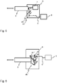
- Fig. 7 is a schematic view of a braking system according to a fourth exemplary embodiment.
- the fourth embodiment differs from the third embodiment in the configuration of the lever mechanism and the respective actuation of the transfer element 5.
- the lever mechanism 4b''' of the secondary brake actuator 4''' comprises a toggle lever 41''' with a respective pivot 42"'.
- the one end of the toggle lever 41''' is connected to the transfer element 5 and the other end of the toggle lever 41''' rests against a stop 45.
- An actuation of the lever mechanism 4b''' is indicated by the bidirectional arrow. If the toggle lever 41''' is expanded, i.e.
- the transfer element 5 is moved and/or held in the at least one braking position.
- the at least one braking position of the transfer element 5 corresponds to a state of the toggle lever 41''' before reaching its dead center. Therefore, the lever mechanism 4b''' is capable of readjusting the at least one braking position in the event of cooled down brakes or wear.
- Fig. 8 is a schematic view of a braking system according to a fifth exemplary embodiment.
- the braking system comprises two transfer elements 5 to apply a braking force on a brake 2, in particular a brake pad.
- the braking system comprises only one or more than two transfer elements 5.
- Each of the transfer elements 5 comprises a braking member 5a to directly act on the brake 2.
- the transfer elements 5 may indirectly act on the brake 2 by applying a respective force to intermediate members operatively arranged between the respective transfer element 5 and the brake 2.
- the secondary brake actuator according to the fifth embodiment comprises a friction member 4c configured to engage a radial surface of the transfer element 5 to hold the transfer element in the at least one braking position.
- the friction members 4c are movable perpendicular to the moving direction of the transfer element 5 between an engagement position to apply a holding force and a non-engagement position to allow a movement of the transfer element 5 as indicated by the vertical bidirectional arrow.
- the friction member 4c is biased to allow a readjustment of a respective engagement position to compensate for tolerances or wear.
- the readjustment may be provided by other elements of the secondary brake actuator or by the secondary brake actuating device.
- the transfer element 5 is moved in the at least one braking position by the main brake actuator 7, as indicated by the horizontal bidirectional arrow, to be held by the friction member 4c when actuated by the secondary brake actuator accordingly.
- the main brake actuator 7 of the fifth embodiment is configured to move the transfer element 5 in the at least one braking position during a driving operation as well as a non-driving operation.
- the actuation of the friction member 4c is configured to provide a sufficient holding force to hold the transfer element in the at least one braking position even after deactivation of the main brake actuator 7.
- the main brake actuator may be further activated.
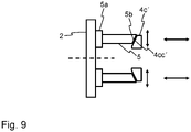
- Fig. 9 is a schematic view of a braking system according to a sixth exemplary embodiment.
- the sixth embodiment differs from the fifth embodiment in the configuration of the friction member and the respective holding characteristic of the transfer element 5.
- the braking system comprises two transfer elements 5 to apply a braking force on the brake 2.
- the secondary brake actuator comprises a friction member 4c' configured to hold the transfer element 5 in the at least one braking position when respectively actuated.
- the friction member 4c' comprises a wedge surface 4cc' facing an end face of the transfer element 5 opposite to the braking member 5a.
- the end face of the transfer element 5 is inclined with respect to a plane perpendicular to the moving direction of the transfer element 5, indicated by the horizontal bidirectional arrow.
- the inclination of the end face of the transfer element 5 corresponds to the inclination of the wedge surface 4cc' to provide a contact area between the end face of the transfer element and the wedge surface 4cc' when the wedge surface 4cc' is moved against the inclined end face of the transfer element 5, as indicated by the vertical bidirectional arrow.
- Due to the wedge surface 4cc' the friction member 4c' is capable of readjusting the at least one braking position in the event of a cooling down of the brake 2 or wear.
- the friction member 4c' is therefore biased to stay in contact with the inclined end face of the transfer element 5 when holding the transfer element 5 in the at least one braking position.
Landscapes
- Engineering & Computer Science (AREA)
- General Engineering & Computer Science (AREA)
- Mechanical Engineering (AREA)
- Transportation (AREA)
- Physics & Mathematics (AREA)
- Electromagnetism (AREA)
- Braking Arrangements (AREA)
Priority Applications (2)
| Application Number | Priority Date | Filing Date | Title |
|---|---|---|---|
| EP21170263.4A EP4080080A1 (fr) | 2021-04-23 | 2021-04-23 | Système de freinage pour un véhicule utilitaire, procédé d'application d'une force de freinage et véhicule utilitaire |
| PCT/EP2022/058168 WO2022223247A1 (fr) | 2021-04-23 | 2022-03-28 | Système de freinage pour véhicule utilitaire, procédé d'application d'une force de freinage et véhicule utilitaire |
Applications Claiming Priority (1)
| Application Number | Priority Date | Filing Date | Title |
|---|---|---|---|
| EP21170263.4A EP4080080A1 (fr) | 2021-04-23 | 2021-04-23 | Système de freinage pour un véhicule utilitaire, procédé d'application d'une force de freinage et véhicule utilitaire |
Publications (1)
| Publication Number | Publication Date |
|---|---|
| EP4080080A1 true EP4080080A1 (fr) | 2022-10-26 |
Family
ID=75746130
Family Applications (1)
| Application Number | Title | Priority Date | Filing Date |
|---|---|---|---|
| EP21170263.4A Pending EP4080080A1 (fr) | 2021-04-23 | 2021-04-23 | Système de freinage pour un véhicule utilitaire, procédé d'application d'une force de freinage et véhicule utilitaire |
Country Status (2)
| Country | Link |
|---|---|
| EP (1) | EP4080080A1 (fr) |
| WO (1) | WO2022223247A1 (fr) |
Citations (6)
| Publication number | Priority date | Publication date | Assignee | Title |
|---|---|---|---|---|
| US3393774A (en) * | 1967-01-03 | 1968-07-23 | Neway Equipment Co | Brake actuating system |
| DE69807997T2 (de) * | 1997-07-18 | 2003-08-07 | Renault Vehicules Industriels, Saint Priest | Kraftfahrzeugbremsvorrichtung mit Feststellbremse |
| EP1529706A1 (fr) * | 2003-11-04 | 2005-05-11 | ArvinMeritor Technology, LLC | Frein de stationnement pneumatique |
| US20080036289A1 (en) * | 2006-05-03 | 2008-02-14 | Thompson Richard E | Vehicle braking systems |
| DE102013110951A1 (de) * | 2013-10-02 | 2015-04-02 | Linde Material Handling Gmbh | Mobile Arbeitsmaschine mit Zweikreisbremse |
| DE102017123266A1 (de) * | 2017-10-06 | 2019-04-11 | Thyssenkrupp Ag | Mechanische Bremsvorrichtung |
-
2021
- 2021-04-23 EP EP21170263.4A patent/EP4080080A1/fr active Pending
-
2022
- 2022-03-28 WO PCT/EP2022/058168 patent/WO2022223247A1/fr active Application Filing
Patent Citations (6)
| Publication number | Priority date | Publication date | Assignee | Title |
|---|---|---|---|---|
| US3393774A (en) * | 1967-01-03 | 1968-07-23 | Neway Equipment Co | Brake actuating system |
| DE69807997T2 (de) * | 1997-07-18 | 2003-08-07 | Renault Vehicules Industriels, Saint Priest | Kraftfahrzeugbremsvorrichtung mit Feststellbremse |
| EP1529706A1 (fr) * | 2003-11-04 | 2005-05-11 | ArvinMeritor Technology, LLC | Frein de stationnement pneumatique |
| US20080036289A1 (en) * | 2006-05-03 | 2008-02-14 | Thompson Richard E | Vehicle braking systems |
| DE102013110951A1 (de) * | 2013-10-02 | 2015-04-02 | Linde Material Handling Gmbh | Mobile Arbeitsmaschine mit Zweikreisbremse |
| DE102017123266A1 (de) * | 2017-10-06 | 2019-04-11 | Thyssenkrupp Ag | Mechanische Bremsvorrichtung |
Also Published As
| Publication number | Publication date |
|---|---|
| WO2022223247A1 (fr) | 2022-10-27 |
Similar Documents
| Publication | Publication Date | Title |
|---|---|---|
| JP5054273B2 (ja) | 車輪ブレーキ装置 | |
| JPH0462904B2 (fr) | ||
| JP2000213574A (ja) | 車両のパ―キングブレ―キ装置 | |
| MX2014003700A (es) | Dispositivo de freno con actuacion electromecanica. | |
| EP3271225B1 (fr) | Arrangement de frein de stationnement | |
| JP2000145844A (ja) | 車輪ブレ―キ装置 | |
| CA2122883C (fr) | Dispositif de freinage monte sur camion | |
| EP4080080A1 (fr) | Système de freinage pour un véhicule utilitaire, procédé d'application d'une force de freinage et véhicule utilitaire | |
| CA2442787C (fr) | Dispositif ameliore de jonction de levier de frein a main pour frein de vehicule ferroviaire monte sur bogie monocylindre | |
| JP2002517677A (ja) | 乗物用ブレーキのためのアクチュエータサブアセンブリ及びこの型式のアクチュエータサブアセンブリを備える乗物用ブレーキ | |
| JP2002509835A (ja) | ペダル機構 | |
| KR20220118318A (ko) | 차량용 마찰 브레이크 시스템 | |
| CN211202695U (zh) | 电子机械制动装置和具有其的车辆 | |
| EP4080081A1 (fr) | Système de freinage pour un véhicule utilitaire et véhicule utilitaire comprenant un tel système de freinage | |
| JP7461383B2 (ja) | 低剛性の弾性リザーブを有するアクチュエータを備えた電気機械式ドラムブレーキ | |
| US20220055597A1 (en) | Brake cylinder comprimising a locking device for mechanical brake force locking | |
| CN114616148B (zh) | 电动停车制动器 | |
| CN112714728A (zh) | 用于确定机电式的制动器的设计参数的方法以及机电式的制动器 | |
| US4265492A (en) | Braking apparatus for vehicles | |
| EP0952059A1 (fr) | Mécanisme de frein parking pour frein à inertie pour une remorque | |
| CN220910306U (zh) | 制动调节机构、制动夹钳及车辆 | |
| JPH04259018A (ja) | クラッチ作動機構 | |
| US11897731B2 (en) | Brake device, e.g. with an eccentric element, for braking a traveling body that can be moved in a guided manner along a guide rail in a movement direction | |
| EP4186756A1 (fr) | Actionneur de frein électromécanique et actionneur de verrouillage correspondant | |
| EP4163169A1 (fr) | Actionneur de frein et dispositif d'actionnement de frein |
Legal Events
| Date | Code | Title | Description |
|---|---|---|---|
| PUAI | Public reference made under article 153(3) epc to a published international application that has entered the european phase |
Free format text: ORIGINAL CODE: 0009012 |
|
| STAA | Information on the status of an ep patent application or granted ep patent |
Free format text: STATUS: THE APPLICATION HAS BEEN PUBLISHED |
|
| AK | Designated contracting states |
Kind code of ref document: A1 Designated state(s): AL AT BE BG CH CY CZ DE DK EE ES FI FR GB GR HR HU IE IS IT LI LT LU LV MC MK MT NL NO PL PT RO RS SE SI SK SM TR |
|
| STAA | Information on the status of an ep patent application or granted ep patent |
Free format text: STATUS: REQUEST FOR EXAMINATION WAS MADE |
|
| 17P | Request for examination filed |
Effective date: 20230426 |
|
| RBV | Designated contracting states (corrected) |
Designated state(s): AL AT BE BG CH CY CZ DE DK EE ES FI FR GB GR HR HU IE IS IT LI LT LU LV MC MK MT NL NO PL PT RO RS SE SI SK SM TR |
|
| RAP3 | Party data changed (applicant data changed or rights of an application transferred) |
Owner name: KNORR-BREMSE SYSTEME FUER NUTZFAHRZEUGE GMBH |
|
| REG | Reference to a national code |
Ref country code: DE Ref legal event code: R079 Free format text: PREVIOUS MAIN CLASS: F16D0065140000 Ipc: B60T0013220000 |
|
| GRAP | Despatch of communication of intention to grant a patent |
Free format text: ORIGINAL CODE: EPIDOSNIGR1 |
|
| STAA | Information on the status of an ep patent application or granted ep patent |
Free format text: STATUS: GRANT OF PATENT IS INTENDED |
|
| RIC1 | Information provided on ipc code assigned before grant |
Ipc: F16D 127/06 20120101ALN20240708BHEP Ipc: F16D 125/68 20120101ALN20240708BHEP Ipc: F16D 125/66 20120101ALN20240708BHEP Ipc: F16D 125/64 20120101ALN20240708BHEP Ipc: F16D 125/60 20120101ALN20240708BHEP Ipc: F16D 65/62 20060101ALI20240708BHEP Ipc: F16D 65/28 20060101ALI20240708BHEP Ipc: F16D 65/22 20060101ALI20240708BHEP Ipc: F16D 65/18 20060101ALI20240708BHEP Ipc: F16D 59/02 20060101ALI20240708BHEP Ipc: B60T 13/26 20060101ALI20240708BHEP Ipc: B60T 13/22 20060101AFI20240708BHEP |
|
| INTG | Intention to grant announced |
Effective date: 20240802 |