EP4078006B1 - Rohrisoliervorrichtung mit dichtung - Google Patents
Rohrisoliervorrichtung mit dichtung Download PDFInfo
- Publication number
- EP4078006B1 EP4078006B1 EP20902764.8A EP20902764A EP4078006B1 EP 4078006 B1 EP4078006 B1 EP 4078006B1 EP 20902764 A EP20902764 A EP 20902764A EP 4078006 B1 EP4078006 B1 EP 4078006B1
- Authority
- EP
- European Patent Office
- Prior art keywords
- sealing head
- pipe
- sealing
- head
- isolation device
- Prior art date
- Legal status (The legal status is an assumption and is not a legal conclusion. Google has not performed a legal analysis and makes no representation as to the accuracy of the status listed.)
- Active
Links
Images













Classifications
-
- F—MECHANICAL ENGINEERING; LIGHTING; HEATING; WEAPONS; BLASTING
- F16—ENGINEERING ELEMENTS AND UNITS; GENERAL MEASURES FOR PRODUCING AND MAINTAINING EFFECTIVE FUNCTIONING OF MACHINES OR INSTALLATIONS; THERMAL INSULATION IN GENERAL
- F16L—PIPES; JOINTS OR FITTINGS FOR PIPES; SUPPORTS FOR PIPES, CABLES OR PROTECTIVE TUBING; MEANS FOR THERMAL INSULATION IN GENERAL
- F16L55/00—Devices or appurtenances for use in, or in connection with, pipes or pipe systems
- F16L55/10—Means for stopping flow in pipes or hoses
- F16L55/105—Closing devices introduced radially into the pipe or hose
-
- F—MECHANICAL ENGINEERING; LIGHTING; HEATING; WEAPONS; BLASTING
- F16—ENGINEERING ELEMENTS AND UNITS; GENERAL MEASURES FOR PRODUCING AND MAINTAINING EFFECTIVE FUNCTIONING OF MACHINES OR INSTALLATIONS; THERMAL INSULATION IN GENERAL
- F16L—PIPES; JOINTS OR FITTINGS FOR PIPES; SUPPORTS FOR PIPES, CABLES OR PROTECTIVE TUBING; MEANS FOR THERMAL INSULATION IN GENERAL
- F16L41/00—Branching pipes; Joining pipes to walls
- F16L41/04—Tapping pipe walls, i.e. making connections through the walls of pipes while they are carrying fluids; Fittings therefor
- F16L41/06—Tapping pipe walls, i.e. making connections through the walls of pipes while they are carrying fluids; Fittings therefor making use of attaching means embracing the pipe
Definitions
- the disclosure describes a pipe isolation device for use in pipes.
- the pipe isolation device may be used in pipelines carrying fluids such as pressurized fluids, high or low temperature fluids, steam, or hazardous fluids.
- double isolation-and-bleed When performing pipeline maintenance or servicing, such as during hot tapping procedures, it is necessary to provide isolation of a "live" section of pipe.
- a double isolation-and-bleed apparatus also referred to as a double block-and-bleed apparatus.
- double isolation-and-bleed refers to the setting of two seals in a pipe with a bleed port located therebetween. If fluid leaks past the first seal, it is contained by the second seal and forced to exit the pipe through the bleed port.
- the double isolation-and-bleed pipe isolation devices known in the industry generally comprise a series of pivoting arms. Due to the challenging environment, the pivoting arms represent points of potential failure.
- US 7 841 364 B2 discloses a pipe isolation device with a control bar head, first and second sealing heads each provided with a sealing element and arranged to gain access to an interior space of a pipe with a center axis defining an axial direction.
- a pipe isolating device according to claim 1 and a method of isolating a pipe according to claim 11 are provided.
- connection As used herein, the terms “connect”, “connection”, “connected”, “in connection with”, and “connecting” are used to mean “in direct connection with” or “in connection with via one or more elements”; and the term “set” is used to mean “one element” or “more than one element”. Further, the terms “couple”, “coupling”, “coupled”, “coupled together”, and “coupled with” are used to mean “directly coupled together” or “coupled together via one or more elements”. As used herein, the terms “up” and “down”; “upper” and “lower”; “top” and “bottom”; and other like terms indicating relative positions to a given point or element are utilized to more clearly describe some elements.
- the present disclosure generally relates to achieving at least one seal in a pipe.
- Embodiments may have multiple seals in a pipe with a depressurized zone between the seals. This increases the safety of plugging a pipe by having a back-up seal and allows for any leakage past the primary seal to be vented out the bleed port.
- Some embodiments of the pipe isolation device of the present disclosure achieve the multiple seals through one branch opening in the pipe so that it reduces the amount of equipment involved in safely sealing or isolating the pipe.
- Embodiments of the pipe isolation device of the present disclosure may be a tool that has a first sealing head and a second sealing head and provides a means to achieve two (or more) seals inside a pipe between the sealing heads.
- the pressure in the space between the two seals can be bled so that one seal is a primary seal and the other is a secondary backup seal.
- the tool is set by traveling through a tapped hole forming a lateral access opening inside a fitting branch on the pipe and product flow can continue through this fitting if a bypass line is set up.
- the pipe isolation device is configured to traverse at an angle, e.g. a right angle, as the pipe isolation device moves through the lateral access opening.
- Pipe isolation device 100 further includes a first sliding engagement 108 for providing a slidable engagement connection between the control bar head 102 and the first sealing head 104, and a second sliding engagement 109 for providing a slidable engagement connection between the first sealing head 104 and the second sealing head 106, see Figure 1 and Figure 4 .
- First sliding engagement 108 may be formed by a pair of first guide tracks 110, see Figure 1 and Figure 4 , attached to a side of the control bar head 102 and the first guide members 112, see Figure 4 , attached to a first side of the first sealing head 104.
- Each of the first guide members 112 is interconnected with one of the first guide tracks 110, as shown in Figure 4 , to provide for sliding engagement between the control bar head 102 and the first sealing head 104.
- First guide tracks 110 extend along a control bar surface 117. Control bar surface 117 is at an acute angle with respect to a vertical axis 129 extending through a center of the control bar head 102.
- the first sliding engagement 108 may be formed by one first guide track 110 and one first guide member 112 interconnected with one another to form a sliding engagement.
- more than two first guide tracks 110 and first guide members 112 may be used to form the first sliding engagement 108 interconnecting the control bar head 102 and the first sealing head 104.
- one or more first guide tracks 110 may be attached to the first sealing head 104, and one or more first guide members 112 may be attached to the control bar head 102 to form the first sliding engagement 108 between the control bar head 102 and the first sealing head 104.
- Second sliding engagement 109 may be formed by a pair of second guide tracks 114 and second guide members 116, see Figure 1 and Figure 4 .
- Second guide tracks 114 are attached to a second side of the first sealing head 104 and second guide members 116 are attached to an opposing first side of the second sealing head 106.
- Each of the second guide members 116 is interconnected with one of the second guide tracks 114, see Figure 4 and Figure 9 , to provide for sliding engagement between the first sealing head 104 and the second sealing head 106.
- Second guide tracks 114 extend along an outer surface 118 of the first sealing head 104
- second guide members 116 extend along an inner surface of the second sealing head 106 that opposes the outer surface 118 of the first sealing head 104.
- Outer surface 118 is at an acute angle with respect to the vertical axis 129.
- the second sliding engagement 109 may be formed by one second guide track 114 and one second guide member 116 interconnected with one another. In another embodiment, more than two second guide tracks 114 and second guide members 116 may be used to form the second sliding engagement 109 interconnecting the sealing heads 104, 106. In another embodiment, one or more second guide tracks 110 may be attached to the second sealing head 106 and one or more second guide members 116 may be attached to the first sealing head 104 to form the second sliding engagement 109 between the sealing heads 104, 106.
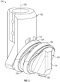
- First sealing head 104 has a first seal element 120 and the second sealing head 106 has a second seal element 122, see Figures 1-2 .
- First seal element 120 extends around a main body of the first sealing head 104 and the second seal element 122 extends around a main body of the second sealing head 106 to form circumferential seal elements.
- Seal elements 120, 122 may be made from elastomeric materials.
- First seal element 120 is disposed along a first outer perimeter of the first sealing head 104 to form the first circumferential seal element.
- Second seal element 122 is disposed along a second outer perimeter of the second sealing head 106 to form the second circumferential seal element.
- a first nose ring 124 may be positioned adjacent to the first seal element 120, and a second nose ring 126 may be positioned adjacent to the second seal element 122.
- a first retaining ring 127 may be positioned adjacent to the first seal element 120, and a second retaining ring 128 may be positioned adjacent to the second seal element 122, see Figure 4 .
- first seal element 120 is disposed between the first nose ring 124 and the first retaining ring 127
- second seal element 122 is disposed between the second nose ring 126 and the second retaining ring 128.
- Nose rings 124, 126 and retaining rings 127, 128 provide support to the seal elements 120, 122 and prevent the seal elements 120, 122 from extruding when under pressure.
- Second sealing head 106 may have an outer surface 130 with a nose element 134 extending outwardly therefrom.
- One or more pads 136 may be attached to the sealing heads 104, 106.
- Pads 136 may be made of brass, iron, polymer or other material that allows for sliding of the sealing heads 104, 106.
- a pad 136 is attached to a bottom section of the nose element 134. Sliding engagements 108, 109 are configured so that the pad 136 slide along a pipe ID as the pipe isolation device 100 is translated through the fitting branch of the pipe from the fully retracted position, shown in Figure 1 , to the fully set position, shown in Figure 2 .
- Pads 136 may be referred to as a skid element or nose pad.
- Pad 136 positions the sealing heads 104, 106 linearly along an axis of the pipe and slides along the bottom of the pipe as the pipe isolation device 100 moves to the fully set position.
- the axis of the pipe is transverse, e.g. perpendicular, to the vertical axis 129.
- the sealing heads 104, 106 move outwardly away from the vertical axis 129 that extends through the control bar head 102.
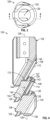
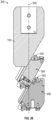
- FIG. 3 a top view of an embodiment of the pipe isolation device 100 in a fully retracted position is shown.
- Figure 4 shows a cross-section at section lines 4-4 of the pipe isolation device 100 shown in Figure 3 .
- sealing heads 104, 106 are oriented in-line with the control bar head 102 when in the fully retracted position.
- Vertical axis 129 extends through the sealing heads 104, 106 and through the center of the control bar head 102 and illustrates that the sealing heads 104, 106 and the control bar head 102 are oriented in-line with one another when in the fully retracted position.
- first guide tracks 110 is shown with one of the first guide members 112 interlocked in the first guide track 110
- second guide tracks 114 is shown with one of the second guide members 116 interlocked in the second guide track 114.
- Each first guide track 110 includes a first track slot 140 that is elongated and formed by interior walls of the elongated, first guide track 110.
- First track slots 140 may have a dovetail shape, T-shape, C-shape, or other shape where the first guide members 112 have a corresponding dovetail shape, T-shape, C-shape, or other shape corresponding to the track slots 140 and the first guide members 112 are retained in the first track slots 140.
- First guide tracks 110 and the first guide members 112 define a first fixed path for the first sealing head 104.
- First sliding engagement 108 is configured to permit the first sealing head 104 to move along the first fixed path between the first retracted position and the first set position.
- First sealing head 104 moves along the first fixed path with each of the first guide members 112 engaged with one of the first guide tracks 110 and moving in the first track slots 140 so that the first sealing head 104 moves from a first retracted position, shown in Figure 1 , to a first set position, shown in Figure 2 .
- First guide tracks 110 are oriented at an acute angle with respect to the vertical axis 129 of the control bar head 102, and the first sealing head 104 moves outwardly with respect to the vertical axis 129 as the first sealing head 104 moves from the first retracted position, shown in Figure 1 , to the first set position, shown in Figure 2 .
- This outward movement of the first sealing head 104 with respect to the vertical axis 129 as the first sealing head 104 moves from the first retracted position to the first set position allows the first sealing head 104 to traverse the right angle between a pipe inlet and a pipe.
- Each second guide track 114 includes a second track slot 142 that is elongated and formed by interior walls of the elongated, second guide track 114.
- Second track slots 142 may have a dovetail shape, T-shape, C-shape, or other shape.
- Second guide members 116 have a corresponding dovetail shape, T-shape, C-shape, or other shape corresponding to track slots 140 and are retained in the second track slots 142.
- guide members 112, 116 may include at least one load bearing roller engageable within guide tracks 110, 114 to form the sliding engagements 108, 109.
- Second guide tracks 114 and second guide members 116 define a second fixed path for the second sealing head 106.
- Second sliding engagement 109 is configured to permit the second sealing head 106 to move along the second fixed path between the second retracted position and the second set position.
- Second sealing head 106 moves along the second fixed path with each of the second guide member 116 engaged with one of the second guide tracks 114 and moving in the second track slot 142 so that the second sealing head 106 moves from the second retracted position, shown in Figure 1 , to the second set position, shown in Figure 2 .
- Second guide tracks 114 are oriented at an acute angle with respect to the vertical axis 129 of the control bar head 102 and the second sealing head 106 moves outwardly from the vertical axis 129 as the second sealing head 106 moves from the fully retracted position, shown in Figure 1 , to the fully set position, shown in Figure 2 .
- This outward movement of the second sealing head 106 with respect to the vertical axis 129 as the second sealing head 106 moves from the second retracted position to the second set position allows the second sealing head 106 to traverse the right angle between a pipe inlet and a pipe.
- First guide tracks 110 and the second guide tracks 114 are parallel in the embodiment shown in Figure 4 .
- Guide tracks 110, 114 each include a first track stop 144, that prevents the sealing heads 104, 106 from traveling downwards in the guide tracks 110, 114 when the pipe isolation device 110 is in the fully retracted position, shown in Figure 4 .
- First track stops 144 block sealing heads 104, 106 from moving downwards in the guide tracks 110, 114 and falling off a bottom end of the guide tracks 110, 114.
- one of the first track stops 144 is located at a bottom section of each of the guide tracks 110, 114 to position the sealing heads 104, 106 in the fully retracted position.
- Guide tracks 110, 114 may each include a second track stop 146, as shown in Figure 1 , disposed at a top section of the guide tracks 110, 114.
- Second track stops 146 may be in the form of a stop block, as shown in Figure 1 .
- Second track stops 146 block sealing heads 104, 106 from moving upwards in the guide tracks 110, 114.
- Track stops 144, 146 retain the sealing heads 104, 106 within a selected section of the guide tracks 110, 114.
- Track stops 146 position the sealing heads 104, 106 in line with one another in the fully set position and prevent the sealing heads 104, 106 from travelling beyond and falling off a top end of the guide tracks 110, 114.
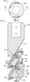
- FIG. 5 shows a top view of an embodiment of the pipe isolation device 100 in a fully retracted position.
- Figure 6 shows a cross-section at section lines 6-6 of the pipe isolation device 100 shown in Figure 5 .
- a locking mechanism including a first locking mechanism 150 for temporarily locking the first sealing head 104 in the first retracted position and a second locking mechanism 152 for temporarily locking the second sealing head 106 in the second retracted position.
- the locking mechanisms 150, 152 lock the sealing heads 104, 106 in the fully retracted position with the locking mechanisms 150, 152 in a locked state as the sealing heads 104, 106 travel through a lateral access opening of a pipe.
- the locking mechanisms 150, 152 release from the locked state to an unlocked state in response to an applied force as the control bar head 102 is conveyed through the lateral access opening.
- the locking mechanisms 150, 152 in the unlocked state permit the first sliding head 104 and the second sliding head 106 to move to the fully set position.
- the overall locking mechanism may be configured to lock at least one of the sealing heads 104, 106 in the fully retracted position and to unlock at least one of the sealing heads 104, 106 in response to an applied force.
- the first locking mechanism 150 may be formed by a first push rod 154 attached to the first sealing head 104, a first pocket 156 in the first sealing head 104, and a first latch 158 disposed in the first pocket 156.
- first latch 158 is biased to engage with the first track stop 144 on the first guide track 110.
- the engagement between the first latch 158 and the first track stop 144 secures the first sealing head 104 in the first retracted position, as shown in Figure 6 , to place the first sealing head 104 in a first locked state.
- the engagement between the first latch 158 and the first track stop 144 may be a frictional engagement that secures the first sealing head 104 in the first locked state.
- the engagement between the first latch 158 and the first track stop 144 may be an abutment engagement that secures the first sealing head 104 in the first locked state.
- the first locked state temporarily locks the first sealing head 104 in the first retracted position.
- the first push rod 154 may be actuated when the first push rod 154 engages and is displaced by a bottom of a pipe as the pipe isolation device 100 moves from the fully retracted position to the fully set position.
- First locking mechanism 150 changes or releases to the first unlocked state in response to the second applied force meeting a second force threshold.
- the first locking mechanism 150 is placed into the first unlocked state when the first latch 158 is pushed into the first pocket 156 so that the first latch 158 is disengaged with the first track stop 144.
- the disengagement between the first latch 158 and the first track stop 144 places the first sealing head 104 in the first unlocked state so that the first sealing head 104 is permitted to move from the first retracted position to the first set position.
- Second push rod 162 may be moved upwards in the second sealing head 106 by applying a first applied force against a bottom end of second push rod 162 to force a top end of the second push rod 162 against a top end of second latch 166. Second push rod 162 moves forward with enough force to overcome the bias of the second latch 166 and to depress the second latch 166 into the second pocket 164.
- the bias of the second latch 166 may be provided by a second spring 176 attached to the second latch 166 or another biasing member that biases the second latch 166 out of the second pocket 164.
- Springs 174, 176 may be compression springs.
- the second push rod 162 may be actuated when the second push rod 162 engages and is displaced by a bottom of a pipe as the pipe isolation device 100 moves from the fully retracted position to the fully set position.
- Second locking mechanism 152 changes or releases to the second unlocked state in response to the first applied force being applied meeting a first force threshold.
- Second locking mechanism 152 is placed into the second unlocked state when the second latch 166 is pushed into the second pocket 164 so that the second latch stop 168 does not block the second latch 166 and the second sealing head 106 is permitted to move from the second retracted position to the second set position.
- FIG. 9 a partial, quarter-sectional view of the pipe isolation device 100 in the fully set position is shown to further illustrate how sliding engagements 108, 109 provide sliding connections between the control bar head 102 and the first sealing head 104 and between the first sealing head 104 and the second sealing head 106.
- One of the first guide tracks 110 and one of the first guide members 112 of the first sliding engagement 108 are shown interlocked and slidably connected.
- one of the second guide tracks 114 and one of the second guide members 116 are shown interlocked and slidably connected.
- Guide tracks 110, 114 have elongated first track slots 140 and second guide tracks 142, as shown in Figure 4 , that are dovetail-shaped, as illustrated in Figure 9 .
- Guide members 112, 116 are dovetail-shaped to correspond with their respective guide tracks 110, 114.
- FIG. 12 shows a top view of the pipe isolation device 100 in the fully set position
- Figure 13 shows a side view of the pipe isolation device 100 in the fully retracted position
- Figure 14 shows a cross-sectional view of the pipe isolation device 100 in the fully set position along section line 14-14 of Figure 12 .
- pads 136 are attached to a top section and a bottom section of sealing heads 104,106 to slide along internal surface of a pipe and center the sealing heads 104, 106 in the pipe as the pipe isolation device 100 moves to the fully set position.
- Second pin 172 is formed by a shear pin and is shown in Figure 14 after the second pin 172 has been sheared.
- First pin 170 is formed by a shear pin and is shown in Figure 14 after the first pin has been sheared. Operation of pins 170, 172 shown in Figure 14 is described in more detail with respect to Figures 18-23 .
- Pipe isolation device 100 has a retracted length L R in the fully retracted position, as shown in Figure 13 .
- first sealing head 104 and second sealing head 106 are aligned with one another to form a cylindrical shape and have a perpendicular orientation with respect to the control bar head 102, as illustrated by a horizontal axis 180 extending through control bar head 102 and sealing heads 104, 106.
- Horizontal axis 180 extends through a center of the sealing heads 104, 106 and is perpendicular to vertical axis 129 extending through the center of the control bar head 102.
- Horizontal axis 180 may align with the center axis of a pipe when the pipe isolation device 100 is deployed in the fully set position in the pipe.
- First sliding engagement 108 is configured so that the first sealing head 104 moves along the first fixed path, as depicted by first track axis 182, and the second sliding engagement 109 is configured so that the second sealing head 106 moves along the second fixed path, as depicted by second track axis 184, as the pipe isolation device 100 moves from the fully retracted position to the fully set position.
- the fixed paths of sliding engagements 108 may be formed by guide tracks 110, 114.
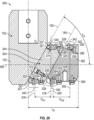
- the fixed paths formed by the guide tracks 110, 114 are at an acute angle, referred to as the track angle T A , with respect to the horizontal axis 180 extending through the center of the sealing heads 104, 106, as shown by track angle T A .
- track angle T A may be from 46 degrees to 70 degrees from the horizontal axis 180, as described below: 46 ° ⁇ T A ⁇ 70 °
- Pipe isolation device 100 in the fully set position has a deployed length L D and a deployed height H D , as shown in Figure 14 .
- Deployed length L D is measured from the vertical axis 129 extending through the center of the control bar 102 to the end of the second sealing head 106.
- Deployed height H D is measured from the top to the bottom of the sealing heads 104, 106.
- the deployed height H D may be measured at an outermost surface of the pads 136 on the bottom and top sections of the sealing heads 104, 106.
- the deployed height H D of the sealing heads 104, 106 is approximately the interior diameter (ID) of the pipe that the pipe isolation device 100 may be deployed. Sliding engagements 108, 109 provide a compact deployed length L D for the pipe isolation device 100.
- the compact deployed length L D helps the pipe isolation device 100 stay within the bounds of a fitting sleeve (not shown) that may be formed around a lateral access opening through which the pipe isolation device 100 is inserted when in the fully set position. Limiting the deployed length L D and staying within the bounds of a fitting sleeve helps prevent damage to the pipe due to the reaction loads of the pipe isolation device 100 against the pipe when the pipe is pressurized.
- Pipe isolation device 100 is configured for a pipe having a lateral access opening that has a diameter size approximately equal to the internal diameter (ID) of the pipe being sealed, sometimes referred to as a size-on-size tap.
- ID internal diameter
- the length of a typical fitting sleeve FS L on a pipe for a full-encirclement pipe fitting is approximately the length of the internal diameter of the pipe from the center axis of the pipe branch to one of the first sleeve ends.
- the deployed length L D of the pipe isolation device 100 may be limited with respect to the deployed height H D of the sealing heads 104, 106 to facilitate operation.
- the deployed length L D of the pipe isolation device 100 also may be limited with respect to the retracted length L R of the pipe isolation device 100.
- the ratio of deployed length L D of the pipe isolation device 100 and deployed height H D of the sealing heads 104, 106 is in the following range: 0.56 ⁇ L D H D ⁇ 1.60
- the size of a pipe isolation device 100 may be selected to correspond to the internal diameter of the selected pipe that will be sealed, and accordingly, different pipe isolation devices 100 may have different deployed lengths L D , retracted lengths L R , and deployed heights H D depending on the internal diameter of the selected pipe to be sealed.
- the ratio of the retracted length L R of the pipe isolation device 100 and the internal diameter, referred to as ID P , of the selected pipe to be sealed is in the following range: 2.25 ⁇ L R ID P ⁇ 4.00
- the deployed height H D of the pipe isolation device 100 to be used in the selected pipe may be equal to the internal diameter ID P of the selected pipe.
- An overall compact size of the pipe isolation device 100 may be beneficial.
- the compact size may help with installation of the pipe isolation device 100 when there is limited space for installation at the location of the lateral access opening.
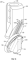
- Pipe isolation device 200 includes the control bar head 102 and a single sealing head 204 slidably connected to the control bar head 102.
- Embodiments of pipe isolation device 200 are like pipe isolation device 100 but the pipe isolation device 200 has only one sealing head, referred to as the single sealing head 204.
- the single sealing head 204 may be like the second sealing head 106 of the pipe isolation device 100 with the single sealing head 204 slidably connected to the control bar head 102.
- the single sealing head 204 may be like the first sealing head 104 of the pipe isolation device 100 without the second sealing head 106.
- Pipe isolation device 200 is in the fully retracted position when the first sealing head 204 is in the first retracted position and is in the fully set position when the first sealing head 204 is in the first set position.
- Pipe isolation device 200 includes the first sliding engagement 108 for providing a slidable engagement connection between the control bar head 102 and the single sealing head 204, see Figure 15 .
- First sliding engagement 108 of the pipe isolation device 200 is configured to permit the single sealing head 204 to move along the first fixed path between the first retracted position and the first set position.
- First sliding engagement 108 for pipe isolation device 200 is configured as described and illustrated in Figure 1 and Figure 4 with respect to the pipe isolation device 100.
- first sliding engagement 108 may be formed by a pair of first guide tracks 110, see Figure 15 , attached to a side of the control bar head 102 and the first guide members 112, see Figure 17 , attached to a first side of the single sealing head 204.
- Each of the first guide members 112 is interconnected with one of the first guide tracks 110, as shown in Figure 4 , to provide for sliding engagement between the control bar head 102 and the single sealing head 204.
- First guide tracks 110 extend along the control bar surface 117.
- Control bar surface 117 is at an acute angle with respect to a vertical axis 129 extending through a center of the control bar head 102.
- Pipe isolation device 200 may include different embodiments of the first sliding engagement 108 as previously discussed with respect to the pipe isolation device 100.
- First seal element 120 is shown separated from the body of the single sealing head 204 to better illustrate the first seal element 104.
- the first seal element 120 extends around the outer perimeter of the body of the single sealing head 204 to form a circumferential seal for sealing a pipe.
- First seal element 120 is disposed between the first nose ring 124 and the first retaining ring 127.
- First nose ring 124 and first backing ring 127 provide support to the first seal element 120.
- First retaining ring 127 and first nose ring 124 attach to the body of the single sealing head 204 and may have a shape that corresponds to the first seal element 120.
- Single sealing head 204 may also be an embodiment of the second sealing head 106 of the pipe isolation device 100 shown in Figures 1 and 2 .
- Pipe isolation device 200 may include the first locking mechanism 150.
- First locking mechanism 150 is able to lock the single sealing head 204 in the first retracted position, as described previously with respect to the first sealing head 104 and as illustrated in Figure 6 and Figure 8 .
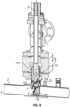
- the pipe isolation device 100 may be installed to double block the pipe 2, as shown in Figures 18-23 .
- Pipe isolation device 100 is installed in the pipe 2 through a lateral access opening 4 through a sequence of operations to position the pipe isolation device 100 from the fully retracted position through the lateral access opening 4 to the fully set position in the pipe 2.
- Pipe isolation device 100 may be used in a method to isolate or block fluid pressure in a pipe 2.
- Pipe isolation device 100 is configured to traverse at an angle, e.g.
- Sealing heads 104, 106 form a cylindrical shape fitting within the internal diameter of the pipe 2 when in the fully set position.
- Pipe isolation device 100 forms multiple seals in the pipe 2 in the fully set position.
- Pipe isolation device 100 is configured with the first sliding engagement 108 to permit the first sealing head 104 to slide relative to the control bar head 102 along a first fixed path and traverse a right angle to gain access to an interior space 6 of the pipe 2, and the second sliding engagement 109 permitting the second sliding head 106 to slide relative to the first sealing head 104 along the second fixed path and traverse the right angle to gain access to the interior space 6 of the pipe 2.
- the pipe isolation device 100 is in a fully retracted position and disposed in a pipe branch 17 above the access opening 4 and a bottom pipe section 5 in the pipe 2.
- An actuator 8 is attached to the control bar head 102 of the pipe isolation device 100.
- the actuator 8 moves the control bar head 102 downwards in the pipe branch 17 to convey the pipe isolation device 100 into the lateral access opening 4 during the installation of the pipe isolation device 100.
- Actuator 8 may include an actuator control bar 9 detachably connected to the control bar head 102.
- An arrow 11 is shown in Figure 18 to depict the downward movement of the actuator control bar 9 and connected pipe isolation device 100 through the pipe branch 17 and the access opening 4, and into the pipe 2.
- pipe branch 17 has a pipe fitting 10 with a pipe sleeve 12 that surrounds and extends outwardly from the access opening 4 to a first sleeve end 14 and a second sleeve end 16.
- Lateral access opening 4 may have a diameter equal to the internal diameter of the pipe 2, and the length from the vertical axis 129 through the center of the pipe branch 17 to each sleeve end 14, 16 may be equal to the internal diameter of the pipe 2, see Figure 23 .
- Pipe fitting 10 may be a full-encirclement pipe fitting that fits around the full circumference of the pipe 2.
- a first flange 20 connects the pipe fitting 10 and a valve 22.
- a second flange 24 connects the valve 22 and an isolation device housing 18.
- a third flange 26 connects to the isolation device housing and may be used for fluid flow from the pipe 2 that is temporarily blocked by the pipe isolation device 100.
- Bleed port 21 extends through the fitting sleeve 12 and the pipe 2 and is connected to a bleed joint 23.
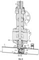
- Pipe isolation device 100 is in the fully retracted position at an initial stage of the installation with the sealing heads 104, 106 in locked states to temporarily lock the sealing heads 104, 106.
- first pin 170 and second pin 172 may be the locking mechanisms that lock the sealing heads 104, 106 in the locked states.
- Pins 170, 172 may be formed by shear pins that are un-sheared, as shown in Figure 18 and Figure 19 , and have not been activated to release the sealing heads 104, 106 to the unlocked states.
- FIG 20 when the second sealing head 106 engages the internal wall 3 of the pipe 2 the downward force on the control bar head 102 provided by actuator 8 results in a first applied force being applied to the second sealing head 106.
- Second pin 172 formed by a shear pin shears in response to the first applied force.
- Figure 19 shows a first portion of the second pin 172 in the first sealing head 104 and a second portion of the second pin 172 in the second sealing head 106 illustrating that the second pin 172 has sheared and the second sealing head 106 is in the unlocked state.
- the second locking mechanism that may be formed by second pin 172, has been released to release the second sealing head 106 from the second retracted position at the pipe bottom section 5.
- the second sealing head 106 When in the unlocked state, the second sealing head 106 is not biased in the second retracted position and is permitted to slide with respect to the first sealing head 104.
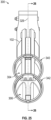
- Pipe isolation device 100 may be disposed within the bounds of the sleeve ends 14, 16 when positioned from the fully retracted position to the fully set position. As shown in Figure 23 , the sealing heads 104, 106 together have a cylindrical shape. Pipe isolation device 100, in some embodiments, is configured for a pipe having a lateral access opening 4 that has a diameter size approximately equal to the internal diameter of the pipe 2 being sealed, sometimes referred to as a size-on-size tap.
- a fitting sleeve length FS L may be measured from the vertical axis 129 extending through the center of the pipe branch 17 to the sleeve end, shown by sleeve vertical axis 40 in Figure 23 .
- the deployed length L D shown in Figure 14 , is less than the fitting sleeve length FS L .
- the deployed length L D may be greater than the FS L .
- Actuator 8 may move the control bar head 102 linearly downwards and along the vertical axis of the pipe branch 17 and through the pipe branch 17.
- the pipe isolation device 200 is conveyed through the lateral access opening 4 where the single sealing head 104 engages the internal wall 3 at the pipe bottom section 5 of the pipe 2.
- Pipe isolation device 200 is in the fully retracted position with the single sealing head 104 in the locked state as the pipe isolation device 200 moves through the pipe joint 17 and through the lateral access opening 4.
- Pipe isolation device 200 is maintained in the fully retracted position until the pipe isolation device 200 reaches the pipe bottom section 5 of the pipe 2.
- the locking mechanism may be located between the control bar head 102 and the single sealing head 204.
- the locking mechanism may be formed by the pin 170.
- the single sealing head 104 engages the internal wall 3 of the pipe 2 the downward force on the control bar head 102 provided by actuator 8 results in an applied force being applied to the single sealing head 106.
- First pin 170 formed by a shear pin shears in response to the applied force.
- the locking mechanism that may be formed by the pin 170, is sheared to release the single sealing head 204 from the first retracted position at the pipe bottom section 5.
- the single sealing head 204 is not biased in the first retracted position and is permitted to slide with respect to the control bar head 102.
- the single sealing head 204 slides with respect to the control bar head 102 and slides forward in the pipe 2 away from the vertical axis of the control bar head and the pipe branch 17. More specifically, single sealing head 204 moves forward, or outwardly from the vertical axis of the pipe branch 17, in the pipe 2 with the pad 136 sliding on the internal surface 3 of the pipe 2. Pad 136 help to center the single sealing head 204 in the pipe 2. As the single sealing head 204 moves forward, the single sealing head 204 slides with respect to the control bar head 102.
- Pipe isolation device 200 may be disposed within the bounds of the sleeve ends 14, 16 when positioned from the fully retracted position to the fully set position.
- Single sealing head 204 has a cylindrical shape.
- Pipe isolation device 200 in some embodiments, is configured for a pipe having a lateral access opening 4 that has a diameter size approximately equal to the internal diameter of the pipe 2 being sealed, sometimes referred to as a size-on-size tap.
- a fitting sleeve length FS L may be measured from the vertical axis 129 extending through the center of the pipe branch 17 to the sleeve end, shown by sleeve vertical axis 40 in Figure 23 . In the embodiment shown in Figure 23 , the deployed length L D is less than the fitting sleeve length FS L . In some embodiments, the deployed length L D may be greater than the FS L .
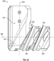
- Pipe isolation device 300 is moveable between the fully set position, as shown in Figure 24 , and the fully retracted position, as shown in Figures 25- 26 .
- Pipe isolation device 300 moves between the fully retracted position and the fully set position in a similar manner as described with respect to the pipe isolation device 100.
- Pipe isolation device 300 includes control bar head 102, a first sealing head 304, and a second sealing head 306.
- First sealing head 304 includes a first seal assembly 340 and the second sealing head 306 includes a second seal assembly 342.
- a center axis 380 extends through the sealing heads 304, 306 and is perpendicular a vertical axis 329 extending through the control bar head 102.
- the center axis 380 may form a centerline for a pipe in which the pipe isolation device 300 is deployed in the fully set position.
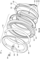
- First seal assembly 340 disassembled from the first main body 344 of the first sealing head 304 is shown.
- First main body 344 may have a cylindrical shape.
- First seal assembly 340 includes a first seal element 320, a first retaining ring 327, a first stiffening ring 337, and a first nose ring 324.
- Mechanical fasteners 346 such as screws or bolts, may be used in securing components of the first seal assembly 340 together.
- the mechanical fasteners 346 may extend through fastener openings 350 in the first retaining ring 327 and into mating attachment openings 352 in the first main body 344 to secure the first seal assembly 340 in an assembled position, as shown in Figures 24-26 .
- One attachment opening 352 in the first main body 344 is shown in Figure 27 .
- Seal elements 320, 322 may be bonded or glued in the seal assemblies 340, 342.
- the seal elements 320, 322 may be bonded or glued to the main bodies 344, 362, the nose rings 324, 326, and the retaining rings 327, 328.
- First main body 344 includes a first outer surface 354 extending around the circumference of the first main body 344.
- First outer surface 354 forms an outer diameter (OD) of the first main body 344.
- First main body 344 further includes a first face 356, also referred to as a primary first face, that extends radially from the first outer surface 354 and extends around the circumference of the first main body 344.
- First face 356 may be suitably transverse to the center axis 380, shown in Figure 24 , that extends through the sealing heads 104, 106. The transverse orientation of the first face 356 to the center axis 380 is continuous around the circumference of the first main body 344.
- First main body 344 further includes a second face 358, also referred to as a primary second face, that extends radially from the first main body 344 and extends around the circumference of the first main body 344.
- Second face 358 also may be suitably transverse to the center axis 380, as shown in Figure 27 , that extends through the sealing heads 104, 106.
- the transverse orientation of the second face 358 to the center axis 380 is continuous around the circumference of the first main body 344.
- Second main body 362 may have a cylindrical shape.
- Second seal assembly 342 may include a second seal element 322, a second retaining ring 328, a second stiffening ring 338, and a second nose ring 326.
- second seal element 322 has a seal front face formed by a second front face 349.
- Mechanical fasteners 346 such as screws, may be used in securing components of the second seal assembly 342 together.
- the mechanical fasteners 346 may extend through fastener openings 350 in the second retaining ring 328 and into mating attachment openings 352 in the second main body 362 to secure the second seal assembly 342 in an assembled position, as shown in Figures 24-26 .
- One attachment opening 352 in the second main body 362 is shown in Figure 28 .
- Seal elements 320, 322 may be bonded or glued in the seal assemblies 340, 342.
- the seal elements 320, 322 may be bonded or glued to the main bodies 344, 362, the nose rings 324, 326, and the retention rings 327, 328.
- the retaining rings 327, 328 may be split into several segments, and the stiffening rings 337, 338 may be made integral with the retaining rings 327, 328.
- Seal elements 320, 322 may also undergo a heat treatment, normalizing or softening process.
- Second main body 362 includes a second outer surface 364 extending around the circumference of the second main body 362. Second outer surface 364 forms an outer diameter (OD) of the second main body 362. Second main body 362 further includes a first face 366, also referred to as a secondary first face, that extends radially from the second outer surface 364 and extends around the circumference of the second main body 362. First face 366 may be suitably transverse to the center axis 380, shown in Figure 24 , that extends through the sealing heads 104, 106. The transverse orientation of the first face 366 to the center axis 380 is continuous around the circumference of the second main body 362.
- Second main body 362 further includes a second face 368, also referred to as a secondary second face, that extends radially from the second main body 362 and extends around the circumference of the second main body 362.
- second face 368 also may be suitably transverse to the center axis 380 that extends through the sealing heads 304, 306. The transverse orientation of the second face 368 to the center axis 380 is continuous around the circumference of the second main body 362.
- First seal assembly 340 has a first axially-offset configuration on the first sealing head 304. In the first axially-offset configuration, the first seal assembly 340 surrounds the first main body 344 in an elliptical shape, as shown in Figure 27 .
- a first bottom section 372 of the first seal assembly 340 is located on the first main body 344 at a bottom circumferential location on the circumference of the first main body 344 and at a first axial position parallel to the center axis 380.
- a first top section 374 of the first assembly 340 is positioned at a top circumferential location on the circumference of the first main body 344 and at a second axial position parallel to the center axis 380.
- First bottom section 372 may include component bottom sections of the first seal element 320, the first retaining ring 327, the first stiffening ring 337, and the first nose ring 324.
- First top section 374 may include component top sections of the first seal element 320, the first retaining ring 327, the first stiffening ring 337, and the first nose ring 324.
- the bottom circumferential location and the top circumferential location are opposite one another on the first main body 344. As shown in Figure 29 , the bottom circumferential location of the first bottom section 372 of the first seal assembly 340 is at a bottom portion of the first main body 344 and the top circumferential location of the first top section 374 of the first seal assembly 340 is at a top portion of the first main body 344.
- first assembly axis 376 is perpendicular to the center axis 380 and extends through the first bottom section 372.
- Second assembly axis 378 is perpendicular to the center axis 380 and extends through the first top section 374.
- first assembly axis 376 may extend through a center of the section of the first seal element 320 in the first bottom section 372.
- Second assembly axis 378 may extend through a center of the section of the first seal element 320 in the first top section 374.
- the axial-offset length for the axial-offset configuration of the first seal assembly 340 is designated as O A1 in Figure 29 .
- the axial-offset length O A1 is such that the first bottom section 372 is fully axially offset from the first top section 374 where the first bottom section 372 does not underlie any portion of the first top section 374.
- the component bottom sections of the first seal element 320, the first retaining ring 327, the first stiffening ring 337, and the first nose ring 324 are axially offset and do not underlie any portion of the component top sections of the first seal element 320, the first retaining ring 327, the first stiffening ring 337, and the first nose ring 324.
- the axial-offset length O A1 is such that the first bottom section 372 is partially axially offset from the first top section 374 where the first bottom section 372 underlies a portion of the first top section 374.
- second seal assembly 342 has a second axially-offset configuration on the second sealing head 306.
- the second seal assembly 342 surrounds the second main body 362 in an elliptical shape on the second main body 362.
- a second bottom section 384 of the second seal assembly 342 is located on the second main body 362 at the bottom circumferential location on the circumference of the second main body 362 and at a third axial position parallel to the center axis 380.
- a second top section 386 of the second seal assembly 342 is positioned at the top circumferential location on the circumference of the second main body 362 and at a fourth axial position parallel to the center axis 380.
- Second bottom section 384 may include component bottom sections of the second seal element 322, the second retaining ring 328, the second stiffening ring 338, and the second nose ring 326.
- Second top section 386 may include component top sections of the second seal element 322, the second retaining ring 328, the second stiffening ring 338, and the second nose ring 326.
- the bottom circumferential location and the top circumferential location on the circumference of the second main body 362 are opposite one another on the second main body 362. As shown in Figure 29 , the bottom circumferential location of the second bottom section 384 of the second seal assembly 342 is at a bottom portion of the second main body 362 and the top circumferential location of the second top section 386 of the second seal assembly 342 is at a top portion of the second main body 362.
- the axial-offset configuration of the second seal assembly 342 is illustrated by a third assembly axis 390 and a fourth assembly axis 392 shown in Figure 29 .
- Third assembly axis 390 is perpendicular to the center axis 380 and extends through the second bottom section 384.
- Fourth assembly axis 392 is perpendicular to the center axis 380 and extends through the second top section 386.
- the third assembly axis 390 may extend through a center of the section of the second seal element 322 in the second bottom section 384.
- Fourth assembly axis 392 may extend through a center of the section of the second seal element 322 in the second top section 386.
- the axial-offset length for the axial-offset configuration of the second seal assembly 342 is designated as O A2 in Figure 29 .
- the axial-offset length O A2 is such that the second bottom section 384 is fully axially offset from the second top section 386 where the second bottom section 384 does not underlie any portion of the second top section 386.
- the component bottom sections of the second seal element 322, the second retaining ring 328, the second stiffening ring 338, and the second nose ring 326 are axially offset and do not underlie any portion of the component top sections of the second seal element 322, the second retaining ring 328, the second stiffening ring 338, and the second nose ring 326.
- the axial-offset length O A2 is such that the second bottom section 384 is partially axially offset from the second top section 386 where the second bottom section 384 underlies a portion of the second top section 386.
- Seal assemblies 340, 342 are configured with axial-offset configurations to help provide the compact sealing heads 304, 306 that allow for a compact deployed length L D for the pipe isolation device 300. As discussed previously, limiting the deployed length L D helps prevent damage to a pipe due to the reaction loads of the pipe isolation device 300 against the pipe during operation of the pipe isolation device 300 in the pipe.
- pipe isolation devices may have seal elements that are circular and mounted on sealing heads such that the seal elements have perpendicular configurations without an axial offset.
- First seal element 320 may be made of an elastomeric material and may be stretchable. First seal element 320 may be stretched during assembly to mount the first seal element 320 on the first main body 344. First seal element 320 is in the installed configuration where the first seal element has been stretched to form an elliptical shape and is mounted on the first main body 344.
- First seal element may have an uninstalled configuration where the first seal element has a circular shape and has not been stretched and mounted on the first main body 344.
- the first seal element When being installed on the first main body 344, the first seal element may be stretched from the circular position to the elliptical position to mount the first seal element on the first main body 344.
- the first seal element is twisted and stretched when positioning the first seal element from the uninstalled configuration to the installed configuration so that the first seal element has a perpendicular configuration, as described below.
- First seal element 320 includes a base section 396, an extension section 398, and a flair section 402.
- Base section 396 as shown in Figure 31 , has an inner surface 404, a first ledge 406, and a second ledge 408 that extend around a first seal opening 410.
- Inner surface 404 is configured to abut against the first main body 344 when the first seal element 320 is assembled on the first sealing head 304.
- Inner surface 404 forms the inner diameter (ID) of the first seal element 320.
- First ledge 406 forms a first outer surface 412 and second ledge 408 forms a second outer surface. 414.
- Outer surfaces 412, 414 may be parallel to the inner surface 404 of the base section 396.
- a stiffening ring pocket 416 is formed by the first ledge 406 and the extension section 398 and configured for the stiffening ring 338 to fit therein and extend around the first ledge 406.
- Extension section 398 is formed radially between the base section 396 and the flair section 402 and extends outwards from the base section 396.
- Flair section 402 includes a seal outer surface 420 that extends around seal opening 410. Seal outer surface 420 forms the outer diameter (OD) of the first seal element 320.
- Extension section 398 further has a seal back face 422 that may extend from the base section 396 to the seal outer surface 420. Seal back face 422 is the non-pressurized side of the seal element 320.
- an anti-extrusion device is used with the first seal element 320.
- the anti-extrusion device is formed by a garter spring 424.
- Garter spring 424 may be embedded in the first seal assembly 320. Ends of the garter spring 424 are shown in Figure 31 .
- the garter spring 424 may be formed by a coil spring that may fully encircle the seal opening 410.
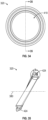
- First retaining ring 327 may be made of a metallic material.
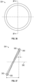
- First retaining ring 327 has an elliptical shape.
- Figure 33 shows the orientation of the first retaining ring 327 when assembled on the pipe isolation device 300 in the fully set position, as shown in Figure 29 .
- First retaining ring 327 is shown in an installed orientation as if it were mounted on the first main body 344 with the center axis 380 extending through a retaining opening of the first retaining ring.
- First retaining ring may have a ring support face 360 that is perpendicular to the center axis 380 when in the assembled position. Ring support face 360 abuts against one side of the first seal element 320 to support the first seal element in a perpendicular configuration in the assembled position. Ring support face 360 continues around the circumference of the first retaining ring and is continuously perpendicular to the center axis 380 in the assembled position.
- first seal element 320 is shown.
- Second seal element 322 may be configured in a similar manner as the embodiment described with respect to the first seal element 320 shown in Figures 34-35 .
- first seal element 320 may be made of an elastomeric material that may be stretched.
- Figure 35 shows the orientation of the first seal element 320 when assembled on the pipe isolation device 300 in the fully set position, as shown in Figure 29 .
- First seal element 320 is shown in an installed orientation as if it were mounted on the first main body 344 with the center axis 380 extending through the seal opening 410 of the first seal element 320.
- the cross-section of the first seal assembly 320 has a perpendicular configuration to the center axis 380 when in the assembled position.
- the cross-section of the first seal assembly has a continuous perpendicular configuration to the center axis 380 around the circumference of the first main body 344 when in the assembled position.
- Seal elements 320, 322 may be manufactured (typically molded) in a circular ring shape. Seal elements 320, 322 may be stretched into a twisted elliptical ring shape when installed on the main bodies 344, 362 of the seal assemblies 340, 342, as shown in Figure 35 . The stretched shape of the seal elements 320, 322 maintains a cross-section which is perpendicular to the pipe internal diameter around the circumference of the seal elements 320, 322, even though the tops of the seal elements 320, 322 are seated at a position further axially down the pipe than where the bottoms of the seal elements 320, 322 are seated, as described with respect to Figure 29 .
- a first garter spring 424 may be embedded in the body of the first seal element 320 and may be made of a metallic material. Ends of the first garter spring 424 may linked with like material or a seamless spring may be used. Garter spring 424 may be installed with no preload.
- First nose ring 324 may be configured in a similar manner as the embodiment described with respect to the first nose ring 324 shown in Figures 36-37 .
- First nose ring 324 may be made of a metallic material and may have an elliptical shape.
- Figure 37 shows the orientation of the first nose ring 324 when assembled on the pipe isolation device 300 in the fully set position, as shown in Figure 29 .
- First nose ring 324 is shown in an installed orientation as if it were mounted on the first main body 344 with the center axis 380 extending through a nose ring opening of the first nose ring 324.
- first nose ring 324 has a first nose face 382 and a second nose face 383 that are perpendicular to the center axis 380 when in the assembled position.
- First nose face 382 abuts against one side of the first seal element 320 and second nose face 383 abuts against a face of the first main body 344 to support the first seal element 320 in a perpendicular configuration in the assembled position, see Figures 37-41 .
- First nose face 382 and the second nose face 383 continue around the circumference of the first nose ring 324 and are continuously perpendicular to the center axis 380 in the assembled position.
- FIG. 38 a cross-sectional view of the pipe isolation device 300 is shown in the fully set position.
- a cross-sectional view of the first seal assembly 340 is circled and Figure 39 is an enlarged cross-sectional view of the circled area " 39 " in Figure 38 .
- a cross-sectional view of the second seal assembly 342 is circled and Figure 40 is an enlarged cross-sectional view of the circled area " 40 " in Figure 38 .
- a first parallel axis 394 is shown extending through the circled area " 39 " and the circled area " 40 ". First parallel axis 394 is parallel to the center axis 380.
- first seal assembly 340 on the first sealing head 304 is shown.
- the internal diameter of the base section 396 of the first seal element 320 abuts the first outer surface 354, shown in Figure 27 , of the first main body 344.
- first seal element 320 is configured to have a perpendicular configuration with respect to the first parallel axis 394.
- Extension section 398 extends radially outwards from the base section 396 and in a direction perpendicular to the first parallel axis 394 to form the perpendicular configuration.
- the perpendicular configuration of the first seal element is formed continuously around the first main body 344.
- Stiffening ring 337 may be disposed in the stiffening ring pocket 416 and extends around the seal opening 410, shown in Figures 30-31 , to provide additional strength to the first seal element 320.
- First retaining ring 327 may be disposed on one side of the first seal element 320 to secure the stiffening ring 337 and the first seal element 320 in place on the first main body 344. First retaining ring 327 may abut against the stiffening ring 337 and the first seal element 320 to block the stiffening ring pocket 416, shown in Figure 31 .
- First retaining ring 327 may extend from a surface of the first main body 344 that is at a non-parallel angle with respect to the first parallel axis 394 so that the first retaining ring 327 extends at an angle from the first main body 344 towards the first sealing element 320.
- First seal element 320 and first retaining ring 327 may have a first inter-locking feature where the first retaining ring 327 has a surface that extends over and abuts the first ledge 406.
- First nose ring 324 extends radially outwards from the first main body 344 and adjacent a side of the first sealing element 320. First nose ring 324 may abut the side of the first seal element 320.
- First seal element 320 and first nose ring 324 may have a second inter-locking feature where the first nose ring 324 has a surface that extends over and abuts the second ledge 408.
- First nose ring 324 may extend radially from the first main body 344 in a perpendicular direction with respect to first parallel axis 394 and may be disposed adjacent to the garter spring 424 in the first sealing element 320.
- First sealing element 320 may further include an internal diameter (ID) sealing feature for providing a second seal between the first sealing element 320 and the first main body 344 of the first sealing head 304.
- ID sealing feature provides an interference fit and may be located on the front, back, or ID of the first seal element 322.
- the ID sealing feature may seal against the first main body 344, the first nose ring 324, or the first retaining ring 327.
- the ID sealing feature is formed by a first ID sealing ring 426 that extends from the ID of the first sealing element 320.
- First ID sealing ring 426 may be integral with the first sealing element 320 or may be a separate ring that extends around the first main body 344.
- First sealing element 320 is disposed between the first retaining ring 327 and the first nose ring 324 to secure the first sealing element 320 in place around the first main body 344.
- Mechanical fasteners may be used to press the first retaining ring 327 and the first nose ring 324 against the first seal element 320 to press fit the first seal element 320 in place on the first main body 344.
- second seal assembly 342 on the second sealing head 306 is shown.
- Embodiments of the second seal assembly disclosed may be used on the first sealing head 104 and/or the second sealing head 106.
- the inner diameter of base section 396 of the second seal element 322 abuts the second outer surface 364, shown in Figure 28 , of the second main body 362.
- second seal element 322 is configured to have a perpendicular configuration with respect to the first parallel axis 394.
- Extension section 398 extends radially outwards from the base section 396 and in a direction perpendicular to the first parallel axis 394 to form the perpendicular configuration.
- the perpendicular configuration of the second seal element 322 is formed continuously around the second main body 362.
- Second stiffening ring 338 is disposed in the stiffening ring pocket 416 and extends around the seal opening 410, shown in Figures 30-31 , to provide additional strength to the second seal element 322.
- Second retaining ring 328 is disposed on one side of the second sealing element 322 to secure the second stiffening ring 338 and the second seal element 322 in place on the second main body 362. Second retaining ring 328 may abut against the second stiffening ring 338 and the second seal element 322.
- Second retaining ring 328 may extend from a surface of the second main body 362 that is at a non-parallel angle with respect to the first parallel axis 394 so that the second retaining ring 328 extends at an angle from the second main body 362 towards the second sealing element 322.
- Second nose ring 326 extends radially outwards from the second main body 362 and adjacent a side of the second sealing element 322. Second nose ring 326 may abut a side of the second seal element 322. Second nose ring 326 may extend radially from the second main body 362 in a perpendicular direction with respect to first parallel axis 394 and may be disposed adjacent to a second garter spring 425 in the second sealing element 322. Second sealing element 322 is disposed between the second retaining ring 328 and the second nose ring 326 to secure the second sealing element 322 in place around the second main body 362. Mechanical fasteners may be used to press the second retaining ring 328 and the second nose ring 326 against the second seal element 322 to press fit the second seal element 322 in place on the second main body 362.
- Second sealing element 322 may further include an internal diameter (ID) sealing feature for providing a second seal between the second sealing element 322 and the second main body 362 of the second sealing head 306.
- ID sealing feature provides an interference fit and may be located on the front, back, or ID of the first seal element 322.
- the ID sealing feature may seal against the second main body 362, the second nose ring 326, or the second retaining ring 328.
- the ID sealing feature is formed by a second sealing ring 428 that extends from the ID of the second sealing element 322.
- Second sealing ring 428 may be integral with the second sealing element 322 or may be a separate ring that extends around the second main body 362.
- FIG. 38 and 41 an embodiment of the first seal assembly 340 on the first sealing head 304 in a pipe 12 is shown.
- the embodiment disclosed with respect to Figure 41 is shown assembled on the first sealing head 304 but may also be assembled on the second sealing head 306.
- the OD of the seal element 320 provides an interference fit in the pipe which forms a seal.
- the frontside of the seal element 320 is the pressurized side, while the backside of the seal element 320 is the non-pressurized side.
- Fluid pressure in the pipe 12 is shown directed in a forward direction by arrow 418.
- First front face 348 is disposed on the pressurized side of the first seal element 320.
- the internal diameter of the base section 396 of the first seal element 320 abuts the first outer surface 354, shown in Figure 27 , of the first main body 344.
- the ID of the first seal element 320 sits on the cylindrical surface of the first main body 344 of the first sealing head 304.
- the cylindrical surface of the first main body 344 in which the seal element 320 seats forms part of a gland.
- the gland includes surfaces 354, 356, as well as the seal-side surfaces of the retaining ring 327 and nose ring 324.
- the gland conforms to the stretched shape of the seal element 320.
- Seal element 320 sits between the first nose ring 324 (on the back side of the seal element 320 ) and the first retainer ring 327 (on the frontside of the seal element 320 ).
- First seal element 320 includes an embodiment of the ID sealing feature formed by an ID sealing ring 430 disposed between the base section 396 of the first seal element 320 and the primary first face 356 of the first main body 344.
- ID sealing ring 430 may be integral with the first seal element 320 or a separate ring extending around the first main body 344.
- ID sealing ring 430 is shown extending beyond the primary first face 356 to better illustrate the location of the ID sealing ring 430 that abuts against the primary first face 356 and is disposed between the first sealing element 320 and the primary first face 356.
- First retention ring 327 and first stiffening ring 337 are configured in a similar manner as described with respect to the embodiments disclosed in Figures 39-40 .
- First nose ring 324 extends radially outwards from the first main body 344 and adjacent a side of the first sealing element 320. A section of the ID of the nose ring 324 is supported by a body shoulder 434 of the first main body 344. In other words, a side of the first nose ring 324 abuts against an outer diameter (OD) of the body shoulder 434 and the primary second face 358 of the body shoulder 434. Nose ring 324 may also extend beyond the shoulder 434 to extend radially outwards from the base section 396 of the first seal element 320 to form an inter-locking feature.
- the garter spring 424 resists expansion and is configured to have an OD that is greater than the height of the extrusion gap so that the garter spring 424 is obstructed from passing through the extrusion gap 436 to help prevent extrusion of the first seal element 320.
- Seal elements 320, 322 as assembled on the sealing heads 304, 306 have advantages.
- the geometry of the seal elements 320, 322 makes manufacturing and inspection more economical.
- the seal cross-section maintains the same shape around the circumference of the seal elements 320, 322. This simplifies analysis of the seal elements 320, 322, and produces a more reliably uniform seal.
- the ring shape of the seal elements 320, 322 allows for a singular main piece for the main bodies 344, 362 of the seal heads 304, 306 rather than a bolted-together seal head. This reduces leak paths and reduces the high-stress points in the seal head mechanism. It removes any high-stressed fasteners which would be potential failure points.
- the perpendicular gland on each of the main bodies 344, 362 is easier to machine into the main bodies 344, 362 of the seal heads 304, 306. Variable, acute to obtuse shaped glands are more complicated to machine.
- a cross-section of the third seal element 520 may be approximated to form a variable trapezoidal shape from acute to obtuse around the profile of the third seal element 520, due to the angle of the seal gland in order to fit on the first main body 344 of the first sealing head 304.
- the OD of the third seal head 520 is variable around the circumference to maintain the proper interference with the pipe ID.
- the third seal element 520 may be assembled on the first main body 344 in a manner like the first seal element 320.
- the third seal element 520 sits between a first nose ring 324 (on the back side of the third seal element 520 ) and a first retainer ring 327 (on the front side of the third seal element 520 ).
- the front side of the third seal element 520 is the pressurized side, while the back side of the third seal element 520 is the non-pressurized side.
- the ID of the third seal element 520 sits on the cylindrical surface of the first main body 344 of the first sealing head 304.
- the OD of the third seal element provides an interference fit in the pipe which forms a seal.
- a second seal is formed by an ID sealing feature. This feature provides an interference fit and may be located on the front, back, or ID of the third seal element 520, and may seal against the first main body 344, the first nose ring 324, or the first retaining ring 327.
- a first stiffening ring 337 or other stiffening options discussed with respect to disclosed embodiments may be applied and used with the third seal element 520.
- the third seal element 520 is squeezed between two plates which are secured with one or more fasteners to the first sealing head 304.
- the third seal element 520 may include seal rings around each fastener or a circumferential seal ring 525 which encompasses all the fasteners.
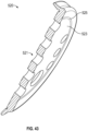
- Fastener holes 521 extend through the disc body 523 of the third seal element 520, as shown in Figures 42-43 .
- Third seal element 520 has advantages. Third seal 520 helps prevent failure due to "bunching" when being installed due to the inherent locking nature of the parallelogram trapezoidal shaped gland. A third seal element 520 having a full-disc style seal can be held in place very robustly. Bunching issues are eliminated. Since the third seal element does not need to be stretched, installation on the first sealing head 304 is simplified.
- Embodiments of the seal heads disclosed herein provides advantages over other seal heads that use cylindrically-shaped seal heads which are either inserted through a pipe branch on an angle and rotated into position, or smaller than pipe ID seals which need to be actuated.
- the geometry required for the seal heads for use in the sliding engagement mechanism of the pipe isolation device disclosed herein benefit from the seal assemblies disclosed herein.
- Embodiments of the seal heads disclosed employ cylindrical seal heads that have a slanted shape to allow for clearance to be deployed through a circular branch opening of a pipe that is smaller than the OD of the pipe to be sealed.
- Embodiments of the seal elements can then be deployed axially down the pipeline without the need for rotating the sealing heads with the seal elements into position.
- Rings forming the seal assemblies may be changed along with the seal elements with different OD variations to allow the seal head to adapt to a range of pipe wall thicknesses.
- the rings are sized to provide enough clearance to prevent interference between the pipe ID and ring OD, while also reducing the radial gap between the pipe ID and ring OD to an amount that is manageable with aid from an anti-extrusion device.
- Extrusion resistance may be provided by any of the following anti-extrusion devices: a garter spring, fabric reinforcement, shielded backing, or a flexible ring.
- the movement of the seal elements through the pipe is axial, so having a reduced diameter on the backside of the seal element is advantageous.
- Embodiments of the pipe isolation device may be configured to translate the right angle at a lateral access opening and to provide a compact tool by providing sliding engagements to withstand the challenging environments of pipelines, including high pressures, high temperatures, and different types of fluids.
- the pipe isolation device of the present disclosure may be modified by adding additional sealing heads to become a triple, or more, block and bleed apparatus.
- the sealing feature for the seal head side of the seal on the back of the seal has advantages.
- the bolting force from the retaining ring forms an initial seal.
- the contact pressure also increases between this sealing feature and the seal head.
Landscapes
- Engineering & Computer Science (AREA)
- General Engineering & Computer Science (AREA)
- Mechanical Engineering (AREA)
- Quick-Acting Or Multi-Walled Pipe Joints (AREA)
- Sealing Devices (AREA)
Claims (15)
- Rohrisoliervorrichtung, umfassend:einen Steuerstangenkopf (102);einen ersten Dichtkopf (304) mit einem ersten Dichtelement (320) und einem ersten Gleiteingriff, wobei der erste Gleiteingriff es dem ersten Dichtkopf ermöglicht, relativ zum Steuerstangenkopf auf einem ersten festen Weg zu gleiten und einen rechten Winkel zu durchqueren, um Zugang zu einem Innenraum eines Rohres mit einer eine Axialrichtung definierenden Mittelachse (380) zu erhalten;einen zweiten Dichtkopf (306) mit einem zweiten Dichtelement (322) und einem zweiten Gleiteingriff, wobei der zweite Gleiteingriff es dem zweiten Gleitkopf ermöglicht, an dem ersten Dichtkopf auf einem zweiten festen Weg zu gleiten und den rechten Winkel zu durchqueren, um Zugang zu einem Innenraum des Rohres zu erhalten;wobei das auf dem ersten Dichtkopf (304) angeordnete erste Dichtelement (320) eine erste axial versetzte Konfiguration aufweist; undwobei das auf dem zweiten Dichtkopf (322) angeordnete zweite Dichtelement (322) eine zweite axial versetzte Konfiguration aufweist;wobei das erste Dichtelement eine durch eine Schlauchfeder (424) gebildete Extrusionsschutzvorrichtung umfasst.
- Rohrisoliervorrichtung nach Anspruch 1, bei der der erste Gleiteingriff konfiguriert ist, um es dem ersten Dichtkopf (304) zu ermöglichen, auf dem ersten festen Weg von einer ersten zurückgezogenen Position zu einer ersten Einstellposition zu gleiten, um den rechten Winkel zu durchlaufen, und der zweite Gleiteingriff konfiguriert ist, um es dem zweiten Dichtkopf (306) zu ermöglichen, auf dem zweiten festen Weg von einer zweiten zurückgezogenen Position zu einer zweiten Einstellposition zu gleiten, um den rechten Winkel zu durchlaufen, und bei der das erste Dichtelement (320) und das zweite Dichtelement (322) eine elliptische Form aufweisen.
- Rohrisoliervorrichtung nach Anspruch 2, bei der der erste Gleiteingriff eine erste Führungsschiene (111) und ein erstes Führungselement (112) umfasst, die gleitend miteinander verbunden sind, und bei der der zweite Gleiteingriff eine zweite Führungsschiene (114) und ein zweites Führungselement (116) umfasst, die gleitend miteinander verbunden sind.
- Rohrisoliervorrichtung nach Anspruch 3, bei der der erste Dichtkopf (304) in der ersten zurückgezogenen Position und der zweite Dichtkopf (306) in der zweiten zurückgezogenen Position sich in einer vollständig zurückgezogenen Position befinden, in der der erste Dichtkopf und der zweite Dichtkopf eine Ausrichtung in einer Linie mit dem Steuerstangenkopf (102) aufweisen, und bei der der erste Dichtkopf in der ersten Einstellposition und der zweite Dichtkopf in der zweiten Einstellposition in einer vollständig eingestellten Position sind, in der der erste Dichtkopf und der zweite Dichtkopf eine miteinander fluchtende Ausrichtung aufweisen.
- Rohrisoliervorrichtung nach Anspruch 3, bei der die Mittelachse (380) sich in der vollständig eingestellten Position durch den ersten Dichtkopf (304) und den zweiten Dichtkopf (306) erstreckt, und bei der die erste Führungsschiene (110) und die zweite Führungsschiene (114) unter einem spitzen Winkel zur horizontalen Achse stehen, wenn sich der erste Dichtkopf und der zweite Dichtkopf in der vollständig eingestellten Position befinden.
- Rohrisoliervorrichtung nach Anspruch 2, die ferner einen ersten Verriegelungsmechanismus (150) mit einem ersten Verriegelungszustand, der konfiguriert ist, um den ersten Dichtkopf (304) in der ersten zurückgezogenen Position zu verriegeln, und mit einem ersten Entriegelungszustand, der es dem ersten Dichtkopf ermöglicht, von der ersten zurückgezogenen Position in die erste Einstellposition zu gleiten, umfasst, und die ferner einen zweiten Verriegelungsmechanismus (152) mit einem zweiten Verriegelungszustand, der konfiguriert ist, um den zweiten Dichtkopf (306) in der zweiten zurückgezogenen Position zu verriegeln, und mit einem zweiten Entriegelungszustand, der es dem zweiten Dichtkopf ermöglicht, von der zweiten zurückgezogenen Position zu der zweiten eingestellten Position zu gleiten, umfasst.
- Rohrisoliervorrichtung nach Anspruch 6, bei der der zweite Verriegelungsmechanismus (152) in den zweiten Verriegelungszustand vorgespannt ist und aus dem zweiten Verriegelungszustand als Reaktion darauf, dass eine erste aufgebrachte Kraft einen ersten Kraftschwellenwert erreicht, in den zweiten Entriegelungszustand freigegeben wird, und bei der der erste Verriegelungsmechanismus (150) in den ersten Verriegelungszustand vorgespannt ist und aus dem ersten Verriegelungszustand als Reaktion darauf, dass eine zweite aufgebrachte Kraft einen zweiten Kraftschwellenwert erreicht, in den ersten Entriegelungszustand freigegeben wird.
- Rohrisoliervorrichtung nach Anspruch 7, bei der der erste Kraftschwellenwert niedriger als der zweite Kraftschwellenwert ist.
- Rohrisoliervorrichtung nach Anspruch 7, bei der der zweite Verriegelungsmechanismus (152) einen zweiten Stift (172) oder eine zweite Klinke (166) umfasst, die konfiguriert sind, um den zweiten Verriegelungsmechanismus aus dem zweiten Verriegelungszustand in den zweiten Entriegelungszustand freizugeben, und bei der der erste Verriegelungsmechanismus (150) einen ersten Stift (170) oder eine erste Klinke (158) umfasst, die konfiguriert sind, um den ersten Verriegelungsmechanismus aus dem ersten Verriegelungszustand in den ersten Entriegelungszustand freizugeben.
- Rohrisoliervorrichtung nach Anspruch 1, bei der das erste Dichtelement (320) entlang eines ersten Außenumfangs des ersten Dichtkopfes (104) angeordnet ist, um ein erstes UmfangsDichtelement (322) zu bilden, und bei der das zweite Dichtelement entlang eines zweiten Außenumfangs des zweiten Dichtkopfes (106) angeordnet ist, um ein zweites UmfangsDichtelement zu bilden.
- Verfahren zum Isolieren eines Rohrs, wobei das Verfahren umfasst:Fördern eines ersten Dichtkopfs (304) und eines auf dem ersten Dichtkopf verschiebbaren zweiten Dichtkopfs (306) in einer vollständig zurückgezogenen Position durch eine seitliche Zugangsöffnung in dem Rohr, wobei der erste Dichtkopf verschiebbar mit einem Steuerstangenkopf (102) verbunden ist und der zweite Dichtkopf verschiebbar mit dem ersten Dichtkopf verbunden ist;Verschieben des ersten Dichtkopfes entlang eines ersten Gleiteingriffs und Verschieben des zweiten Dichtkopfes entlang eines zweiten Gleiteingriffs in eine vollständig eingestellte Position, während der Steuerstangenkopf seine Bewegung durch die seitliche Zugangsöffnung fortsetzt, wobei der erste Dichtkopf und der zweite Dichtkopf in der vollständig eingestellten Position jeweils eine Dichtung in dem Rohr bilden, wobei das Rohr eine Mittelachse (380) aufweist, die eine Axialrichtung definiert;Verriegeln des ersten Dichtkopfes und des zweiten Dichtkopfes in der vollständig zurückgezogenen Position mit einem Verriegelungsmechanismus (150, 152) in einem verriegelten Zustand, während sich der erste Dichtkopf und der zweite Dichtkopf durch die seitliche Zugangsöffnung bewegen;Freigeben des Verriegelungsmechanismus aus dem Verriegelungszustand in den Entriegelungszustand als Reaktion auf eine ausgeübte Kraft, wenn der Steuerstangenkopf durch die seitliche Zugangsöffnung befördert wird, um es dem ersten Gleitkopf und dem zweiten Gleitkopf zu ermöglichen, sich in die vollständig eingestellte Position zu bewegen;wobei ein erstes Dichtelement (320) an dem ersten Dichtkopf angeordnet ist und das erste Dichtelement eine erste axial versetzte Konfiguration aufweist;wobei ein zweites Dichtelement (322) an dem zweiten Dichtkopf angeordnet ist und das zweite Dichtelement eine zweite axial versetzte Konfiguration aufweist; undwobei das erste Dichtelement eine durch eine Schlauchfeder (424) gebildete Extrusionsschutzvorrichtung umfasst.
- Verfahren nach Anspruch 11, bei dem das Verriegeln des ersten Dichtkopfs (204) und des zweiten Dichtkopfs (306) in der vollständig zurückgezogenen Position ferner das Verriegeln des ersten Dichtkopfs in einer ersten zurückgezogenen Position in einem ersten verriegelten Zustand mit einem ersten Verriegelungsmechanismus (150) und das Verriegeln des zweiten Dichtkopfs in einer zweiten zurückgezogenen Position in einem zweiten verriegelten Zustand mit einem zweiten Verriegelungsmechanismus (152) umfasst, und wobei das erste Dichtelement (320) und die zweiten Dichtelemente (322) elliptische Formen aufweisen.
- Verfahren nach Anspruch 12, bei dem das Lösen des Verriegelungsmechanismus aus dem verriegelten Zustand in den entriegelten Zustand ferner das Lösen des zweiten Verriegelungsmechanismus (152) aus dem zweiten verriegelten Zustand in einen zweiten entriegelten Zustand als Reaktion auf eine erste ausgeübte Kraft und das Lösen des ersten Verriegelungsmechanismus (150) aus dem ersten verriegelten Zustand in einen ersten entriegelten Zustand als Reaktion auf eine zweite ausgeübte Kraft umfasst.
- Verfahren nach Anspruch 13, bei dem der zweite Dichtkopf (306) an einer Innenwand (3) des Rohrs in Eingriff kommt, wenn der zweite Dichtkopf durch die seitliche Zugangsöffnung befördert wird, so dass die erste aufgebrachte Kraft auf den ersten Verriegelungsmechanismus (150) einwirkt, und bei dem der erste Dichtkopf (304) an der Innenwand des Rohrs in Eingriff kommt, wenn der erste Dichtkopf durch die seitliche Zugangsöffnung befördert wird, so dass die zweite aufgebrachte Kraft auf den ersten Verriegelungsmechanismus einwirkt.
- Verfahren nach Anspruch 14, bei dem der zweite Dichtkopf (306) in den zweiten Entriegelungszustand freigegeben wird, bevor der erste Dichtkopf (304) in den ersten Entriegelungszustand freigegeben wird, und bei dem der erste Kraftschwellenwert kleiner als der zweite Kraftschwellenwert ist.
Applications Claiming Priority (2)
| Application Number | Priority Date | Filing Date | Title |
|---|---|---|---|
| US201962949089P | 2019-12-17 | 2019-12-17 | |
| PCT/US2020/065221 WO2021126913A1 (en) | 2019-12-17 | 2020-12-16 | Pipe isolation device with seal |
Publications (3)
| Publication Number | Publication Date |
|---|---|
| EP4078006A1 EP4078006A1 (de) | 2022-10-26 |
| EP4078006A4 EP4078006A4 (de) | 2024-01-10 |
| EP4078006B1 true EP4078006B1 (de) | 2025-05-14 |
Family
ID=76477902
Family Applications (1)
| Application Number | Title | Priority Date | Filing Date |
|---|---|---|---|
| EP20902764.8A Active EP4078006B1 (de) | 2019-12-17 | 2020-12-16 | Rohrisoliervorrichtung mit dichtung |
Country Status (4)
| Country | Link |
|---|---|
| US (1) | US12442478B2 (de) |
| EP (1) | EP4078006B1 (de) |
| CA (1) | CA3160523A1 (de) |
| WO (1) | WO2021126913A1 (de) |
Family Cites Families (31)
| Publication number | Priority date | Publication date | Assignee | Title |
|---|---|---|---|---|
| US762436A (en) * | 1902-09-29 | 1904-06-14 | Alfred G Osgood | Valve. |
| US791173A (en) * | 1904-03-29 | 1905-05-30 | Clarence E Anglim | Valve. |
| US936454A (en) * | 1907-10-03 | 1909-10-12 | Eugene D Jefferson | Gate-valve. |
| US1000617A (en) * | 1911-03-13 | 1911-08-15 | H J Brubaker | Valve. |
| US1686057A (en) * | 1926-05-03 | 1928-10-02 | Cons Ashcroft Hancock Co | High-pressure gate valve |
| US1985078A (en) * | 1933-02-24 | 1934-12-18 | Au Vo Col Corp | Valve |
| US2328661A (en) * | 1941-03-10 | 1943-09-07 | Joseph F Maloney | Breaking device |
| US2600115A (en) * | 1946-05-15 | 1952-06-10 | Sr Edward Albert Kliewer | Valve |
| US2906295A (en) * | 1957-07-01 | 1959-09-29 | Williamson Inc T | Pipe line plugger |
| US3025885A (en) * | 1959-03-16 | 1962-03-20 | Williamson Inc T | Pipe line plugger |
| GB1340431A (en) * | 1971-03-30 | 1973-12-12 | Pass & Co Ltd | Pipe line plugger |
| US4682631A (en) * | 1986-04-03 | 1987-07-28 | The United States Of America As Represented By The Secretary Of The Navy | Sealing apparatus for a valve body opening |
| FR2733021B1 (fr) | 1995-04-13 | 1997-06-06 | Joint Francais | Joint et son procede de montage |
| US5730444A (en) | 1996-03-08 | 1998-03-24 | Skf Usa Inc. | Seal with embedded garter spring |
| JPH1061564A (ja) | 1996-08-20 | 1998-03-03 | Atsushi Imai | 螺旋状シールを利用したポンプ |
| US7080820B2 (en) | 1999-11-16 | 2006-07-25 | Fisher Controls International Llc. | Elliptical sealing surface for butterfly valve |
| US6289935B1 (en) * | 2000-08-25 | 2001-09-18 | George Tash | Drainpipe test plug device |
| US6659133B2 (en) * | 2001-02-06 | 2003-12-09 | Larry R. Russell | Insertable line stopper plug for pipelines |
| DE602004013304T2 (de) * | 2003-05-02 | 2009-05-20 | TDW Delaware, Inc., Wilmington | Vorrichtungen, systeme und verfahren zum absperren eines hochtemperaturrohrs |
| US8404029B2 (en) | 2007-06-14 | 2013-03-26 | Donaldson Company, Inc. | Crankcase ventilation filter arrangments; components; and, methods |
| CN103721492B (zh) | 2007-06-14 | 2016-01-06 | 唐纳森公司 | 曲轴箱通风过滤器装置、部件和方法 |
| US8307856B2 (en) * | 2007-11-07 | 2012-11-13 | Tdw Delaware Inc. | Double block and bleed plug |
| US7841364B2 (en) * | 2007-11-07 | 2010-11-30 | Tdw Delaware, Inc. | Double block and bleed plug |
| US7766047B1 (en) * | 2009-01-09 | 2010-08-03 | Tdw Delaware Inc. | Telescoping double blocking pipe plug |
| KR101060729B1 (ko) * | 2010-03-12 | 2011-08-31 | 주식회사 한국가스기술공사 | 배관차단용 이중 플러깅 헤드 |
| KR101191394B1 (ko) * | 2010-05-20 | 2012-10-15 | 왕일우 | 핫 태핑 스토핑머신 |
| US9494245B1 (en) | 2013-03-15 | 2016-11-15 | Humphrey Products Company | Over-molded valve stem and method of making a valve stem for a valve assembly |
| US20140283926A1 (en) * | 2013-03-19 | 2014-09-25 | Joshua Duell | Foldable, Double-Block and Bleed Plugging Tool |
| JP6793295B2 (ja) * | 2016-03-29 | 2020-12-02 | 株式会社テクノクラーツ | 運動伝達装置、成形用金型及び機械類 |
| HUE059841T2 (hu) * | 2018-06-22 | 2023-01-28 | Tdw Delaware Inc | Befeszített tömítéssel ellátott leválasztódugó |
| EP3844431B1 (de) * | 2018-08-30 | 2024-07-24 | Team Industrial Services Inc. | Rohrisoliervorrichtung |
-
2020
- 2020-12-16 US US17/784,943 patent/US12442478B2/en active Active
- 2020-12-16 CA CA3160523A patent/CA3160523A1/en active Pending
- 2020-12-16 WO PCT/US2020/065221 patent/WO2021126913A1/en not_active Ceased
- 2020-12-16 EP EP20902764.8A patent/EP4078006B1/de active Active
Also Published As
| Publication number | Publication date |
|---|---|
| EP4078006A4 (de) | 2024-01-10 |
| EP4078006A1 (de) | 2022-10-26 |
| US20230022125A1 (en) | 2023-01-26 |
| CA3160523A1 (en) | 2021-06-24 |
| US12442478B2 (en) | 2025-10-14 |
| WO2021126913A1 (en) | 2021-06-24 |
Similar Documents
| Publication | Publication Date | Title |
|---|---|---|
| US11603956B2 (en) | Pipe isolation device | |
| US4348039A (en) | Release coupling | |
| EP0579393B1 (de) | Verfahren und Vorrichtung zum Abdichten von Bohrlochköpfen | |
| EP0084940B1 (de) | Aufweitvorrichtung mit elastisch deformierbaren Elementen | |
| US7240697B2 (en) | Apparatus and method for isolating and testing a segment of pipelines | |
| US12117080B2 (en) | Gasket assembly and seal carrier | |
| JPS63203974A (ja) | ゲ−ト・バルブ | |
| WO2007000023A1 (en) | A fluid coupling | |
| EP1631764B1 (de) | Flexible gasleitungskupplung | |
| EP0999339A2 (de) | Metall auf Metall Dichtungsanordnung für Vorrichtung für die Produktion von Öl und Gas | |
| US11698159B2 (en) | Combination pipe seal and grips | |
| EP4241010A1 (de) | Isolierwerkzeug und verfahren zur isolierung eines abschnitts eines rohrs oder eines behälters | |
| US12442478B2 (en) | Pipe isolation device with seal | |
| US20160193672A1 (en) | Pipe isolation & intervention | |
| US6123104A (en) | Undersea hydraulic coupling with Y-seal | |
| KR101972968B1 (ko) | 파이프 연결용 어셈블리 | |
| WO2026038055A1 (en) | Isolation tool and method for isolating a pipe | |
| CA2613896C (en) | Gate valve with tongue and groove or bridging seal to annular seat elements | |
| WO2002001176A1 (en) | Tubular isolation | |
| GB2215805A (en) | Displaceable valve assembly or pig |
Legal Events
| Date | Code | Title | Description |
|---|---|---|---|
| STAA | Information on the status of an ep patent application or granted ep patent |
Free format text: STATUS: THE INTERNATIONAL PUBLICATION HAS BEEN MADE |
|
| PUAI | Public reference made under article 153(3) epc to a published international application that has entered the european phase |
Free format text: ORIGINAL CODE: 0009012 |
|
| STAA | Information on the status of an ep patent application or granted ep patent |
Free format text: STATUS: REQUEST FOR EXAMINATION WAS MADE |
|
| 17P | Request for examination filed |
Effective date: 20220531 |
|
| AK | Designated contracting states |
Kind code of ref document: A1 Designated state(s): AL AT BE BG CH CY CZ DE DK EE ES FI FR GB GR HR HU IE IS IT LI LT LU LV MC MK MT NL NO PL PT RO RS SE SI SK SM TR |
|
| DAV | Request for validation of the european patent (deleted) | ||
| DAX | Request for extension of the european patent (deleted) | ||
| REG | Reference to a national code |
Ref country code: DE Ref legal event code: R079 Free format text: PREVIOUS MAIN CLASS: F16L0055100000 Ipc: F16L0055105000 Ref document number: 602020051430 Country of ref document: DE |
|
| A4 | Supplementary search report drawn up and despatched |
Effective date: 20231208 |
|
| RIC1 | Information provided on ipc code assigned before grant |
Ipc: F16L 41/06 20060101ALN20231204BHEP Ipc: F16L 55/18 20060101ALI20231204BHEP Ipc: F16L 55/105 20060101AFI20231204BHEP |
|
| GRAP | Despatch of communication of intention to grant a patent |
Free format text: ORIGINAL CODE: EPIDOSNIGR1 |
|
| STAA | Information on the status of an ep patent application or granted ep patent |
Free format text: STATUS: GRANT OF PATENT IS INTENDED |
|
| RIC1 | Information provided on ipc code assigned before grant |
Ipc: F16L 41/06 20060101ALN20241129BHEP Ipc: F16L 55/18 20060101ALI20241129BHEP Ipc: F16L 55/105 20060101AFI20241129BHEP |
|
| INTG | Intention to grant announced |
Effective date: 20241216 |
|
| RAP3 | Party data changed (applicant data changed or rights of an application transferred) |
Owner name: TEAM INDUSTRIAL SERVICES, INC. |
|
| GRAS | Grant fee paid |
Free format text: ORIGINAL CODE: EPIDOSNIGR3 |
|
| GRAA | (expected) grant |
Free format text: ORIGINAL CODE: 0009210 |
|
| STAA | Information on the status of an ep patent application or granted ep patent |
Free format text: STATUS: THE PATENT HAS BEEN GRANTED |
|
| AK | Designated contracting states |
Kind code of ref document: B1 Designated state(s): AL AT BE BG CH CY CZ DE DK EE ES FI FR GB GR HR HU IE IS IT LI LT LU LV MC MK MT NL NO PL PT RO RS SE SI SK SM TR |
|
| REG | Reference to a national code |
Ref country code: GB Ref legal event code: FG4D |
|
| REG | Reference to a national code |
Ref country code: CH Ref legal event code: EP |
|
| REG | Reference to a national code |
Ref country code: IE Ref legal event code: FG4D |
|
| REG | Reference to a national code |
Ref country code: DE Ref legal event code: R096 Ref document number: 602020051430 Country of ref document: DE |
|
| REG | Reference to a national code |
Ref country code: NL Ref legal event code: FP |
|
| PG25 | Lapsed in a contracting state [announced via postgrant information from national office to epo] |
Ref country code: FI Free format text: LAPSE BECAUSE OF FAILURE TO SUBMIT A TRANSLATION OF THE DESCRIPTION OR TO PAY THE FEE WITHIN THE PRESCRIBED TIME-LIMIT Effective date: 20250514 Ref country code: PT Free format text: LAPSE BECAUSE OF FAILURE TO SUBMIT A TRANSLATION OF THE DESCRIPTION OR TO PAY THE FEE WITHIN THE PRESCRIBED TIME-LIMIT Effective date: 20250915 Ref country code: ES Free format text: LAPSE BECAUSE OF FAILURE TO SUBMIT A TRANSLATION OF THE DESCRIPTION OR TO PAY THE FEE WITHIN THE PRESCRIBED TIME-LIMIT Effective date: 20250514 |
|
| REG | Reference to a national code |
Ref country code: LT Ref legal event code: MG9D |
|
| PG25 | Lapsed in a contracting state [announced via postgrant information from national office to epo] |
Ref country code: NO Free format text: LAPSE BECAUSE OF FAILURE TO SUBMIT A TRANSLATION OF THE DESCRIPTION OR TO PAY THE FEE WITHIN THE PRESCRIBED TIME-LIMIT Effective date: 20250814 Ref country code: GR Free format text: LAPSE BECAUSE OF FAILURE TO SUBMIT A TRANSLATION OF THE DESCRIPTION OR TO PAY THE FEE WITHIN THE PRESCRIBED TIME-LIMIT Effective date: 20250815 |
|
| PG25 | Lapsed in a contracting state [announced via postgrant information from national office to epo] |
Ref country code: PL Free format text: LAPSE BECAUSE OF FAILURE TO SUBMIT A TRANSLATION OF THE DESCRIPTION OR TO PAY THE FEE WITHIN THE PRESCRIBED TIME-LIMIT Effective date: 20250514 |
|
| REG | Reference to a national code |
Ref country code: AT Ref legal event code: MK05 Ref document number: 1795027 Country of ref document: AT Kind code of ref document: T Effective date: 20250514 |
|
| PG25 | Lapsed in a contracting state [announced via postgrant information from national office to epo] |
Ref country code: BG Free format text: LAPSE BECAUSE OF FAILURE TO SUBMIT A TRANSLATION OF THE DESCRIPTION OR TO PAY THE FEE WITHIN THE PRESCRIBED TIME-LIMIT Effective date: 20250514 |
|
| PG25 | Lapsed in a contracting state [announced via postgrant information from national office to epo] |
Ref country code: HR Free format text: LAPSE BECAUSE OF FAILURE TO SUBMIT A TRANSLATION OF THE DESCRIPTION OR TO PAY THE FEE WITHIN THE PRESCRIBED TIME-LIMIT Effective date: 20250514 |
|
| PG25 | Lapsed in a contracting state [announced via postgrant information from national office to epo] |
Ref country code: AT Free format text: LAPSE BECAUSE OF FAILURE TO SUBMIT A TRANSLATION OF THE DESCRIPTION OR TO PAY THE FEE WITHIN THE PRESCRIBED TIME-LIMIT Effective date: 20250514 |
|
| PG25 | Lapsed in a contracting state [announced via postgrant information from national office to epo] |
Ref country code: RS Free format text: LAPSE BECAUSE OF FAILURE TO SUBMIT A TRANSLATION OF THE DESCRIPTION OR TO PAY THE FEE WITHIN THE PRESCRIBED TIME-LIMIT Effective date: 20250814 |
|
| PG25 | Lapsed in a contracting state [announced via postgrant information from national office to epo] |
Ref country code: IS Free format text: LAPSE BECAUSE OF FAILURE TO SUBMIT A TRANSLATION OF THE DESCRIPTION OR TO PAY THE FEE WITHIN THE PRESCRIBED TIME-LIMIT Effective date: 20250914 |
|
| PG25 | Lapsed in a contracting state [announced via postgrant information from national office to epo] |
Ref country code: LV Free format text: LAPSE BECAUSE OF FAILURE TO SUBMIT A TRANSLATION OF THE DESCRIPTION OR TO PAY THE FEE WITHIN THE PRESCRIBED TIME-LIMIT Effective date: 20250514 |
|
| PGFP | Annual fee paid to national office [announced via postgrant information from national office to epo] |
Ref country code: NL Payment date: 20251113 Year of fee payment: 6 |
|
| PGFP | Annual fee paid to national office [announced via postgrant information from national office to epo] |
Ref country code: DE Payment date: 20251118 Year of fee payment: 6 |
|
| PGFP | Annual fee paid to national office [announced via postgrant information from national office to epo] |
Ref country code: GB Payment date: 20251113 Year of fee payment: 6 |
|
| PG25 | Lapsed in a contracting state [announced via postgrant information from national office to epo] |
Ref country code: SM Free format text: LAPSE BECAUSE OF FAILURE TO SUBMIT A TRANSLATION OF THE DESCRIPTION OR TO PAY THE FEE WITHIN THE PRESCRIBED TIME-LIMIT Effective date: 20250514 Ref country code: DK Free format text: LAPSE BECAUSE OF FAILURE TO SUBMIT A TRANSLATION OF THE DESCRIPTION OR TO PAY THE FEE WITHIN THE PRESCRIBED TIME-LIMIT Effective date: 20250514 |
|
| PGFP | Annual fee paid to national office [announced via postgrant information from national office to epo] |
Ref country code: FR Payment date: 20251111 Year of fee payment: 6 |
|
| PGFP | Annual fee paid to national office [announced via postgrant information from national office to epo] |
Ref country code: BE Payment date: 20251114 Year of fee payment: 6 |
|
| PG25 | Lapsed in a contracting state [announced via postgrant information from national office to epo] |
Ref country code: CZ Free format text: LAPSE BECAUSE OF FAILURE TO SUBMIT A TRANSLATION OF THE DESCRIPTION OR TO PAY THE FEE WITHIN THE PRESCRIBED TIME-LIMIT Effective date: 20250514 |
|
| PG25 | Lapsed in a contracting state [announced via postgrant information from national office to epo] |
Ref country code: EE Free format text: LAPSE BECAUSE OF FAILURE TO SUBMIT A TRANSLATION OF THE DESCRIPTION OR TO PAY THE FEE WITHIN THE PRESCRIBED TIME-LIMIT Effective date: 20250514 |
|
| PG25 | Lapsed in a contracting state [announced via postgrant information from national office to epo] |
Ref country code: SK Free format text: LAPSE BECAUSE OF FAILURE TO SUBMIT A TRANSLATION OF THE DESCRIPTION OR TO PAY THE FEE WITHIN THE PRESCRIBED TIME-LIMIT Effective date: 20250514 |
|
| PG25 | Lapsed in a contracting state [announced via postgrant information from national office to epo] |
Ref country code: IT Free format text: LAPSE BECAUSE OF FAILURE TO SUBMIT A TRANSLATION OF THE DESCRIPTION OR TO PAY THE FEE WITHIN THE PRESCRIBED TIME-LIMIT Effective date: 20250514 |
|
| PG25 | Lapsed in a contracting state [announced via postgrant information from national office to epo] |
Ref country code: RO Free format text: LAPSE BECAUSE OF FAILURE TO SUBMIT A TRANSLATION OF THE DESCRIPTION OR TO PAY THE FEE WITHIN THE PRESCRIBED TIME-LIMIT Effective date: 20250514 |
|
| REG | Reference to a national code |
Ref country code: DE Ref legal event code: R097 Ref document number: 602020051430 Country of ref document: DE |
|
| PLBE | No opposition filed within time limit |
Free format text: ORIGINAL CODE: 0009261 |
|
| STAA | Information on the status of an ep patent application or granted ep patent |
Free format text: STATUS: NO OPPOSITION FILED WITHIN TIME LIMIT |
|
| REG | Reference to a national code |
Ref country code: CH Ref legal event code: L10 Free format text: ST27 STATUS EVENT CODE: U-0-0-L10-L00 (AS PROVIDED BY THE NATIONAL OFFICE) Effective date: 20260325 |
|
| 26N | No opposition filed |
Effective date: 20260217 |