EP1631764B1 - Flexible gasleitungskupplung - Google Patents
Flexible gasleitungskupplung Download PDFInfo
- Publication number
- EP1631764B1 EP1631764B1 EP04753209A EP04753209A EP1631764B1 EP 1631764 B1 EP1631764 B1 EP 1631764B1 EP 04753209 A EP04753209 A EP 04753209A EP 04753209 A EP04753209 A EP 04753209A EP 1631764 B1 EP1631764 B1 EP 1631764B1
- Authority
- EP
- European Patent Office
- Prior art keywords
- groove
- seal ring
- coupling
- ring
- outer member
- Prior art date
- Legal status (The legal status is an assumption and is not a legal conclusion. Google has not performed a legal analysis and makes no representation as to the accuracy of the status listed.)
- Expired - Lifetime
Links
- 230000008878 coupling Effects 0.000 title claims description 86
- 238000010168 coupling process Methods 0.000 title claims description 86
- 238000005859 coupling reaction Methods 0.000 title claims description 86
- 230000000712 assembly Effects 0.000 claims abstract description 43
- 238000000429 assembly Methods 0.000 claims abstract description 43
- 230000006835 compression Effects 0.000 claims description 14
- 238000007906 compression Methods 0.000 claims description 14
- 230000002093 peripheral effect Effects 0.000 claims description 14
- 229920003023 plastic Polymers 0.000 claims description 7
- 239000004033 plastic Substances 0.000 claims description 7
- 238000007789 sealing Methods 0.000 claims description 5
- 239000004810 polytetrafluoroethylene Substances 0.000 claims description 4
- 229920001343 polytetrafluoroethylene Polymers 0.000 claims description 4
- 238000007142 ring opening reaction Methods 0.000 claims 2
- 238000000926 separation method Methods 0.000 claims 1
- 238000005304 joining Methods 0.000 description 7
- 238000009434 installation Methods 0.000 description 3
- 239000002184 metal Substances 0.000 description 3
- 229910052751 metal Inorganic materials 0.000 description 3
- 238000000034 method Methods 0.000 description 3
- 230000035882 stress Effects 0.000 description 3
- 230000008859 change Effects 0.000 description 2
- 230000008602 contraction Effects 0.000 description 2
- 238000005336 cracking Methods 0.000 description 2
- 239000012530 fluid Substances 0.000 description 2
- 230000008439 repair process Effects 0.000 description 2
- 230000008646 thermal stress Effects 0.000 description 2
- 210000003813 thumb Anatomy 0.000 description 2
- 238000003466 welding Methods 0.000 description 2
- OKTJSMMVPCPJKN-UHFFFAOYSA-N Carbon Chemical group [C] OKTJSMMVPCPJKN-UHFFFAOYSA-N 0.000 description 1
- 229910000990 Ni alloy Inorganic materials 0.000 description 1
- 229910000831 Steel Inorganic materials 0.000 description 1
- 230000004323 axial length Effects 0.000 description 1
- 230000004888 barrier function Effects 0.000 description 1
- 238000006073 displacement reaction Methods 0.000 description 1
- 238000009826 distribution Methods 0.000 description 1
- 229920002457 flexible plastic Polymers 0.000 description 1
- 229910001026 inconel Inorganic materials 0.000 description 1
- 230000007774 longterm Effects 0.000 description 1
- 239000000463 material Substances 0.000 description 1
- 239000010935 stainless steel Substances 0.000 description 1
- 239000010959 steel Substances 0.000 description 1
Images





Classifications
-
- F—MECHANICAL ENGINEERING; LIGHTING; HEATING; WEAPONS; BLASTING
- F16—ENGINEERING ELEMENTS AND UNITS; GENERAL MEASURES FOR PRODUCING AND MAINTAINING EFFECTIVE FUNCTIONING OF MACHINES OR INSTALLATIONS; THERMAL INSULATION IN GENERAL
- F16L—PIPES; JOINTS OR FITTINGS FOR PIPES; SUPPORTS FOR PIPES, CABLES OR PROTECTIVE TUBING; MEANS FOR THERMAL INSULATION IN GENERAL
- F16L27/00—Adjustable joints; Joints allowing movement
- F16L27/02—Universal joints, i.e. with mechanical connection allowing angular movement or adjustment of the axes of the parts in any direction
- F16L27/04—Universal joints, i.e. with mechanical connection allowing angular movement or adjustment of the axes of the parts in any direction with partly-spherical engaging surfaces
- F16L27/06—Universal joints, i.e. with mechanical connection allowing angular movement or adjustment of the axes of the parts in any direction with partly-spherical engaging surfaces with special sealing means between the engaging surfaces
- F16L27/067—Universal joints, i.e. with mechanical connection allowing angular movement or adjustment of the axes of the parts in any direction with partly-spherical engaging surfaces with special sealing means between the engaging surfaces the sealing means being actuated by the medium pressure
-
- F—MECHANICAL ENGINEERING; LIGHTING; HEATING; WEAPONS; BLASTING
- F16—ENGINEERING ELEMENTS AND UNITS; GENERAL MEASURES FOR PRODUCING AND MAINTAINING EFFECTIVE FUNCTIONING OF MACHINES OR INSTALLATIONS; THERMAL INSULATION IN GENERAL
- F16L—PIPES; JOINTS OR FITTINGS FOR PIPES; SUPPORTS FOR PIPES, CABLES OR PROTECTIVE TUBING; MEANS FOR THERMAL INSULATION IN GENERAL
- F16L27/00—Adjustable joints; Joints allowing movement
- F16L27/02—Universal joints, i.e. with mechanical connection allowing angular movement or adjustment of the axes of the parts in any direction
- F16L27/04—Universal joints, i.e. with mechanical connection allowing angular movement or adjustment of the axes of the parts in any direction with partly-spherical engaging surfaces
- F16L27/047—Universal joints, i.e. with mechanical connection allowing angular movement or adjustment of the axes of the parts in any direction with partly-spherical engaging surfaces held in place by a screwed member having an internal spherical surface
-
- F—MECHANICAL ENGINEERING; LIGHTING; HEATING; WEAPONS; BLASTING
- F16—ENGINEERING ELEMENTS AND UNITS; GENERAL MEASURES FOR PRODUCING AND MAINTAINING EFFECTIVE FUNCTIONING OF MACHINES OR INSTALLATIONS; THERMAL INSULATION IN GENERAL
- F16L—PIPES; JOINTS OR FITTINGS FOR PIPES; SUPPORTS FOR PIPES, CABLES OR PROTECTIVE TUBING; MEANS FOR THERMAL INSULATION IN GENERAL
- F16L27/00—Adjustable joints; Joints allowing movement
- F16L27/02—Universal joints, i.e. with mechanical connection allowing angular movement or adjustment of the axes of the parts in any direction
- F16L27/04—Universal joints, i.e. with mechanical connection allowing angular movement or adjustment of the axes of the parts in any direction with partly-spherical engaging surfaces
- F16L27/06—Universal joints, i.e. with mechanical connection allowing angular movement or adjustment of the axes of the parts in any direction with partly-spherical engaging surfaces with special sealing means between the engaging surfaces
- F16L27/073—Universal joints, i.e. with mechanical connection allowing angular movement or adjustment of the axes of the parts in any direction with partly-spherical engaging surfaces with special sealing means between the engaging surfaces one of the cooperating surfaces forming the sealing means
-
- F—MECHANICAL ENGINEERING; LIGHTING; HEATING; WEAPONS; BLASTING
- F24—HEATING; RANGES; VENTILATING
- F24F—AIR-CONDITIONING; AIR-HUMIDIFICATION; VENTILATION; USE OF AIR CURRENTS FOR SCREENING
- F24F13/00—Details common to, or for air-conditioning, air-humidification, ventilation or use of air currents for screening
- F24F13/02—Ducting arrangements
- F24F13/0209—Ducting arrangements characterised by their connecting means, e.g. flanges
Definitions
- the invention is in the field of flexible couplings that connect together multiple conduits. More particularly, the invention is a flexible coupling that features an outer member and preferably a two-part outer member. Multiple seal ring assemblies, located in both parts of the coupling, are employed to prevent leakage from the coupling.
- This invention relates to flexible sealed joints for conduits used to transfer a compressed gas, such as in an aircraft air duct system, wherein flexing of such joints is desirable for relieving high thermal and mechanical stresses and misalignment of connecting conduits.
- a problem that has been encountered using the Decker joint is that the carbon rings used therein are readily subject to cracking and breakage with mechanical vibration of the joint. Further, in order to replace the rings, the joint must be removed from the air bleed system and sent to a suitably equipped repair station to open the joint and change the rings. It would be desirable to provide a sealed flexible coupling containing seal rings readily capable of withstanding long term exposure to mechanical and thermal stresses and vibrations without cracking and breakage. It would also be desirable to have a sealed flexible coupling which can readily be taken apart at the site of its use so that seal rings contained in the coupling can be easily replaced without the need to remove the coupling from its attached conduits to a remote repair station.
- a flexible coupling for transferring a pressurized gas between a first conduit and a second conduit.
- the coupling includes a hollow annular inner member defining a spherically curved, convex seal receiving surface.
- a hollow annular outer member is also included which is mounted over the inner member and which defines a spherically curved, concave seal receiving surface conforming to and spaced from the convex surface.
- the concave surface and convex surface are movable relative to one another about a common center point.
- One of the members defines a first annularly extending seal ring assembly retainer groove which opens toward an opposing one of the surfaces and which is centered on the center point.
- the other of the members defines a second and at least partially defines a third seal ring assembly retainer groove.
- the second and third grooves are parallel to, in registry with and are spaced apart from one another, such that a common center line extending between the second and third grooves always intersects the center point regardless of the operative orientation of the members relative to one another.
- An annular end cap is further included which contains a peripheral skirt and an end wall defining a circular central opening. The end cap is disposed over the inner member and is connected to the outer member such that the end wall encloses one end of the outer member.
- a series of seal ring assemblies is included wherein a different one of the assemblies is disposed in each of the grooves.
- Each of the assemblies contains at least one seal ring which projects out of a corresponding one of the grooves, which seal ring contains the spherically shaped bearing surface which conforms to and which engages an opposing one of the seal receiving surfaces.
- a flexible joint or coupling through which a gaseous fluid, under pressure, can be transmitted between a pair of conventional hollow conduits 12 and 14.
- the body of the coupling 10 is adapted to carry a plurality of separate spring biased, gas pressure energized seal rings and seal ring assemblies, an O-ring and a single non-gas sealing mechanical retainer ring, there being five different locations containing such rings and/or assemblies in the present example.
- the type and structure of such rings and ring assemblies used in the coupling of this invention will depend upon operating conditions to be encountered, such as temperature, gas pressure levels, and permissible levels of gas loss from the coupling itself.
- the coupling 10 of the present example contains ring assemblies adapted for operation at a maximum temperature of about 600°F (316°C) and a maximum gas pressure of about 200psi (13.8 bar).
- the body of the coupling 10, being hollow and open ended so as to communicate with the conduits 12 and 14, contains three main hollow and annularly extending members including an inner member 16, an outer member 18 (which can also include a separate interconnected intermediate member 20) and a locking or end cap 22.
- the inner member, the outer member (including the intermediate member 20, unless otherwise indicated) and the cap are generally designated 16, 18 and 22, respectively.
- the inner member 16 is attachable on a first axial end portion 24, to the conduit 12, while the outer member 18 is attachable, on a first axial end portion 26, to the conduit 14, such as by welding or other conventional gas tight connection, wherein the coupling 10 is flexibly positioned for gas transfer between the two conduits as shown.
- the inner member 16 defines a spherically curved, convex, radially outwardly facing seal receiving surface 28 formed on a second axial end portion 29.
- the outer member 18 includes an axial mid-portion 30 which is connected, on one axial end, to the end portion 26 and which defines a spherically curved, concave, radially inwardly facing seal receiving surface 32.
- the concave surface 32 closely conforms to the curvature of the convex surface 28 and closely opposes at least a portion of the convex surface, depending upon the orientation of the outer member 18 relative to the inner member 16, since both members are moveable relative to each other.
- FIG.1 wherein the conduits 12 and 14 and the inner and outer members 16 and 18 are all aligned on a common centerline 33
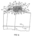
- FIG.1a wherein the inner member and corresponding conduit are on a centerline 33a, while the outer member and corresponding conduit are on a separate centerline 33b.
- the centerlines 33a and 33b when angulated, always intersect at a common center point 31 of the convex surface 28 and concave surface 32.
- the mid-portion 30 of the outer member 18 also defines a first radially inwardly opening groove 35 containing a first spring biased gas pressure energized, compression type gas seal ring assembly 37, a bearing surface 39 of which is spherically concave to closely conform to and slidably engage and seal against the convex surface 28.
- the inner member 16 defines a circumferentially extending, radially outwardly opening groove 34, which is preferably axially centered on the end portion 29 so as to open on an axial central part of the convex surface 28.
- the radial center of the groove 34 is located at the center point 31.
- the groove 34 carries an expansion type, spring biased, gas pressure energized gas seal ring assembly, generally designated 36, which will be explained in more detail later herein.
- the outer member 18 also includes a second end portion 38 which is of generally L-shaped radial cross-section, as viewed in FIGS. 1-1a .
- a radially outwardly extending leg 40 of the second end portion 38 attaches to a second end of the outer member mid-portion 30.
- An axially extending leg 42, of the second end portion 38 is radially outwardly spaced from the inner member 16 and connects, on one end thereof, to a radially outer end of the leg 40.
- a semi-circular spanner tool 25 (See FIG. 9 ) can be used.
- the tool 25 includes a pair of aligned handles 41 projecting outwardly from a semi-circular portion thereof at the ends of and essentially in the same plane as the semi-circular portion.
- the concave surface of the semi-circular portion is sized and shaped to conform to the periphery of the outer member mid portion 30 in the plane of a series of, preferably eight, radially outwardly opening and equally rotationally spaced apart blind holes 87 formed in the outer member 18 (See FIGS. 1 , 1a and 9 ).
- a thumb screw 43 located at the end of each of the handles 41 can be rotated to extend a pair of pins 45 radially inwardly toward one another from within opposite ends of a concave surface of the semi-circular portion of the tool. By reversing the rotation of the thumb screws 43, the corresponding pins 45 can be withdrawn back into the ends of the semi-circular portion.
- a third pin 47 projecting inwardly from the concave surface of the circular portion located rotationally mid-way between the retractable pins is fixed and need not be retractable. It is important that the pins 45, when extended, and the pin 47 match and align with three successive ones of the blind holes 87 formed in the outer member 18 when the tool is operatively positioned over the outer member in the plane of the blind holes.
- the tool 25 can be used to keep the member 18 from rotating as other members of the assembly 10 are rotated to remove them from the member 18, as will be explained later herein.
- the intermediate member 20 is disposed radially between the convex surface 28 and ring assembly 36, on its radially inner side, and the leg 42 of the outer member 18, on its radially outer side. A first axial end 44 of the member 20 abuts an end of the mid-portion 30 and the leg 40 of the outer member 18.
- the intermediate member 20 includes a spherically curved, concave, radially inwardly facing surface 46 which closely conforms to the outwardly facing convex surface 28 of the inner member 16 and, additionally, to a spherically crowned outwardly facing surface 48 of the ring assembly 36.
- the concave surface 46 ( FIG.1 ), of the intermediate member 20 cooperates with the concave surface 32 of the outer member 18 to oppose the convex surface 28 in a closely spaced manner, preferably a spacing of from about 0.005 to about 0.010 inch (0.127-0.254 mm) in the present example at typical operating temperature.
- the members 18 and 20 of the present example are separate and removably connected so that the coupling 10 can be disassembled and reassembled at the site of use without removal from the conduits 12 and 14, as when necessary to change seal ring assemblies contained therein. But, when the members 18 and 20 are connected, as shown, they cooperate as though they were a single, hollow annular outer member wherein their concave surfaces adjoin in a smooth and continuous manner.
- a second axial end portion of the leg 42 of the outer member 18, on a radially inwardly facing side thereof, and an opposing radially outwardly facing side of the intermediate member 20 are threaded and grooved in conformity with one another, as represented by dashed lines 50, so that they can be threadably secured to, and removed from, one another when necessary, such as when changing ring assemblies.
- a tool 53 having a semi-circular portion and a pair of handles 49 aligned with one another and projecting outwardly from the opposite ends of the semi-circular portion contains a series, preferably five, of equally rotationally spaced apart pins 57.
- the pins 57 project from a side of the tool 53 perpendicular to a plane containing the side.
- the pins 57 are adapted to align with and insert into blind holes 51 (See FIGS. 1 , 1a and 8 ) in a side of the intermediate member 20 which opposes a ring assembly 58.
- the tool 53 when operatively positioned, can be rotated to threadably attach the intermediate member 20 to the outer member 18 and to remove the former from the latter while the tool 25 is used to keep the member 18 from rotating with the member 20.
- the locking cap 22 includes an axially extending peripheral wall 52 and an adjacent cap end wall or shoulder 54 defining a circular central opening 55.
- the cap 22 is mounted over the end portion 24 of the inner member 16 before joining the conduit 12 to the end portion.
- the peripheral wall 52 contains a threaded and tapped, axially extending end portion which removably joins a conformingly threaded and tapped portion formed in a radially outer surface portion of the end portion 38 of the outer member 18, the adjoining threaded and grooved portions being represented by dashed lines 56.
- a third annular gas seal ring assembly, generally designated 58, is disposed around and radially between the convex surface 28 of the inner member 16 and a free end portion of the leg 42 of the outer member 18.
- the cap 22 when threadably tightened on the outer member 18, in the position as shown, compresses the seal ring assembly 58 between the cap shoulder 54 and a shoulder or ledge 60 on the leg 42 of the outer member 18.
- a conventional split steel retaining ring 62 is removably installed in a groove 64 ( FIG. 1 ) in an axial end portion of the periphery 52 of the cap 22, so as to interfere with and oppose a radially outer end portion of the leg 42 of the outer member 18.
- the retainer ring 62 prevents the loosening or unthreading of the cap 22 from the member 18 which could otherwise occur due to mechanical vibrations, thermal expansion or contraction and the like.
- the cap end wall 54 completes confinement of the end portion 38, intermediate member 20 and seal ring assembly 58 within the cap 22.
- the outer member 18, including the member 20, and the shoulder 54 of the cap 22 define a second radially inwardly opening groove for the ring assembly 58.
- the retaining ring 62 can be readily accessed for installation, removal and replacement as desired, through an annular, radially extending gap between a bore of the ring 62, as installed, and a radially inner end of the leg 40 at its joinder with an end of the mid-portion 30 of the outer member 18.
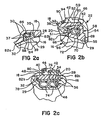
- the second seal ring assembly 58 comprises a seal ring (herein also referred to as ring 58) of generally C-shaped configuration, as viewed in cross section ( FIG.
- FIG. 2b in that it's hollow interior 66 ( FIG. 2b ) is surrounded by walls on three sides and is open on a fourth side, as at 68, facing an end surface of the intermediate member 20 (See FIG. 2b ).
- a compressible, canted spring 70 is installed through the opening 68 so as to be confined and compressed within the interior 66 so as to urge the three walls of the ring 58, as shown, to expand outwardly.
- a radially inwardly facing surface 72 of the ring 58 is spherically curved and is concave so as to closely conform to and slidably engage the convex surface 28 of the inner member 16.
- the cap 22 contains a series of, preferably eight, blind notches or slots 59 located in rotationally spaced apart relationship around an outer peripheral surface portion thereof.
- the slots 59 are rectangularly shaped and are open for entry from a side facing the end wall 54.
- a spanner wrench 61 having a semi-circular portion containing rotationally spaced apart rectangularly shaped pins 65 projecting from a concave side thereof and handles 63 projecting from opposite ends of the semi-circular portion, can be used to install and remove the cap 22 on and from the outer member 18.
- the pins 65 are aligned with and inserted into corresponding ones of the slots 59 and the handles can be rotated in the plane of the semi-circular portion to thread the cap 22 onto the outer member 18 or to remove the cap from the outer member following removal of the retainer ring 62. Again, during this procedure, the wrench 25 of FIG. 9 is used to stabilize the outer member 18 to prevent it from rotating as the cap 22 is rotated.
- the seal ring assembly 36 of the present example comprises a pair of canted springs 74 disposed adjacent one another in a base portion of the groove 34.
- the assembly 36 further includes an optional metal expansion ring 76 ( FIG. 1 ) disposed radially outwardly from the springs 74, axial end portions of which metal expansion ring are seated on axially and peripherally extending shoulders 78 (See FIG. 2c ) in the opposing sidewalls of the groove 34.
- the assembly 36 includes a suitable filled plastic seal ring 80, such as a PTFE plastic, having a radially outwardly facing convex, spherically crowned surface 48 as previously indicated. As best seen in detail in FIGS.
- the concave surfaces 32 and 46 of outer member 18 and the intermediate member 20, respectively are both very slightly spaced apart from the convex surface 28 of the inner member 16, as at gaps 82a, 82b and 82c (gap 82, generally), so that only the spherically curved seal ring surfaces 39, 48 and 72 of the first, second and third seal ring assemblies 37, 36 and 58, respectively, slidably engage opposing spherically curved, seal receiving surfaces.
- the first and second seal ring assemblies 37 and 58, respectively, are both of the compression type.
- the seal ring assembly 36 is of the expansion type.
- the first seal ring assembly 37 includes a suitable plastic seal ring 84, such as PTFE plastic, having the spherically concave surface 39 as previously explained.
- the ring 84 contains an L-shaped notch 86 ( FIG. 2a ) in a radially outer side surface portion in which a canted spring 88 is disposed in compression.
- the conforming threads and grooves 56 which adjoin the second end portion 38 of the outer member 18 with an interior threaded and grooved surface portion of the cap periphery 52, axially extend from the retainer ring groove 64 ( FIG.
- the peripheral wall 52 of the cap 22 defines an inwardly opening groove 92 ( FIG. 2b ) on and around an interior surface portion thereof.
- the ring 58 can be formed from PTFE plastic.
- a conventional O-ring 94 is disposed in compression in and around the groove 92.
- the seal ring 80 having its convex surface 48 slidably bearing against opposing portions of the concave surfaces 32 and/or 46, provides an effective seal to prevent most of the compressed air presented to the ring 80 from passing across it, to the right thereof, as viewed. Nevertheless, as to any amount of compressed air which crosses the ring 80, to the right thereof as viewed, into the gap 82c, such amount will seep through the air gap 96 (See FIG.
- the O-ring 94 provides a fourth and final barrier to the leakage of compressed air from the coupling 10. It is believed that, under operating conditions, the air pressure in the gaps 82c and 96 will be in the neighborhood of one-half the air pressure in the gap 82a.
- the area of the bearing surface 72 of the ring 58 should be larger, preferably, about twice the area of the bearing surface 39 of the ring 84. Note the larger size of the ring 58 as compared with the ring 84 in FIG. 1 . In other words, the larger area of bearing surface 72 will enable seal ring assembly 58 to apply a load to the inner member that is approximately equal to the loading applied to the inner member by the smaller surface area of bearing surface 39 of seal ring assembly 37.
- the need for a larger surface area in the "downstream" seal ring assembly 58 is a result of its seeing less pressure from any gas located in gap 82c since said gas will have experienced a pressure drop prior to reaching gap 82c.
- the overall magnitude of loading in the coupling is also preferably balanced.
- Seal ring assemblies 37 and 58 together apply an inwardly-directed compression force on the inner member 16. This force is preferably substantially equal in magnitude to, and effectively counterbalanced by, the outwardly-directed expansion force applied to the outer member 18 by seal ring 80.
- the coupling provide a balance in the total magnitude of the forces exerted by the seal ring assemblies
- the locations in which the seal ring assemblies exert their pressure is also balanced along the axial length of the coupling. This is achieved by virtue of the placement of the compression-type ring assemblies 37 and 58 on either side of the expansion-type seal ring 80.
- assemblies 37 and 58 preferably apply approximately equal loads at locations that are equidistant from the center of the spherical portion of the inner member.
- seal ring 80 is located at the center of the spherical portion of the inner member. In this manner, inward force applied to the inner member by structure associated with seal ring 80 will be directed toward the center of the inner member's spherical portion.
- the end result of having a balance in the total forces applied by the seals and an axial balance in their points of application is that overall joint load is evenly distributed and seal wear is both minimized and evenly distributed among the seals. Furthermore, the distribution and balance of the forces applied by the seals enables smooth and controlled angulation (movement of the coupling's inner member relative to the coupling's outer member) without localized points of high stress or resistance to movement.
- the coupling 10 of the present example is recommended for use in gaseous environments wherein the gas temperature typically does not exceed about 600°F (316°C) and wherein the gas pressure is typically not in excess of about 200 psi (13.8 bar). As used herein, this temperature and pressure is considered the dividing line between high and low temperature environments and between high and low pressure environments, respectively.
- the convex and concave surfaces 28 and 32, respectively, are thus operatively movable relative to one another as a result of mechanical vibrations or otherwise about the common center point 31 of FIG. 1 .
- the center of the outwardly opening groove 34 is also located at the center point 31.
- the inwardly opening groove 35 and the groove containing the ring assembly 58 are parallel, spaced apart and in registry with one another with their common center line, as at 33 in FIG. 1 , always intersecting the center point 31 for all operative orientations of the convex and concave surfaces 28 and 32 relative to one another.
- a flexible coupling generally designated 100, including, as before, a hollow, annular inner member, generally designated 102, a hollow annular outer member, generally designated 104 (which includes an annular intermediate member 106) and an annular end cap, generally designated 108, defining a peripheral skirt 110 and an end wall 112 containing a circular central opening 114.
- the inner member 102 defines a radially outwardly facing, spherically curved, convex seal receiving surface 116 and the outer member 104 (together with the intermediate member 106 in combination) define a radially inwardly facing, spherically curved, concave seal receiving surface 118.
- the surfaces 116 and 118 closely conform to each other in curvature and are closely spaced apart as indicated by gaps 120a, b and c (120 generally) in FIGS. 4a , b and c.
- the convex surface 116 occupies a first end portion of the inner member 102 while a second end portion 120 of the inner member is adapted for connection to a first conduit as by welding or other suitable means.
- the inner member 102 defines first circular openings 122 and 124 which are parallel with and opposite one another across the convex surface 116.
- the radial centers 126, 128 of the openings 122 and 124, respectively, are joined by a centerline 130 which extends through a center point 132 of the convex surface 116.
- the center point 132 is also the center of the concave surface 118 for all operative orientations of the two surfaces under and over one another.
- the inner member 102 defines a radially outwardly opening groove 134 containing an expansion type ring assembly, generally designated 136.
- the radial center of the groove 134 is also at the center 132 of the inner and outer members 102 and 104.
- the assembly 136 includes a pair of expansion springs 138 disposed in a base of the groove 134, a pair of expansion rings 140 and a pair of seal rings 142 which project out of the groove 134 into gas sealing engagement with the concave surface 118 of the outer member 104, including, in combination, the intermediate member 106.
- the gas sealing or bearing surfaces of the rings 142 are spherically crowned in conformity with the concave surface 118.
- the concave surface 118 of the outer member 104 is also centered on the point 132 so that the convex surface 116 and concave surface 118 are always centered on the same center point 132, regardless of their movement and orientation relative to one another.
- the outer member 104 defines a first inwardly opening groove 144 in which is disposed a first compression type seal ring assembly, generally designated 146.
- the assembly 146 includes a first compression ring 148 which is biased radially inwardly against the convex surface 116 by a spring 150.
- the ring 148 includes a concave bearing surface which engages the convex surface 116.
- the assembly 146 also includes a second seal ring 152 which has a concave bearing surface which bears upon the convex surface 116.
- the cap 108 is mounted over the convex surface 116 so that the end wall 112 encloses an end of the outer member 104 and a corresponding end of the intermediate member 106 to define a second inwardly opening ring assembly groove 154.
- the end wall 112 contains a circular central opening 114 through which the inner member 104 extends.
- the groove 154 contains a second compression type spring biased and gas pressure energized seal ring assembly, generally designated 156.
- the assembly 156 includes a first spring biased seal ring 158, a compression ring 160 and a spring 162.
- the assembly 156 also includes a second seal ring 164 which projects from the groove 154 and fits against a shoulder or ledge 166 formed in a radially inwardly facing side of an end portion of the outer member 104. See FIG. 4b .
- the groove 154 is thus defined by the cap end wall 112, an end portion of the outer member 104, an end of the intermediate member 106 and the convex surface 116.
- a peripheral slot 168 is formed in and around an interior surface portion of the cap periphery 110 in which is disposed a metallic non-gas pressure energized seal ring 170.
- the cap 108 may be threadably secured to the outer member 104 and, likewise, the member 104 to the interior member 106, the same as in the previous example.
- a retainer ring 174 is removably mounted in a groove located on an interior end portion of the cap periphery 110 of the cap 108.
- the seal ring assemblies 136, 146 and 156 of the present example are adapted to function typically at temperatures up to about 1200°F and at gas pressures up to about 1200psi.
- the seal rings 148, 152, 142, 158 and 164 can be constructed of materials such as nickel alloys, corrosion resistant steel, inconel and the like.
- FIG. 4d shows the same ring assembly as at 136 in FIG. 4c , except that a pair of conventional Marcel springs 139 is substituted in place of canted springs 138.
- a flexible coupling for transferring a compressed gas between a pair of conduits 178, 180.
- a body of the coupling 176 includes essentially the same three component parts as in the previous examples, namely, a hollow annular inner member, generally designated 182, defining a radially outwardly facing, spherically curved, convex, seal receiving surface 184 and a radially outwardly opening ring assembly retainer groove 186.
- the coupling 176 also includes a hollow annular outer member, generally designated 188, which also includes a threadably interconnected annular intermediate member 190, which cooperate with each other to define a radially inwardly facing, spherically curved, concave, seal receiving surface 192.
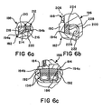
- the convex and concave surfaces 184 and 192 closely conform in curvature and are closely spaced apart in general opposition to each other as indicated by small gaps 194a, b and c (194 generally) in FIGS. 6a, b and c .
- the gap 194 between the convex and concave surfaces 184 and 192 should preferably, be from about 0.005 to 0.010 inches (0.127-0.254 mm) in width.
- the coupling 176 includes a locking or end cap, generally designated 196, defining a circular central opening 198 in an end wall 200 which permits the end cap to mount over the inner member 182.
- the cap 196 also contains a peripheral skirt 202 which can be threadably interconnected over and to the outer member 188, the threading being represented by dashed lines 204 in FIG. 5 .
- the outer member 188 can also be threadably interconnected with the intermediate member 190 as represented by dashed lines 206 in FIG. 5 .
- the convex surface 184 and the concave surface 192 are movable relative to one another about a common center point 208.
- the groove 186 includes the same ring assembly 136 as is disposed in the groove 134 of the previous example.
- the outer member 188 defines a first inwardly opening seal ring assembly retaining groove 210 containing a first compression type, gas pressure energized gas seal ring assembly 212.
- the assembly 212 includes a gas pressure energized seal ring 214 of a C-shaped cross-section next to a metal seal ring 216. As shown in FIG. 6a , high pressure gas entering the gap 194a enters the ring 214 to expand the same and force the seal ring 216 against an opposite wall 218 of the groove 210.
- the seal ring 216 includes spherically curved, concave bearing surface 220 which is also forced into tighter engagement with the opposing convex surface of the inner member 182 as the pressure energized ring 214 expands.
- the groove 222 is thus bounded by the cap end wall 200, the convex surface 184 ( FIG. 5 ) of the inner member 182 and an end wall 224 ( FIG. 6b ) of the intermediate member 190.
- High pressure gas entering the groove 222 through the gap 194c causes a gas pressure energized ring 226 of C-shaped cross section to open to force a compression type seal ring 228 against the end wall 224 to prevent gas from escaping between opposing surfaces of the end wall 224 and the ring 228.
- a metallic non-pressure energized seal ring 230 is captured in an annular groove formed in an interior peripheral wall portion of the cap skirt 202. See FIG. 5 .
- a retainer ring 232 is removably positioned in a radially inwardly opening groove in an end portion of the skirt 202.
- the seal ring assemblies 136, 212 and 226, 228 of the present example are also adapted for use in temperatures typically up to about 1200°F (648.9°C) and gas pressure, up to about 1200 psi (82.70 bar).
- the maximum angle between the center line 33a of the member 16 and conduit 12, on one hand, and the intersecting center line 33b of the member 18 and conduit 14, on the other hand can be at least five degrees in any direction.
- the ring assemblies 36, 37 and 58 and the O-ring 94 can be replaced without having to remove the coupling 10 from the conduits 12 and 14 according to the following procedure:
- the retaining ring 62 is removed from the cap groove 64 and allowed to hang loosely, for the time being, around member 18 or the adjoining conduit 14.
- the cap 22 is rotated to threadably disconnect it from the member 18 while the spanner wrench 25 of FIG. 9 , with its retractable pins 45 extending so that the pins 45 and 47 are inserted into aligned ones of the blind holes 87 of the member 18, is used to hold the member 18 stationary.
- the cap 22 is removed from around the convex surface, to the right as viewed, and hung loosely around the conduit 12 so as to be out of the way.
- the old O-ring 94 can be removed from the cap groove 92 ( FIG. 2b ) and the now exposed old ring assembly 58 can be pulled away from the convex surface 28 toward the conduit 12.
- the old O-ring 94 and ring assembly 58 can each be cut into two pieces for removal and discarding.
- the member 20 is rotated to threadably disconnect it from the leg 38 of the member 18. Upon disconnection, the member 20 is also removed from around the convex surface 28, to the right as viewed, and placed loosely over the conduit 12, to the left of and next to the cap 22.
- the members 16 and 18 are separated by pulling them apart, to the right and left respectively, as viewed.
- the ring assembly 37 can be removed from the groove 35 and discarded.
- the now exposed ring assembly 36 can be dug, pried or otherwise removed from the groove 36 and, if necessary, cut into two pieces and discarded.
- the new O-ring 94 is applied over the member 16 and is installed in the cap groove 90. See FIG. 2b .
- the new ring 58, without spring 66, is then introduced into the gap between the members 16 and 18.
- the ring 58, so introduced, can be tilted so that a semi-circular portion thereof can be slid along the outwardly expanding portion of the convex surface 28 until it drops, in a tilted manner, into the now empty central ring groove 34.
- the remaining semi-circular portion of the ring 58 is moved over an opposing portion of the convex surface 28 until the ring is fully and loosely disposed in the groove 34. Then, by pushing a lower portion of the ring 58 upwardly into a corresponding lower portion of the groove 34 so that an upper portion of the ring projects out of an upper portion of the groove, the upper ring portion can be tilted, to the right as viewed, over the inwardly contracting portion of the convex surface 28.
- the upper ring portion is permitted to drop against the convex surface 28 to allow the lower ring portion to project out of the lower portion of the groove 34 so that the lower ring portion can be moved along the opposing inwardly contracting portion of the surface 28 for placement of the ring loosely on the conduit 12, to the left of the member 20, as viewed.
- the spring 66 is now introduced into the gap between the members 16 and 18 and is moved over the convex surface 28 to a position next to and on the left side of the ring 58.
- the ring assembly 36 is introduced into the gap between the members 16 and 18 and placed in the groove 34 with the springs 74 being placed first, the expansion ring 76, if used, next, followed by the seal ring 80.
- the ring 76 being a cut ring, permits opening of the ring as necessary to apply it over the convex surface 28 into the groove 34.
- the seal ring 80 if cut, can likewise, be opened to facilitate placement in the groove 34. If the ring 80 is not cut or split, since it is constructed of a flexible plastic, it can be stretched sufficiently to slide over the surface 28 into the groove 34. If the ring 80 is an uncut plastic ring, the expansion ring 76 may or may not be used.
- the ring assembly 37 is installed in the groove 35, whereupon the members 16 and 18 are partially, but almost completely, rejoined by hand to place the ring assembly 37 over and into engagement with the surface 28.
- the intermediate member 20 is lifted off of the conduit 12 and moved to the left, as viewed, while the ring 58, followed by the spring 66, are separately passed through the intermediate member, to be placed on the right side thereof, as viewed, with the spring still to the left of the ring.
- the spanner wrench 53 of FIG. 8 is used to rejoin the intermediate member 20 to the leg 38 of the member 18 while the spanner wrench 25 of FIG. 9 is used to hold the outer member stationary. Rejoinder of the member 20 with the member 18 should complete any small misjoinder between the members 16 and 18 that may have existed following the fourth step.
- the cap 22 is rotated over and rejoined to the outer member 18, while the spanner wrench 25 of FIG. 9 is used to hold the outer member stationary, thus bringing the ring 58 into proper position under the outer leg 42 and against the shoulder 60 ( FIG. 2b ).
- the retainer ring 62 is reinstalled in the cap groove 64.
- the ring assemblies 36, 37 and 58 and the O-ring 94 can be removed and replaced without the necessity of removing the coupling from connection to the conduits 12 and 14 for being disassembled and reassembled at a remote work station.
- the retainer ring 62 now prevents the cap 22 from decoupling from the outer member 18 which might otherwise occur due to vibration, thermal expansion or contraction or the like during in-service operation of assembly 10.
- the present invention is capable of being exploited in any situation where a flexible joint is desired to connect together multiple conduits.
Landscapes
- Engineering & Computer Science (AREA)
- General Engineering & Computer Science (AREA)
- Mechanical Engineering (AREA)
- Chemical & Material Sciences (AREA)
- Combustion & Propulsion (AREA)
- Joints Allowing Movement (AREA)
- Quick-Acting Or Multi-Walled Pipe Joints (AREA)
Claims (32)
- Flexible Kopplung (10, 100, 176) zum Transferieren eines unter Druck befindlichen Gases zwischen einer ersten Leitung (12) und einer zweiten Leitung (14), umfassend:ein hohles ringförmiges Innenteil (16), das eine sphärisch gekrümmte, konvexe Dichtungsaufnahmeoberfläche (28) und eine ringförmige Dichtungsringanordnung-Zurückhaltungskerbe (34), welche sich nach außen auf der konvexen Oberfläche öffnet definiert;ein hohles ringförmiges Außenteil (18), das über dem Innenteil befestigt ist und eine sphärische gekrümmte, konkave Dichtungsaufnahmeoberfläche (32) definiert, welche zu der konvexen Oberfläche passt und gegenüber dieser beabstandet ist, wobei die konvexe Oberfläche und die konkave Oberfläche relativ zueinander um einen gemeinsamen Zentralpunkt beweglich sind, wobei das Außenteil weiterhin eine erste ringförmige Dichtungsringanordnung-Zurückhaltekerbe (35) definiert, die sich nach innen auf der konkaven Oberfläche entgegengesetzt zu der konvexen Oberfläche öffnet;eine ringförmige Endkappe (22), die mit dem Außenteil verbunden ist und eine Endwand hat, die ein Ende des Außenteils umgibt und die in Kombination mit dem Außenteil eine zweite ringförmige Dichtungsringanordnung-Zurückhaltungskerbe definiert, welche sich nach innen entgegengesetzt zu der konvexen Oberfläche öffnet;eine Serie von Dichtungsringanordnungen (36, 37, 58), wobei jeweils eine andere der Anordnungen in jeder der Kerben angeordnet ist, wobei jede der Anordnungen mindestens einen Dichtungsring beinhaltet, der aus einer korrespondierenden Kerbe hervorsteht und der eine Lageroberfläche beinhaltet, die passt zu und eingreift mit einer Gegenüberliegenden der Dichtungsaufnahmeoberflächen; undwobei sich die nach außen auf der konvexen Oberfläche öffnende Dichtungsringanordnung-Zurückhaltekerbe zwischen der ersten und der zweiten ringförmigen Dichtungsringanordnung-Zurückhaltekerbe befindet, die sich nach innen öffnet.
- Kopplung (10, 100, 176) nach Anspruch 1, wobei das Innenteil (16) einen ersten offenen Endabschnitt (24), der für Anbringen an der ersten Leitung (12) eingerichtet ist, und einen zweiten offenen Endabschnitt (29), der die konvexe Oberfläche definiert, umfasst, wobei das Außenteil (18) einen ersten offenen Endabschnitt (26), der eingerichtet ist, um an der zweiten Leitung (14) angebracht zu werden, und einen zweiten offenen Endabschnitt (30), der die konkave Oberfläche definiert, umfasst.
- Kopplung (10, 100, 176) nach Anspruch 1, wobei das Außenteil (18) lösbar über dem Innenteil (16) befestigt ist.
- Kopplung (10, 100, 176) nach Anspruch 1, wobei die Endkappe (22) eine Endwand (54) beinhaltet, die eine kreisförmige Zentralöffnung definiert, wobei die Endkappe lösbar über dem Innenteil (16) befestigt ist, und lösbar mit dem Außenteil (18) verbunden ist.
- Kopplung (10, 100, 176) nach Anspruch 1, wobei das Außenteil (18) einen ersten Teil und einen zweiten Teil, der von dem ersten Teil getrennt ist und damit lösbar verbunden ist, umfasst, wobei der erste Teil und der zweite Teil in Kombination die konkave Oberfläche (32) definieren, wenn sie operativ verbunden sind.
- Kopplung (10, 100, 176) nach Anspruch 1, wobei die konvexe Oberfläche (28) einen Abschnitt einer Kugel mit offenen gegenüberliegenden Enden, die im Wesentlichen parallel zueinander sind, umfasst, wobei die sich nach außen öffnende Kerbe (34) auf dem Zentralpunkt zentriert ist und derart positioniert ist, dass sie im Wesentlichen parallel und axial äquidistant zu den offenen gegenüberliegenden Enden ist.
- Kopplung (10, 100, 176) nach Anspruch 1, wobei die Endkappe (22) lösbar mittels Gewinde mit dem äußeren Teil (18) verbunden ist.
- Kopplung (10, 100, 176) nach Anspruch 1, weiterhin einen Zurückhaltering (62) umfassend, der mit einem offenen Endabschnitt der Endkappe (22) lösbar verbunden ist, um Trennung des Außenteils (18) von der Endkappe zu verhindern.
- Kopplung (10, 100, 176) nach Anspruch 1, wobei die Endkappe (22) eine Umfangswand (52) beinhaltet, die im Inneren mit Gewinde versehen ist, wobei ein äußerer Umfangsoberflächenabschnitt von dem Außenteil (18) außen mit Gewinde versehen ist, wobei die Umfangswand und der Umfangsoberflächenabschnitt lösbar über ein Gewinde miteinander verbunden sind.
- Kopplung (10, 100, 176) nach Anspruch 1, weiterhin einen O-Ring (94) umfassend, der zwischen der Endkappe (22) und dem Außenteil (18) angeordnet ist.
- Kopplung (10, 100, 176) nach Anspruch 1, wobei die sich nach außen öffnende Kerbe (34) auf dem Zentralpunkt zentriert ist und wobei die erste (35) und zweite Kerbe parallel zueinander sind und miteinander eingreifen und eine gemeinsame Zentrallinie haben, die den Zentralpunkt in allen operativen Orientierungen der konvexen Oberfläche (28) relativ zu der konkaven Oberfläche (32) schneidet.
- Kopplung (10, 100, 176) nach Anspruch 1, wobei eine der in der ersten Kerbe (35) angeordneten Anordnungen (37) umfasst:einen ersten Gasdichtungsring (84), der eine ringförmige Einbuchtung (86) in einem axialen Seitenabschnitt mit hohem Gasdruck und in einem äußeren Umfangsoberflächenabschnitt von dieser definiert; undeine erste radial komprimierte und expandierbar gekippte Feder (88), die in der Ausbuchtung angeordnet ist, zum Bereitstellen einer Minimaldichtung auf einer Seite mit geringem Gasdruck des Dichtungsrings gegen eine gegenüberliegende Seitenwand der ersten Kerbe, wobei die Feder auch eine Minimaldichtung der Lageroberfläche des ersten Dichtungsrings auf der konvexen Oberfläche (28) bereitstellt.
- Kopplung (10, 100, 176) nach Anspruch 1, wobei das Außenteil (18) einen ersten Teil und einen zweiten Teil umfasst, die zusammenwirken, um die konkave Oberfläche (32) auszubilden, wobei der zweite Teil zwischen der konvexen Oberfläche und einem Fuß (42) des Außenteils angeordnet ist, wobei das zweite Teil lösbar und mittels Gewinde mit einem Innenoberflächenabschnitt des Fußes verbunden ist, wobei die Kappe (22) lösbar und mittels Gewinde mit einem Außenoberflächenabschnitt des Fußes verbunden ist.
- Kopplung (10, 100, 176) nach Anspruch 1, wobei die konvexe Oberfläche (28) einen Abschnitt einer Kugel ausbildet, die gegenüberliegende offene Enden hat, die parallel zueinander sind, wobei die sich nach außen öffnende Kerbe (34) auf dem Zentralpunkt zentriert ist und parallel und äquidistant zu den offenen Enden ist.
- Kopplung (10, 100, 176) nach Anspruch 1, wobei die Dichtungsringanordnungen (136, 146, 156) jeweils mindestens einen mit einer Feder vorgespannten, unter Gasdruck energetisierten Gasdichtungsring umfasst.
- Kopplung (10, 100, 176) nach Anspruch 1, wobei eine der Anordnungen (37), die in der ersten Kerbe (35) angeordnet ist, einen ersten, unter Gasdruck energetisierten Gasdichtungsring (84) umfasst, der eine sich nach außen erstreckende Ausbuchtung (86) in einem Außenseitenabschnitt davon mit hohem Gasdruck und eine ringförmige gekippte Feder (88), die in der Ausbuchtung zum Vorspannen des ersten Rings in eine Gasdichtungsposition gegen einen Seitenabschnitt der ersten Kerbe mit geringem Druck und gegen die konvexe Oberfläche angeordnet ist, definiert.
- Kopplung (10, 100, 176) nach Anspruch 1, wobei die sich nach außen öffnende Kerbe (34) auf der konvexen Oberfläche sich ringförmig erstreckende Leisten auf gegenüberliegenden Seiten von dieser definiert, wobei eine der Anordnungen (36), die in der sich nach außen öffnenden Kerbe angeordnet ist, ein Paar gekippter Vorspannfedern, die nebeneinander in einer Basis von der sich nach außen öffnenden Kerbe angeordnet sind, und einen zweiten PTFE-Kunststoffgasdichtungsring mit einer sphärischen oben befindlichen konvexen Lageroberfläche, die zu der konkaven Oberfläche passt und mit dieser eingreift, umfasst, wobei der zweite Ring in der sich nach außen öffnenden Kerbe auf den Leisten gelagert ist.
- Kopplung (10, 100, 176) nach Anspruch 1, wobei eine der Dichtungsringanordnungen, die in der zweiten Kerbe (222) angeordnet ist, einen dritten unter Gasdruck energetisierten Gasdichtungsring (226) mit einem im Wesentlichen C-förmigen radialen Querschnitt umfasst, der ein hohles ringförmiges Inneres definiert, welches eine Öffnung hat, die einem radialen inneren Endabschnitt von dem Außenteil zugewandt ist, und weiterhin eine in dem Inneren angeordnete gekippte Vorspannfeder umfasst, um drei Seiten des dritten Rings in Gas-dichtendes Eingreifen mit gegenüberliegenden Seiten des Außenteils, der konvexen Oberfläche und der Endkappe zu drängen, wobei das Außenteil eine Kante definiert, gegen die der dritte Dichtungsring gelagert ist, um einen Gasleckschlitz zwischen einer Seite des Außenteils und einer gegenüberliegenden Seite des dritten Rings, der die Öffnung beinhaltet, bereitzustellen, wobei der Gasleckschlitz in Kommunikation mit einem Raum zwischen der konvexen Oberfläche und der konkaven Oberfläche ist, durch welchen ein unter Druck stehendes Gas eingeführt werden kann, um den dritten Ring mittels Gas zu energetisieren.
- Kopplung (10, 100, 176) nach Anspruch 1, wobei gegenüberliegende Abschnitte der konvexen Oberfläche (28) und der konkaven Oberfläche (32) gegeneinander durch die Dichtungsringanordnungen um eine Entfernung in dem Bereich von etwa 0,127 mm (0,005 inch) bis ungefähr 0,254 mm (0,010 inch) beabstandet sind.
- Kopplung (10, 100, 176) nach Anspruch 1, wobei eine Fläche der Lageroberfläche des Dichtungsrings, der in der zweiten Kerbe beinhaltet ist, größer als eine Fläche der Lageroberfläche des Dichtungsrings, der in der ersten Kerbe (35) beinhaltet ist, ist.
- Kopplung (10, 100, 176) nach Anspruch 1, wobei die sich nach außen öffnende Kerbe (34) auf dem Zentralpunkt zentriert ist, wobei die erste und zweite Kerbe parallel zueinander und in Eingriff miteinander sind und eine gemeinsame Zentrallinie haben, die den Zentralpunkt in allen operativen Orientierungen der konvexen Oberfläche (28) relativ zu der konkaven Oberfläche (32) schneidet.
- Kopplung (10, 100, 176) nach Anspruch 1, wobei eine der Anordnungen (58), die in der zweiten Kerbe angeordnet ist, ein drittes Paar Dichtungsringe, einen Kompressionsring, der über einem von dem dritten Paar Ringe befestigt ist, der auf einer Seite mit niedrigem Druck der zweiten Kerbe befindlich ist, und eine Vorspannfeder, die sich zwischen dem Kompressionsring und einer Basis der zweiten Kerbe befindet, umfasst, wobei beide von dem dritten Paar Dichtungsringe in Kombination eine einzelne durchgängige konkave Lageroberfläche ausbilden, die zu der konvexen Oberfläche (28) passt und mit dieser eingreift.
- Kopplung (10, 100, 176) nach Anspruch 1, wobei eine der Anordnungen (212), die in der ersten Kerbe (210) angeordnet ist, einen C-Ring, der auf einer Seite mit hohem Druck der zweiten Kerbe angeordnet ist, und einen ersten Dichtungsring, der neben dem C-Ring auf einer Seite mit niedrigem Druck der zweiten Kerbe angeordnet ist, umfasst, wobei sich der C-Ring hin zu einer Seite mit hohem Druck der zweiten Kerbe öffnet.
- Kopplung (10, 100, 176) nach Anspruch 1, wobei eine der Anordnungen, die in der zweiten Kerbe (222) angeordnet ist, einen dritten Dichtungsring (226), der auf einer Seite mit hohem Druck der zweiten Kerbe angeordnet ist, und einen C-Ring, der auf einer Seite mit niedrigem Druck der zweiten Kerbe angeordnet ist, umfasst, wobei sich der C-Ring hin zu dem dritten Dichtungsring öffnet.
- Kopplung (10, 100, 176) nach Anspruch 1, wobei eine der Anordnungen (37), die in der ersten Kerbe (35) angeordnet ist, die ein erstes Paar Dichtungsringe und eine Vorspannfeder umfasst, die sich zwischen einem von dem ersten Paar Ringen, das sich auf einer Seite mit hohem Druck der ersten Kerbe befindet und einer Basis der ersten Kerbe befindet.
- Kopplung (10, 100, 176) nach Anspruch 1, wobei eine der Anordnungen (36), die in der sich nach außen öffnenden Kerbe (34) angeordnet ist, ein Paar Vorspannfedern, das in einer Basis der sich nach außen öffnenden Kerbe angeordnet ist, ein Paar Expansionsringe, das über den Vorspannfedern angeordnet ist, und ein zweites Paar Dichtungsringe, das über den Expansionsringen angeordnet ist, umfasst, wobei beide von dem zweiten Paar Dichtungsringe eine oben befindliche Dichtungsoberfläche haben, die in Kombination eine einzelne durchgängige konvexe Oberfläche ausbilden, die passt zu und eingreift mit der Oberfläche.
- Kopplung (10, 100, 176) nach Anspruch 5, wobei das zweite Teil zwischen der konvexen Oberfläche (28) und einem axialen Endabschnitt des ersten Teils angeordnet ist, wobei gegenüberliegende Oberflächenabschnitte des ersten Teils und des zweiten Teils übereinstimmend mit Gewinde versehen sind, sodass sie lösbar mittels Gewinde verbunden sind.
- Kopplung (10, 100, 176) nach Anspruch 5, wobei das erste Teil, das zweite Teil und die Endkappe zusammenwirken, und die zweite Kerbe zu definieren.
- Kopplung (10, 100, 176) nach Anspruch 1, wobei der Dichtungsring, der sich in der nach außen öffnenden Dichtungsringanordnung-Zurückhaltekerbe (34) befindet, ein erster Dichtungsring ist, wobei der erste Dichtungsring eine nach außen gerichtete Kraft auf das Außenteil (18) anwendet, wobei der Dichtungsring, der sich in der ersten ringförmigen Dichtungsringanordnung-Zurückhaltekerbe (35) befindet, die sich nach innen öffnet, ein zweiter Dichtungsring ist, wobei der Dichtungsring, der sich in der zweiten nach innen öffnenden ringförmigen Dichtungsringanordnung-Zurückhaltekerbe befindet, ein dritter Dichtungsring ist, wobei der zweite und dritte Dichtungsring eine nach innen gerichtete Kraft auf das Innenteil (16) anwenden, wobei sich der erste Dichtungsring zwischen dem zweiten und dritten Dichtungsring befindet und wobei die nach außen gerichtete Kraft im Wesentlichen durch die nach innen gerichtete Kraft aufgewogen wird.
- Kopplung (10, 100, 176) nach Anspruch 6, wobei die konkave Oberfläche (32) einen Abschnitt einer Kugel mit offenen gegenüberliegenden Enden umfasst, wobei axiale Zentralschichten der ersten Kerbe und der zweiten Kerbe parallel zueinander sind und wobei, wenn die konvexe Oberfläche (28) und die konkave Oberfläche (32) in einer Position relativ zueinander sind, in der alle Kerben im Wesentlichen parallel zueinander sind, die sich nach außen öffnende Kerbe zwischenliegend ist zu und äquidistant ist zu der ersten Kerbe und der zweiten Kerbe ist.
- Kopplung (10, 100, 176) nach Anspruch 14, wobei die erste Kerbe (35) und die zweite Kerbe parallel zueinander sind und in Eingriff miteinander sind und eine gemeinsame Zentrallinie haben, die den Zentralpunkt schneidet.
- Kopplung (10, 100, 176) nach Anspruch 20, wobei die Lageroberfläche-Fläche des Dichtungsrings, der in der zweiten Kerbe beinhaltet ist, ungefähr zweimal die Oberflächen-Fläche des in der ersten Kerbe (35) beinhalteten Dichtungsrings hat.
Applications Claiming Priority (2)
| Application Number | Priority Date | Filing Date | Title |
|---|---|---|---|
| US10/456,075 US6880863B2 (en) | 2003-06-06 | 2003-06-06 | Flexible coupling for gas conduits |
| PCT/US2004/016337 WO2004111512A2 (en) | 2003-06-06 | 2004-05-25 | Flexible coupling for gas conduits |
Publications (3)
| Publication Number | Publication Date |
|---|---|
| EP1631764A2 EP1631764A2 (de) | 2006-03-08 |
| EP1631764A4 EP1631764A4 (de) | 2010-12-01 |
| EP1631764B1 true EP1631764B1 (de) | 2013-03-27 |
Family
ID=33490075
Family Applications (1)
| Application Number | Title | Priority Date | Filing Date |
|---|---|---|---|
| EP04753209A Expired - Lifetime EP1631764B1 (de) | 2003-06-06 | 2004-05-25 | Flexible gasleitungskupplung |
Country Status (3)
| Country | Link |
|---|---|
| US (1) | US6880863B2 (de) |
| EP (1) | EP1631764B1 (de) |
| WO (1) | WO2004111512A2 (de) |
Families Citing this family (14)
| Publication number | Priority date | Publication date | Assignee | Title |
|---|---|---|---|---|
| US6968832B1 (en) * | 2004-05-06 | 2005-11-29 | International Engine Intellectual Property Company, Llc | Connection system for exhaust gas recirculation (EGR) |
| DE102006029705B4 (de) * | 2006-06-28 | 2009-08-20 | Airbus Deutschland Gmbh | Rohrverbindung und Rohrverbindungssystem mit derartigen Rohrverbindungen |
| AU2008202426B2 (en) * | 2007-06-01 | 2012-10-11 | Plastec Australia Pty Ltd | A coupler for coupling conduits in flow communication with each other |
| US7883094B2 (en) * | 2008-08-19 | 2011-02-08 | Delaware Capital Formation, Inc. | Offset stacked sealing system |
| US8231144B2 (en) * | 2009-06-23 | 2012-07-31 | Honeywell International, Inc. | Joint assemblies |
| FR3011059B1 (fr) * | 2013-09-24 | 2016-05-27 | Snecma | Dispositif de raccord hydraulique et systeme de transfert de fluide utilisant ce dispositif |
| US10132437B2 (en) * | 2014-12-05 | 2018-11-20 | Oetiker Ny, Inc. | Fluid connector with a swivel body |
| US10625871B1 (en) * | 2015-08-24 | 2020-04-21 | Roller Bearing Company Of America, Inc. | Dynamic movement tube connection system |
| DE202016005439U1 (de) * | 2016-09-07 | 2017-09-08 | Bernd Stängle | Gelenkleitung |
| US10422279B2 (en) | 2016-11-04 | 2019-09-24 | Senior Ip Gmbh | Spherical compensator junction assembly for high pressure ducting system |
| US20200347970A1 (en) * | 2019-04-30 | 2020-11-05 | Roller Bearing Company Of America, Inc. | Low profile flexible coupling and tool for assembling flexible couplings |
| US11053973B2 (en) * | 2019-11-08 | 2021-07-06 | Flowserve Management Company | Dry running ball joint mechanical seal |
| US12158226B2 (en) | 2020-05-15 | 2024-12-03 | Roller Bearing Company Of America, Inc. | Flexible alignment sealing coupling |
| CN115059800A (zh) * | 2022-07-27 | 2022-09-16 | 苏州谱测光电科技有限公司 | 一种具有预警外力破坏功能的管道防护装置 |
Family Cites Families (30)
| Publication number | Priority date | Publication date | Assignee | Title |
|---|---|---|---|---|
| US203611A (en) * | 1878-05-14 | Improvement in car-heating apparatus | ||
| US2220120A (en) * | 1938-02-17 | 1940-11-05 | Benjamin G Plummer | Universal joint for tubing |
| US2421691A (en) * | 1943-09-04 | 1947-06-03 | Lockheed Aircraft Corp | Universal joint |
| US2417491A (en) * | 1944-09-09 | 1947-03-18 | Glenn L Martin Co | Universal fluid joint |
| US3479061A (en) * | 1966-09-23 | 1969-11-18 | Arthur L Smookler | Partially balanced flexible pipe joint |
| DE1945523A1 (de) * | 1969-09-09 | 1971-03-11 | Martin Herter | Kugelgelenkrohrverbindung |
| US3666049A (en) | 1970-10-12 | 1972-05-30 | Kern Roll And Rubber Co | Expander roll assembly with oil-mist lubrication |
| US3746372A (en) * | 1971-05-27 | 1973-07-17 | Vetco Offshore Ind Inc | Flexible pipe joints |
| US3967829A (en) | 1973-03-09 | 1976-07-06 | Rogers-Dierks, Inc. | Seal ring |
| US3929355A (en) * | 1974-04-04 | 1975-12-30 | Anatoly Emelyanovich Sljusar | Pivotal pipe joint |
| US3977707A (en) * | 1975-01-20 | 1976-08-31 | Cameron Iron Works, Inc. | Ball joint |
| US4005881A (en) * | 1975-08-06 | 1977-02-01 | Hydrotech International, Inc. | Ring set ball coupling |
| GB1558763A (en) * | 1975-10-06 | 1980-01-09 | Shotbolt K | Ball and socket joints and methods of laying pipelines |
| US4071269A (en) | 1976-05-28 | 1978-01-31 | Pressure Science Incorporated | Flexible piping joint |
| DE2946324A1 (de) | 1979-11-16 | 1981-06-04 | MTU Motoren- und Turbinen-Union München GmbH, 8000 München | Spaltabdichteinrichtung fuer eine schubstrahlablenkvorrichtung |
| US4618173A (en) * | 1980-10-14 | 1986-10-21 | Big-Inch Marine Systems, Inc. | Swivel coupling element |
| US4427220A (en) | 1981-03-16 | 1984-01-24 | Midland-Ross Corporation | Flexible joint for conduit |
| US4443030A (en) * | 1981-11-04 | 1984-04-17 | Mobile Pulley & Machine Works (A Division Of Lehigh Valley Industries, Inc.) | Ball joint |
| US5139276A (en) | 1988-04-25 | 1992-08-18 | Peter J. Balsells | Canted coil spring radially loaded while in a cavity |
| US4893847A (en) | 1988-07-05 | 1990-01-16 | Stainless Steel Products, Inc. | Bearing seal for universal ball joint |
| FR2641053B1 (de) | 1988-12-27 | 1991-04-12 | Ecia Equip Composants Ind Auto | |
| US5335947A (en) * | 1990-02-05 | 1994-08-09 | Preece Incorporated | Quick disconnect ball joint coupling |
| US5048873A (en) * | 1990-03-05 | 1991-09-17 | Aero Quip Corporation | Double ball joint |
| US5088775A (en) | 1990-07-27 | 1992-02-18 | General Electric Company | Seal ring with flanged end portions |
| US5106129A (en) | 1990-10-09 | 1992-04-21 | Delaware Capital Formation, Inc. | Flexible coupling for transferring a fluid between two fluid conduits |
| US5167430A (en) | 1991-11-19 | 1992-12-01 | Manville Corporation | Automotive exhaust system decoupler with resilient sleeve |
| US5290075A (en) * | 1992-06-15 | 1994-03-01 | Aeroquip Corporation | Connector and ball joint assembly |
| US6257625B1 (en) * | 1999-04-23 | 2001-07-10 | Taisei Kiko Co., Ltd. | Flexible joint and long nut for flexible joint |
| US6419279B1 (en) * | 1999-12-13 | 2002-07-16 | Raymond E. Latham | Threaded retainer rings for use in pipe flange connections |
| EP1411289A1 (de) * | 2002-10-17 | 2004-04-21 | Meggitt (U.K.) Limited | Flexible Kupplung |
-
2003
- 2003-06-06 US US10/456,075 patent/US6880863B2/en not_active Expired - Lifetime
-
2004
- 2004-05-25 WO PCT/US2004/016337 patent/WO2004111512A2/en not_active Ceased
- 2004-05-25 EP EP04753209A patent/EP1631764B1/de not_active Expired - Lifetime
Also Published As
| Publication number | Publication date |
|---|---|
| US20040245777A1 (en) | 2004-12-09 |
| EP1631764A4 (de) | 2010-12-01 |
| WO2004111512A3 (en) | 2005-02-10 |
| WO2004111512A2 (en) | 2004-12-23 |
| EP1631764A2 (de) | 2006-03-08 |
| US6880863B2 (en) | 2005-04-19 |
Similar Documents
| Publication | Publication Date | Title |
|---|---|---|
| EP1631764B1 (de) | Flexible gasleitungskupplung | |
| US20240068607A1 (en) | Valve and Coupling | |
| EP1698820B1 (de) | Rohrverbindungskonstruktion | |
| US6123363A (en) | Self-centering low profile connection with trapped gasket | |
| US4159132A (en) | Sealed connection | |
| US5355909A (en) | Undersea hydraulic coupling with metal seals | |
| US5355908A (en) | Reusable pipe union assembly with automatic fluid flow checking | |
| US4394023A (en) | High temperature valve stem packing with coiled graphite seal rings | |
| US5538296A (en) | Swivel joint | |
| US6962347B2 (en) | Metal backup seal for undersea hydraulic coupling | |
| EP0004428A1 (de) | Kugelküken und Hahn mit ausbaubarem Kugelküken und Sitzen für hohe Temperaturen | |
| US5678607A (en) | Reusable pipe union and pipe cap assembly for wide thermal cycling | |
| US4381871A (en) | Swivel coupling element | |
| US5131695A (en) | Coupling with teflon seat | |
| CN100572882C (zh) | 全通道外部万向接头 | |
| EP0811126B1 (de) | Verbindungsanordnung und rückvorrichtung dafür | |
| US5368069A (en) | Conduit joint assembly | |
| US5772254A (en) | Modular joint, with a replaceable sealing sleeve | |
| US4753461A (en) | Coupling for coupling tubular members | |
| US6454316B1 (en) | Seal ring retainer | |
| US20040084902A1 (en) | Undersea hydraulic coupling with seal retainer | |
| US10329992B2 (en) | Manifold sealing face for improved bellows installation | |
| EP4086495A1 (de) | Flexible kupplung mit niedrigem profil, werkzeug zur montage von flexiblen kupplungen und verfahren zur montage | |
| US5357997A (en) | Valve with segmented retainer ring | |
| EP0214777A1 (de) | Drehbare Rohrverbindung |
Legal Events
| Date | Code | Title | Description |
|---|---|---|---|
| PUAI | Public reference made under article 153(3) epc to a published international application that has entered the european phase |
Free format text: ORIGINAL CODE: 0009012 |
|
| 17P | Request for examination filed |
Effective date: 20051205 |
|
| AK | Designated contracting states |
Kind code of ref document: A2 Designated state(s): AT BE BG CH CY CZ DE DK EE ES FI FR GB GR HU IE IT LI LU MC NL PL PT RO SE SI SK TR |
|
| DAX | Request for extension of the european patent (deleted) | ||
| RAP1 | Party data changed (applicant data changed or rights of an application transferred) |
Owner name: DELAWARE CAPITAL FORMATION, INC. |
|
| A4 | Supplementary search report drawn up and despatched |
Effective date: 20101029 |
|
| RIC1 | Information provided on ipc code assigned before grant |
Ipc: F16L 27/067 20060101ALI20101025BHEP Ipc: F16L 31/00 20060101AFI20050216BHEP |
|
| 17Q | First examination report despatched |
Effective date: 20110204 |
|
| RIC1 | Information provided on ipc code assigned before grant |
Ipc: F16L 27/067 20060101ALI20110629BHEP Ipc: F16L 31/00 20060101AFI20110629BHEP |
|
| GRAP | Despatch of communication of intention to grant a patent |
Free format text: ORIGINAL CODE: EPIDOSNIGR1 |
|
| GRAS | Grant fee paid |
Free format text: ORIGINAL CODE: EPIDOSNIGR3 |
|
| GRAA | (expected) grant |
Free format text: ORIGINAL CODE: 0009210 |
|
| AK | Designated contracting states |
Kind code of ref document: B1 Designated state(s): AT BE BG CH CY CZ DE DK EE ES FI FR GB GR HU IE IT LI LU MC NL PL PT RO SE SI SK TR |
|
| REG | Reference to a national code |
Ref country code: GB Ref legal event code: FG4D |
|
| REG | Reference to a national code |
Ref country code: CH Ref legal event code: EP |
|
| REG | Reference to a national code |
Ref country code: AT Ref legal event code: REF Ref document number: 603622 Country of ref document: AT Kind code of ref document: T Effective date: 20130415 |
|
| REG | Reference to a national code |
Ref country code: IE Ref legal event code: FG4D |
|
| REG | Reference to a national code |
Ref country code: DE Ref legal event code: R096 Ref document number: 602004041494 Country of ref document: DE Effective date: 20130529 |
|
| REG | Reference to a national code |
Ref country code: NL Ref legal event code: T3 |
|
| PG25 | Lapsed in a contracting state [announced via postgrant information from national office to epo] |
Ref country code: SE Free format text: LAPSE BECAUSE OF FAILURE TO SUBMIT A TRANSLATION OF THE DESCRIPTION OR TO PAY THE FEE WITHIN THE PRESCRIBED TIME-LIMIT Effective date: 20130327 Ref country code: BG Free format text: LAPSE BECAUSE OF FAILURE TO SUBMIT A TRANSLATION OF THE DESCRIPTION OR TO PAY THE FEE WITHIN THE PRESCRIBED TIME-LIMIT Effective date: 20130627 |
|
| REG | Reference to a national code |
Ref country code: AT Ref legal event code: MK05 Ref document number: 603622 Country of ref document: AT Kind code of ref document: T Effective date: 20130327 |
|
| PG25 | Lapsed in a contracting state [announced via postgrant information from national office to epo] |
Ref country code: SI Free format text: LAPSE BECAUSE OF FAILURE TO SUBMIT A TRANSLATION OF THE DESCRIPTION OR TO PAY THE FEE WITHIN THE PRESCRIBED TIME-LIMIT Effective date: 20130327 Ref country code: GR Free format text: LAPSE BECAUSE OF FAILURE TO SUBMIT A TRANSLATION OF THE DESCRIPTION OR TO PAY THE FEE WITHIN THE PRESCRIBED TIME-LIMIT Effective date: 20130628 Ref country code: FI Free format text: LAPSE BECAUSE OF FAILURE TO SUBMIT A TRANSLATION OF THE DESCRIPTION OR TO PAY THE FEE WITHIN THE PRESCRIBED TIME-LIMIT Effective date: 20130327 |
|
| PG25 | Lapsed in a contracting state [announced via postgrant information from national office to epo] |
Ref country code: BE Free format text: LAPSE BECAUSE OF FAILURE TO SUBMIT A TRANSLATION OF THE DESCRIPTION OR TO PAY THE FEE WITHIN THE PRESCRIBED TIME-LIMIT Effective date: 20130327 |
|
| PG25 | Lapsed in a contracting state [announced via postgrant information from national office to epo] |
Ref country code: SK Free format text: LAPSE BECAUSE OF FAILURE TO SUBMIT A TRANSLATION OF THE DESCRIPTION OR TO PAY THE FEE WITHIN THE PRESCRIBED TIME-LIMIT Effective date: 20130327 Ref country code: AT Free format text: LAPSE BECAUSE OF FAILURE TO SUBMIT A TRANSLATION OF THE DESCRIPTION OR TO PAY THE FEE WITHIN THE PRESCRIBED TIME-LIMIT Effective date: 20130327 Ref country code: RO Free format text: LAPSE BECAUSE OF FAILURE TO SUBMIT A TRANSLATION OF THE DESCRIPTION OR TO PAY THE FEE WITHIN THE PRESCRIBED TIME-LIMIT Effective date: 20130327 Ref country code: PT Free format text: LAPSE BECAUSE OF FAILURE TO SUBMIT A TRANSLATION OF THE DESCRIPTION OR TO PAY THE FEE WITHIN THE PRESCRIBED TIME-LIMIT Effective date: 20130729 Ref country code: EE Free format text: LAPSE BECAUSE OF FAILURE TO SUBMIT A TRANSLATION OF THE DESCRIPTION OR TO PAY THE FEE WITHIN THE PRESCRIBED TIME-LIMIT Effective date: 20130327 Ref country code: CZ Free format text: LAPSE BECAUSE OF FAILURE TO SUBMIT A TRANSLATION OF THE DESCRIPTION OR TO PAY THE FEE WITHIN THE PRESCRIBED TIME-LIMIT Effective date: 20130327 Ref country code: ES Free format text: LAPSE BECAUSE OF FAILURE TO SUBMIT A TRANSLATION OF THE DESCRIPTION OR TO PAY THE FEE WITHIN THE PRESCRIBED TIME-LIMIT Effective date: 20130708 |
|
| PG25 | Lapsed in a contracting state [announced via postgrant information from national office to epo] |
Ref country code: CY Free format text: LAPSE BECAUSE OF FAILURE TO SUBMIT A TRANSLATION OF THE DESCRIPTION OR TO PAY THE FEE WITHIN THE PRESCRIBED TIME-LIMIT Effective date: 20130327 Ref country code: PL Free format text: LAPSE BECAUSE OF FAILURE TO SUBMIT A TRANSLATION OF THE DESCRIPTION OR TO PAY THE FEE WITHIN THE PRESCRIBED TIME-LIMIT Effective date: 20130327 |
|
| PG25 | Lapsed in a contracting state [announced via postgrant information from national office to epo] |
Ref country code: MC Free format text: LAPSE BECAUSE OF FAILURE TO SUBMIT A TRANSLATION OF THE DESCRIPTION OR TO PAY THE FEE WITHIN THE PRESCRIBED TIME-LIMIT Effective date: 20130327 |
|
| REG | Reference to a national code |
Ref country code: CH Ref legal event code: PL |
|
| PG25 | Lapsed in a contracting state [announced via postgrant information from national office to epo] |
Ref country code: DK Free format text: LAPSE BECAUSE OF FAILURE TO SUBMIT A TRANSLATION OF THE DESCRIPTION OR TO PAY THE FEE WITHIN THE PRESCRIBED TIME-LIMIT Effective date: 20130327 Ref country code: CH Free format text: LAPSE BECAUSE OF NON-PAYMENT OF DUE FEES Effective date: 20130531 Ref country code: LI Free format text: LAPSE BECAUSE OF NON-PAYMENT OF DUE FEES Effective date: 20130531 |
|
| PLBE | No opposition filed within time limit |
Free format text: ORIGINAL CODE: 0009261 |
|
| STAA | Information on the status of an ep patent application or granted ep patent |
Free format text: STATUS: NO OPPOSITION FILED WITHIN TIME LIMIT |
|
| REG | Reference to a national code |
Ref country code: IE Ref legal event code: MM4A |
|
| PG25 | Lapsed in a contracting state [announced via postgrant information from national office to epo] |
Ref country code: IT Free format text: LAPSE BECAUSE OF FAILURE TO SUBMIT A TRANSLATION OF THE DESCRIPTION OR TO PAY THE FEE WITHIN THE PRESCRIBED TIME-LIMIT Effective date: 20130327 |
|
| 26N | No opposition filed |
Effective date: 20140103 |
|
| REG | Reference to a national code |
Ref country code: DE Ref legal event code: R097 Ref document number: 602004041494 Country of ref document: DE Effective date: 20140103 |
|
| PG25 | Lapsed in a contracting state [announced via postgrant information from national office to epo] |
Ref country code: IE Free format text: LAPSE BECAUSE OF NON-PAYMENT OF DUE FEES Effective date: 20130525 |
|
| PG25 | Lapsed in a contracting state [announced via postgrant information from national office to epo] |
Ref country code: TR Free format text: LAPSE BECAUSE OF FAILURE TO SUBMIT A TRANSLATION OF THE DESCRIPTION OR TO PAY THE FEE WITHIN THE PRESCRIBED TIME-LIMIT Effective date: 20130327 |
|
| PG25 | Lapsed in a contracting state [announced via postgrant information from national office to epo] |
Ref country code: LU Free format text: LAPSE BECAUSE OF NON-PAYMENT OF DUE FEES Effective date: 20130525 Ref country code: HU Free format text: LAPSE BECAUSE OF FAILURE TO SUBMIT A TRANSLATION OF THE DESCRIPTION OR TO PAY THE FEE WITHIN THE PRESCRIBED TIME-LIMIT; INVALID AB INITIO Effective date: 20040525 |
|
| REG | Reference to a national code |
Ref country code: FR Ref legal event code: PLFP Year of fee payment: 13 |
|
| REG | Reference to a national code |
Ref country code: FR Ref legal event code: PLFP Year of fee payment: 14 |
|
| REG | Reference to a national code |
Ref country code: FR Ref legal event code: PLFP Year of fee payment: 15 |
|
| PGFP | Annual fee paid to national office [announced via postgrant information from national office to epo] |
Ref country code: NL Payment date: 20220519 Year of fee payment: 19 |
|
| PGFP | Annual fee paid to national office [announced via postgrant information from national office to epo] |
Ref country code: GB Payment date: 20220519 Year of fee payment: 19 Ref country code: FR Payment date: 20220523 Year of fee payment: 19 Ref country code: DE Payment date: 20220519 Year of fee payment: 19 |
|
| REG | Reference to a national code |
Ref country code: DE Ref legal event code: R119 Ref document number: 602004041494 Country of ref document: DE |
|
| REG | Reference to a national code |
Ref country code: NL Ref legal event code: MM Effective date: 20230601 |
|
| GBPC | Gb: european patent ceased through non-payment of renewal fee |
Effective date: 20230525 |
|
| PG25 | Lapsed in a contracting state [announced via postgrant information from national office to epo] |
Ref country code: NL Free format text: LAPSE BECAUSE OF NON-PAYMENT OF DUE FEES Effective date: 20230601 |
|
| PG25 | Lapsed in a contracting state [announced via postgrant information from national office to epo] |
Ref country code: DE Free format text: LAPSE BECAUSE OF NON-PAYMENT OF DUE FEES Effective date: 20231201 Ref country code: GB Free format text: LAPSE BECAUSE OF NON-PAYMENT OF DUE FEES Effective date: 20230525 |
|
| PG25 | Lapsed in a contracting state [announced via postgrant information from national office to epo] |
Ref country code: FR Free format text: LAPSE BECAUSE OF NON-PAYMENT OF DUE FEES Effective date: 20230531 |