EP1411289A1 - Flexible Kupplung - Google Patents
Flexible Kupplung Download PDFInfo
- Publication number
- EP1411289A1 EP1411289A1 EP20020257209 EP02257209A EP1411289A1 EP 1411289 A1 EP1411289 A1 EP 1411289A1 EP 20020257209 EP20020257209 EP 20020257209 EP 02257209 A EP02257209 A EP 02257209A EP 1411289 A1 EP1411289 A1 EP 1411289A1
- Authority
- EP
- European Patent Office
- Prior art keywords
- load bearing
- flexible coupling
- members
- engaging
- coupling
- Prior art date
- Legal status (The legal status is an assumption and is not a legal conclusion. Google has not performed a legal analysis and makes no representation as to the accuracy of the status listed.)
- Withdrawn
Links
Images

Classifications
-
- F—MECHANICAL ENGINEERING; LIGHTING; HEATING; WEAPONS; BLASTING
- F16—ENGINEERING ELEMENTS AND UNITS; GENERAL MEASURES FOR PRODUCING AND MAINTAINING EFFECTIVE FUNCTIONING OF MACHINES OR INSTALLATIONS; THERMAL INSULATION IN GENERAL
- F16L—PIPES; JOINTS OR FITTINGS FOR PIPES; SUPPORTS FOR PIPES, CABLES OR PROTECTIVE TUBING; MEANS FOR THERMAL INSULATION IN GENERAL
- F16L33/00—Arrangements for connecting hoses to rigid members; Rigid hose connectors, i.e. single members engaging both hoses
- F16L33/02—Hose-clips
- F16L33/04—Hose-clips tightened by tangentially-arranged threaded pin and nut
- F16L33/06—Hose-clips tightened by tangentially-arranged threaded pin and nut in which the threaded pin is rigid with the hose-encircling member
-
- F—MECHANICAL ENGINEERING; LIGHTING; HEATING; WEAPONS; BLASTING
- F16—ENGINEERING ELEMENTS AND UNITS; GENERAL MEASURES FOR PRODUCING AND MAINTAINING EFFECTIVE FUNCTIONING OF MACHINES OR INSTALLATIONS; THERMAL INSULATION IN GENERAL
- F16L—PIPES; JOINTS OR FITTINGS FOR PIPES; SUPPORTS FOR PIPES, CABLES OR PROTECTIVE TUBING; MEANS FOR THERMAL INSULATION IN GENERAL
- F16L27/00—Adjustable joints, Joints allowing movement
- F16L27/02—Universal joints, i.e. with mechanical connection allowing angular movement or adjustment of the axes of the parts in any direction
- F16L27/04—Universal joints, i.e. with mechanical connection allowing angular movement or adjustment of the axes of the parts in any direction with partly spherical engaging surfaces
- F16L27/06—Universal joints, i.e. with mechanical connection allowing angular movement or adjustment of the axes of the parts in any direction with partly spherical engaging surfaces with special sealing means between the engaging surfaces
Definitions
- the present invention relates to a flexible coupling for ducting systems for application in areas such as aerospace.
- Standard ducting systems used in applications such as aerospace comprise tubing with a flange at either end so that the ducting can be assembled and dismantled when required.
- the ducting system must have inherent flexibility to compensate for factors such as thermal expansion of the tube and the displacement of the structure that the ducting is mounted to. To achieve this, ducting systems have motion compensating joints.
- Standard motion compensating joints such as a gimbal, usually comprise a metallic bellow unit with a structure around the bellow. These have associated pressure end load problems or are confined to low temperatures as they do not cope well with expansion. They also have a large number of parts and are heavy and expensive to manufacture.
- the present invention is aimed at compensating for build tolerances and the loads and movement mentioned above and overcoming some of the problems associated with standard ducting systems.
- a flexible coupling for a ducting system comprising:
- the first load bearing member may be formed from carbon.
- the engaging surfaces may be formed as flanges.
- the flexible coupling may further comprise a second load bearing member positioned between the first and third members such that, in use, the load bearing member provides a load bearing surface in engagement with the surface of the first member.
- the sealing portion of the flexible coupling may be made from carbon.
- the flexible coupling may further comprise a clamp which, in use, clamps around the first and second members.
- the first and third members of the flexible coupling may each be integrally connected to a piece of tubing.
- the number of parts and welds needed is also significantly reduced, compared to a standard gimbal and flanges, so reducing the manufacturing cost.
- pressure drop for the present invention can be less than that for a typical bellows unit.
- the flexible coupling of the present invention can be rotated in any of the three rotational degrees of freedom and can be opened just like a flange break.
- Standard motion compensating joints only have two degrees of freedom.
- the additional possible motion of the present invention is in the torsion direction of the duct. This can lead to fewer motion compensating units being needed in a system.
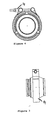
- an example coupling has a first member 1 which includes a first flange 2 and a second member 3 which includes a second flange 4.
- the second member 3 engages with the first member 1 to define a retaining cavity 5.
- a seal 6 is provided between the first 1 and second 3 members. The seal 6, dependent upon its shape and material, may also provide a load bearing function.
- a third member 7 fits in the retaining cavity 5, with a first load bearing member 8, formed, in this example, from carbon, positioned between the third member 7 and the second member 3.
- This load bearing member 8 in use, provides a load bearing surface in contact with the inner surface of the second member 3 and provides the dual function of sealing and the enabling of relative movement of the second 3 and third 7 members with the application of relatively low force.
- the third member 7 can be rotated within the retaining cavity 5, with uninhibited torsional rotation, improving ease of installation and ensuring that the coupling can move in use to compensate for movement in, for example, the aircraft that it is installed in.
- Figure 2 shows a second example coupling in which components which correspond to those in the first example are numbered identically.
- the seal 6, has a slightly different shape, and the coupling has a second load bearing member 10 in between the third member 7 and the first member 1.
- the second load bearing member 10 in use, provides an additional load bearing surface in contact with the surface of the first member 1 as well as providing additional sealing function.
- Figures 3 and 4 show a coupling of the type shown in figures 1 and 2 held together with a clamp 14 which clamps around the first 2 and second 4 flanges.
- the clamp 14 may be of a known standard type. It will, of course, be appreciated that alternative retaining arrangements, such as screw threads and bayonet fixings may be employed.
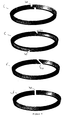
- Figure 5 shows example configurations of the seal 6, from which it can be seen that the seal 6 has a break 20 in it to allow assembly.
- the break 20 is either an angled or stepped cut through the seal 6 to improve the sealing qualities of the seal 6 and to reduce the likelihood of fluid flow through the break 20.
Landscapes
- Engineering & Computer Science (AREA)
- General Engineering & Computer Science (AREA)
- Mechanical Engineering (AREA)
- Joints Allowing Movement (AREA)
Priority Applications (3)
| Application Number | Priority Date | Filing Date | Title |
|---|---|---|---|
| EP20020257209 EP1411289A1 (de) | 2002-10-17 | 2002-10-17 | Flexible Kupplung |
| EP03256224A EP1441166A3 (de) | 2002-10-17 | 2003-10-02 | Flexible Kupplung |
| US10/684,803 US20040130149A1 (en) | 2002-10-17 | 2003-10-15 | Flexible coupling |
Applications Claiming Priority (1)
| Application Number | Priority Date | Filing Date | Title |
|---|---|---|---|
| EP20020257209 EP1411289A1 (de) | 2002-10-17 | 2002-10-17 | Flexible Kupplung |
Publications (1)
| Publication Number | Publication Date |
|---|---|
| EP1411289A1 true EP1411289A1 (de) | 2004-04-21 |
Family
ID=32039215
Family Applications (1)
| Application Number | Title | Priority Date | Filing Date |
|---|---|---|---|
| EP20020257209 Withdrawn EP1411289A1 (de) | 2002-10-17 | 2002-10-17 | Flexible Kupplung |
Country Status (2)
| Country | Link |
|---|---|
| US (1) | US20040130149A1 (de) |
| EP (1) | EP1411289A1 (de) |
Cited By (1)
| Publication number | Priority date | Publication date | Assignee | Title |
|---|---|---|---|---|
| EP1631764A2 (de) * | 2003-06-06 | 2006-03-08 | Delaware Capital Formation, Inc. | Flexible gasleitungskupplung |
Families Citing this family (3)
| Publication number | Priority date | Publication date | Assignee | Title |
|---|---|---|---|---|
| US7600791B2 (en) * | 2004-09-10 | 2009-10-13 | Emcon Technologies Llc | Exhaust system |
| DE102006029705B4 (de) * | 2006-06-28 | 2009-08-20 | Airbus Deutschland Gmbh | Rohrverbindung und Rohrverbindungssystem mit derartigen Rohrverbindungen |
| FR3087868B1 (fr) * | 2018-10-25 | 2021-05-07 | Airbus Operations Sas | Dispositif de raccordement de deux conduits d’une canalisation comportant un jeu de collerettes tronconiques et canalisation comprenant ledit dispositif de raccordement |
Citations (4)
| Publication number | Priority date | Publication date | Assignee | Title |
|---|---|---|---|---|
| US1434631A (en) * | 1921-01-22 | 1922-11-07 | James J Reynolds | Flexible pipe joint |
| GB1321703A (en) * | 1970-09-24 | 1973-06-27 | Aeroquip Ag | Ball joint for fluid lines |
| US4893847A (en) * | 1988-07-05 | 1990-01-16 | Stainless Steel Products, Inc. | Bearing seal for universal ball joint |
| FR2799260A1 (fr) * | 1999-10-04 | 2001-04-06 | Acc La Jonchere | Joint articule destine, notamment, a relier entre elles deux conduites d'ecoulement de fluide liquide ou gazeux |
Family Cites Families (17)
| Publication number | Priority date | Publication date | Assignee | Title |
|---|---|---|---|---|
| US3276795A (en) * | 1966-10-04 | Pipe couplings | ||
| US937533A (en) * | 1906-10-03 | 1909-10-19 | Kelly Arnold Mfg Company | Pipe-coupling. |
| US1057939A (en) * | 1912-01-31 | 1913-04-01 | Andrew H Cooper | Ball-and-socket pipe-coupling. |
| US1155495A (en) * | 1913-12-29 | 1915-10-05 | John S Leake | Method of making lubricated joints. |
| US1568649A (en) * | 1921-06-08 | 1926-01-05 | Leonidas D Woodruff | Ball joint |
| US1563161A (en) * | 1924-04-26 | 1925-11-24 | Manville Johns Inc | Pressure packing |
| US3178207A (en) * | 1960-06-17 | 1965-04-13 | Thiokol Chemical Corp | Universal tube joint with bearing inserts |
| US3276796A (en) * | 1965-12-13 | 1966-10-04 | American Cast Iron Pipe Co | Boltless flexible pipe joint |
| US3454288A (en) * | 1967-12-22 | 1969-07-08 | Joseph J Mancusi Jr | Pressure-balanced swivel pipe coupling |
| US3544137A (en) * | 1969-01-17 | 1970-12-01 | Aeroquip Corp | Ball joint for fluid lines |
| US3951418A (en) * | 1974-01-21 | 1976-04-20 | W. S. Shamban & Co. | Moving captive seal construction usable under high temperature and cryogenic conditions |
| US3944263A (en) * | 1975-03-14 | 1976-03-16 | Hydrotech International, Inc. | Dynamic pipe coupling |
| US4071269A (en) * | 1976-05-28 | 1978-01-31 | Pressure Science Incorporated | Flexible piping joint |
| US4054306A (en) * | 1976-05-28 | 1977-10-18 | Pressure Science Incorporated | Tube and cylindrical surface sealing apparatus |
| US4457523A (en) * | 1982-10-29 | 1984-07-03 | Pressure Science Incorporated | Torsionally flexible metallic annular seal |
| US4779901A (en) * | 1983-12-29 | 1988-10-25 | Eg&G Pressure Science, Inc. | Sealed rigid pipe joint |
| US6237965B1 (en) * | 1999-07-27 | 2001-05-29 | Hsien-Wen Kuo | Leak-free flexible conduit |
-
2002
- 2002-10-17 EP EP20020257209 patent/EP1411289A1/de not_active Withdrawn
-
2003
- 2003-10-15 US US10/684,803 patent/US20040130149A1/en not_active Abandoned
Patent Citations (4)
| Publication number | Priority date | Publication date | Assignee | Title |
|---|---|---|---|---|
| US1434631A (en) * | 1921-01-22 | 1922-11-07 | James J Reynolds | Flexible pipe joint |
| GB1321703A (en) * | 1970-09-24 | 1973-06-27 | Aeroquip Ag | Ball joint for fluid lines |
| US4893847A (en) * | 1988-07-05 | 1990-01-16 | Stainless Steel Products, Inc. | Bearing seal for universal ball joint |
| FR2799260A1 (fr) * | 1999-10-04 | 2001-04-06 | Acc La Jonchere | Joint articule destine, notamment, a relier entre elles deux conduites d'ecoulement de fluide liquide ou gazeux |
Cited By (2)
| Publication number | Priority date | Publication date | Assignee | Title |
|---|---|---|---|---|
| EP1631764A2 (de) * | 2003-06-06 | 2006-03-08 | Delaware Capital Formation, Inc. | Flexible gasleitungskupplung |
| EP1631764A4 (de) * | 2003-06-06 | 2010-12-01 | Capital Formation Inc | Flexible gasleitungskupplung |
Also Published As
| Publication number | Publication date |
|---|---|
| US20040130149A1 (en) | 2004-07-08 |
Similar Documents
| Publication | Publication Date | Title |
|---|---|---|
| US4054306A (en) | Tube and cylindrical surface sealing apparatus | |
| EP1883764B1 (de) | Gelenkverbindungsstück für rohre | |
| JP5128490B2 (ja) | プロセス制御バルブに使用するフレキシブルシール | |
| US6709023B2 (en) | Flexible slide joint | |
| US4893847A (en) | Bearing seal for universal ball joint | |
| US3734546A (en) | Flexible pipe connection | |
| US5505498A (en) | Flexible pressure-energized joint | |
| US4448449A (en) | Flexible piping joint and method of forming same | |
| US4068864A (en) | Single element flexible connection | |
| US5702132A (en) | Pivotal link | |
| US8720899B2 (en) | Dynamic sealing | |
| GB2292981A (en) | Pressure-energized sealing rings | |
| EP1411289A1 (de) | Flexible Kupplung | |
| CN104412021A (zh) | 球面排气管接头 | |
| KR20090112047A (ko) | 로터리 액추에이터 및 로터리 액추에이터형 관절구조 | |
| EP3722634B1 (de) | Dämpfer | |
| US10054338B2 (en) | Flexible coupling with rotational capability | |
| EP1441166A2 (de) | Flexible Kupplung | |
| CN220749279U (zh) | 一种不锈钢法兰 | |
| US8424922B2 (en) | Angled flexible coupling with integral outer shield and/or inner liner | |
| CN220891428U (zh) | 一种易于安装的膨胀节 | |
| JPS6098286A (ja) | 配管用継手 | |
| WO1982002581A1 (en) | Fluid flow ductwork |
Legal Events
| Date | Code | Title | Description |
|---|---|---|---|
| PUAI | Public reference made under article 153(3) epc to a published international application that has entered the european phase |
Free format text: ORIGINAL CODE: 0009012 |
|
| AK | Designated contracting states |
Kind code of ref document: A1 Designated state(s): AT BE BG CH CY CZ DE DK EE ES FI FR GB GR IE IT LI LU MC NL PT SE SK TR |
|
| AX | Request for extension of the european patent |
Extension state: AL LT LV MK RO SI |
|
| AKX | Designation fees paid | ||
| REG | Reference to a national code |
Ref country code: DE Ref legal event code: 8566 |
|
| STAA | Information on the status of an ep patent application or granted ep patent |
Free format text: STATUS: THE APPLICATION IS DEEMED TO BE WITHDRAWN |
|
| 18D | Application deemed to be withdrawn |
Effective date: 20041022 |