EP4077995B1 - Fluidkomponentenkörper mit lecktestkanälen - Google Patents
Fluidkomponentenkörper mit lecktestkanälen Download PDFInfo
- Publication number
- EP4077995B1 EP4077995B1 EP20842376.4A EP20842376A EP4077995B1 EP 4077995 B1 EP4077995 B1 EP 4077995B1 EP 20842376 A EP20842376 A EP 20842376A EP 4077995 B1 EP4077995 B1 EP 4077995B1
- Authority
- EP
- European Patent Office
- Prior art keywords
- valve
- manifold
- leak test
- leak
- test
- Prior art date
- Legal status (The legal status is an assumption and is not a legal conclusion. Google has not performed a legal analysis and makes no representation as to the accuracy of the status listed.)
- Active
Links
Images


Classifications
-
- F—MECHANICAL ENGINEERING; LIGHTING; HEATING; WEAPONS; BLASTING
- F16—ENGINEERING ELEMENTS AND UNITS; GENERAL MEASURES FOR PRODUCING AND MAINTAINING EFFECTIVE FUNCTIONING OF MACHINES OR INSTALLATIONS; THERMAL INSULATION IN GENERAL
- F16K—VALVES; TAPS; COCKS; ACTUATING-FLOATS; DEVICES FOR VENTING OR AERATING
- F16K27/00—Construction of housing; Use of materials therefor
- F16K27/003—Housing formed from a plurality of the same valve elements
-
- F—MECHANICAL ENGINEERING; LIGHTING; HEATING; WEAPONS; BLASTING
- F16—ENGINEERING ELEMENTS AND UNITS; GENERAL MEASURES FOR PRODUCING AND MAINTAINING EFFECTIVE FUNCTIONING OF MACHINES OR INSTALLATIONS; THERMAL INSULATION IN GENERAL
- F16K—VALVES; TAPS; COCKS; ACTUATING-FLOATS; DEVICES FOR VENTING OR AERATING
- F16K31/00—Actuating devices; Operating means; Releasing devices
- F16K31/12—Actuating devices; Operating means; Releasing devices actuated by fluid
- F16K31/122—Actuating devices; Operating means; Releasing devices actuated by fluid the fluid acting on a piston
- F16K31/1221—Actuating devices; Operating means; Releasing devices actuated by fluid the fluid acting on a piston one side of the piston being spring-loaded
-
- F—MECHANICAL ENGINEERING; LIGHTING; HEATING; WEAPONS; BLASTING
- F16—ENGINEERING ELEMENTS AND UNITS; GENERAL MEASURES FOR PRODUCING AND MAINTAINING EFFECTIVE FUNCTIONING OF MACHINES OR INSTALLATIONS; THERMAL INSULATION IN GENERAL
- F16K—VALVES; TAPS; COCKS; ACTUATING-FLOATS; DEVICES FOR VENTING OR AERATING
- F16K31/00—Actuating devices; Operating means; Releasing devices
- F16K31/12—Actuating devices; Operating means; Releasing devices actuated by fluid
- F16K31/122—Actuating devices; Operating means; Releasing devices actuated by fluid the fluid acting on a piston
- F16K31/1225—Actuating devices; Operating means; Releasing devices actuated by fluid the fluid acting on a piston with a plurality of pistons
-
- F—MECHANICAL ENGINEERING; LIGHTING; HEATING; WEAPONS; BLASTING
- F16—ENGINEERING ELEMENTS AND UNITS; GENERAL MEASURES FOR PRODUCING AND MAINTAINING EFFECTIVE FUNCTIONING OF MACHINES OR INSTALLATIONS; THERMAL INSULATION IN GENERAL
- F16K—VALVES; TAPS; COCKS; ACTUATING-FLOATS; DEVICES FOR VENTING OR AERATING
- F16K31/00—Actuating devices; Operating means; Releasing devices
- F16K31/12—Actuating devices; Operating means; Releasing devices actuated by fluid
- F16K31/122—Actuating devices; Operating means; Releasing devices actuated by fluid the fluid acting on a piston
- F16K31/1226—Actuating devices; Operating means; Releasing devices actuated by fluid the fluid acting on a piston the fluid circulating through the piston
-
- F—MECHANICAL ENGINEERING; LIGHTING; HEATING; WEAPONS; BLASTING
- F16—ENGINEERING ELEMENTS AND UNITS; GENERAL MEASURES FOR PRODUCING AND MAINTAINING EFFECTIVE FUNCTIONING OF MACHINES OR INSTALLATIONS; THERMAL INSULATION IN GENERAL
- F16K—VALVES; TAPS; COCKS; ACTUATING-FLOATS; DEVICES FOR VENTING OR AERATING
- F16K37/00—Special means in or on valves or other cut-off apparatus for indicating or recording operation thereof, or for enabling an alarm to be given
- F16K37/0066—Hydraulic or pneumatic means
-
- F—MECHANICAL ENGINEERING; LIGHTING; HEATING; WEAPONS; BLASTING
- F16—ENGINEERING ELEMENTS AND UNITS; GENERAL MEASURES FOR PRODUCING AND MAINTAINING EFFECTIVE FUNCTIONING OF MACHINES OR INSTALLATIONS; THERMAL INSULATION IN GENERAL
- F16K—VALVES; TAPS; COCKS; ACTUATING-FLOATS; DEVICES FOR VENTING OR AERATING
- F16K37/00—Special means in or on valves or other cut-off apparatus for indicating or recording operation thereof, or for enabling an alarm to be given
- F16K37/0075—For recording or indicating the functioning of a valve in combination with test equipment
- F16K37/0091—For recording or indicating the functioning of a valve in combination with test equipment by measuring fluid parameters
-
- F—MECHANICAL ENGINEERING; LIGHTING; HEATING; WEAPONS; BLASTING
- F16—ENGINEERING ELEMENTS AND UNITS; GENERAL MEASURES FOR PRODUCING AND MAINTAINING EFFECTIVE FUNCTIONING OF MACHINES OR INSTALLATIONS; THERMAL INSULATION IN GENERAL
- F16K—VALVES; TAPS; COCKS; ACTUATING-FLOATS; DEVICES FOR VENTING OR AERATING
- F16K7/00—Diaphragm valves or cut-off apparatus, e.g. with a member deformed, but not moved bodily, to close the passage ; Pinch valves
- F16K7/12—Diaphragm valves or cut-off apparatus, e.g. with a member deformed, but not moved bodily, to close the passage ; Pinch valves with flat, dished, or bowl-shaped diaphragm
- F16K7/14—Diaphragm valves or cut-off apparatus, e.g. with a member deformed, but not moved bodily, to close the passage ; Pinch valves with flat, dished, or bowl-shaped diaphragm arranged to be deformed against a flat seat
- F16K7/17—Diaphragm valves or cut-off apparatus, e.g. with a member deformed, but not moved bodily, to close the passage ; Pinch valves with flat, dished, or bowl-shaped diaphragm arranged to be deformed against a flat seat the diaphragm being actuated by fluid pressure
-
- G—PHYSICS
- G01—MEASURING; TESTING
- G01M—TESTING STATIC OR DYNAMIC BALANCE OF MACHINES OR STRUCTURES; TESTING OF STRUCTURES OR APPARATUS, NOT OTHERWISE PROVIDED FOR
- G01M3/00—Investigating fluid-tightness of structures
- G01M3/02—Investigating fluid-tightness of structures by using fluid or vacuum
- G01M3/04—Investigating fluid-tightness of structures by using fluid or vacuum by detecting the presence of fluid at the leakage point
- G01M3/20—Investigating fluid-tightness of structures by using fluid or vacuum by detecting the presence of fluid at the leakage point using special tracer materials, e.g. dye, fluorescent material, radioactive material
- G01M3/22—Investigating fluid-tightness of structures by using fluid or vacuum by detecting the presence of fluid at the leakage point using special tracer materials, e.g. dye, fluorescent material, radioactive material for pipes, cables or tubes; for pipe joints or seals; for valves; for welds; for containers, e.g. radiators
- G01M3/224—Investigating fluid-tightness of structures by using fluid or vacuum by detecting the presence of fluid at the leakage point using special tracer materials, e.g. dye, fluorescent material, radioactive material for pipes, cables or tubes; for pipe joints or seals; for valves; for welds; for containers, e.g. radiators for valves
Definitions
- Fluid systems often include multiple valves arranged for mixing, switching, purging, and other such controls of one or more types of fluid, for example, for gas distribution employed in the manufacture of semiconductor wafers. While such fluid control systems may be constructed by welding or otherwise connecting individual valves in a desired configuration, such arrangements may be undesirable due to the time and cost of construction, potential leak points at the many connections, overall size of the assembly, and other such factors.
- valve manifolds have often been used to address one or more of these issues by providing a single body block, machined for desired flow path arrangements, in which multiple valve assemblies are installed to control flow at multiple points within the multi-ported manifold body block.
- the manifold body block itself may be expensive and difficult to machine, and may be limited in the shapes and orientations of internal ports that may be provided. Additionally, polished surface finish requirements for the manifold body flow paths may be difficult to maintain where the flow paths are extended and/or complex (non-straight).
- a manifold body includes at least first and second valve body segments each comprising an upper perimeter wall portion defining a valve cavity and a lower base portion defining one or more flow ports, a unified leak test port, a first branch leak test passage extending from the unified leak test port to an outer peripheral portion of the valve cavity of the first valve body segment, radially outward of an outer seal surface in the valve cavity, and a second branch leak test passage extending from the unified leak test port to an outer peripheral portion of the valve cavity of the second valve body segment, radially outward of an outer seal surface in the valve cavity.
- a valve body in another exemplary embodiment of the present disclosure, includes an upper perimeter wall portion defining a valve cavity and a lower base portion defining one or more flow ports, and a leak test passage formed in the upper perimeter wall portion of the valve body, with a first portion of the leak test passage extending axially through the upper perimeter wall portion to a leak test port exposed on an end surface of the upper perimeter wall portion, and a second portion of the leak test passage extending laterally or radially through a lower end of the upper perimeter wall portion to the valve cavity to intersect with an outer peripheral portion of the valve cavity, radially outward of an outer seal surface in the valve cavity.
- a manifold assembly in another exemplary embodiment of the present disclosure, includes a manifold body having at least first and second valve body segments, a first valve subassembly assembled with the first valve body segment and a second valve subassembly assembled with the second valve body segment.
- Each of the first and second valve body segments includes an upper perimeter wall portion defining a valve cavity and a lower base portion defining a central flow port and an offset flow port; a unified leak test port; a first branch leak test passage extending from the unified leak test port to an outer peripheral portion of the valve cavity of the first valve body segment, radially outward of an outer seal surface in the valve cavity; and a second branch leak test passage extending from the unified leak test port to an outer peripheral portion of the valve cavity of the second valve body segment, radially outward of an outer seal surface in the valve cavity.
- Each of the first and second valve subassemblies includes a flexible diaphragm, an annular seat carrier received in the valve cavity and including a lower seal portion that seals against a recessed surface around the central flow port and an upper seal portion that seals against the diaphragm when the diaphragm is moved to the closed position, and a threaded bonnet nut installed in the valve cavity to clamp the seat carrier against the outer seal surface in the valve cavity to form a body seal.
- a valve assembly in another exemplary embodiment of the present disclosure, includes a valve body and a valve subassembly.
- the valve body includes an upper perimeter wall portion defining a valve cavity and a lower base portion defining one or more flow ports, and a leak test passage formed in the upper perimeter wall portion of the valve body, with a first portion of the leak test passage extending axially through the upper perimeter wall portion to a leak test port exposed on an end surface of the upper perimeter wall portion, and a second portion of the leak test passage extending laterally or radially through a lower end of the upper perimeter wall portion to the valve cavity to intersect with an outer peripheral portion of the valve cavity, radially outward of an outer seal surface in the valve cavity.
- the valve subassembly includes a flexible diaphragm, an annular seat carrier received in the valve cavity and including a lower seal portion that seals against a recessed surface around the central flow port and an upper seal portion that seals against the diaphragm when the diaphragm is moved to the closed position, and a threaded bonnet nut installed in the valve cavity to clamp the seat carrier against the outer seal surface in the valve cavity to form a body seal.
- a method for leak testing first and second valves installed in first and second valve cavities in a multi-valve manifold body.
- the manifold assembly is provided in a fluid system under a vacuum, and the manifold assembly is connected with a leak detection device.
- a test fluid is supplied to a unified leak test port in the manifold body, such that the test fluid is transmitted through first and second branching leak test passages to outer peripheral portions of the first and second valve cavities.
- the leak detection device is used to measure ingress of the test fluid past first and second body seals between the first and second valves and the first and second valve cavities.
- the test fluid is sequentially supplied to first and second valve leak test ports, such that the test fluid is sequentially transmitted through first and second valve leak test passages to the outer peripheral portions of the first and second valve cavities.
- the leak detection device is used to measure ingress of the test fluid past the first body seal, and to measure ingress of the test fluid past the second body seal.
- the term “vertical” is used to describe a direction substantially perpendicular to a base (or bottom) surface of the fluid component body
- the term “horizontal” is used to describe a direction substantially parallel to the base surface of the fluid component body. It is to be understood that the fluid component body may be mounted or arranged in any suitable orientation (e.g., with the base surface of the fluid component body extending substantially vertically, or at some other angle).
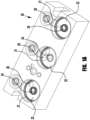
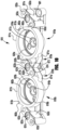
- FIG. 1 illustrates an exemplary conventional three-valve manifold 10 having a manifold body block 20 and diaphragm valves 30 installed in corresponding valve cavities 21 machined in the body block 20.
- Each valve cavity 21 includes a recessed surface or trepan 22 and a bore wall 23 ( FIG. 1A ), with at least first and second ports 24, 26 provided in the recessed surface 22.
- each valve 30 includes a valve subassembly 40 and an actuator 50.
- the exemplary valve subassemblies 40 each include a flexible diaphragm 41 and an annular seat carrier 42 received in the valve cavity 21 and including a lower seal portion 44 that seals against the recessed surface 22 around the first port 24 and an upper seal portion 45 that seals against the diaphragm 41 when the diaphragm is moved to the closed position.
- a threaded retainer or bonnet nut 46 is installed in the valve cavity 21 to clamp the seat carrier 42 and diaphragm 41 against the recessed surface 22, with an outer male threaded portion of the retainer 46 mating with an inner female threaded portion of the bore wall 23.
- a male threaded bonnet portion 51 of the actuator 50 is threaded into a female threaded portion of the retainer 46 to connect the actuator 50 with the valve subassembly 40 and to position the actuator stem 52 for operative engagement (e.g., using intermediary button 54) with the diaphragm 41.
- a similar actuated valve assembly is shown and described in co-owned US Patent No. 9,863,542 (the "'542 Patent").
- a multi-valve manifold body may be formed as a plurality of discrete valve body segments and conduit segments integrated into a single-piece, monolithic construction having a reduced size, weight, and raw material usage as compared to a corresponding manifold body block.
- Exemplary multi-valve manifold bodies including integrated valve body and conduit segments are shown and described in co-pending US Patent Application Pub. No. 2020/0003318 (the "'318 Application").
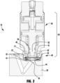
- valves such as, for example, the valve arrangements of the above incorporated '542 Patent and '318 Application, and as shown in FIG. 2 herein, include a body seal 43 (e.g., gasket, packing, annular sealing bead) providing a leak-tight seal between an internal valve cavity and the external atmosphere surrounding the valve.
- a body seal 43 e.g., gasket, packing, annular sealing bead
- the seat carrier 42 is provided with a lower circumferential bead 43 that seals against an outer periphery of the valve cavity 21 when the threaded retainer 46 is tightened against the seat carrier 42.
- a leak test passage may be provided with the valve, extending from an exterior opening or leak test port to the valve cavity, at a location radially outward of the body seal.
- a test fluid e.g., a tracer gas, such as helium or hydrogen
- the valve may be installed in a fluid system under a vacuum and connected with a leak detection device (e.g., mass spectrometer) configured to detect the ingress of the test fluid past the body seal and into the valve cavity.
- the valve may be installed in a fluid system under positive pressure, with leak testing being implemented (e.g., using a sensor or bubbling leak detection fluid) at the leak detecting port to detect leakage of the positive pressure system fluid past the body seal.
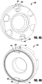
- a valve 400 (e.g., similar to the valve 10 of FIG. 2 ) having a bonnet nut 446 that is threadably installed in the valve cavity 412 to clamp an outer peripheral bead portion or body seal 443 of a seat carrier 442 against an outer seal surface 425 of the valve cavity 412, is provided with an axially extending outer peripheral groove 447 in the bonnet nut 446 (see FIG. 4 ) that defines a leak test passage extending to an outer peripheral portion of the valve cavity 412, radially outward of the outer seal surface 425.
- An upper or outer end of the groove 447 defines a leak test port 448, such that a test fluid (e.g., a tracer gas, such as helium or hydrogen) supplied to the leak test port 448 flows to the outer peripheral portion of the valve cavity 412.
- a test fluid e.g., a tracer gas, such as helium or hydrogen
- a leak detection device e.g., mass spectrometer
- ingress of the test fluid past the body seal 443 e.g., due to a discontinuity or contaminant on the bead portion 443 or outer seal surface 425
- into the valve cavity may be detected to identify a body seal leak.
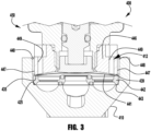
- the bonnet nut 446 may be provided with multiple outer peripheral grooves 447, for example, to facilitate convenient positioning of a leak test port regardless of rotational orientation of the bonnet nut 446 with respect to the valve body 410. Additionally, the bonnet nut 446 may include one or more test holes or axially extending inner test passages 449 that extend through the bonnet nut 446 to intersect with the valve cavity radially inward of the body seal and above the diaphragm 441, for example, to test for leakage through the diaphragm 441 (e.g., due to a crack in the diaphragm), for example, during the same vacuum leak test procedure described above.
- the bonnet nut 446 may instead be provided with one or more radially extending test passages to permit test fluid flow between the outer peripheral portion of the valve cavity 412 and a portion of the valve cavity radially inward of the body seal and above the diaphragm 441. While many different types of radial test passages may be utilized, in an exemplary embodiment, as shown in phantom in FIG. 3 , the lower, diaphragm engaging bead 435 of the bonnet nut 446 may be provided with one or more notches 439 defining radial test passages (see FIG. 4B ).
- a valve in another exemplary embodiment, may be provided with a valve body having an integrated leak test passage extending from an external surface of the valve body to an outer peripheral portion of a valve cavity radially outward of a body seal surface.
- Such an arrangement may provide for consistent placement of the leak test port on the valve (e.g., as compared to a leak test port defined by a bonnet nut).
- a leak test passage may be disposed in an upper perimeter wall portion of the valve body that defines the valve cavity.
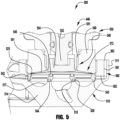
- a valve 500 includes a valve body 510 having an upper perimeter wall portion 511 defining a valve cavity 512, and a lower base portion 514 defining a central flow port 516 and an offset flow port 517 (see FIG. 6 ).
- a leak test passage 560 is formed in the upper perimeter wall portion 511 of the valve body 510, with a first portion 561 of the leak test passage extending vertically or axially through the upper perimeter wall portion 511 to a leak test port 563 exposed on an end surface 513 of the upper perimeter wall portion, and a second portion 562 of the leak test passage 560 extending laterally or radially through a base or lower end of the upper perimeter wall portion to the valve cavity to intersect with an outer peripheral portion of the valve cavity 512, radially outward of an outer seal surface 525 in the valve cavity 512.
- valve 500 of FIG. 5 incudes a valve subassembly 540 and an actuator 550.
- the exemplary valve subassembly 540 includes a flexible diaphragm 541 and an annular seat carrier 542 received in the valve cavity 512 and including a lower seal portion 544 that seals against the recessed surface 528 around the central flow port 516 and an upper seal portion 545 that seals against the diaphragm 541 when the diaphragm is moved to the closed position.
- a threaded retainer or bonnet nut 546 is installed in the valve cavity 512 to clamp an outer peripheral bead portion or body seal 543 of the seat carrier 542 against the outer seal surface 525 of the valve cavity 512, with an outer male threaded portion of the retainer 546 mating with an inner female threaded portion of the upper perimeter wall portion 511.
- a male threaded bonnet portion 551 of the actuator 550 is threaded into a female threaded portion of the bonnet nut 546 to connect the actuator 550 with the valve subassembly 540 and to position the actuator stem 552 for operative engagement (e.g., using intermediary button 554) with the diaphragm 541.
- valve 500 When the valve 500 is installed in a fluid system under a vacuum and connected with a leak detection device (e.g., mass spectrometer) and a test fluid (e.g., a tracer gas, such as helium or hydrogen) is supplied to the leak test port 563, ingress of the test fluid past the body seal 543 (e.g., due to a discontinuity or contaminant on the bead portion 543 or outer seal surface 525) and into the valve cavity may be detected to identify a body seal leak.
- the bonnet nut may be provided with one or more inner test passages or radial test passages (as shown in the embodiment of FIG. 3 ) to simultaneously test for leakage through the diaphragm (e.g., due to a crack in the diaphragm).
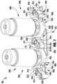
- FIGS. 7-9 illustrate an exemplary two-valve manifold assembly 600 having a manifold body 610 (see FIGS. 10-11 ) including first and second valve body segments 610a, 610b assembled with corresponding first and second valves 630a, 630b, each including a valve subassembly 640a, 640b and an actuator 650a, 650b.
- the valve subassemblies 640a, 640b may be similar to the valve subassembly 540 of FIG. 5 , as described in greater detail above, the components for which are numbered accordingly.
- Each of the first and second valve body segments 610a, 610b has an upper perimeter wall portion 611a, 611b defining a valve cavity 612a, 612b, and a lower base portion 614a, 614b defining a central flow port 616a, 616b and offset flow ports 617a, 617b, 618b.
- Adjacent perimeter wall portions 611a, 611b of adjacent valve body segments 610a, 610b may be joined or fused together, for example, to facilitate manufacturing, to reduce overall size of the manifold body 610 and/or to strengthen or reinforce these wall portions.
- Apertured mounting bosses 601 may be provided, for example, fused with an adjacent portion of the upper perimeter wall of one of the first and second valve segments, to facilitate mounting of the manifold within a system (e.g., to a plate or other such base component of a fluid system).
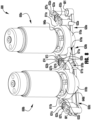
- first and second valve body segments 610a, 610b are connected with first, second, third, and fourth flow conduit segments 620a, 620b, 620c, 620d, as shown in FIG. 11 .
- the first flow conduit segment 620a includes a first flow passage 621a extending between a first end port 623a and the central flow port 616a of the first valve body segment 610a.
- the second flow conduit segment 620b includes a second flow passage 621b extending between a second end port 623b and the central flow port 616b of the second valve body segment 610b.
- the third flow conduit segment 620c includes a third flow passage 621c extending between a third end port 623c and the second offset port 618b of the second valve body segment 610b.
- the fourth flow conduit segment 620d includes a fourth flow passage 621d extending between the offset port 617a of the first valve body segment 610a and the first offset port 617b of the second valve body segment 610b.
- the end ports 623a, 623b, 623c include tubular portions 622a, 622b, 622c extending upward or vertically, spaced apart from the valve body segment perimeter wall portions 611a, 611b, to modular mount surfaces 627a, 627b, 627c including seal counterbores 631a, 631b, 631c and fastener bores 632a, 632b, 632c for accommodating modular C-seal connections.
- the base portions 614a, 614b of the valve body segments 610a, 610b may be tapered (e.g., to have an outer diameter smaller than an outer diameter of the perimeter wall 611a, 611b), for example, to reduce material usage and/or to provide clearance for one or more of the flow conduit segments 620a, 620b, 620c, 620d, such that a horizontal flow path portion 624a, 624b, 624c of the flow conduit segment is at least partially laterally aligned with the valve cavity of at least one of the valve body segments.
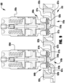
- a leak test passage 660a, 660b is formed in the upper perimeter wall portion 611a, 611b of each valve body segment 610a, 610b, with a first portion 661a, 661b of the leak test passage extending vertically or axially through the upper perimeter wall portion 611a, 611b to a leak test port 663a, 663b exposed on an end surface 613a, 613b of the upper perimeter wall portion, and a second portion 662a, 662b of the leak test passage 660a, 660b extending laterally or radially through a base or lower end of the upper perimeter wall portion to the valve cavity 612a, 612b to intersect with an outer peripheral portion of the valve cavity, radially outward of the outer seal surface 625a, 625b.
- the manifold assembly 600 is installed in a fluid system under a vacuum and connected with a leak detection device (e.g., mass spectrometer) and a test fluid (e.g., a tracer gas, such as helium or hydrogen) is sequentially supplied to each of the leak test ports 663a, 663b, and the leak detection device is used to measure ingress of the test fluid past the body seal 643a, 643b (e.g., due to a discontinuity or contaminant on the bead portion 643a, 643b or outer seal surface 625a, 625b) and into the valve cavity to identify a body seal leak.
- a leak detection device e.g., mass spectrometer
- a test fluid e.g., a tracer gas, such as helium or hydrogen
- bonnet nuts 646a, 646b may be provided with one or more inner test passages or radial test passages (as shown in the embodiment of FIG. 3 ) to simultaneously test for leakage through the diaphragm (e.g., due to a crack in the diaphragm).
- a multi-valve manifold body may be provided with an integrated, unified leak test port with branching leak test passages intersecting with a plurality of valve cavities of the manifold body, for simultaneously testing of the valve body seals of two or more of the manifold valves.
- application of a test fluid to the unified leak test port may provide for confirmation of leakage past at least one of the body seals of the plurality of valve body segments.
- individual leak test ports and passages may be utilized to identify which of the valve body segments is exhibiting body seal leakage.
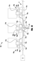
- FIG. 12 schematically illustrates a multi-valve manifold assembly 700 including a unified leak test port 773 connected by branching leak test passages 770a, 770b, 770c to the valve cavities 712a, 712b, 712c of multiple valve body segments 710a, 710b, 710c for collectively testing for leakage past the body seals 743a, 743b, 743c of the multiple valves 730a, 730b, 730c of the manifold assembly, and individual leak test ports 763a, 763b, 763c connected by leak test passages 760a, 760b, 760c to the valve cavities for independently testing for leakage past the body seals of each valve of the manifold assembly. While the manifold assembly 700 of FIG.
- unified and individual leak test ports may be provided for manifold assemblies having a different number of valves (e.g., two, or four or more). Additionally, a unified leak test port may be connected with fewer than all of the valves of a multi-valve manifold assembly.
- a manifold assembly may include a first unified leak test port for testing leakage past the body seals of a first plurality of valves of the manifold assembly, and a second unified leak test port for testing leakage past the body seals of a second plurality of valves of the manifold assembly.
- the manifold assembly 700 is installed in a fluid system S under a vacuum and connected with a leak detection device D (e.g., mass spectrometer) and a test fluid (e.g., a tracer gas, such as helium or hydrogen) is supplied to the unified leak test port 773 and transmitted through the branching leak test passages 770a, 770b, 770c to outer peripheral portions of the valve cavities 712a, 712b, 712c, and the leak detection device D is used to measure ingress of the test fluid past the body seals 743a, 743b, 743c and into the valve cavities to identify a body seal leak.
- a leak detection device D e.g., mass spectrometer
- a test fluid e.g., a tracer gas, such as helium or hydrogen
- the leak detection device D If no leakage is detected by the leak detection device D (e.g., detected helium sufficient to indicate leakage), no further leak testing is needed. If leakage is detected by the leak detection device, the test fluid is sequentially supplied to each of the individual leak test ports 763a, 763b, 763c and the leak detection device D is used to measure ingress of the test fluid past each body seal 743a, 743b, 743c to determine which valve body seals are exhibiting leakage.
- the leak detection device D is used to measure ingress of the test fluid past each body seal 743a, 743b, 743c to determine which valve body seals are exhibiting leakage.
- the manifold body 610 includes an integrated unified leak test port 673 connected with the valve cavities 612a, 612b of the valve body segments 610a, 610b by leak test passages 670a, 670b branching from the leak test port, such that a first end of each leak test passage intersects with the leak test port, and a second end of each leak test passage intersects with an outer peripheral portion of the valve cavity 612a, 612b, radially outward of the outer seal surface 625a, 625b.
- the leak test port 673 and leak test passages 670a, 660b are defined by vent conduit segments 674, 671a, 671b integrally formed with the manifold body 610.
- the leak test port and leak test passages may be defined by conduits attached to or assembled with the manifold body (e.g., by welding, brazing, fitting connections), or by passages formed in a manifold block body (e.g., by drilling, machining, etc.).
- the leak test port 673 is centrally disposed between the two valve body segments 610a, 610b, for example, to facilitate uniform flow of a supplied test fluid (e.g., helium) to the two leak test passages 670a, 670b.
- the interior bore of the leak test port 673 may be contoured (e.g., conical) to closely receive a test fluid supply tube, for example, to more efficiently deliver test fluid to the leak test passages.
- the manifold assembly is installed in a fluid system under a vacuum and connected with a leak detection device (e.g., mass spectrometer) and a test fluid (e.g., a tracer gas, such as helium or hydrogen) is supplied to a unified leak test port 673 and transmitted through branching leak test passages 670a, 670b to outer peripheral portions of the valve cavities 612a, 612b, and the leak detection device is used to measure ingress of the test fluid past the body seal (e.g., due to a discontinuity or contaminant on the bead portion 643a, 643b or outer seal surface 625a, 625b) and into the valve cavity to identify a body seal leak.
- a leak detection device e.g., mass spectrometer
- a test fluid e.g., a tracer gas, such as helium or hydrogen
- bonnet nuts 646a, 646b may be provided with one or more inner test passages or radial test passages (as shown in the embodiment of FIG. 3 ) to simultaneously test for leakage through the diaphragm (e.g., due to a crack in the diaphragm).
- the leak detection device If no leakage is detected by the leak detection device (e.g., detected helium sufficient to indicate leakage), no further leak testing is needed. If leakage is detected by the leak detection device, the test fluid is sequentially supplied to each of the individual leak test ports 663a, 663b, and the leak detection device is used to measure ingress of the test fluid past each body seal (and optionally, through each diaphragm) to determine which valve body seals (and/or diaphragms) are exhibiting leakage.
- the leak detection device is used to measure ingress of the test fluid past each body seal (and optionally, through each diaphragm) to determine which valve body seals (and/or diaphragms) are exhibiting leakage.
- a fluid component body e.g., a manifold body
- a fluid component body may make the body difficult to manufacture using conventional machining, molding, or casting techniques.
- a fluid component body for example, the manifold bodies of the above incorporated '542 Patent and '318 Application, and the manifold bodies explicitly described and shown herein, may be fabricated using additive manufacturing to produce a monolithic body having discrete, but partially joined or fused, valve body segments and conduit segments.
- additive manufacturing techniques include, for example: laser powder bed fusion (direct metal laser sintering or "DMLS,” selective laser sintering/melting or “SLS/SLM,” or layered additive manufacturing or “LAM”), electron beam powder bed fusion (electron beam melting or “EBM”), ultrasonic additive manufacturing ("UAM”), or direct energy deposition (laser powder deposition or “LPD,” laser wire deposition or “LWD,” laser engineered net-shaping or “LENS,” electron beam wire deposition).
- DMLS direct metal laser sintering or "DMLS,” selective laser sintering/melting or “SLS/SLM,” or layered additive manufacturing or “LAM”
- EBM electron beam powder bed fusion
- UAM ultrasonic additive manufacturing
- LPD laser powder deposition
- LWD laser wire deposition
- LENS laser engineered net-shaping
Landscapes
- Engineering & Computer Science (AREA)
- General Engineering & Computer Science (AREA)
- Mechanical Engineering (AREA)
- Physics & Mathematics (AREA)
- Fluid Mechanics (AREA)
- General Physics & Mathematics (AREA)
- Valve Housings (AREA)
- Examining Or Testing Airtightness (AREA)
- Details Of Valves (AREA)
Claims (15)
- Verteilerkörper (610), umfassend:
wenigstens ein erstes und zweites Ventilkörpersegment (610a, 610b), die jeweils einen oberen Umfangswandabschnitt (611a, 611b), der einen Ventilhohlraum (612a, 612b) definiert, und einen unteren Basisabschnitt (614a, 614b) umfassen, der einen oder mehrere Strömungsanschlüsse (616a, 616b, 617a, 617b) definiert, dadurch gekennzeichnet, dass der Verteilerkörper ferner umfasst:einen einheitlichen Lecktestanschluss (673);einen ersten Zweig-Lecktestkanal (671a), der sich vom einheitlichen Lecktestanschluss zu einem äußeren Peripherieabschnitt des Ventilhohlraums (612a) des ersten Ventilkörpersegments (610a) radial außerhalb einer äußeren Dichtfläche (625a) im Ventilhohlraum erstreckt; undeinen zweiten Zweig-Lecktestkanal (671b), der sich vom einheitlichen Lecktestanschluss zu einem äußeren Peripherieabschnitt des Ventilhohlraums (612b) des zweiten Ventilkörpersegments (610b) radial außerhalb einer äußeren Dichtfläche (625b) im Ventilhohlraum erstreckt. - Verteilerkörper nach Anspruch 1, wobei jedes des ersten und zweiten Ventilkörpersegments einen Ventil-Lecktestkanal umfasst, der im oberen Umfangswandabschnitt gebildet ist und sich von einem Ventil-Lecktestanschluss, der an einer Endfläche des oberen Umfangswandabschnitts freiliegt, zum Ventilhohlraum erstreckt, um den äußeren Peripherieabschnitt des Ventilhohlraums radial außerhalb der äußeren Dichtfläche zu schneiden.
- Verteilerkörper nach einem der Ansprüche 1 und 2, wobei der obere Umfangswandabschnitt des ersten Ventilkörpersegments einen Abschnitt beinhaltet, der mit einem benachbarten Abschnitt der oberen Umfangswand des zweiten Ventilkörpersegments verschmolzen ist.
- Verteilerkörper nach einem der Ansprüche 1-3, ferner umfassend wenigstens ein Fluidleitungssegment, das sich von einem des einen oder der mehreren Strömungsanschlüsse zu einem Endanschluss erstreckt.
- Verteilerkörper nach Anspruch 4, wobei das wenigstens eine Fluidleitungssegment einen vertikal verlaufenden Abschnitt beinhaltet, der sich zum Endanschluss erstreckt.
- Verteilerkörper nach einem der Ansprüche 1-5, wobei der Verteilerkörper ein monolithisches Bauteil ist.
- Verteilerkörper nach einem der Ansprüche 1-6, wobei wenigstens ein Abschnitt des Verteilerkörpers unter Verwendung additiver Fertigungstechniken hergestellt ist.
- Verteilerbaugruppe (600), beinhaltend den Verteilerkörper nach einem der Ansprüche 1-7, eine erste Ventilunterbaugruppe (640a), die im Ventilhohlraum des ersten Ventilkörpersegments eingebaut ist, und eine zweite Ventilunterbaugruppe (640b), die im Ventilhohlraum des zweiten Ventilkörpersegments eingebaut ist.
- Verteilerbaugruppe nach Anspruch 8, wobei die erste Ventilunterbaugruppe mit einem Gewindeabschnitt der Umfangswand des ersten Ventilkörpersegments gewindemäßig in Eingriff steht und die zweite Ventilunterbaugruppe mit einem Gewindeabschnitt der Umfangswand des zweiten Ventilkörpersegments gewindemäßig in Eingriff steht.
- Verteilerbaugruppe (600), umfassend:den Verteilerkörper nach einem der Ansprüche 1-7; undeine erste Ventilunterbaugruppe (640a), die mit dem ersten Ventilkörpersegment zusammengebaut ist, und eine zweite Ventilunterbaugruppe (640b), die mit dem zweiten Ventilkörpersegment zusammengebaut ist, wobei jede der ersten und zweiten Ventilunterbaugruppe umfasst:eine flexible Membran;einen ringförmigen Sitzträger, der im Ventilhohlraum aufgenommen ist und einen unteren Dichtungsabschnitt, der gegen eine vertiefte Fläche um den zentralen Strömungsanschluss abdichtet, und einen oberen Dichtungsabschnitt beinhaltet, der gegen die Membran abdichtet, wenn die Membran in die geschlossene Position bewegt wird; undeine Gewinde-Haubenmutter, die im Ventilhohlraum eingebaut ist, um den Sitzträger gegen die äußere Dichtfläche im Ventilhohlraum zu klemmen, um eine Körperdichtung zu formen.
- Verteilerbaugruppe nach Anspruch 10, wobei die Haubenmutter der ersten und zweiten Ventilunterbaugruppe einen oder mehrere axial verlaufende innere Prüfkanäle beinhaltet, die sich durch die Haubenmutter erstrecken, um den Ventilhohlraum radial innerhalb der Körperdichtung und oberhalb der Membran zu schneiden.
- Verteilerbaugruppe nach Anspruch 10, wobei die Haubenmutter der ersten und zweiten Ventilunterbaugruppe einen oder mehrere radial verlaufende Prüfkanäle beinhaltet, um einen Testfluidstrom zwischen dem äußeren Peripherieabschnitt des Ventilhohlraums und einem Abschnitt des Ventilhohlraums radial innerhalb der Körperdichtung und oberhalb der Membran zu ermöglichen.
- Verteilerbaugruppe nach einem der Patentansprüche 10-12, wobei jedes des ersten und zweiten Ventilkörpersegments einen Ventil-Lecktestkanal umfasst, der im oberen Umfangswandabschnitt geformt ist und sich von einem Ventil-Lecktestanschluss, der an einer Endfläche des oberen Umfangswandabschnitts freiliegt, zum Ventilhohlraum erstreckt, um den äußeren Peripherieabschnitt des Ventilhohlraums radial außerhalb der äußeren Dichtfläche zu schneiden.
- Verteilerbaugruppe nach einem der Patentansprüche 10-12, wobei die Haubenmutter der ersten und zweiten Ventilunterbaugruppe eine oder mehrere axial verlaufende äußere Umfangsnuten beinhaltet, die sich zu einem äußeren Peripherieabschnitt des Ventilhohlraums radial außerhalb der äußeren Dichtfläche erstrecken, um einen Ventil-Lecktestkanal zu definieren.
- Verfahren zum Lecktesten eines ersten und zweiten Ventils, die in einem ersten und zweiten Ventilhohlraum (612a, 612b) in einem Mehrventil-Verteilerkörper (610) eingebaut sind, wobei das Verfahren umfasst:Bereitstellen der Verteilerbaugruppe (600) nach einem der Ansprüche 8-14 in einem Fluidsystem unter Vakuum;Verbinden der Verteilerbaugruppe mit einer Lecktestvorrichtung (D);Zuführen eines Testfluids zum einheitlichen Lecktestanschluss des Verteilerkörpers, so dass das Testfluid durch den ersten und zweiten abzweigenden Lecktestkanal zu dem äußeren Peripherieabschnitt des ersten und zweiten Ventilhohlraums übertragen wird;Messen des Eindringens des Testfluids an einer ersten und zweiten Körperdichtung (643a, 643b) zwischen dem ersten und zweiten Ventil und dem ersten und zweiten Ventilhohlraum unter Verwendung der Lecktestvorrichtung;sequenzielles Zuführen des Testfluids zu einem ersten und zweiten Ventil-Lecktestanschluss als Reaktion auf die Erfassung einer Leckage an der ersten und zweiten Körperdichtung, so dass das Testfluid sequenziell durch einen ersten und zweiten Ventil-Lecktestkanal zu dem äußeren Peripherieabschnitt des ersten und zweiten Ventilhohlraums übertragen wird; undMessen des Eindringens des Testfluids an der ersten Körperdichtung unter Verwendung der Lecktestvorrichtung; undMessen des Eindringens des Testfluids an der zweiten Körperdichtung unter Verwendung der Lecktestvorrichtung.
Priority Applications (1)
| Application Number | Priority Date | Filing Date | Title |
|---|---|---|---|
| EP25157943.9A EP4553469A3 (de) | 2019-12-20 | 2020-12-16 | Fluidkomponentenkörper mit lecktestkanälen |
Applications Claiming Priority (2)
| Application Number | Priority Date | Filing Date | Title |
|---|---|---|---|
| US201962951527P | 2019-12-20 | 2019-12-20 | |
| PCT/US2020/065200 WO2021126900A1 (en) | 2019-12-20 | 2020-12-16 | Fluid component body with leak test passages |
Related Child Applications (2)
| Application Number | Title | Priority Date | Filing Date |
|---|---|---|---|
| EP25157943.9A Division EP4553469A3 (de) | 2019-12-20 | 2020-12-16 | Fluidkomponentenkörper mit lecktestkanälen |
| EP25157943.9A Division-Into EP4553469A3 (de) | 2019-12-20 | 2020-12-16 | Fluidkomponentenkörper mit lecktestkanälen |
Publications (3)
| Publication Number | Publication Date |
|---|---|
| EP4077995A1 EP4077995A1 (de) | 2022-10-26 |
| EP4077995B1 true EP4077995B1 (de) | 2025-04-02 |
| EP4077995C0 EP4077995C0 (de) | 2025-04-02 |
Family
ID=74186839
Family Applications (2)
| Application Number | Title | Priority Date | Filing Date |
|---|---|---|---|
| EP20842376.4A Active EP4077995B1 (de) | 2019-12-20 | 2020-12-16 | Fluidkomponentenkörper mit lecktestkanälen |
| EP25157943.9A Pending EP4553469A3 (de) | 2019-12-20 | 2020-12-16 | Fluidkomponentenkörper mit lecktestkanälen |
Family Applications After (1)
| Application Number | Title | Priority Date | Filing Date |
|---|---|---|---|
| EP25157943.9A Pending EP4553469A3 (de) | 2019-12-20 | 2020-12-16 | Fluidkomponentenkörper mit lecktestkanälen |
Country Status (6)
| Country | Link |
|---|---|
| US (1) | US12123808B2 (de) |
| EP (2) | EP4077995B1 (de) |
| JP (1) | JP2023507299A (de) |
| KR (1) | KR20220113373A (de) |
| CN (1) | CN114729711A (de) |
| WO (1) | WO2021126900A1 (de) |
Families Citing this family (3)
| Publication number | Priority date | Publication date | Assignee | Title |
|---|---|---|---|---|
| EP4202135B1 (de) | 2021-12-22 | 2024-11-20 | Kohler (China) Investment Co. Ltd. | Pneumatische ventilsteuerungsvorrichtung |
| CN217150508U (zh) * | 2021-12-22 | 2022-08-09 | 科勒(中国)投资有限公司 | 一种气动阀控制装置 |
| CN120159982B (zh) * | 2025-04-17 | 2026-01-27 | 山东益凯德液压股份有限公司 | 一种具有密封检测功能的液压阀 |
Family Cites Families (15)
| Publication number | Priority date | Publication date | Assignee | Title |
|---|---|---|---|---|
| JP3280119B2 (ja) | 1993-06-02 | 2002-04-30 | 清原 まさ子 | ダイヤフラム弁 |
| US6293310B1 (en) * | 1996-10-30 | 2001-09-25 | Unit Instruments, Inc. | Gas panel |
| US5967173A (en) * | 1997-07-14 | 1999-10-19 | Furon Corporation | Diaphragm valve with leak detection |
| US7370674B2 (en) * | 2004-02-20 | 2008-05-13 | Michael Doyle | Modular fluid distribution system |
| US7048008B2 (en) | 2004-04-13 | 2006-05-23 | Ultra Clean Holdings, Inc. | Gas-panel assembly |
| CN101198815B (zh) * | 2005-08-10 | 2010-05-12 | 株式会社富士金 | 流体控制装置 |
| JP5221534B2 (ja) | 2006-07-14 | 2013-06-26 | インテグリス・インコーポレーテッド | バルブ連結管アセンブリ |
| US8496029B2 (en) * | 2009-06-10 | 2013-07-30 | Vistadeltek, Llc | Extreme flow rate and/or high temperature fluid delivery substrates |
| JP6335926B2 (ja) | 2013-02-01 | 2018-05-30 | スウエイジロク・カンパニー | 溶接されたダイヤフラム弁座担体を有するダイヤフラム弁 |
| JP6186275B2 (ja) * | 2013-12-27 | 2017-08-23 | 株式会社フジキン | 流体制御装置 |
| CN106282462B (zh) * | 2015-05-28 | 2018-10-02 | 宝山钢铁股份有限公司 | 一种高炉密闭冷却系统集中检漏装置及方法 |
| CN205748829U (zh) * | 2016-06-20 | 2016-11-30 | 中国兵器工业第二一三研究所 | 一种用于氦质谱检漏仪的泄漏率多路自动化测量装置 |
| US10774938B2 (en) * | 2017-11-09 | 2020-09-15 | Swagelok Company | Diaphragm valve with metal seat |
| EP3814660B1 (de) | 2018-06-28 | 2025-08-06 | Swagelok Company | Fluidkomponentenkörper und verfahren zu seiner herstellung |
| CN110082046B (zh) * | 2019-04-26 | 2024-04-19 | 中国科学院理化技术研究所 | 一种阀门低温检漏系统及检漏方法 |
-
2020
- 2020-12-16 CN CN202080083110.2A patent/CN114729711A/zh active Pending
- 2020-12-16 EP EP20842376.4A patent/EP4077995B1/de active Active
- 2020-12-16 JP JP2022535156A patent/JP2023507299A/ja active Pending
- 2020-12-16 EP EP25157943.9A patent/EP4553469A3/de active Pending
- 2020-12-16 KR KR1020227018343A patent/KR20220113373A/ko active Pending
- 2020-12-16 WO PCT/US2020/065200 patent/WO2021126900A1/en not_active Ceased
- 2020-12-16 US US17/785,444 patent/US12123808B2/en active Active
Also Published As
| Publication number | Publication date |
|---|---|
| US20230058181A1 (en) | 2023-02-23 |
| EP4077995A1 (de) | 2022-10-26 |
| EP4553469A3 (de) | 2025-08-13 |
| KR20220113373A (ko) | 2022-08-12 |
| WO2021126900A1 (en) | 2021-06-24 |
| US12123808B2 (en) | 2024-10-22 |
| EP4077995C0 (de) | 2025-04-02 |
| EP4553469A2 (de) | 2025-05-14 |
| JP2023507299A (ja) | 2023-02-22 |
| CN114729711A (zh) | 2022-07-08 |
Similar Documents
| Publication | Publication Date | Title |
|---|---|---|
| EP4077995B1 (de) | Fluidkomponentenkörper mit lecktestkanälen | |
| US6330871B1 (en) | Cylinder head-integrated cylinder block and process for manufacturing the same | |
| US11781671B2 (en) | Valve manifold arrangements for fluid distribution system | |
| EP3586047B1 (de) | Flüssigkeitssteuerventil mit diskreten strömungskanälen in einer anordnung zur entzerrung der geschwindigkeit einer flüssigkeit im umfang des ventilports | |
| US20200173569A1 (en) | Integrated flow check for water/coolant valves | |
| US20080202614A1 (en) | Passage block and manufacturing method thereof | |
| US20130092260A1 (en) | Valve assembly for a differential pressure sensor with safety valve | |
| EP2698526B1 (de) | Kupplungsvorrichtung | |
| CN1704563B (zh) | 冷却的阀座圈 | |
| WO2019107139A1 (ja) | バルブ装置、このバルブ装置を用いた流体制御装置および半導体製造装置 | |
| EP1409901B1 (de) | Doppelsitzventil mit einer wartungsöffnung | |
| CA3181435A1 (en) | Pressure vessel with multiple lateral outflow openings | |
| US11649897B1 (en) | Valve plug apparatus for use with control valves | |
| EP3819033B1 (de) | Kaltspritzdüse und kaltsprühvorrichtung | |
| US11796077B2 (en) | Valve cavity cap arrangements | |
| CN1978961A (zh) | 阀装置 | |
| EP3669091B1 (de) | Schweissbolzen zur verwendung in fluidregelungskörpern | |
| KR102826065B1 (ko) | 완전히 인캡슐레이팅된 시트 링을 갖춘 블록 단조형 스윙 체크 밸브 바디를 제조하는 방법 | |
| US20240328519A1 (en) | Control valve | |
| US10626006B2 (en) | Fluid fill tool and methods of using the same | |
| KR20230086478A (ko) | 유량 제어 밸브 및 이를 포함하는 유량 제어 시스템 | |
| CN223507595U (zh) | 热流道系统 | |
| EP3891424A1 (de) | Regelventile | |
| US20190195182A1 (en) | Fuel injection valve | |
| US12352188B2 (en) | Hollow poppet valve and method of manufacturing |
Legal Events
| Date | Code | Title | Description |
|---|---|---|---|
| STAA | Information on the status of an ep patent application or granted ep patent |
Free format text: STATUS: UNKNOWN |
|
| STAA | Information on the status of an ep patent application or granted ep patent |
Free format text: STATUS: THE INTERNATIONAL PUBLICATION HAS BEEN MADE |
|
| PUAI | Public reference made under article 153(3) epc to a published international application that has entered the european phase |
Free format text: ORIGINAL CODE: 0009012 |
|
| STAA | Information on the status of an ep patent application or granted ep patent |
Free format text: STATUS: REQUEST FOR EXAMINATION WAS MADE |
|
| 17P | Request for examination filed |
Effective date: 20220506 |
|
| AK | Designated contracting states |
Kind code of ref document: A1 Designated state(s): AL AT BE BG CH CY CZ DE DK EE ES FI FR GB GR HR HU IE IS IT LI LT LU LV MC MK MT NL NO PL PT RO RS SE SI SK SM TR |
|
| DAV | Request for validation of the european patent (deleted) | ||
| DAX | Request for extension of the european patent (deleted) | ||
| REG | Reference to a national code |
Ref country code: DE Ref legal event code: R079 Free format text: PREVIOUS MAIN CLASS: F16K0037000000 Ipc: F16K0007170000 Ref document number: 602020048854 Country of ref document: DE |
|
| GRAP | Despatch of communication of intention to grant a patent |
Free format text: ORIGINAL CODE: EPIDOSNIGR1 |
|
| STAA | Information on the status of an ep patent application or granted ep patent |
Free format text: STATUS: GRANT OF PATENT IS INTENDED |
|
| RIC1 | Information provided on ipc code assigned before grant |
Ipc: G01M 3/22 20060101ALI20241122BHEP Ipc: F16K 37/00 20060101ALI20241122BHEP Ipc: F16K 27/00 20060101ALI20241122BHEP Ipc: F16K 31/122 20060101ALI20241122BHEP Ipc: F16K 7/17 20060101AFI20241122BHEP |
|
| INTG | Intention to grant announced |
Effective date: 20241205 |
|
| GRAS | Grant fee paid |
Free format text: ORIGINAL CODE: EPIDOSNIGR3 |
|
| GRAA | (expected) grant |
Free format text: ORIGINAL CODE: 0009210 |
|
| STAA | Information on the status of an ep patent application or granted ep patent |
Free format text: STATUS: THE PATENT HAS BEEN GRANTED |
|
| AK | Designated contracting states |
Kind code of ref document: B1 Designated state(s): AL AT BE BG CH CY CZ DE DK EE ES FI FR GB GR HR HU IE IS IT LI LT LU LV MC MK MT NL NO PL PT RO RS SE SI SK SM TR |
|
| REG | Reference to a national code |
Ref country code: GB Ref legal event code: FG4D |
|
| REG | Reference to a national code |
Ref country code: CH Ref legal event code: EP |
|
| REG | Reference to a national code |
Ref country code: DE Ref legal event code: R096 Ref document number: 602020048854 Country of ref document: DE |
|
| REG | Reference to a national code |
Ref country code: IE Ref legal event code: FG4D |
|
| U01 | Request for unitary effect filed |
Effective date: 20250422 |
|
| U07 | Unitary effect registered |
Designated state(s): AT BE BG DE DK EE FI FR IT LT LU LV MT NL PT RO SE SI Effective date: 20250428 |
|
| PG25 | Lapsed in a contracting state [announced via postgrant information from national office to epo] |
Ref country code: ES Free format text: LAPSE BECAUSE OF FAILURE TO SUBMIT A TRANSLATION OF THE DESCRIPTION OR TO PAY THE FEE WITHIN THE PRESCRIBED TIME-LIMIT Effective date: 20250402 |
|
| PG25 | Lapsed in a contracting state [announced via postgrant information from national office to epo] |
Ref country code: NO Free format text: LAPSE BECAUSE OF FAILURE TO SUBMIT A TRANSLATION OF THE DESCRIPTION OR TO PAY THE FEE WITHIN THE PRESCRIBED TIME-LIMIT Effective date: 20250702 Ref country code: GR Free format text: LAPSE BECAUSE OF FAILURE TO SUBMIT A TRANSLATION OF THE DESCRIPTION OR TO PAY THE FEE WITHIN THE PRESCRIBED TIME-LIMIT Effective date: 20250703 |
|
| PG25 | Lapsed in a contracting state [announced via postgrant information from national office to epo] |
Ref country code: PL Free format text: LAPSE BECAUSE OF FAILURE TO SUBMIT A TRANSLATION OF THE DESCRIPTION OR TO PAY THE FEE WITHIN THE PRESCRIBED TIME-LIMIT Effective date: 20250402 |
|
| PG25 | Lapsed in a contracting state [announced via postgrant information from national office to epo] |
Ref country code: HR Free format text: LAPSE BECAUSE OF FAILURE TO SUBMIT A TRANSLATION OF THE DESCRIPTION OR TO PAY THE FEE WITHIN THE PRESCRIBED TIME-LIMIT Effective date: 20250402 |
|
| PG25 | Lapsed in a contracting state [announced via postgrant information from national office to epo] |
Ref country code: RS Free format text: LAPSE BECAUSE OF FAILURE TO SUBMIT A TRANSLATION OF THE DESCRIPTION OR TO PAY THE FEE WITHIN THE PRESCRIBED TIME-LIMIT Effective date: 20250702 |
|
| PG25 | Lapsed in a contracting state [announced via postgrant information from national office to epo] |
Ref country code: IS Free format text: LAPSE BECAUSE OF FAILURE TO SUBMIT A TRANSLATION OF THE DESCRIPTION OR TO PAY THE FEE WITHIN THE PRESCRIBED TIME-LIMIT Effective date: 20250802 |
|
| PGFP | Annual fee paid to national office [announced via postgrant information from national office to epo] |
Ref country code: GB Payment date: 20251229 Year of fee payment: 6 |
|
| PG25 | Lapsed in a contracting state [announced via postgrant information from national office to epo] |
Ref country code: SM Free format text: LAPSE BECAUSE OF FAILURE TO SUBMIT A TRANSLATION OF THE DESCRIPTION OR TO PAY THE FEE WITHIN THE PRESCRIBED TIME-LIMIT Effective date: 20250402 |
|
| PG25 | Lapsed in a contracting state [announced via postgrant information from national office to epo] |
Ref country code: CZ Free format text: LAPSE BECAUSE OF FAILURE TO SUBMIT A TRANSLATION OF THE DESCRIPTION OR TO PAY THE FEE WITHIN THE PRESCRIBED TIME-LIMIT Effective date: 20250402 |
|
| PGFP | Annual fee paid to national office [announced via postgrant information from national office to epo] |
Ref country code: IE Payment date: 20251229 Year of fee payment: 6 |
|
| PG25 | Lapsed in a contracting state [announced via postgrant information from national office to epo] |
Ref country code: SK Free format text: LAPSE BECAUSE OF FAILURE TO SUBMIT A TRANSLATION OF THE DESCRIPTION OR TO PAY THE FEE WITHIN THE PRESCRIBED TIME-LIMIT Effective date: 20250402 |
|
| U20 | Renewal fee for the european patent with unitary effect paid |
Year of fee payment: 6 Effective date: 20251229 |
|
| PLBE | No opposition filed within time limit |
Free format text: ORIGINAL CODE: 0009261 |
|
| STAA | Information on the status of an ep patent application or granted ep patent |
Free format text: STATUS: NO OPPOSITION FILED WITHIN TIME LIMIT |
|
| REG | Reference to a national code |
Ref country code: CH Ref legal event code: L10 Free format text: ST27 STATUS EVENT CODE: U-0-0-L10-L00 (AS PROVIDED BY THE NATIONAL OFFICE) Effective date: 20260211 |