EP4077253B1 - Verfahren zur herstellung von metallalkoholaten - Google Patents
Verfahren zur herstellung von metallalkoholaten Download PDFInfo
- Publication number
- EP4077253B1 EP4077253B1 EP20829876.0A EP20829876A EP4077253B1 EP 4077253 B1 EP4077253 B1 EP 4077253B1 EP 20829876 A EP20829876 A EP 20829876A EP 4077253 B1 EP4077253 B1 EP 4077253B1
- Authority
- EP
- European Patent Office
- Prior art keywords
- column
- alcohol
- solution
- metal alkoxide
- process according
- Prior art date
- Legal status (The legal status is an assumption and is not a legal conclusion. Google has not performed a legal analysis and makes no representation as to the accuracy of the status listed.)
- Active
Links
Images

Classifications
-
- C—CHEMISTRY; METALLURGY
- C07—ORGANIC CHEMISTRY
- C07C—ACYCLIC OR CARBOCYCLIC COMPOUNDS
- C07C29/00—Preparation of compounds having hydroxy or O-metal groups bound to a carbon atom not belonging to a six-membered aromatic ring
- C07C29/68—Preparation of metal alcoholates
- C07C29/70—Preparation of metal alcoholates by converting hydroxy groups to O-metal groups
- C07C29/705—Preparation of metal alcoholates by converting hydroxy groups to O-metal groups by transalcoholysis
-
- Y—GENERAL TAGGING OF NEW TECHNOLOGICAL DEVELOPMENTS; GENERAL TAGGING OF CROSS-SECTIONAL TECHNOLOGIES SPANNING OVER SEVERAL SECTIONS OF THE IPC; TECHNICAL SUBJECTS COVERED BY FORMER USPC CROSS-REFERENCE ART COLLECTIONS [XRACs] AND DIGESTS
- Y02—TECHNOLOGIES OR APPLICATIONS FOR MITIGATION OR ADAPTATION AGAINST CLIMATE CHANGE
- Y02P—CLIMATE CHANGE MITIGATION TECHNOLOGIES IN THE PRODUCTION OR PROCESSING OF GOODS
- Y02P20/00—Technologies relating to chemical industry
- Y02P20/10—Process efficiency
Definitions
- Metal alcoholates can be produced from metal hydroxides (MOH) and alcohols (ROH) that are passed in countercurrent in a reactive distillation column according to the following reaction equation, whereby water produced during the reaction is removed with the distillate: MOH + ROH MOR + H 2 O
- the EP 0 091 425 A1 describes such a process, in which an aqueous alkali metal hydroxide is introduced into the rectifying section and a gaseous alcohol is introduced into the bottom of the column. Water is discharged via the top of the column as an azeotrope and subjected to separation. Similar processes are described in EP 1 997 794 A1 and the DD 246 988 A1 described.
- Metal alcoholates can also be prepared by transalcoholization according to the following formula, whereby alcoholates of low-boiling alcohols (MOR 1 ) are reacted with a higher-boiling alcohol (R 2 OH) by reactive distillation to form alcoholates of higher-boiling alcohols and lower alcohols: MOR 1 + R 2 OH MOR 2 + R 1 OH
- the known processes for producing metal alcoholates of higher-boiling alcohols require a high amount of energy.
- the object of the present invention is to provide a process for producing metal alcoholates with reduced energy requirements.
- the lower metal alcoholate and the higher alcohol are re-alcoholized in order to obtain the higher metal alcoholate and the lower alcohol.
- a vapor comprising lower alcohol is withdrawn at the top of the reactive distillation column and a solution of the higher metal alcoholate in the higher alcohol is withdrawn at the bottom of the column and/or from the bottom outlet.
- a gaseous and a liquid fraction are thus withdrawn.
- the degree of purity of the fractions obtained is crucial for the efficiency of the process and the usability of the fractions.
- the vapor drawn off at the top of the column is at least partially condensed and a partial flow of the condensate obtained is returned to the top of the column as reflux.
- a gas phase and a liquid phase are in contact with each other and are fed in countercurrent to each other. A mass transfer takes place between the gas phase and the liquid phase. The more volatile components accumulate in the gas phase towards the top of the column and the less volatile components accumulate in the liquid phase towards the bottom of the column.
- the degree of purity particularly of the solution of the higher metal alcoholate withdrawn at the bottom and/or from the bottom circulation, can be adjusted, among other things, via the reflux ratio at the top of the column. As a rule, a higher reflux ratio results in a higher degree of purity of the solution of the higher metal alcoholate.
- the process according to the invention therefore has a significantly lower energy requirement for the same separation task.
- lower and higher alcohol mean lower boiling alcohol and higher boiling alcohol. It is understood that in the process according to the invention the higher alcohol (“transalcoholization alcohol”) has a higher boiling point than the alcohol of the lower metal alcoholate.
- the process according to the invention is generally applicable to the reaction of metal alcoholates of lower alcohols with higher alcohols, provided that the alcohols can be distilled and the solubility behavior of the lower and higher metal alcoholates allows the reaction in the liquid phase.
- the lower metal alcoholate is fed into the reactive distillation column via a lateral inlet.
- lateral means that the feed takes place below the top of the column and above the bottom of the column.
- the location of the inlet of the lower metal alcoholate divides the column into a rectifying section (above the inlet) and a stripping section (below the location of the inlet). The alcohol conversion takes place in the stripping section of the column.
- the lower metal alcoholate is fed as a solution in the lower alcohol, the solution comprising 20 to 40 wt.% of the lower metal alcoholate, preferably 25 to 35 wt.% of the lower metal alcoholate, such as 28 to 32 wt.% of the lower metal alcoholate, based on the total weight of the lower metal alcoholate solution.
- the lower metal alcoholate is usually a metal alcoholate of a monohydric C 1 -C 4 alcohol, i.e. methoxide, ethanolate, propoxide, butoxide and their constitutional isomers, including cyclic alcoholates.
- the lower metal alcoholate is particularly preferably metal methoxide or metal ethoxide, in particular metal methoxide.
- the lower metal alcoholate is usually an alkali metal alcoholate, preferably a sodium alcoholate or a potassium alcoholate.
- the lower metal alcoholate sodium methoxide or potassium methoxide especially sodium methoxide.
- the temperature of the solution of the lower metal alcoholate at the side inlet is suitably selected so that the lower metal alcoholate always remains in solution.
- the temperature of the solution of the lower metal alcoholate is preferably at least 6 °C, in particular at least 10 °C and particularly preferably at least 20 °C, for example 25 °C or 30 °C.
- the solution of the lower metal alcoholate can be preheated to the boiling temperature, for example in a heat exchanger in which the solution of the higher metal alcoholate withdrawn at the bottom of the column is simultaneously cooled. This is particularly advantageous in terms of energy.
- a higher alcohol is fed into the stripping section, the bottom and/or a bottom circuit of the reactive distillation column, preferably into the bottom and/or the bottom circuit.
- the higher alcohol can be fed into the stripping section, the bottom or bottom circuit of the column in liquid form or in gaseous form.
- the higher alcohol is preferably fed into the stripping section, the bottom and/or bottom circuit of the column in liquid form.
- the higher alcohol is particularly preferably fed into the bottom and/or bottom circuit, in particular the bottom circuit of the column, in liquid form.
- the reactive distillation column usually has an evaporator, preferably a circulation evaporator.
- a partial stream of the solution of the higher-boiling metal alcoholate withdrawn at the bottom of the column is heated and at least partially fed back into the bottom of the column in gaseous form. Alternatively or additionally, the bottom is heated directly. Part of the higher alcohol is present in gaseous form in the reactive distillation column and rises towards the top of the column.
- the higher alcohol is usually selected from monohydric C 2 -C 10 alcohols, i.e. ethanol, propanol, butanol, pentanol, hexanol, heptanol, octanol, nonanol, decanol and their constitutional isomers, including cyclic alcohols.
- monohydric C 2 -C 10 alcohols i.e. ethanol, propanol, butanol, pentanol, hexanol, heptanol, octanol, nonanol, decanol and their constitutional isomers, including cyclic alcohols.
- polyhydric C 2 -C 10 alcohols such as diols, for example ethylene glycol, diethylene glycol, propanediol or butanediol, can also be used.
- the higher alcohol is particularly preferably selected from isopropanol, sec-butanol, 2-methyl-2-butanol, tert-butanol, 2-methyl-2-pentanol, 3-methyl-3-pentanol, 3-ethyl-3-pentanol, 2-methyl-2-hexanol and 3-methyl-3-hexanol.
- isopropanol, 2-methyl-2-butanol, 3-methyl-3-pentanol and 3-ethyl-3-pentanol in particular isopropanol and 2-methyl-2-butanol.
- a solution of the higher metal alcoholate in the higher alcohol is withdrawn at the bottom of the column and/or from the bottom circulation.
- the withdrawn solution of the higher metal alcoholate advantageously contains only small amounts of lower alcohol, which allows an efficient process.
- the solution of the higher metal alcoholate preferably comprises at most 1.0% by weight of the lower alcohol, particularly preferably at most 0.5% by weight of the lower alcohol and very particularly preferably at most 0.3% by weight of the lower alcohol, for example 0.01 to 0.20% by weight of the lower alcohol or 0.01 to 0.10% by weight of the lower alcohol, based on the total weight of the withdrawn solution of the higher metal alcoholate.
- the methanol concentration in the solution of the higher metal alcoholate can be determined, for example, by means of headspace analysis or by means of gas chromatography.
- the solution of the higher metal alcoholate usually comprises 3 to 60 wt.% of the higher metal alcoholate, preferably 5 to 55 wt.% and particularly preferably 7 to 50 wt.% of the higher metal alcoholate, for example 7 to 30 wt.%, 7 to 25 wt.%, 7 to 20 wt.% or 7 to 15 wt.% of the higher metal alcoholate, based on the total weight of the withdrawn solution of the higher metal alcoholate.
- the concentration of the higher metal alcoholate in the solution of the higher metal alcoholate can be determined, for example, by means of titration.
- a vapor containing lower alcohol is drawn off.
- the drawn off vapor consists essentially of lower alcohol and advantageously contains only small amounts of higher alcohol, which allows an efficient process.
- the vapor is at least partially condensed ("top condensate"), wherein the top condensate preferably comprises at most 1.0% by weight of the higher alcohol, particularly preferably at most 0.6% by weight of the higher alcohol and very particularly preferably at most 0.5% by weight of the higher alcohol, based on the total weight of the top condensate.
- the concentration of the higher alcohol in the top condensate can be determined, for example, by means of gas chromatography.
- the lower metal alcoholate and the higher alcohol are brought into contact with one another in a reactive distillation column.
- the contact between the lower metal alcoholate and the higher alcohol takes place in countercurrent.
- the higher alcohol is partially in gaseous form and rises in the column towards the top of the column, while the solution of the lower metal alcoholate sinks towards the bottom of the column.
- the higher alcohol and the lower metal alcoholate are re-alcoholized to obtain the higher metal alcoholate and the lower alcohol.
- a conventional reactive distillation column can be used as the reactive distillation column.
- the column is selected, for example, from among packed columns, packed columns and tray columns, particularly preferably tray and packed columns.
- the reactive distillation column of the process according to the invention preferably has trays as internals, for example selected from bubble trays, valve trays, tunnel trays and Thormann ® trays.
- Packed columns can be filled with different shaped bodies. Heat and mass transfer are improved by increasing the surface area due to the shaped bodies, which are usually around 25 to 80 mm in size.
- Well-known examples are the Raschig ring (a hollow cylinder), Pall ring, Hiflow ring, Intalox saddle and the like.
- the packing can be introduced into the column in an orderly manner or randomly (as a bed). Possible materials include glass, ceramics, metal and plastics.
- Structured packings are a further development of ordered packings. They have a regularly shaped structure. This makes it possible to reduce pressure losses in the gas flow.
- packings e.g. fabric or sheet metal packings.
- the rectifying section of the column comprises packings, while the stripping section of the column comprises trays.
- the head of the column is the area above the top plate or above the top packing layer that is free of internals. It is usually formed by a curved plate (hood, e.g. dished plate or basket arch plate), which forms the closing element of the reactive distillation column.
- hood e.g. dished plate or basket arch plate
- the bottom of the column is the area below the lowest tray or below the lowest packing layer that is free of internals.
- the appropriate number of theoretical separation stages in the rectification section depends on the difference in the vapor pressures of the higher and lower alcohols, with a smaller difference and a higher number of theoretical separation stages being advantageous.
- the appropriate number of theoretical separation stages in the stripping section depends on the difference in the vapor pressures of the higher and lower alcohols and the equilibrium position of the reaction, with a higher number of theoretical separation stages being advantageous the stronger the equilibrium is on the side of the reactants.
- the appropriate number of theoretical separation stages in both the rectification and stripping sections also depends on the degree of purity to be achieved for the bottom and top products and the amount of reflux used, with a higher number of theoretical separation stages being required to achieve a higher purity for a given amount of reflux.
- the column can consist of several individual vessels or individual columns connected in a cascade-like manner.
- the individual vessels or individual columns are preferably arranged one above the other and can optionally be laterally offset from one another.
- the individual vessels or individual columns are arranged next to one another using suitable pumping devices.
- reaction and rectifying sections are preferably arranged one above the other in a single column.
- the vapors containing lower alcohols drawn off at the top of the column are at least partially condensed to give a top condensate.
- Condensation preferably takes place in one or more plate or tube bundle condensers or air coolers connected in series.
- air coolers or tube bundle condensers or combinations thereof are used.
- the condensers can be cooled using air, cooling water or brine, for example.
- the vapor is substantially completely condensed, for example to more than 98% by weight or more than 99% by weight, based on the total amount of vapor.
- a partial flow of the condensate obtained is returned to the top of the column as reflux.
- the reflux ratio influences the purity of the withdrawn gaseous fraction and in particular the withdrawn liquid fraction.
- the reflux ratio is understood to be the ratio of the partial flow of condensate (kg/h) that is returned to the column (reflux) and the partial flow of condensate (kg/h) that is discharged from the process.
- the reflux ratios mentioned are based on the use of monohydric, aliphatic or cycloaliphatic higher alcohols. With other higher alcohols, e.g. dihydric or polyhydric alcohols or alcohols other than aliphatic or cycloaliphatic alcohols, the reflux quantity may be higher if necessary. The optimum reflux quantity is determined in preliminary tests.
- the optimum reflux ratio for the process according to the invention is determined in a known manner such that, with an economic optimum in terms of the power required to separate the lower and higher alcohols present in the system, an optimum is achieved in terms of the purity of the lower alcohol to be discharged at the top or of the solution of the higher alcoholate in the higher alcohol to be withdrawn at the bottom.
- the lower alcohol withdrawn at the top i.e. the partial stream of the top condensate
- the lower alcohol withdrawn at the top is usually of high purity and can be reused without further distillation. Only the excess part of the top condensate that is not needed to adjust the reflux rate is removed from the system. The remaining part of the top condensate is returned to the top of the column as reflux.
- the reactive distillation column usually has a bottom circulation.
- a partial stream of the solution of the higher metal alcoholate in the higher alcohol withdrawn at the bottom of the column is returned to the bottom of the column, while another partial stream of the solution of the higher metal alcoholate in the higher alcohol withdrawn at the bottom of the column is discharged from the process.
- a partial stream from the bottom circulation is returned to the bottom of the column, while another partial stream is removed from the bottom circulation, preferably after the evaporator, and discharged from the process.
- the reactive distillation column has an evaporator that is integrated in the column bottom, or preferably an evaporator that is incorporated in a bottom circulation.
- a partial stream of the solution of the higher metal alcoholate withdrawn at the bottom of the column is fed to the evaporator via a bottom circulation and then returned to the column as a heated, possibly two-phase fluid stream.
- Suitable evaporators include, for example, reboilers, natural circulation evaporators, forced circulation evaporators and forced circulation flash evaporators.
- a pump is used to pass the liquid to be evaporated through the heater. The resulting vapor/liquid mixture is then returned to the column.
- Forced circulation flash evaporators also use a pump to pass the liquid to be evaporated through the heater.
- a superheated liquid recycle stream is obtained, which is expanded into the bottom of the column.
- the pressure on the metal alcoholate solution withdrawn from the column and returned to the column is increased by superheating.
- the superheated recycle stream is expanded via a flow restrictor. This causes the liquid to be superheated above its boiling point in relation to the pressure inside the column.
- the flow limiting means is advantageously arranged immediately before the superheated liquid re-enters the column, or even inside it.
- an orifice, a valve, a throttle, a perforated disk, a nozzle, a capillary or combinations thereof, in particular a valve is used as the flow limiting means.
- a rotary cone valve can be used. It is particularly preferred if the opening characteristics of the flow limiting means are adjustable. In this way, the pressure in the evaporator can always be kept above the boiling pressure of the liquid, based on the pressure inside the column, even with changed flow rates, as can occur, for example, during start-up and shut-down processes.
- an increased flow rate of the liquid in the heating device e.g. in the tube bundle of the heat exchanger, is achieved compared to operation with natural circulation.
- the increased flow rate results in improved heat transfer between the heat exchanger and the heated liquid, which in turn helps to avoid local overheating.
- the pump to be used in forced circulation or forced circulation flash evaporators is preferably arranged between the extraction line and the evaporator.
- the column has a forced circulation evaporator and the higher alcohol is fed in liquid form into the feed to the forced circulation evaporator.
- the sump can be heated directly, for example by means of a reboiler.
- the bottom temperature of the reactive distillation column determines the concentration of the higher metal alcoholate in the solution withdrawn from the bottom of the column or from the bottom circulation at a given pressure.
- the temperature and thus the concentration are expediently selected so that the higher metal alcoholate always remains in solution in the bottom.
- the bottom temperature is set, for example, via an evaporator and/or direct heating of the bottom.
- the process according to the invention can be carried out under normal pressure as well as under increased or reduced pressure. It is advantageous to operate the reactive distillation column at a pressure of 0.2 to 10 bar absolute.
- the reactive distillation column is preferably operated at ambient pressure, for example 1 bar absolute.
- the equilibrium position of the reaction is temperature-dependent in the preparation of some alcoholates. In these cases, high temperatures can advantageously result in a higher conversion. It can also be advantageous to carry out the process according to the invention under increased pressure, for example at least 1.5 bar absolute, at least 2.5 bar absolute, or at least 5.0 bar absolute.
- the process according to the invention can be carried out both continuously and batchwise.
- the process according to the invention is preferably carried out continuously.
- the reaction equilibrium is constantly readjusted by the constant exchange of materials and the changing concentrations within the gas phase and the liquid phase, which enables a high conversion.
- the amount of reflux of the lower alcohol can be adjusted by feeding it to the top of the column, with the stripping section and the bottom being filled with the higher alcohol.
- Lower alcohol can also be added to the higher alcohol.
- the solution of the lower metal alcoholate is added. During the reaction, new lower alcohol is continuously formed.
- the reactive distillation column is filled with the higher alcohol before start-up and this is initially used as reflux. Once the operating temperature has been reached, the solution of the lower metal alcoholate is then added.
- the vapor or its condensate drawn off at the top of the column usually consists of essentially pure lower alcohol.
- the condensate can be discharged without further purification and used, for example, to produce lower metal alcoholates or solutions thereof.
- the solution of the higher metal alcoholate withdrawn from the bottom of the column and/or from the bottom circulation usually consists essentially of the higher alcohol and the higher metal alcoholate.
- the solution of the higher metal alcoholate can therefore be reused as such, if necessary after cooling in a heat exchanger.
- the higher alcohol can be separated from the higher metal alcoholate. This can be done by evaporation.
- Fig.1 shows a comparison plant suitable for the production of metal alcoholates.
- Fig.2 shows a plant suitable for producing metal alcoholates by means of the process according to the invention.
- the plant comprises a reactive distillation column 101.
- a solution of a lower metal alcoholate together with a higher alcohol from line 103 is fed into this via line 102.
- a vapor comprising lower alcohol is withdrawn via line 104 and condensed in condenser 105.
- a first partial stream of the condensed vapor is discharged from the process via line 106, while a second partial stream of the condensed vapor is returned to the top of the column via line 107.
- a solution of a higher metal alcoholate in the higher alcohol is withdrawn.
- a first partial stream of the solution of the higher metal alcoholate is discharged from the process via line 108, while a second partial stream of the solution of the higher metal alcoholate is returned to the bottom of the column via the evaporator 110 and line 111.
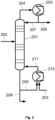
- the plant comprises a reactive distillation column 201.
- a solution of a lower metal alcoholate is fed into this via line 202.
- a higher alcohol is fed into the bottom circulation via line 203 and the evaporator 210.
- a vapor comprising lower alcohol is withdrawn via line 204 and condensed in condenser 205.
- a first partial stream of the condensed vapor is discharged from the process via line 206, while a second partial stream of the condensed vapor is returned to the top of the column via line 207.
- a solution of a higher metal alcoholate in the higher alcohol is withdrawn.
- a first partial stream of the solution of the higher metal alcoholate is discharged from the process via line 208, while a second partial stream of the solution of the higher metal alcoholate is returned to the bottom of the column via the evaporator 210 together with the higher alcohol from line 203 via line 211.
- the sample was mixed with 1 mL of tap water, sealed with an aluminum cap and analyzed by headspace GC (separation column DB-1, length 30 m, Inner diameter 0.25 mm, film thickness 1.0 ⁇ m). Quantification was carried out using the standard addition method. The detection limit was less than 100 mg/kg.
- a multiple determination of the sample is carried out, for example a double determination.
- a specific amount of the substance to be determined (the higher alcohol) is added to each sample several times and the sample is measured after each addition.
- the increase in the substance signal is determined.
- the concentration of the higher alcohol in the original sample can be calculated by linear regression.
- the solubility of the samples must be checked in advance. If two phases form, the sample weight must be reduced.
- the examples were carried out in a system that included a glass bubble-cap column with 80 trays and a forced circulation flash evaporator.
- Tables 1A and 1B show the specific parameters of the examples.
- the evaporator was heated with a commercially available thermostat (Julabo HT6) with a maximum heating power of 5700 W.
- the diameter of the column was 50 mm.
- Sodium methoxide (30 wt.% in methanol) was fed into the side of the column. To avoid heat losses, the column was heated isothermally with an electric protective heater.
- the higher alcohol was fed into the column either before the evaporator or onto a tray in the stripping section or together with sodium methoxide from the side.
- the amount of higher metal alcoholate or methanol in the solution of the higher metal alcoholate withdrawn at the bottom was determined.
- the vapor was discharged from the top of the column and condensed in a condenser. The amount of higher alcohol in the top condensate was determined.
- Comparative example 1 was initially carried out as in example 1. After the steady state had been established, the feed of isopropanol upstream of the evaporator was stopped and isopropanol was instead fed in together with sodium methoxide. The composition of the top condensate or the sodium isopropoxide withdrawn at the bottom was determined after the steady state had been established again.
- Comparative example 2 was initially carried out in the same way as example 2. After the steady state had been established, the feed of sec-butanol upstream of the evaporator was stopped and sec-butanol was instead fed in together with sodium methoxide. The composition of the top condensate or the sodium sec-butoxide withdrawn at the bottom was determined after the steady state had been established again.
- Comparative Example 3 was carried out analogously to Example 5, with the difference that the 2-methyl-2-butanol was not fed in before the evaporator, but together with sodium methoxide on tray 30. The composition of the top condensate or of the sodium 2-methyl-2-butoxide withdrawn at the bottom was determined after the steady state had been established.
- Table 1A Experimental data for Examples 1 and 2 and Comparative Examples 1 and 2.
- Example 1 From the comparison of Example 1 with Comparative Example 1, it is evident that feeding the higher alcohol upstream of the evaporator results in a lower methanol concentration in the bottom than feeding the higher alcohol together with the lower alcoholate at tray 40 of the column at the same feed to reflux ratio.
- Table 2 Specific heating output Example 2 Comparison example 2, variant 4 Example 5, Variant 2 Comparison example 3, variant 1 Methanol in the bottoms [wt.%] 0.07 0.1 0.76 0.82 Oil temperature flow [°C] 120.1 122.8 122.5 127.7 Oil temperature return [°C] 115.4 117.6 117.5 121.2 ⁇ T flow / return [°C] 4.7 5.2 5 6.5 Oil mass flow [kg/h] 331.0 322.3 319.1 190.1 Heating capacity evaporator [W] 752 810 771 597 specific heating power [J/g] 10.1 10.9 18.0 25.2
Landscapes
- Chemical & Material Sciences (AREA)
- Organic Chemistry (AREA)
- Chemical Kinetics & Catalysis (AREA)
- Organic Low-Molecular-Weight Compounds And Preparation Thereof (AREA)
Description
- Metallalkoholate werden als starke Basen in der Synthese zahlreicher Chemikalien eingesetzt, beispielsweise bei der Herstellung von Wirkstoffen für die Pharma- bzw. Agrarindustrie. Metallalkoholate finden außerdem Anwendung als Katalysatoren in Umesterungs- und Amidierungsreaktionen.
- Metallalkoholate (MOR) können gemäß folgender Reaktionsgleichung aus Metallhydroxiden (MOH) und Alkoholen (ROH), die in einer Reaktivdestillationskolonne im Gegenstrom geführt werden, hergestellt werden, wobei bei der Reaktion anfallendes Wasser mit dem Destillat entfernt wird:
MOH + ROH MOR + H2O
- Die
EP 0 091 425 A1 beschreibt ein solches Verfahren, wobei ein wässriges Alkalimetallhydroxid in den Verstärkungsteil und ein gasförmiger Alkohol in den Sumpf der Kolonne eingeführt wird. Wasser wird über den Kopf der Kolonne als Azeotrop ausgeführt und einer Auftrennung unterzogen. Ähnliche Verfahren sind in derEP 1 997 794 A1 und derDD 246 988 A1 - Metallalkoholate können auch mittels Umalkoholisieren gemäß folgender Formel hergestellt werden, wobei Alkoholate niedrigsiedender Alkohole (MOR1) mit einem höhersiedenden Alkohol (R2OH) mittels Reaktivdestillation zu Alkoholaten höhersiedender Alkohole und niederen Alkoholen umgesetzt werden:
MOR1 + R2OH MOR2 + R1OH
- Ein solches Verfahren ist beispielsweise in der
DE 27 26 491 sowie derDE 1 254 612 beschrieben. Dabei wird ein Gemisch des höhersiedenden Alkohols und des Alkoholats des niedrigsiedenden Alkohols in die Kolonne eingespeist. - Die bekannten Verfahren zur Herstellung von Metallalkoholaten höhersiedender Alkohole, wie Isopropanol oder tert-Butanol, weisen einen hohen Energieaufwand auf. Die Aufgabe der vorliegenden Erfindung liegt in der Bereitstellung eines Verfahrens zur Herstellung von Metallalkoholaten mit vermindertem Energiebedarf.
- Die Aufgabe wird gelöst durch ein Verfahren zur Herstellung von Metallalkoholaten mittels Umalkoholisieren, wobei man
- ein niederes Metallalkoholat über einen seitlichen Zulauf in eine Reaktivdestillationskolonne mit oberhalb des Zulaufs gelegenem Verstärkungsteil und unterhalb des Zulaufs gelegenem Abtriebsteil einspeist;
- einen höheren Alkohol in den Abtriebsteil, den Sumpf und/oder einen Sumpfumlauf der Kolonne einspeist;
- am Sumpf der Kolonne und/oder aus dem Sumpfumlauf, vorzugsweise nach dem Verdampfer, eine Lösung eines höheren Metallalkoholats im höheren Alkohol abzieht; und
- am Kopf der Kolonne einen niederen Alkohol umfassenden Brüden abzieht, den Brüden zumindest teilweise kondensiert und einen Teilstrom des Kondensats als Rücklauf auf den Kopf der Kolonne zurückführt;
- Im erfindungsgemäßen Verfahren werden das niedere Metallalkoholat und der höhere Alkohol umalkoholisiert, um das höhere Metallalkoholat und den niederen Alkohol zu erhalten. Am Kopf der Reaktivdestillationskolonne wird ein niederen Alkohol umfassender Brüden und am Sumpf der Kolonne und/oder aus dem Sumpfauslauf eine Lösung des höheren Metallalkoholats im höheren Alkohol abgezogen. Es werden also eine gasförmige und eine flüssige Fraktion abgezogen. Der Reinheitsgrad der erhaltenen Fraktionen ist entscheidend für die Effizienz des Verfahrens und die Verwertbarkeit der Fraktionen.
- Der am Kopf der Kolonne abgezogene Brüden wird zumindest teilweise kondensiert und ein Teilstrom des erhaltenen Kondensats wird als Rücklauf auf den Kopf der Kolonne zurückgeführt. In der Kolonne stehen eine Gasphase und eine flüssige Phase miteinander in Kontakt, die im Gegenstrom zueinander geführt werden. Es findet ein Stoffaustausch zwischen der Gasphase und der flüssigen Phase statt. Dabei reichern sich die leichter flüchtigen Anteile in Richtung des Kopfs der Kolonne in der Gasphase und die schwerer flüchtigen Anteile in Richtung des Sumpfs der Kolonne in der flüssigen Phase an.
- Der Reinheitsgrad insbesondere der am Sumpf und/oder aus dem Sumpfumlauf abgezogenen Lösung des höheren Metallalkoholats kann unter anderem über das Rücklaufverhältnis am Kopf der Kolonne eingestellt werden. In der Regel bedingt ein größeres Rücklaufverhältnis einen höheren Reinheitsgrad der Lösung des höheren Metallalkoholats.
- Es wurde gefunden, dass das Einspeisen des höheren Alkohols unterhalb des Zulaufs des niederen Metallalkoholats eine signifikant niedrigere Kontamination der Lösung des höheren Metallalkoholats mit niederem Alkohol bedingt. Um die gewünschten Spezifikationen zu erreichen, wird im erfindungsgemäßen Verfahren also ein niedrigeres Rücklaufverhältnis und ein verringerter Sumpfumlauf benötigt. Vorteilhafterweise weist das erfindungsgemäße Verfahren bei gleicher Trennaufgabe somit einen signifikant niedrigeren Energiebedarf auf.
- Die Bezeichnung "niederer" und "höherer" Alkohol bedeutet niedriger siedender Alkohol und höher siedender Alkohol. Es versteht sich, dass im erfindungsgemäßen Verfahren der höhere Alkohol ("Umalkoholisierungsalkohol") einen höheren Siedepunkt aufweist als der Alkohol des niederen Metallalkoholats. Das erfindungsgemäße Verfahren ist allgemein anwendbar auf die Umsetzung von Metallalkoholaten niederer Alkohole mit höheren Alkoholen, soweit eine Destillierbarkeit der Alkohole gegeben ist und das Löslichkeitsverhalten der niederen und höheren Metallalkoholate die Umsetzung in flüssiger Phase zulassen.
- Das niedere Metallalkoholat wird über einen seitlichen Zulauf in die Reaktivdestillationskolonne eingespeist. Unter der Bezeichnung "seitlich" wird verstanden, dass die Einspeisung unterhalb des Kolonnenkopfes und oberhalb des Kolonnensumpfes erfolgt. Der Ort des Zulaufs des niederen Metallalkoholats trennt die Kolonne in einen Verstärkungsteil (oberhalb des Zulaufs) und einen Abtriebsteil (unterhalb des Orts des Zulaufs). Die Umalkoholisierung findet im Abtriebsteil der Kolonne statt.
- Üblicherweise speist man das niedere Metallalkoholat als Lösung in dem niederen Alkohol ein, wobei die Lösung 20 bis 40 Gew.-% des niederen Metallalkoholats umfasst, bevorzugt 25 bis 35 Gew.-% des niederen Metallalkoholats, wie 28 bis 32 Gew.-% des niederen Metallalkoholats, bezogen auf das Gesamtgewicht der Lösung des niederen Metallalkoholats.
- Das niedere Metallalkoholat ist üblicherweise ein Metallalkoholat eines einwertigen C1-C4-Alkohols, also Methanolat, Ethanolat, Propanolat, Butanolat und deren Konstitutionsisomeren, einschließlich cyclischer Alkoholate. Besonders bevorzugt ist das niedere Metallalkoholat Metallmethanolat oder Metallethanolat, insbesondere Metallmethanolat.
- Das niedere Metallalkoholat ist üblicherweise ein Alkalimetallalkoholat, bevorzugt ein Natriumalkoholat oder ein Kaliumalkoholat.
- Besonders bevorzugt ist das niedere Metallalkoholat Natriummethanolat oder Kaliummethanolat, insbesondere Natriummethanolat.
- Die Temperatur der Lösung des niederen Metallalkoholats am seitlichen Zulauf wird geeigneter Weise so gewählt, dass das niedere Metallalkoholat stets in Lösung bleibt. Die Temperatur der Lösung des niederen Metallalkoholats beträgt vorzugsweise mindestens 6 °C, insbesondere mindestens 10 °C und besonders bevorzugt mindestens 20 °C, beispielsweise 25 °C oder 30 °C. Die Lösung des niederen Metallalkoholats kann bis zur Siedetemperatur vorgeheizt werden, beispielsweise in einem Wärmetauscher, in dem gleichzeitig die am Sumpf der Kolonne abgezogene Lösung des höheren Metallalkoholats abgekühlt wird. Dies ist energetisch besonders vorteilhaft.
- In den Abtriebsteil, den Sumpf und/oder einen Sumpfumlauf der Reaktivdestillationskolonne wird ein höherer Alkohol eingespeist, vorzugsweise in den Sumpf und/oder den Sumpfumlauf. Der höhere Alkohol kann in flüssiger Form oder gasförmig in den Abtriebsteil, den Sumpf oder Sumpfumlauf der Kolonne eingespeist werden. Vorzugsweise wird der höhere Alkohol in flüssiger Form in den Abtriebsteil, den Sumpf und/oder Sumpfumlauf der Kolonne eingespeist. Besonders bevorzugt wird der höhere Alkohol in flüssiger Form in den Sumpf und/oder Sumpfumlauf, insbesondere den Sumpfumlauf der Kolonne eingespeist.
- Die Reaktivdestillationskolonne weist üblicherweise einen Verdampfer auf, vorzugsweise einen Umlaufverdampfer. Im Verdampfer wird ein Teilstrom der am Sumpf der Kolonne abgezogenen Lösung des höhersiedenden Metallalkoholats erhitzt und zumindest teilweise gasförmig zurück in den Sumpf der Kolonne geführt. Alternativ oder zusätzlich wird der Sumpf direkt beheizt. Ein Teil des höheren Alkohols liegt in der Reaktivdestillationskolonne gasförmig vor und steigt Richtung Kopf der Kolonne auf.
- Der höhere Alkohol ist üblicherweise ausgewählt unter einwertigen C2-C10-Alkoholen, also Ethanol, Propanol, Butanol, Pentanol, Hexanol, Heptanol, Octanol, Nonanol, Decanol und deren Konstitutionsisomeren, einschließlich cyclischer Alkohole. Grundsätzlich können auch mehrwertige C2-C10-Alkohole wie Diole, beispielsweise Ethylenglycol, Diethylenglycol, Propandiol oder Butandiol, verwendet werden. Besonders bevorzugt ist der höhere Alkohol ausgewählt unter Isopropanol, sec-Butanol, 2-Methyl-2-butanol, tert-Butanol, 2-Methyl-2-pentanol, 3-Methyl-3-pentanol, 3-Ethyl-3-pentanol, 2-Methyl-2-hexanol und 3-Methyl-3-hexanol. Ganz besonders bevorzugt sind Isopropanol, 2-Methyl-2-butanol, 3-Methyl-3-pentanol und 3-Ethyl-3-pentanol, insbesondere Isopropanol und 2-Methyl-2-butanol.
- Am Sumpf der Kolonne und/oder aus dem Sumpfumlauf wird eine Lösung des höheren Metallalkoholats im höheren Alkohol abgezogen. Die abgezogene Lösung des höheren Metallalkoholats weist vorteilhafterweise nur geringe Mengen an niederem Alkohol auf, was ein effizientes Verfahren erlaubt. Bevorzugt umfasst die Lösung des höheren Metallalkoholats höchstens 1,0 Gew.-% des niederen Alkohols, besonders bevorzugt höchstens 0,5 Gew.-% des niederen Alkohols und ganz besonders bevorzugt höchstens 0,3 Gew.-% des niederen Alkohols, beispielsweise 0,01 bis 0,20 Gew.-% des niederen Alkohols oder 0,01 bis 0,10 Gew.-% des niederen Alkohols, bezogen auf das Gesamtgewicht abgezogenen Lösung des höheren Metallalkoholats. Die Methanol-Konzentration in der Lösung des höheren Metallalkoholats kann beispielsweise mittels Dampfraumanalyse oder mittels Gaschromatographie erfolgen.
- Die Lösung des höheren Metallalkoholats umfasst üblicherweise 3 bis 60 Gew.-% des höheren Metallalkoholats, bevorzugt 5 bis 55 Gew.-% und besonders bevorzugt 7 bis 50 Gew.-% des höheren Metallalkoholats, beispielsweise 7 bis 30 Gew.-%, 7 bis 25 Gew.-%, 7 bis 20 Gew.-% oder 7 bis 15 Gew.-% des höheren Metallalkoholats, bezogen auf das Gesamtgewicht der abgezogenen Lösung des höheren Metallalkoholats. Die Konzentration des höheren Metallalkoholats in der Lösung des höheren Metallalkoholats kann beispielsweise mittels Titration bestimmt werden.
- Am Kopf der Kolonne wird ein niederen Alkohol umfassender Brüden abgezogen. Der abgezogene Brüden besteht im Wesentlichen aus niederem Alkohol und weist vorteilhafterweise nur geringe Mengen an höherem Alkohol auf, was ein effizientes Verfahren erlaubt. Der Brüden wird zumindest teilweise kondensiert ("Kopfkondensat"), wobei das Kopfkondensat bevorzugt höchstens 1,0 Gew.-% des höheren Alkohols, besonders bevorzugt höchstens 0,6 Gew.-% des höheren Alkohols und ganz besonders bevorzugt höchstens 0,5 Gew.-% des höheren Alkohols, umfasst, bezogen auf das Gesamtgewicht des Kopfkondensats. Die Konzentration des höheren Alkohols im Kopfkondensat kann beispielsweise mittels Gaschromatographie bestimmt werden.
- Das niedere Metallalkoholat und der höhere Alkohol werden in einer Reaktivdestillationskolonne miteinander in Kontakt gebracht. Das Inkontaktbringen des niederen Metallalkoholats und des höheren Alkohols erfolgt dabei im Gegenstrom. Der höhere Alkohol liegt teilweise gasförmig vor und steigt in der Kolonne Richtung Kopf der Kolonne auf, während die Lösung des niederen Metallalkoholats Richtung des Sumpfs der Kolonne absinkt. Durch den Kontakt von Gasphase und flüssiger Phase werden der höhere Alkohol und das niedere Metallalkoholat umalkoholisiert, um das höhere Metallalkoholat und den niederen Alkohol zu erhalten.
- Als Reaktivdestillationskolonne kann eine übliche Reaktivdestillationskolonne verwendet werden. Die Kolonne ist beispielweise ausgewählt unter Füllkörper-, Packungs- und Bodenkolonnen, besonders bevorzugt Boden- und Packungskolonnen.
- In geeigneten Bodenkolonnen sind Sieb-, Glocken- oder Ventilböden eingebaut, über welche die flüssige Phase strömt. Die Reaktivdestillationskolonne des erfindungsgemäßen Verfahrens weist vorzugsweise Böden als Einbauten auf, beispielsweise ausgewählt unter Glockenböden, Ventilböden, Tunnelböden und Thormann®-Böden.
- Füllkörperkolonnen können mit unterschiedlichen Formkörpern gefüllt werden. Wärme- und Stoffaustausch werden durch die Vergrößerung der Oberfläche aufgrund der meist etwa 25 bis 80 mm großen Formkörper verbessert. Bekannte Beispiele sind der Raschig-Ring (ein Hohlzylinder), Pall-Ring, Hiflow-Ring, Intalox-Sattel und dergleichen. Die Füllkörper können geordnet, aber auch regellos (als Schüttung) in die Kolonne eingebracht werden. Als Materialien kommen Glas, Keramik, Metall und Kunststoffe in Frage.
- Strukturierte Packungen sind eine Weiterentwicklung der geordneten Füllkörper. Sie weisen eine regelmäßig geformte Struktur auf. Dadurch ist es bei Packungen möglich, Druckverluste bei der Gasströmung zu reduzieren. Es gibt verschiedene Ausführungen von Packungen, z. B. Gewebe- oder Blechpackungen.
- Vorzugsweise umfasst der Verstärkungsteil der Kolonne Packungen, während der Abtriebsteil der Kolonne Böden umfasst.
- Als Kopf der Kolonne wird der von Einbauten freie Bereich oberhalb des obersten Bodens bzw. oberhalb der obersten Packungsschicht bezeichnet. Er wird in der Regel von einem gewölbten Boden (Haube, z. B. Klöpperboden oder Korbbogenboden) gebildet, welcher das Abschlusselement der Reaktivdestillationskolonne bildet.
- Als Sumpf der Kolonne wird der von Einbauten freie Bereich unterhalb des untersten Bodens bzw. unterhalb der untersten Packungsschicht bezeichnet.
- Die geeignete Anzahl der theoretischen Trennstufen im Verstärkungsteil hängt von der Differenz der Dampfdrücke des höheren und des niederen Alkohols ab, wobei bei einer geringeren Differenz eine höhere Anzahl theoretischer Trennstufen vorteilhaft ist. Die geeignete Anzahl der theoretischen Trennstufen im Abtriebsteil hängt von der Differenz der Dampfdrücke des höheren und des niederen Alkohols sowie der Gleichgewichtslage der Reaktion ab, wobei eine höhere Anzahl theoretischer Trennstufen vorteilhaft ist, je stärker das Gleichgewicht auf Seiten der Edukte liegt. Die geeignete Anzahl der theoretischen Trennstufen sowohl im Verstärkungs- als auch im Abtriebsteil hängt außerdem vom zu erreichenden Reinheitsgrad von Sumpf- und Kopfprodukt und der verwendeten Rücklaufmenge ab, wobei eine höhere Anzahl theoretischer Trennstufen zum Erreichen einer höheren Reinheit bei gegebener Rücklaufmenge benötigt wird.
- Die Kolonne kann aus mehreren kaskadenartig hintereinander geschalteten Einzelgefäßen bzw. Einzelkolonnen bestehen. Die Einzelgefäße bzw. Einzelkolonnen sind vorzugsweise übereinander angeordnet und können gegebenenfalls seitlich gegeneinander versetzt sein. In einer weiteren Ausführungsform sind die Einzelgefäße bzw. Einzelkolonnen unter Verwendung geeigneter Pumpeinrichtungen nebeneinander angeordnet.
- In beiden Fällen muss durch entsprechende Verbindungsleitungen und gegebenenfalls Transporteinrichtungen sichergestellt werden, dass Abtriebs- und Verstärkungsteil direkt miteinander gekoppelt sind und sich der Rückfluss des Verstärkungsteils in vorteilhafter Weise auf die im Abtriebsteil stattfindende Umalkoholisierung auswirken kann. Bevorzugt sind der Reaktions- und der Verstärkungsteil in einer einzigen Kolonne übereinander angeordnet.
- Der am Kopf der Kolonne abgezogene, niederen Alkohol umfassende Brüden wird zumindest teilweise kondensiert, wobei ein Kopfkondensat erhalten wird. Die Kondensation erfolgt vorzugsweise in einem oder mehreren in Serie geschalteten Platten- oder Rohrbündelkondensatoren oder Luftkühlern. Vorzugsweise verwendet man Luftkühler oder Rohrbündelkondensatoren oder Kombinationen davon. Die Kühlung der Kondensatoren kann je nach Bauart beispielsweise mittels Luft, Kühlwasser oder Sole erfolgen.
- Vorzugsweise wird der Brüden im Wesentlichen vollständig kondensiert, beispielsweise zu mehr als 98 Gew.-% oder mehr als 99 Gew.-%, bezogen auf die Gesamtmenge des Brüdens.
- Ein Teilstrom des erhaltenen Kondensats wird als Rücklauf auf den Kopf der Kolonne zurückführt. Das Rücklaufverhältnis beeinflusst die Reinheit der abgezogenen gasförmigen Fraktion und insbesondere der abgezogenen flüssigen Fraktion. Unter dem Rücklaufverhältnis wird das Verhältnis des Teilstroms des Kondensats (kg/h), der in die Kolonne zurückgeführt wird (Rücklauf), und des Teilstroms des Kondensats (kg/h), der aus dem Verfahren ausgeführt wird, verstanden.
- Die genannten Rücklaufverhältnisse sind auf die Verwendung einwertiger, aliphatischer oder cycloaliphatischer höherer Alkohole gerichtet. Bei anderen höheren Alkoholen, z. B. bei zwei- oder mehrwertigen Alkoholen oder bei andern als aliphatischen oder cycloaliphatischen Alkoholen, kann die Rücklaufmenge gegebenenfalls höher sein. Die optimale Rücklaufmenge wird zweckmäßig in Vorversuchen ermittelt.
- Das optimale Rücklaufverhältnis für das erfindungsgemäße Verfahren wird in bekannter Weise so festgelegt, dass bei einem wirtschaftlichen Optimum hinsichtlich der aufzuwendenden Leistung zur Trennung des im System vorhandenen niederen und höheren Alkohols ein Optimum hinsichtlich der Reinheit des am Kopf abzuführenden niederen Alkohols bzw. der am Sumpf abzuziehenden Lösung des höheren Alkoholats im höheren Alkohol erreicht wird.
- Der am Kopf abgezogene niedere Alkohol, also der ausgeführte Teilstrom des Kopfkondensats, ist in der Regel von hoher Reinheit und kann ohne weitere Destillation wiederverwendet werden. Es wird nur der überschüssige Teil des Kopfkondensats aus dem System ausgeführt, der zur Einstellung der Rückflussmenge nicht benötigt wird. Der übrige Teil des Kopfkondensats wird als Rücklauf auf den Kopf der Kolonne zurückführt.
- Die Reaktivdestillationskolonne weist üblicherweise einen Sumpfumlauf auf. In einer Ausführungsform wird dabei ein Teilstrom der am Sumpf der Kolonne abgezogenen Lösung des höheren Metallalkoholats im höheren Alkohol in den Sumpf der Kolonne zurückgeführt, während ein weiterer Teilstrom der am Sumpf der Kolonne abgezogenen Lösung des höheren Metallalkoholats im höheren Alkohol aus dem Verfahren ausgeführt wird. In einer weiteren Ausführungsform wird ein Teilstrom aus dem Sumpfumlauf in den Sumpf der Kolonne zurückgeführt, während ein weiterer Teilstrom aus dem Sumpfumlauf, vorzugsweise nach dem Verdampfer, entnommen und aus dem Verfahren ausgeführt wird.
- Die Reaktivdestillationskolonne weist einen Verdampfer auf, der im Kolonnensumpf integriert ist, oder vorzugsweise einen in einen Sumpfumlauf aufgenommenen Verdampfer. Ein Teilstrom der am Sumpf der Kolonne abgezogenen Lösung des höheren Metallalkoholats wird über einen Sumpfumlauf dem Verdampfer zugeführt und anschließend als erhitzter, ggf. zwei-phasiger Fluidstrom in die Kolonne zurückgeführt. Geeignete Verdampfer sind z. B. Aufkocher, Naturumlaufverdampfer, Zwangsumlaufverdampfer und Zwangsumlaufentspannungsverdampfer.
- Bei Zwangsumlaufverdampfern wird eine Pumpe verwendet, um die zu verdampfende Flüssigkeit durch den Erhitzer zu führen. Das erhaltene Dampf/Flüssigkeitsgemisch wird dann in die Kolonne zurückgeführt.
- Bei Zwangsumlaufentspannungsverdampfern wird ebenfalls eine Pumpe verwendet, um die zu verdampfende Flüssigkeit durch den Erhitzer zu führen. Es wird ein überhitzter, flüssiger Rückführstrom erhalten, der in den Sumpf der Kolonne entspannt wird. Der Druck auf die aus der Kolonne abgezogene Lösung des Metallalkoholats, die zur Kolonne zurückgeführt wird, wird durch Überhitzen erhöht. Der überhitzte Rückführstrom wird über ein Durchflussbegrenzungsmittel entspannt. Hierdurch erfolgt eine Überhitzung der Flüssigkeit über ihren Siedepunkt in Bezug auf den Druck im Inneren der Kolonne.
- Beim Durchtritt der überhitzten Flüssigkeit durch das Durchflussbegrenzungsmittel und Wiedereintritt in die Kolonne erfolgt eine schlagartige Verdampfung der Flüssigkeit. Diese schlagartige Verdampfung verläuft unter erheblicher Volumenvergrößerung und führt zu einer Beschleunigung des in die Kolonne eintretenden Fluidstroms. Vorteilhafterweise ist das Durchflussbegrenzungsmittel unmittelbar vor dem Wiedereintritt der überhitzten Flüssigkeit in die Kolonne, oder sogar im Inneren dieser, angeordnet.
- Bevorzugt wird als Durchflussbegrenzungsmittel eine Blende, ein Ventil, eine Drossel, eine Lochscheibe, eine Düse, eine Kapillare oder Kombinationen davon, insbesondere ein Ventil, verwendet. Beispielsweise kann ein Drehkegelventil verwendet werden. Besonders bevorzugt ist es, wenn die Öffnungscharakteristik des Durchflussbegrenzungsmittels verstellbar ist. Auf diese Weise kann der Druck im Verdampfer auch bei geänderten Strömungsgeschwindigkeiten, wie sie beispielsweise bei An- und Abfahrvorgängen auftreten können, immer über dem Siededruck der Flüssigkeit, bezogen auf den Druck im Inneren der Kolonne, gehalten werden.
- Vorteilhaft ist es, dass durch Betrieb des Verdampfers als Zwangsumlauf bzw. als Zwangsumlaufentspannung eine gegenüber Betrieb mit Naturumlauf erhöhte Strömungsgeschwindigkeit der Flüssigkeit in der Erhitzungsvorrichtung, z. B. im Rohrbündel des Wärmetauschers, erzielt wird. Durch die erhöhte Strömungsgeschwindigkeit besteht ein verbesserter Wärmeübergang zwischen Wärmetauscher und erhitzter Flüssigkeit, der wiederum zur Vermeidung lokaler Überhitzungen beiträgt.
- Die bei Zwangsumlauf- bzw. Zwangsumlaufentspannungsverdampfern zu verwendende Pumpe wird bevorzugt zwischen der Entnahmeleitung und dem Verdampfer angeordnet.
- In einer bevorzugten Ausführungsform weist die Kolonne einen Zwangsumlaufverdampfer auf und man speist den höheren Alkohol in flüssiger Form in den Zulauf zum Zwangsumlaufverdampfer ein.
- Alternativ oder zusätzlich zum Sumpfumlaufverdampfer kann der Sumpf direkt beheizt werden, beispielsweise mittels eines Aufkochers.
- Die Sumpftemperatur der Reaktivdestillationskolonne bestimmt bei gegebenem Druck die Konzentration des höheren Metallalkoholats in der am Sumpf der Kolonne oder aus dem Sumpfumlauf abgezogenen Lösung. Die Temperatur und damit die Konzentration werden zweckmäßigerweise so gewählt, dass das höhere Metallalkoholat im Sumpf stets in Lösung bleibt. Die Sumpftemperatur wird beispielsweise über einen Verdampfer und/oder eine direkte Beheizung des Sumpfs eingestellt.
- Das erfindungsgemäße Verfahren kann sowohl unter Normaldruck als auch unter erhöhtem oder vermindertem Druck durchgeführt werden. Es ist vorteilhaft, die Reaktivdestillationskolonne bei einem Druck von 0,2 bis 10 bar absolut zu betreiben. Bevorzugt wird die Reaktivdestillationskolonne bei Umgebungsdruck, beispielsweise 1 bar absolut, betrieben.
- Die Gleichgewichtslage der Reaktion ist bei der Herstellung mancher Alkoholate temperaturabhängig. In diesen Fällen können hohe Temperaturen vorteilhafterweise einen höheren Umsatz bedingen. Es kann außerdem vorteilhaft sein, das erfindungsgemäße Verfahren unter erhöhtem Druck durchzuführen, wie beispielsweise mindestens 1,5 bar absolut, mindestens 2,5 bar absolut, oder mindestens 5,0 bar absolut.
- Das erfindungsgemäße Verfahren kann sowohl kontinuierlich als auch batchweise durchgeführt werden. Bevorzugt wird das erfindungsgemäße Verfahren kontinuierlich durchgeführt.
- Innerhalb der Reaktivdestillationskolonne wird durch den ständigen Stoffaustausch und die sich ändernden Konzentrationen innerhalb der Gasphase und der flüssigen Phase das Reaktionsgleichgewicht ständig neu eingestellt, was einen hohen Umsatz ermöglicht. Beim Anfahren der Kolonne kann zur Einstellung der Menge des Rückflusses des niederen Alkohols dieser dem Kolonnenkopf zugeführt werden, wobei der Abtriebsteil und der Sumpf mit dem höheren Alkohol gefüllt sind. Außerdem kann dem höheren Alkohol niederer Alkohol zugesetzt werden.
- Nach Erreichen der Betriebstemperatur wird dann die Lösung des niederen Metallalkoholats zugeführt. Während der Umsetzung bildet sich laufend neuer niederer Alkohol.
- In einer weiteren Ausführungsform wird die Reaktivdestillationskolonne vor dem Anfahren mit dem höheren Alkohol befüllt und dieser zunächst auch als Rückfluss eingesetzt. Nach Erreichen der Betriebstemperatur wird dann die Lösung des niederen Metallalkoholats zugeführt.
- Der am Kopf der Kolonne abgezogene Brüden bzw. dessen Kondensat besteht üblicherweise aus im Wesentlichen reinem niederem Alkohol. Das Kondensat kann ohne weitere Aufreinigung ausgeführt und beispielsweise der Herstellung von niederen Metallalkoholaten oder Lösungen davon zugeführt werden.
- Die am Sumpf der Kolonne und/oder aus dem Sumpfumlauf abgezogene Lösung des höheren Metallalkoholats besteht üblicherweise im Wesentlichen aus dem höheren Alkohol und dem höheren Metallalkoholat. Die Lösung des höheren Metallalkoholats kann daher als solche weiterverwendet werden, ggf. nach Abkühlen in einem Wärmetauscher.
- Alternativ kann der höhere Alkohol vom höheren Metallalkoholat abgetrennt werden. Dies kann durch Eindampfen erfolgen.
- Die Erfindung wird durch die beiliegenden Figuren und die nachstehenden Beispiele weiter veranschaulicht.
-
Fig. 1 zeigt eine zur Herstellung von Metallalkoholaten geeignete Vergleichsanlage. -
Fig. 2 zeigt eine zur Herstellung von Metallalkoholaten mittels des erfindungsgemäßen Verfahrens geeignete Anlage. - Gemäß
Fig. 1 umfasst die Anlage eine Reaktivdestillationskolonne 101. In diese wird über Leitung 102 eine Lösung eines niederen Metallalkoholats zusammen mit einem höheren Alkohol aus Leitung 103 eingespeist. - Am Kopf der Kolonne 101 wird über Leitung 104 ein niederen Alkohol umfassender Brüden abgezogen und in Kondensator 105 kondensiert. Ein erster Teilstrom des kondensierten Brüdens wird über Leitung 106 aus dem Verfahren ausgeführt, während ein zweiter Teilstrom des kondensierten Brüdens über Leitung 107 in den Kopf der Kolonne zurückgeführt wird.
- Am Sumpf der Kolonne wird eine Lösung eines höheren Metallalkoholats im höheren Alkohol abgezogen. Ein erster Teilstrom der Lösung des höheren Metallalkoholats wird über Leitung 108 aus dem Verfahren ausgeführt, während ein zweiter Teilstrom der Lösung des höheren Metallalkoholats über den Verdampfer 110 und Leitung 111 in den Sumpf der Kolonne zurückgeführt wird.
- Gemäß
Fig. 2 umfasst die Anlage eine Reaktivdestillationskolonne 201. In diese wird über Leitung 202 eine Lösung eines niederen Metallalkoholats eingespeist. Über Leitung 203 und den Verdampfer 210 wird ein höherer Alkohol in den Sumpfumlauf eingespeist. - Am Kopf der Kolonne 201 wird über Leitung 204 ein niederen Alkohol umfassender Brüden abgezogen und in Kondensator 205 kondensiert. Ein erster Teilstrom des kondensierten Brüdens wird über Leitung 206 aus dem Verfahren ausgeführt, während ein zweiter Teilstrom des kondensierten Brüdens über Leitung 207 in den Kopf der Kolonne zurückgeführt wird.
- Am Sumpf der Kolonne wird eine Lösung eines höheren Metallalkoholats im höheren Alkohol abgezogen. Ein erster Teilstrom der Lösung des höheren Metallalkoholats wird über Leitung 208 aus dem Verfahren ausgeführt, während ein zweiter Teilstrom der Lösung des höheren Metallalkoholats über den Verdampfer 210 gemeinsam mit dem höheren Alkohol aus Leitung 203 über Leitung 211 in den Sumpf der Kolonne zurückgeführt wird.
- Es wurden Versuche zur Herstellung von Natriumalkoholaten mittels Umalkoholisieren aus Natriummethanolat und höheren Alkoholen durchgeführt, wobei Isopropanol, 2-Butanol bzw. 2-Methyl-2-butanol als höhere Alkohole verwendet wurden.
- Zur Bestimmung des Gehalts an höherem Alkohol im Kopfkondensat wurde eine Probe entnommen, 1,4-Dioxan als interner Standard zugegeben und die Probe mittels Gaschromatographie hinsichtlich ihres Alkoholgehalts analysiert (Trennsäule RTX-5 Amin, Länge 30 m, Innendurchmesser 0,32 mm, Filmdicke 1,5 µm). Die Nachweisgrenze betrug ca. 500 mg/kg.
- Zur Bestimmung des Methanol-Gehalts im Sumpf der Kolonne wurden bei der Verwendung von Isopropanol als höherer Alkohol 150 mg, bei der Verwendung von 2-Butanol 60 mg einer Probe in ein 22,5 mL Headspace-Glas eingewogen.
- Die Probe wurde mit 1 mL Leitungswasser versetzt, mit einer Aluminiumkappe gasdicht verschlossen und per Headspace-GC analysiert (Trennsäule DB-1, Länge 30 m, Innendurchmesser 0,25 mm, Filmdicke 1,0 µm). Die Quantifizierung erfolgte mittels des Standard-Additionsverfahrens. Die Nachweisgrenze betrug weniger als 100 mg/kg.
- Beim Standard-Additionsverfahren wird eine Mehrfachbestimmung der Probe durchgeführt, beispielsweise eine Doppelbestimmung. Dabei wird jeder Probe mehrfach eine spezifische Menge der zu bestimmenden Substanz (des höheren Alkohols) hinzugefügt und die Probe nach jeder Zugabe gemessen. Der Zuwachs des Substanzsignals wird ermittelt. Die Konzentration des höheren Alkohols in der ursprünglichen Probe kann durch lineare Regression berechnet werden.
- Die Löslichkeit der Proben muss vorab geprüft werden. Bilden sich zwei Phasen aus, muss die Einwaage reduziert werden.
- Zur Bestimmung des Methanol-Gehalts im Sumpf der Kolonne wurden 500 mg einer Probe entnommen, welche man auf Raumtemperatur abkühlen ließ. Die Probe wurde mit 1 mL Wasser und 0,5 mg tert-Butanol in Dioxan (1 mL, als interner Standard) vermengt, mit einem Tropfen Phosphorsäure versetzt und mit 3 mL Dioxan (ohne internen Standard) verdünnt, um eine verdünnte Probe zu erhalten. Im Falle fester Proben wurden diese vor dem Vermischen mit Wasser, tert-Butanol, Phosphorsäure und Dioxan bei 60 °C aufgeschmolzen. Die verdünnte Probe wurde mittels Gaschromatographie hinsichtlich ihres Alkoholgehalts analysiert (Trennsäule DB-1, Länge 30 m, Innendurchmesser 0,25 mm, Filmdicke 1,0 µm). Die Nachweisgrenze betrug ca. 200 mg/kg.
- Zur Bestimmung des Alkoholats im Sumpf der Kolonne wurde eine Probe entnommen und mittels Titration in 2-Propanol mit Trifluormethansulfonsäure (0,1 mol/l in 2-Propanol) der Gesamtgehalt an Basen bestehend aus Alkoholat, Hydroxiden und Carbonat bestimmt. Die Menge an Hydroxiden und Carbonat wurde mittels volumetrischer Karl-Fischer-Titration (KFT) bestimmt, da diese Bestandteile in der KFT mit den KF-Komponenten reagieren und Wasser bilden. Der Beitrag von Hydroxiden und Carbonaten wird vom Gesamtgehalt an Basen subtrahiert, um den Gehalt an Alkoholat zu ermitteln.
- Die Beispiele wurden in einer Anlage durchgeführt, welche eine Glockenbodenkolonne aus Glas mit 80 Böden und einem Zwangsumlaufentspannungsverdampfer umfasste. In den Tabellen 1A und 1B sind die spezifischen Parameter der Beispiele gezeigt. Der Verdampfer wurde mit einem handelsüblichen Thermostat (Julabo HT6) mit einer maximalen Heizleistung von 5700 W beheizt. Der Durchmesser der Kolonne betrug 50 mm. Natriummethanolat (30 Gew.-% in Methanol) wurde seitlich in die Kolonne eingespeist. Zur Vermeidung von Wärmeverlusten wurde die Kolonne mit einer elektrischen Schutzheizung isotherm beheizt.
- Der höhere Alkohol wurde entweder vor dem Verdampfer oder auf einen Boden im Abtriebsteil oder zusammen mit Natriummethanolat seitlich in die Kolonne eingespeist. Die Menge an höherem Metallalkoholat bzw. Methanol in der am Sumpf abgezogenen Lösung des höheren Metallalkoholats wurde bestimmt.
- Am Kopf der Kolonne wurde der Brüden ausgeführt und in einem Kondensator kondensiert. Die Menge an höherem Alkohol im Kopfkondensat wurde bestimmt.
- Vergleichsbeispiel 1 wurde zunächst wie Beispiel 1 durchgeführt. Nach Einstellung des stationären Zustandes wurde die Einspeisung von Isopropanol vor dem Verdampfer eingestellt und Isopropanol stattdessen zusammen mit Natriummethanolat eingespeist. Die Zusammensetzung des Kopfkondensats bzw. des am Sumpf abgezogenen Natriumisopropanolats wurde nach erneutem Einstellen des stationären Zustandes bestimmt.
- Vergleichsbeispiel 2 wurde zunächst wie Beispiel 2 durchgeführt. Nach Einstellung des stationären Zustandes wurde die Einspeisung von sec-Butanol vor dem Verdampfer eingestellt und sec-Butanol stattdessen zusammen mit Natriummethanolat eingespeist. Die Zusammensetzung des Kopfkondensats bzw. des am Sumpf abgezogenen Natrium-sec-butanolats wurde nach erneutem Einstellen des stationären Zustandes bestimmt.
- Vergleichsbeispiel 3 wurde analog zu Beispiel 5 durchgeführt, mit dem Unterschied, dass die Einspeisung von 2-Methyl-2-butanol nicht vor dem Verdampfer, sondern zusammen mit Natriummethanolat auf Boden 30 erfolgte. Die Zusammensetzung des Kopfkondensats bzw. des am Sumpf abgezogenen Natrium-2-methyl-2-butanolats wurde nach Einstellen des stationären Zustandes bestimmt.
Tabelle 1A: Experimentelle Versuchsdaten zu Beispielen 1 und 2 sowie Vergleichsbeispielen 1 und 2. Beispiel 1 Vergleichsbeispiel 1 Beispiel 2 Vergleichsbeispiel 2 Variante 1 Variante 2 Variante 3 Variante 4 Höherer Alkohol Isopropanol 2-Butanol Zulauf Na-Methanolat [kg/h] 0,23 0,23 0,49 0,49 0,49 0,49 0,49 Zulaufstelle Na-Methanolat Boden 40 Boden 40 Boden 30 Boden 30 Boden 30 Boden 30 Boden 30 Zulauf des höheren Alkohols [kg/h] 1,226 1,125 1,814 1,742 1,800 1,874 1,918 Zulaufstelle des höheren Alkohols Vor Verdampfer Boden 40 Vor Verdampfer Boden 30 Boden 30 Boden 30 Boden 30 Kopfabzug [kg/h] 0,171 0,180 0,427 0,420 0,418 0,424 0,428 Sumpfabzug [kg/h] 1,286 1,172 1,869 1,809 1,871 1,94 1,977 Sumpfumlauf [kg/h] 150 150 150 150 150 150 150 Rücklauf [kg/h] 1,341 1,343 0,700 0,700 0,835 0,900 1,001 Rücklaufverhältnis 7,84 7,46 1,64 1,67 2,00 2,12 2,34 Verhältnis Zulauf / Rücklauf 0,172 0,171 0,700 0,700 0,587 0,544 0,4905 T (Kolonnenkopf) [°C] 63,0 62,2 62,2 62,6 62,1 62,2 62,3 T (Kolonnensumpf) [°C] 83,8 83,8 103 103 103 103 103 T (Zulauf) [°C] 47,9 54,5 52,5 54,0 54,0 54,0 54,5 Kopfdruck [mbar, absolut] 949 949 949,5 949,5 949,5 949,6 949,4 Differenzdruck der Kolonne [mbar] 81,3 82,2 73,8 76,2 78,2 79,8 82,5 Alkoholat im Sumpf [Gew.-%] 7,8 9,2 14,4 14,5 14,1 13,5 13,5 Methanol im Sumpf [Gew.-%] 0,04 2,0 0,07 0,7 0,4 0,2 0,1 Höherer Alkohol im Kopfkondensat [Gew.-%] 0,15 0,4 0,360 1,04 n.n. * n.n. * n.n. * * n.n.: unterhalb der Nachweisgrenze Tabelle 1B: Experimentelle Versuchsdaten zu Beispielen 3 bis 5 sowie Vergleichsbeispiel 3. Beispiel 3 Beispiel 4 Beispiel 5 Vergleichsbeispiel 3 Variante 1 Variante 2 Variante 3 Variante 1 Variante 2 Höherer Alkohol 2-Butanol 2-Methyl-2-Butanol Zulauf Na-Methanolat [kg/h] 0,49 0,49 0,15 0,225 0,10 0,15 0,10 Zulaufstelle Na-Methanolat Boden 30 Boden 30 Boden 30 Boden 30 Boden 30 Boden 30 Boden 30 Zulauf des höheren Alkohols [kg/h] 1,864 1,861 1,036 1,23 0,531 0,469 0,325 Zulaufstelle des höheren Alkohols Vor Verdampfer Boden 15 Vor Verdampfer Vor Verdampfer Vor Verdampfer Boden 30 Boden 30 Kopfabzug [kg/h] 0,430 0,432 0,139 0,187 0,091 0,099 0,068 Sumpfabzug [kg/h] 1,912 1,916 1,057 1,278 0,569 0,511 0,342 Sumpfumlauf [kg/h] 150 150 150 150 150 150 150 Rücklauf [kg/h] 0,860 0,840 0,835 1,000 1,000 1,330 1,000 Rücklaufverhältnis 2,00 1,94 7,19 5,35 14,62 10,10 19,56 Verhältnis Zulauf / Rücklauf 0,570 0,583 0,150 0,225 0,075 0,150 0,075 T (Kolonnenkopf) [°C] 62,4 62,3 62,7 63 62,6 62,3 62,3 T (Kolonnensumpf) [°C] 103 103 103,7 104,2 104,5 106,5 106,5 T (Zulauf) [°C] 50,3 50,0 47,4 49,9 47,7 52,2 51 Kopfdruck [mbar, absolut] 949,5 949,5 949,3 949,3 949,1 949,8 949,9 Differenzdruck der Kolonne [mbar] 78,7 78,2 81,8 83,7 88,9 80,6 88,1 Alkoholat im Sumpf [Gew.-%] 13,4 13,4 9,6 12,1 10,1 16,7 17,4 Methanol im Sumpf [Gew.-%] 0,012 0,09 0,27 0,76 0,04 0,82 0,16 Höherer Alkohol im Kopfkondensat [Gew.-%] 0,3 n.n.* 8,85 1,19 6,28 n.n.* n.n. * * n.n.: unterhalb der Nachweisgrenze - Aus dem Vergleich von Beispiel 1 mit Vergleichsbeispiel 1 ist ersichtlich, dass das Einspeisen des höheren Alkohols vor dem Verdampfer gegenüber dem gemeinsamen Einspeisen des höheren Alkohols mit dem niederen Alkoholat auf Boden 40 der Kolonne bei gleichem Verhältnis von Zulauf zu Rücklauf eine niedrigere Methanol-Konzentration im Sumpf bewirkt.
- Aus dem Vergleich von Beispiel 2 mit Vergleichsbeispiel 2 (Variante 1) ist wiederum ersichtlich, dass das Einspeisen des höheren Alkohols vor dem Verdampfer gegenüber dem gemeinsamen Einspeisen des höheren Alkohols mit dem niederen Alkoholat auf Boden 30 der Kolonne bei gleichem Verhältnis von Zulauf zu Rücklauf eine niedrigere Methanol-Konzentration im Sumpf bewirkt. Selbst bei einer Erhöhung des Rücklaufs in Varianten 2 bis 4 des Vergleichsbeispiels 2 von 0,7 kg/h auf 1,0 kg/h sinkt die Methanol-Konzentration im Sumpf lediglich auf 0,1 Gew.-%, gegenüber 0,07 Gew.-% in Beispiel 2.
- In Beispiel 3 wurde der höhere Alkohol vor dem Verdampfer eingespeist. In Beispiel 4 wurde der höhere Alkohol im Abtriebsteil auf Boden 15 eingespeist. In Vergleichsbeispiel 2 (Variante 2) wurde der höhere Alkohol zusammen mit dem niederen Alkoholat auf Boden 30 eingespeist. Die Rücklaufverhältnisse waren bei diesen drei Versuchen vergleichbar. Es ist ersichtlich, dass die Methanol-Konzentration im Sumpf in Beispiel 3 und 4 signifikant geringer war als in Vergleichsbeispiel 2 (Variante 2). Dies zeigt, dass das Einspeisen des höheren Alkohols vor dem Verdampfer oder im Abtriebsteil der Kolonne gegenüber dem gemeinsamen Einspeisen des höheren Alkohols mit dem niederen Alkoholat auf Boden 30 der Kolonne bei gleichem Verhältnis von Zulauf zu Rücklauf eine niedrigere Methanol-Konzentration im Sumpf bewirkt. Besonders vorteilhaft ist das Einspeisen des höheren Alkohols vor dem Verdampfer.
- Aus dem Vergleich von Beispiel 5, Variante 1 mit Vergleichsbeispiel 3, Variante 1 ist ersichtlich, dass das Einspeisen des höheren Alkohols vor dem Verdampfer gegenüber dem gemeinsamen Einspeisen des höheren Alkohols mit dem niederen Alkoholat auf Boden 30 der Kolonne bei gleichem Verhältnis von Zulauf zu Rücklauf eine niedrigere Methanol-Konzentration im Sumpf bewirkt. Dies ist auch aus dem Vergleich von Beispiel 5, Variante 3 mit Vergleichsbeispiel 3, Variante 2 ersichtlich.
- Es wurde ferner für ausgewählte Beispiele anhand der Temperatur des Heizöls (KORASILON Öl M 10; spez. Wärmekapazität cp (120°C): 1,74 kJ/(kg K)) im Vor- bzw. Rücklauf die spezifische Heizleistung des Herstellungsverfahrens bestimmt. Die Ergebnisse sind in Tabelle 2 dargestellt.
Tabelle 2: Spezifische Heizleistung Beispiel 2 Vergleichsbeispiel 2, Variante 4 Beispiel 5, Variante 2 Vergleichsbeispiel 3, Variante 1 Methanol im Sumpf [Gew.-%] 0,07 0,1 0,76 0,82 Öltemperatur Vorlauf [°C] 120,1 122,8 122,5 127,7 Öltemperatur Rücklauf [°C] 115,4 117,6 117,5 121,2 ΔT Vorlauf / Rücklauf [°C] 4,7 5,2 5 6,5 Ölmassenstrom [kg/h] 331,0 322,3 319,1 190,1 Heizleistung Verdampfer [W] 752 810 771 597 spezifische Heizleistung [J/g] 10,1 10,9 18,0 25,2 - Es ist ersichtlich, dass das erfindungsgemäße Verfahren bei vergleichbarer Trennaufgabe eine geringere spezifische Heizleistung benötigt, als wenn der höhere Alkohol zusammen mit dem niederen Metallalkoholat eingespeist wird.
Claims (11)
- Verfahren zur Herstellung von Metallalkoholaten mittels Umalkoholisieren, wobei man- ein niederes Metallalkoholat über einen seitlichen Zulauf in eine Reaktivdestillationskolonne mit oberhalb des Zulaufs gelegenem Verstärkungsteil und unterhalb des Zulaufs gelegenem Abtriebsteil einspeist;- einen höheren Alkohol in den Abtriebsteil, den Sumpf und/oder einen Sumpfumlauf der Kolonne einspeist;- am Sumpf der Kolonne und/oder aus dem Sumpfumlauf eine Lösung eines höheren Metallalkoholats im höheren Alkohol abzieht; und- am Kopf der Kolonne einen niederen Alkohol umfassenden Brüden abzieht, den Brüden zumindest teilweise kondensiert und einen Teilstrom des Kondensats als Rücklauf auf den Kopf der Kolonne zurückführt;wobei der höhere Alkohol einen höheren Siedepunkt aufweist als der niedere Alkohol.
- Verfahren nach Anspruch 1, wobei der höhere Alkohol in flüssiger Form in den Sumpf und/oder den Sumpfumlauf der Kolonne eingespeist wird.
- Verfahren nach Anspruch 1 oder 2, wobei die Lösung des höheren Metallalkoholats höchstens 1,0 Gew.-% des niederen Alkohols umfasst, bezogen auf das Gesamtgewicht der Lösung des höheren Metallalkoholats.
- Verfahren nach einem der vorhergehenden Ansprüche, wobei die Lösung des höheren Metallalkoholats 3 bis 60 Gew.-% des höheren Metallalkoholats umfasst, bezogen auf das Gesamtgewicht der Lösung des höheren Metallalkoholats.
- Verfahren nach einem der vorhergehenden Ansprüche, wobei die Kolonne einen Zwangsumlaufverdampfer aufweist und man den höheren Alkohol in flüssiger Form in den Zulauf zum Zwangsumlaufverdampfer einspeist.
- Verfahren nach einem der vorhergehenden Ansprüche, wobei das Kopfkondensat höchstens 0,8 Gew.-% des höheren Alkohols umfasst, bezogen auf das Gesamtgewicht des Kopfkondensats.
- Verfahren nach einem der vorhergehenden Ansprüche, wobei man das niedere Metallalkoholat als Lösung in dem niederen Alkohol einspeist und die Lösung 20 bis 40 Gew.-% des niederen Metallalkoholats umfasst, bezogen auf das Gesamtgewicht der Lösung des niederen Metallalkoholats.
- Verfahren nach einem der vorhergehenden Ansprüche, wobei das niedere Metallalkoholat ein Alkalimetallalkoholat ist.
- Verfahren nach Anspruch 8, wobei das niedere Metallalkoholat ein Natriumalkoholat oder ein Kaliumalkoholat ist.
- Verfahren nach Anspruch 9, wobei das niedere Metallalkoholat Natriummethanolat oder Kaliummethanolat ist, insbesondere Natriummethanolat.
- Verfahren nach einem der vorhergehenden Ansprüche, wobei der höhere Alkohol ausgewählt ist unter Isopropanol, sec-Butanol, 2-Methyl-2-butanol, tert-Butanol, 2-Methyl-2-pentanol, 3-Methyl-3-pentanol, 3-Ethyl-3-pentanol, 2-Methyl-2-hexanol und 3-Methyl-3-hexanol, insbesondere unter Isopropanol, 2-Methyl-2-butanol, 3-Methyl-3-pentanol und 3-Ethyl-3-pentanol.
Applications Claiming Priority (2)
| Application Number | Priority Date | Filing Date | Title |
|---|---|---|---|
| EP19217475 | 2019-12-18 | ||
| PCT/EP2020/086362 WO2021122702A1 (de) | 2019-12-18 | 2020-12-16 | Verfahren zur herstellung von metallalkoholaten |
Publications (2)
| Publication Number | Publication Date |
|---|---|
| EP4077253A1 EP4077253A1 (de) | 2022-10-26 |
| EP4077253B1 true EP4077253B1 (de) | 2024-06-12 |
Family
ID=68944618
Family Applications (1)
| Application Number | Title | Priority Date | Filing Date |
|---|---|---|---|
| EP20829876.0A Active EP4077253B1 (de) | 2019-12-18 | 2020-12-16 | Verfahren zur herstellung von metallalkoholaten |
Country Status (4)
| Country | Link |
|---|---|
| US (1) | US11945767B2 (de) |
| EP (1) | EP4077253B1 (de) |
| CN (1) | CN114787115A (de) |
| WO (1) | WO2021122702A1 (de) |
Families Citing this family (12)
| Publication number | Priority date | Publication date | Assignee | Title |
|---|---|---|---|---|
| CN113694851B (zh) * | 2021-09-03 | 2023-02-10 | 江西宝弘纳米科技有限公司 | 一种异丙醇铝合成中防爆沸的方法和设备 |
| CN118973706A (zh) | 2022-04-04 | 2024-11-15 | 赢创运营有限公司 | 聚对苯二甲酸乙二醇酯的解聚的改进方法 |
| KR20250092186A (ko) | 2022-10-19 | 2025-06-23 | 에보닉 오퍼레이션스 게엠베하 | 폴리에틸렌 테레프탈레이트의 개선된 탈중합 방법 |
| JP2025534523A (ja) * | 2022-10-19 | 2025-10-15 | エボニック オペレーションズ ゲーエムベーハー | アルカリ金属アルコキシドを製造する方法 |
| JP2025536143A (ja) | 2022-10-20 | 2025-10-31 | エボニック オペレーションズ ゲーエムベーハー | アルカリ金属メトキシドを製造するための改善された方法 |
| KR20250114030A (ko) | 2022-11-30 | 2025-07-28 | 에보닉 오퍼레이션스 게엠베하 | 알칼리 금속 메톡사이드를 제조하기 위한 개선된 프로세스 |
| JP2025540297A (ja) | 2022-12-07 | 2025-12-11 | エボニック オペレーションズ ゲーエムベーハー | 金属アルコキシド化合物の改善された調製プロセス |
| WO2024125775A1 (de) | 2022-12-14 | 2024-06-20 | Evonik Operations Gmbh | Verbessertes verfahren zur herstellung von metallalkoholatverbindungen |
| EP4655342A1 (de) | 2023-01-23 | 2025-12-03 | Evonik Operations GmbH | Verfahren zur depolymerisation von polyalkylenterephthalaten in einem extruder |
| KR20250139281A (ko) | 2023-01-23 | 2025-09-23 | 에보닉 오퍼레이션스 게엠베하 | 저융점 폴리올레핀과 혼합된 폴리알킬렌 테레프탈레이트의 탈중합 방법 |
| WO2024156567A1 (en) | 2023-01-23 | 2024-08-02 | Evonik Operations Gmbh | Process for depolymerization of polyalkylene terephthalates in an extruder |
| WO2025125585A1 (en) | 2023-12-14 | 2025-06-19 | Basf Se | Integrated process for simultaneous preparation of alkali metal methoxides |
Citations (9)
| Publication number | Priority date | Publication date | Assignee | Title |
|---|---|---|---|---|
| US2069404A (en) | 1936-08-26 | 1937-02-02 | Mathieson Alkali Works Inc | Manufacture of alkali metal alcoholates |
| US3418383A (en) | 1965-11-10 | 1968-12-24 | Dynamit Nobel Ag | Production of alkali metal alcoholates |
| EP0026547A1 (de) | 1979-09-27 | 1981-04-08 | Union Carbide Corporation | Verfahren zur Herstellung basischer Erdalkalimetallsalze |
| US4327230A (en) | 1977-06-11 | 1982-04-27 | Dynamit Nobel Ag | Method for the continuous preparation of alcoholates |
| EP0776995A1 (de) | 1995-11-29 | 1997-06-04 | Hüls Aktiengesellschaft | Verfahren zur Herstellung von Alkoholaten |
| DE10008901A1 (de) | 2000-02-25 | 2001-09-06 | Degussa | Verfahren zur Herstellung von Malonsäurediestern durch kontinuierliche Umesterung |
| US20020183566A1 (en) | 1999-12-08 | 2002-12-05 | Josef Guth | Method for producing alkali methylates |
| DE10350105A1 (de) | 2003-10-27 | 2005-05-25 | Basf Ag | Verfahren zur Herstellung von Orthoestern |
| US20050159630A1 (en) | 2003-12-13 | 2005-07-21 | Degussa Ag | Process for preparing alkoxy-pure alkaline-earth alkoxides |
Family Cites Families (4)
| Publication number | Priority date | Publication date | Assignee | Title |
|---|---|---|---|---|
| DE246988C (de) | ||||
| EP0091425B1 (de) | 1982-04-07 | 1987-04-29 | FMC Corporation | Verfahren zur kontinuierlichen Alkoxidierung |
| DD246988B1 (de) | 1986-02-25 | 1989-01-25 | Fahlberg List Veb | Verfahren zur kontinuierlichen herstellung von natrium-n-butylat |
| DE102007025904A1 (de) | 2007-06-01 | 2008-12-04 | Evonik Degussa Gmbh | Verfahren zur Herstellung von Alkalimetallalkoholaten |
-
2020
- 2020-12-16 EP EP20829876.0A patent/EP4077253B1/de active Active
- 2020-12-16 WO PCT/EP2020/086362 patent/WO2021122702A1/de not_active Ceased
- 2020-12-16 US US17/785,674 patent/US11945767B2/en active Active
- 2020-12-16 CN CN202080086916.7A patent/CN114787115A/zh active Pending
Patent Citations (9)
| Publication number | Priority date | Publication date | Assignee | Title |
|---|---|---|---|---|
| US2069404A (en) | 1936-08-26 | 1937-02-02 | Mathieson Alkali Works Inc | Manufacture of alkali metal alcoholates |
| US3418383A (en) | 1965-11-10 | 1968-12-24 | Dynamit Nobel Ag | Production of alkali metal alcoholates |
| US4327230A (en) | 1977-06-11 | 1982-04-27 | Dynamit Nobel Ag | Method for the continuous preparation of alcoholates |
| EP0026547A1 (de) | 1979-09-27 | 1981-04-08 | Union Carbide Corporation | Verfahren zur Herstellung basischer Erdalkalimetallsalze |
| EP0776995A1 (de) | 1995-11-29 | 1997-06-04 | Hüls Aktiengesellschaft | Verfahren zur Herstellung von Alkoholaten |
| US20020183566A1 (en) | 1999-12-08 | 2002-12-05 | Josef Guth | Method for producing alkali methylates |
| DE10008901A1 (de) | 2000-02-25 | 2001-09-06 | Degussa | Verfahren zur Herstellung von Malonsäurediestern durch kontinuierliche Umesterung |
| DE10350105A1 (de) | 2003-10-27 | 2005-05-25 | Basf Ag | Verfahren zur Herstellung von Orthoestern |
| US20050159630A1 (en) | 2003-12-13 | 2005-07-21 | Degussa Ag | Process for preparing alkoxy-pure alkaline-earth alkoxides |
Non-Patent Citations (2)
| Title |
|---|
| HASABNIS AMIT, MAHAJANI SANJAY: "Transacetalization of Glycerol with Methylal by Reactive Distillation", INDUSTRIAL & ENGINEERING CHEMISTRY RESEARCH, AMERICAN CHEMICAL SOCIETY, vol. 51, no. 40, 10 October 2012 (2012-10-10), pages 13021 - 13036, XP093266421, ISSN: 0888-5885, DOI: 10.1021/ie300403k |
| SHIH‐TSE TUNG; CHENG‐CHING YU: "Effects of relative volatility ranking to the design of reactive distillation", AICHE JOURNAL, JOHN WILEY & SONS, INC., US, vol. 53, no. 5, 30 March 2007 (2007-03-30), US , pages 1278 - 1297, XP071003616, ISSN: 0001-1541, DOI: 10.1002/aic.11168 |
Also Published As
| Publication number | Publication date |
|---|---|
| WO2021122702A1 (de) | 2021-06-24 |
| US11945767B2 (en) | 2024-04-02 |
| EP4077253A1 (de) | 2022-10-26 |
| CN114787115A (zh) | 2022-07-22 |
| US20230054206A1 (en) | 2023-02-23 |
Similar Documents
| Publication | Publication Date | Title |
|---|---|---|
| EP4077253B1 (de) | Verfahren zur herstellung von metallalkoholaten | |
| EP1242345B1 (de) | Verfahren zur herstellung von alkalimethylaten | |
| EP1280787B1 (de) | Verfahren zur destillativen trennung von tetrahydrofuran, gamma-butyrolacton und/oder 1,4-butandiol enthaltenden gemischen | |
| EP4074684B1 (de) | Verfahren zur energieeffizienten herstellung von alkalimetallalkoholaten | |
| EP4074685B1 (de) | Verfahren zur energieeffizienten herstellung von alkalimetallalkoholaten | |
| EP2580202B1 (de) | Verfahren zur herstellung und isolierung von 2-substituierten tetrahydropyranolen | |
| EP2118044B1 (de) | Verfahren zur herstellung von sehr reinem 1,4-butandiol | |
| EP2200961A1 (de) | Kontinuierliches verfahren zur herstellung von menthol in reiner oder angereicherter form | |
| EP3380477B1 (de) | Verfahren zur herstellung von verbindungen mit 16-oxabicyclo[10.3.1]pentadecengerüst und deren folgeprodukten | |
| EP4288400B1 (de) | Verfahren zur energieeffizienten herstellung von alkalimetallalkoholaten | |
| EP0792867A2 (de) | Verfahren zur Reinigung von Acrylsäure und Methacrylsäure | |
| EP1931650B1 (de) | Verfahren zur herstellung von dioxolan | |
| WO2009000634A1 (de) | Kontinuierliches verfahren zur herstellung von neral in reiner oder angereicherter form | |
| WO2000058255A1 (de) | Verfahren zur destillativen auftrennung eines flüssigen rohaldehydgemisches | |
| EP4255875B1 (de) | Verfahren zur herstellung von metallalkoxiden durch transalkoholisierung | |
| WO2016083175A1 (de) | Herstellung eines metallalkoxids mittels reaktivdestillation | |
| DE10255647A1 (de) | Verfahren zur Gewinnung eines aliphatischen Dialdehyd-Monoacetals | |
| EP2447244B1 (de) | Verfahren zur kontinuierlichen Herstellung von Dialkylcarbonat | |
| EP3931175B1 (de) | Verfahren zur aufarbeitung von benzolpolycarbonsäureestern und deren verwendung zur herstellung von cyclohexanpolycarbonsäureestern | |
| EP0075817A2 (de) | Verfahren zur destillativen Trennung von flüssigen, Hydrierungsprodukte des Citrals enthaltenden Stoffgemischen | |
| EP2447246B1 (de) | Verfahren zur kontinuierlichen Herstellung von Dialkylcarbonat | |
| DE10251311A1 (de) | Verfahren zur integrierten Herstellung von 2-Ethylhexanol, 2-Ethylhexan-1,3-diol und 2,4-Diethyloctan-1,5-diol | |
| DE102018219557A1 (de) | Verfahren zur Herstellung und Reinigung von Propylenglykol | |
| DE10330934A1 (de) | Isolierung von Citronellal oder Citronellol aus einem Rohgemisch | |
| DE10223971A1 (de) | Isolierung eines alpha,beta-ungesättigten Aldehyds aus einem Rohgemisch |
Legal Events
| Date | Code | Title | Description |
|---|---|---|---|
| STAA | Information on the status of an ep patent application or granted ep patent |
Free format text: STATUS: UNKNOWN |
|
| STAA | Information on the status of an ep patent application or granted ep patent |
Free format text: STATUS: THE INTERNATIONAL PUBLICATION HAS BEEN MADE |
|
| PUAI | Public reference made under article 153(3) epc to a published international application that has entered the european phase |
Free format text: ORIGINAL CODE: 0009012 |
|
| STAA | Information on the status of an ep patent application or granted ep patent |
Free format text: STATUS: REQUEST FOR EXAMINATION WAS MADE |
|
| 17P | Request for examination filed |
Effective date: 20220718 |
|
| AK | Designated contracting states |
Kind code of ref document: A1 Designated state(s): AL AT BE BG CH CY CZ DE DK EE ES FI FR GB GR HR HU IE IS IT LI LT LU LV MC MK MT NL NO PL PT RO RS SE SI SK SM TR |
|
| DAV | Request for validation of the european patent (deleted) | ||
| DAX | Request for extension of the european patent (deleted) | ||
| GRAP | Despatch of communication of intention to grant a patent |
Free format text: ORIGINAL CODE: EPIDOSNIGR1 |
|
| STAA | Information on the status of an ep patent application or granted ep patent |
Free format text: STATUS: GRANT OF PATENT IS INTENDED |
|
| RIC1 | Information provided on ipc code assigned before grant |
Ipc: C07C 31/125 20060101ALI20231215BHEP Ipc: C07C 31/12 20060101ALI20231215BHEP Ipc: C07C 31/10 20060101ALI20231215BHEP Ipc: C07C 29/70 20060101AFI20231215BHEP |
|
| INTG | Intention to grant announced |
Effective date: 20240122 |
|
| GRAS | Grant fee paid |
Free format text: ORIGINAL CODE: EPIDOSNIGR3 |
|
| GRAA | (expected) grant |
Free format text: ORIGINAL CODE: 0009210 |
|
| STAA | Information on the status of an ep patent application or granted ep patent |
Free format text: STATUS: THE PATENT HAS BEEN GRANTED |
|
| AK | Designated contracting states |
Kind code of ref document: B1 Designated state(s): AL AT BE BG CH CY CZ DE DK EE ES FI FR GB GR HR HU IE IS IT LI LT LU LV MC MK MT NL NO PL PT RO RS SE SI SK SM TR |
|
| REG | Reference to a national code |
Ref country code: GB Ref legal event code: FG4D Free format text: NOT ENGLISH |
|
| REG | Reference to a national code |
Ref country code: CH Ref legal event code: EP |
|
| REG | Reference to a national code |
Ref country code: DE Ref legal event code: R096 Ref document number: 502020008289 Country of ref document: DE |
|
| REG | Reference to a national code |
Ref country code: IE Ref legal event code: FG4D Free format text: LANGUAGE OF EP DOCUMENT: GERMAN |
|
| PG25 | Lapsed in a contracting state [announced via postgrant information from national office to epo] |
Ref country code: BG Free format text: LAPSE BECAUSE OF FAILURE TO SUBMIT A TRANSLATION OF THE DESCRIPTION OR TO PAY THE FEE WITHIN THE PRESCRIBED TIME-LIMIT Effective date: 20240612 |
|
| PG25 | Lapsed in a contracting state [announced via postgrant information from national office to epo] |
Ref country code: HR Free format text: LAPSE BECAUSE OF FAILURE TO SUBMIT A TRANSLATION OF THE DESCRIPTION OR TO PAY THE FEE WITHIN THE PRESCRIBED TIME-LIMIT Effective date: 20240612 Ref country code: FI Free format text: LAPSE BECAUSE OF FAILURE TO SUBMIT A TRANSLATION OF THE DESCRIPTION OR TO PAY THE FEE WITHIN THE PRESCRIBED TIME-LIMIT Effective date: 20240612 |
|
| REG | Reference to a national code |
Ref country code: LT Ref legal event code: MG9D |
|
| PG25 | Lapsed in a contracting state [announced via postgrant information from national office to epo] |
Ref country code: GR Free format text: LAPSE BECAUSE OF FAILURE TO SUBMIT A TRANSLATION OF THE DESCRIPTION OR TO PAY THE FEE WITHIN THE PRESCRIBED TIME-LIMIT Effective date: 20240913 |
|
| REG | Reference to a national code |
Ref country code: NL Ref legal event code: MP Effective date: 20240612 |
|
| PG25 | Lapsed in a contracting state [announced via postgrant information from national office to epo] |
Ref country code: ES Free format text: LAPSE BECAUSE OF FAILURE TO SUBMIT A TRANSLATION OF THE DESCRIPTION OR TO PAY THE FEE WITHIN THE PRESCRIBED TIME-LIMIT Effective date: 20240612 |
|
| PG25 | Lapsed in a contracting state [announced via postgrant information from national office to epo] |
Ref country code: LV Free format text: LAPSE BECAUSE OF FAILURE TO SUBMIT A TRANSLATION OF THE DESCRIPTION OR TO PAY THE FEE WITHIN THE PRESCRIBED TIME-LIMIT Effective date: 20240612 |
|
| PG25 | Lapsed in a contracting state [announced via postgrant information from national office to epo] |
Ref country code: NO Free format text: LAPSE BECAUSE OF FAILURE TO SUBMIT A TRANSLATION OF THE DESCRIPTION OR TO PAY THE FEE WITHIN THE PRESCRIBED TIME-LIMIT Effective date: 20240912 Ref country code: LV Free format text: LAPSE BECAUSE OF FAILURE TO SUBMIT A TRANSLATION OF THE DESCRIPTION OR TO PAY THE FEE WITHIN THE PRESCRIBED TIME-LIMIT Effective date: 20240612 Ref country code: HR Free format text: LAPSE BECAUSE OF FAILURE TO SUBMIT A TRANSLATION OF THE DESCRIPTION OR TO PAY THE FEE WITHIN THE PRESCRIBED TIME-LIMIT Effective date: 20240612 Ref country code: GR Free format text: LAPSE BECAUSE OF FAILURE TO SUBMIT A TRANSLATION OF THE DESCRIPTION OR TO PAY THE FEE WITHIN THE PRESCRIBED TIME-LIMIT Effective date: 20240913 Ref country code: FI Free format text: LAPSE BECAUSE OF FAILURE TO SUBMIT A TRANSLATION OF THE DESCRIPTION OR TO PAY THE FEE WITHIN THE PRESCRIBED TIME-LIMIT Effective date: 20240612 Ref country code: ES Free format text: LAPSE BECAUSE OF FAILURE TO SUBMIT A TRANSLATION OF THE DESCRIPTION OR TO PAY THE FEE WITHIN THE PRESCRIBED TIME-LIMIT Effective date: 20240612 Ref country code: BG Free format text: LAPSE BECAUSE OF FAILURE TO SUBMIT A TRANSLATION OF THE DESCRIPTION OR TO PAY THE FEE WITHIN THE PRESCRIBED TIME-LIMIT Effective date: 20240612 Ref country code: RS Free format text: LAPSE BECAUSE OF FAILURE TO SUBMIT A TRANSLATION OF THE DESCRIPTION OR TO PAY THE FEE WITHIN THE PRESCRIBED TIME-LIMIT Effective date: 20240912 |
|
| PG25 | Lapsed in a contracting state [announced via postgrant information from national office to epo] |
Ref country code: NL Free format text: LAPSE BECAUSE OF FAILURE TO SUBMIT A TRANSLATION OF THE DESCRIPTION OR TO PAY THE FEE WITHIN THE PRESCRIBED TIME-LIMIT Effective date: 20240612 |
|
| PG25 | Lapsed in a contracting state [announced via postgrant information from national office to epo] |
Ref country code: NL Free format text: LAPSE BECAUSE OF FAILURE TO SUBMIT A TRANSLATION OF THE DESCRIPTION OR TO PAY THE FEE WITHIN THE PRESCRIBED TIME-LIMIT Effective date: 20240612 |
|
| PG25 | Lapsed in a contracting state [announced via postgrant information from national office to epo] |
Ref country code: PT Free format text: LAPSE BECAUSE OF FAILURE TO SUBMIT A TRANSLATION OF THE DESCRIPTION OR TO PAY THE FEE WITHIN THE PRESCRIBED TIME-LIMIT Effective date: 20241014 |
|
| PG25 | Lapsed in a contracting state [announced via postgrant information from national office to epo] |
Ref country code: PT Free format text: LAPSE BECAUSE OF FAILURE TO SUBMIT A TRANSLATION OF THE DESCRIPTION OR TO PAY THE FEE WITHIN THE PRESCRIBED TIME-LIMIT Effective date: 20241014 |
|
| PG25 | Lapsed in a contracting state [announced via postgrant information from national office to epo] |
Ref country code: PL Free format text: LAPSE BECAUSE OF FAILURE TO SUBMIT A TRANSLATION OF THE DESCRIPTION OR TO PAY THE FEE WITHIN THE PRESCRIBED TIME-LIMIT Effective date: 20240612 |
|
| PG25 | Lapsed in a contracting state [announced via postgrant information from national office to epo] |
Ref country code: EE Free format text: LAPSE BECAUSE OF FAILURE TO SUBMIT A TRANSLATION OF THE DESCRIPTION OR TO PAY THE FEE WITHIN THE PRESCRIBED TIME-LIMIT Effective date: 20240612 |
|
| PG25 | Lapsed in a contracting state [announced via postgrant information from national office to epo] |
Ref country code: IS Free format text: LAPSE BECAUSE OF FAILURE TO SUBMIT A TRANSLATION OF THE DESCRIPTION OR TO PAY THE FEE WITHIN THE PRESCRIBED TIME-LIMIT Effective date: 20241012 |
|
| PG25 | Lapsed in a contracting state [announced via postgrant information from national office to epo] |
Ref country code: CZ Free format text: LAPSE BECAUSE OF FAILURE TO SUBMIT A TRANSLATION OF THE DESCRIPTION OR TO PAY THE FEE WITHIN THE PRESCRIBED TIME-LIMIT Effective date: 20240612 |
|
| PG25 | Lapsed in a contracting state [announced via postgrant information from national office to epo] |
Ref country code: SK Free format text: LAPSE BECAUSE OF FAILURE TO SUBMIT A TRANSLATION OF THE DESCRIPTION OR TO PAY THE FEE WITHIN THE PRESCRIBED TIME-LIMIT Effective date: 20240612 Ref country code: RO Free format text: LAPSE BECAUSE OF FAILURE TO SUBMIT A TRANSLATION OF THE DESCRIPTION OR TO PAY THE FEE WITHIN THE PRESCRIBED TIME-LIMIT Effective date: 20240612 |
|
| PG25 | Lapsed in a contracting state [announced via postgrant information from national office to epo] |
Ref country code: SM Free format text: LAPSE BECAUSE OF FAILURE TO SUBMIT A TRANSLATION OF THE DESCRIPTION OR TO PAY THE FEE WITHIN THE PRESCRIBED TIME-LIMIT Effective date: 20240612 |
|
| PG25 | Lapsed in a contracting state [announced via postgrant information from national office to epo] |
Ref country code: SM Free format text: LAPSE BECAUSE OF FAILURE TO SUBMIT A TRANSLATION OF THE DESCRIPTION OR TO PAY THE FEE WITHIN THE PRESCRIBED TIME-LIMIT Effective date: 20240612 Ref country code: SK Free format text: LAPSE BECAUSE OF FAILURE TO SUBMIT A TRANSLATION OF THE DESCRIPTION OR TO PAY THE FEE WITHIN THE PRESCRIBED TIME-LIMIT Effective date: 20240612 Ref country code: RO Free format text: LAPSE BECAUSE OF FAILURE TO SUBMIT A TRANSLATION OF THE DESCRIPTION OR TO PAY THE FEE WITHIN THE PRESCRIBED TIME-LIMIT Effective date: 20240612 Ref country code: PL Free format text: LAPSE BECAUSE OF FAILURE TO SUBMIT A TRANSLATION OF THE DESCRIPTION OR TO PAY THE FEE WITHIN THE PRESCRIBED TIME-LIMIT Effective date: 20240612 Ref country code: IS Free format text: LAPSE BECAUSE OF FAILURE TO SUBMIT A TRANSLATION OF THE DESCRIPTION OR TO PAY THE FEE WITHIN THE PRESCRIBED TIME-LIMIT Effective date: 20241012 Ref country code: EE Free format text: LAPSE BECAUSE OF FAILURE TO SUBMIT A TRANSLATION OF THE DESCRIPTION OR TO PAY THE FEE WITHIN THE PRESCRIBED TIME-LIMIT Effective date: 20240612 Ref country code: CZ Free format text: LAPSE BECAUSE OF FAILURE TO SUBMIT A TRANSLATION OF THE DESCRIPTION OR TO PAY THE FEE WITHIN THE PRESCRIBED TIME-LIMIT Effective date: 20240612 |
|
| PG25 | Lapsed in a contracting state [announced via postgrant information from national office to epo] |
Ref country code: IT Free format text: LAPSE BECAUSE OF FAILURE TO SUBMIT A TRANSLATION OF THE DESCRIPTION OR TO PAY THE FEE WITHIN THE PRESCRIBED TIME-LIMIT Effective date: 20240612 |
|
| REG | Reference to a national code |
Ref country code: DE Ref legal event code: R026 Ref document number: 502020008289 Country of ref document: DE |
|
| PLBI | Opposition filed |
Free format text: ORIGINAL CODE: 0009260 |
|
| PLAX | Notice of opposition and request to file observation + time limit sent |
Free format text: ORIGINAL CODE: EPIDOSNOBS2 |
|
| PG25 | Lapsed in a contracting state [announced via postgrant information from national office to epo] |
Ref country code: DK Free format text: LAPSE BECAUSE OF FAILURE TO SUBMIT A TRANSLATION OF THE DESCRIPTION OR TO PAY THE FEE WITHIN THE PRESCRIBED TIME-LIMIT Effective date: 20240612 |
|
| 26 | Opposition filed |
Opponent name: EVONIK OPERATIONS GMBH Effective date: 20250312 |
|
| PG25 | Lapsed in a contracting state [announced via postgrant information from national office to epo] |
Ref country code: MC Free format text: LAPSE BECAUSE OF FAILURE TO SUBMIT A TRANSLATION OF THE DESCRIPTION OR TO PAY THE FEE WITHIN THE PRESCRIBED TIME-LIMIT Effective date: 20240612 |
|
| PLBB | Reply of patent proprietor to notice(s) of opposition received |
Free format text: ORIGINAL CODE: EPIDOSNOBS3 |
|
| REG | Reference to a national code |
Ref country code: CH Ref legal event code: PL |
|
| PG25 | Lapsed in a contracting state [announced via postgrant information from national office to epo] |
Ref country code: LU Free format text: LAPSE BECAUSE OF NON-PAYMENT OF DUE FEES Effective date: 20241216 |
|
| GBPC | Gb: european patent ceased through non-payment of renewal fee |
Effective date: 20241216 |
|
| PG25 | Lapsed in a contracting state [announced via postgrant information from national office to epo] |
Ref country code: SE Free format text: LAPSE BECAUSE OF FAILURE TO SUBMIT A TRANSLATION OF THE DESCRIPTION OR TO PAY THE FEE WITHIN THE PRESCRIBED TIME-LIMIT Effective date: 20240612 |
|
| PG25 | Lapsed in a contracting state [announced via postgrant information from national office to epo] |
Ref country code: GB Free format text: LAPSE BECAUSE OF NON-PAYMENT OF DUE FEES Effective date: 20241216 |
|
| PG25 | Lapsed in a contracting state [announced via postgrant information from national office to epo] |
Ref country code: CH Free format text: LAPSE BECAUSE OF NON-PAYMENT OF DUE FEES Effective date: 20241231 |
|
| PG25 | Lapsed in a contracting state [announced via postgrant information from national office to epo] |
Ref country code: IE Free format text: LAPSE BECAUSE OF NON-PAYMENT OF DUE FEES Effective date: 20241216 |
|
| PGFP | Annual fee paid to national office [announced via postgrant information from national office to epo] |
Ref country code: AT Payment date: 20260113 Year of fee payment: 5 |
|
| PGFP | Annual fee paid to national office [announced via postgrant information from national office to epo] |
Ref country code: FR Payment date: 20251223 Year of fee payment: 6 |
|
| PLAB | Opposition data, opponent's data or that of the opponent's representative modified |
Free format text: ORIGINAL CODE: 0009299OPPO |
|
| REG | Reference to a national code |
Ref country code: CH Ref legal event code: L10 Free format text: ST27 STATUS EVENT CODE: U-0-0-L10-L00 (AS PROVIDED BY THE NATIONAL OFFICE) Effective date: 20260325 |
|
| PGFP | Annual fee paid to national office [announced via postgrant information from national office to epo] |
Ref country code: DE Payment date: 20251229 Year of fee payment: 6 |
|
| PGFP | Annual fee paid to national office [announced via postgrant information from national office to epo] |
Ref country code: BE Payment date: 20260109 Year of fee payment: 6 |
|
| R26 | Opposition filed (corrected) |
Opponent name: EVONIK OPERATIONS GMBH Effective date: 20250312 |
|
| PLAB | Opposition data, opponent's data or that of the opponent's representative modified |
Free format text: ORIGINAL CODE: 0009299OPPO |