EP4077199B1 - Haltebandverwaltungssystem und -verfahren - Google Patents
Haltebandverwaltungssystem und -verfahren Download PDFInfo
- Publication number
- EP4077199B1 EP4077199B1 EP19956182.0A EP19956182A EP4077199B1 EP 4077199 B1 EP4077199 B1 EP 4077199B1 EP 19956182 A EP19956182 A EP 19956182A EP 4077199 B1 EP4077199 B1 EP 4077199B1
- Authority
- EP
- European Patent Office
- Prior art keywords
- tether
- tension
- spool
- pulley
- management system
- Prior art date
- Legal status (The legal status is an assumption and is not a legal conclusion. Google has not performed a legal analysis and makes no representation as to the accuracy of the status listed.)
- Active
Links
Images


Classifications
-
- B—PERFORMING OPERATIONS; TRANSPORTING
- B64—AIRCRAFT; AVIATION; COSMONAUTICS
- B64F—GROUND OR AIRCRAFT-CARRIER-DECK INSTALLATIONS SPECIALLY ADAPTED FOR USE IN CONNECTION WITH AIRCRAFT; DESIGNING, MANUFACTURING, ASSEMBLING, CLEANING, MAINTAINING OR REPAIRING AIRCRAFT, NOT OTHERWISE PROVIDED FOR; HANDLING, TRANSPORTING, TESTING OR INSPECTING AIRCRAFT COMPONENTS, NOT OTHERWISE PROVIDED FOR
- B64F3/00—Ground installations specially adapted for captive aircraft
- B64F3/02—Ground installations specially adapted for captive aircraft with means for supplying electricity to aircraft during flight
-
- B—PERFORMING OPERATIONS; TRANSPORTING
- B64—AIRCRAFT; AVIATION; COSMONAUTICS
- B64F—GROUND OR AIRCRAFT-CARRIER-DECK INSTALLATIONS SPECIALLY ADAPTED FOR USE IN CONNECTION WITH AIRCRAFT; DESIGNING, MANUFACTURING, ASSEMBLING, CLEANING, MAINTAINING OR REPAIRING AIRCRAFT, NOT OTHERWISE PROVIDED FOR; HANDLING, TRANSPORTING, TESTING OR INSPECTING AIRCRAFT COMPONENTS, NOT OTHERWISE PROVIDED FOR
- B64F1/00—Ground or aircraft-carrier-deck installations
- B64F1/02—Ground or aircraft-carrier-deck installations for arresting aircraft, e.g. nets or cables
- B64F1/029—Ground or aircraft-carrier-deck installations for arresting aircraft, e.g. nets or cables using a cable or tether
-
- B—PERFORMING OPERATIONS; TRANSPORTING
- B64—AIRCRAFT; AVIATION; COSMONAUTICS
- B64C—AEROPLANES; HELICOPTERS
- B64C39/00—Aircraft not otherwise provided for
- B64C39/02—Aircraft not otherwise provided for characterised by special use
- B64C39/022—Tethered aircraft
-
- B—PERFORMING OPERATIONS; TRANSPORTING
- B64—AIRCRAFT; AVIATION; COSMONAUTICS
- B64C—AEROPLANES; HELICOPTERS
- B64C39/00—Aircraft not otherwise provided for
- B64C39/02—Aircraft not otherwise provided for characterised by special use
- B64C39/024—Aircraft not otherwise provided for characterised by special use of the remote controlled vehicle type, i.e. RPV
-
- B—PERFORMING OPERATIONS; TRANSPORTING
- B64—AIRCRAFT; AVIATION; COSMONAUTICS
- B64F—GROUND OR AIRCRAFT-CARRIER-DECK INSTALLATIONS SPECIALLY ADAPTED FOR USE IN CONNECTION WITH AIRCRAFT; DESIGNING, MANUFACTURING, ASSEMBLING, CLEANING, MAINTAINING OR REPAIRING AIRCRAFT, NOT OTHERWISE PROVIDED FOR; HANDLING, TRANSPORTING, TESTING OR INSPECTING AIRCRAFT COMPONENTS, NOT OTHERWISE PROVIDED FOR
- B64F1/00—Ground or aircraft-carrier-deck installations
- B64F1/04—Ground or aircraft-carrier-deck installations for launching aircraft
- B64F1/08—Ground or aircraft-carrier-deck installations for launching aircraft using winches
-
- B—PERFORMING OPERATIONS; TRANSPORTING
- B64—AIRCRAFT; AVIATION; COSMONAUTICS
- B64F—GROUND OR AIRCRAFT-CARRIER-DECK INSTALLATIONS SPECIALLY ADAPTED FOR USE IN CONNECTION WITH AIRCRAFT; DESIGNING, MANUFACTURING, ASSEMBLING, CLEANING, MAINTAINING OR REPAIRING AIRCRAFT, NOT OTHERWISE PROVIDED FOR; HANDLING, TRANSPORTING, TESTING OR INSPECTING AIRCRAFT COMPONENTS, NOT OTHERWISE PROVIDED FOR
- B64F3/00—Ground installations specially adapted for captive aircraft
-
- B—PERFORMING OPERATIONS; TRANSPORTING
- B64—AIRCRAFT; AVIATION; COSMONAUTICS
- B64U—UNMANNED AERIAL VEHICLES [UAV]; EQUIPMENT THEREFOR
- B64U10/00—Type of UAV
- B64U10/60—Tethered aircraft
-
- B—PERFORMING OPERATIONS; TRANSPORTING
- B64—AIRCRAFT; AVIATION; COSMONAUTICS
- B64U—UNMANNED AERIAL VEHICLES [UAV]; EQUIPMENT THEREFOR
- B64U50/00—Propulsion; Power supply
- B64U50/30—Supply or distribution of electrical power
- B64U50/34—In-flight charging
-
- B—PERFORMING OPERATIONS; TRANSPORTING
- B65—CONVEYING; PACKING; STORING; HANDLING THIN OR FILAMENTARY MATERIAL
- B65H—HANDLING THIN OR FILAMENTARY MATERIAL, e.g. SHEETS, WEBS, CABLES
- B65H59/00—Adjusting or controlling tension in filamentary material, e.g. for preventing snarling; Applications of tension indicators
- B65H59/10—Adjusting or controlling tension in filamentary material, e.g. for preventing snarling; Applications of tension indicators by devices acting on running material and not associated with supply or take-up devices
- B65H59/36—Floating elements compensating for irregularities in supply or take-up of material
-
- B—PERFORMING OPERATIONS; TRANSPORTING
- B65—CONVEYING; PACKING; STORING; HANDLING THIN OR FILAMENTARY MATERIAL
- B65H—HANDLING THIN OR FILAMENTARY MATERIAL, e.g. SHEETS, WEBS, CABLES
- B65H59/00—Adjusting or controlling tension in filamentary material, e.g. for preventing snarling; Applications of tension indicators
- B65H59/38—Adjusting or controlling tension in filamentary material, e.g. for preventing snarling; Applications of tension indicators by regulating speed of driving mechanism of unwinding, paying-out, forwarding, winding, or depositing devices, e.g. automatically in response to variations in tension
- B65H59/384—Adjusting or controlling tension in filamentary material, e.g. for preventing snarling; Applications of tension indicators by regulating speed of driving mechanism of unwinding, paying-out, forwarding, winding, or depositing devices, e.g. automatically in response to variations in tension using electronic means
-
- B—PERFORMING OPERATIONS; TRANSPORTING
- B65—CONVEYING; PACKING; STORING; HANDLING THIN OR FILAMENTARY MATERIAL
- B65H—HANDLING THIN OR FILAMENTARY MATERIAL, e.g. SHEETS, WEBS, CABLES
- B65H59/00—Adjusting or controlling tension in filamentary material, e.g. for preventing snarling; Applications of tension indicators
- B65H59/40—Applications of tension indicators
-
- B—PERFORMING OPERATIONS; TRANSPORTING
- B65—CONVEYING; PACKING; STORING; HANDLING THIN OR FILAMENTARY MATERIAL
- B65H—HANDLING THIN OR FILAMENTARY MATERIAL, e.g. SHEETS, WEBS, CABLES
- B65H75/00—Storing webs, tapes, or filamentary material, e.g. on reels
- B65H75/02—Cores, formers, supports, or holders for coiled, wound, or folded material, e.g. reels, spindles, bobbins, cop tubes, cans, mandrels or chucks
- B65H75/34—Cores, formers, supports, or holders for coiled, wound, or folded material, e.g. reels, spindles, bobbins, cop tubes, cans, mandrels or chucks specially adapted or mounted for storing and repeatedly paying-out and re-storing lengths of material provided for particular purposes, e.g. anchored hoses, power cables
- B65H75/38—Cores, formers, supports, or holders for coiled, wound, or folded material, e.g. reels, spindles, bobbins, cop tubes, cans, mandrels or chucks specially adapted or mounted for storing and repeatedly paying-out and re-storing lengths of material provided for particular purposes, e.g. anchored hoses, power cables involving the use of a core or former internal to, and supporting, a stored package of material
- B65H75/44—Constructional details
- B65H75/4481—Arrangements or adaptations for driving the reel or the material
- B65H75/4486—Electric motors
-
- B—PERFORMING OPERATIONS; TRANSPORTING
- B66—HOISTING; LIFTING; HAULING
- B66D—CAPSTANS; WINCHES; TACKLES, e.g. PULLEY BLOCKS; HOISTS
- B66D1/00—Rope, cable, or chain winding mechanisms; Capstans
- B66D1/28—Other constructional details
- B66D1/40—Control devices
- B66D1/48—Control devices automatic
- B66D1/50—Control devices automatic for maintaining predetermined rope, cable, or chain tension, e.g. in ropes or cables for towing craft, in chains for anchors; Warping or mooring winch-cable tension control
-
- H—ELECTRICITY
- H02—GENERATION; CONVERSION OR DISTRIBUTION OF ELECTRIC POWER
- H02G—INSTALLATION OF ELECTRIC CABLES OR LINES, OR OF COMBINED OPTICAL AND ELECTRIC CABLES OR LINES
- H02G11/00—Arrangements of electric cables or lines between relatively-movable parts
- H02G11/02—Arrangements of electric cables or lines between relatively-movable parts using take-up reel or drum
-
- B—PERFORMING OPERATIONS; TRANSPORTING
- B64—AIRCRAFT; AVIATION; COSMONAUTICS
- B64U—UNMANNED AERIAL VEHICLES [UAV]; EQUIPMENT THEREFOR
- B64U2201/00—UAVs characterised by their flight controls
- B64U2201/20—Remote controls
- B64U2201/202—Remote controls using tethers for connecting to ground station
-
- B—PERFORMING OPERATIONS; TRANSPORTING
- B65—CONVEYING; PACKING; STORING; HANDLING THIN OR FILAMENTARY MATERIAL
- B65H—HANDLING THIN OR FILAMENTARY MATERIAL, e.g. SHEETS, WEBS, CABLES
- B65H2701/00—Handled material; Storage means
- B65H2701/30—Handled filamentary material
- B65H2701/34—Handled filamentary material electric cords or electric power cables
-
- Y—GENERAL TAGGING OF NEW TECHNOLOGICAL DEVELOPMENTS; GENERAL TAGGING OF CROSS-SECTIONAL TECHNOLOGIES SPANNING OVER SEVERAL SECTIONS OF THE IPC; TECHNICAL SUBJECTS COVERED BY FORMER USPC CROSS-REFERENCE ART COLLECTIONS [XRACs] AND DIGESTS
- Y02—TECHNOLOGIES OR APPLICATIONS FOR MITIGATION OR ADAPTATION AGAINST CLIMATE CHANGE
- Y02T—CLIMATE CHANGE MITIGATION TECHNOLOGIES RELATED TO TRANSPORTATION
- Y02T50/00—Aeronautics or air transport
- Y02T50/60—Efficient propulsion technologies, e.g. for aircraft
Definitions
- This invention relates to a tether management system and method. More particularly, this invention relates to a tether management system and method for use with unmanned aerial vehicles.
- Unmanned aerial vehicles can hover at a position in the air for applications such as aerial photography, videography, inspection, etc.
- a tethered UAV is coupled via a tether to a tether management system.
- the tether carries power lines.
- the tether may also carry communications lines to allow communication between the UAV and the tether management system.
- the tether management system reels the tether in or out as needed.
- the UAV is required to be able to climb, descend, translate, and operate in varying wind conditions.
- CN102135651B discloses a torsion spring biased rocker arm pivotably mounted at a first end. Attached to a second end is a pulley. The pulley therefore moves in an arcuate path in this winch.
- Optical fibre to which an underwater robot is connected is threaded through the pulley.
- the torsion spring biases the rocker arm to maintain a tension of the optical fibre to within a tension range so that the winch can take up excess slack in the optical fibre.
- the rocker arm takes up significant space. The length of the optical fibre that the rocker arm can take up is limited due to the small angle of rotation of the rocker arm.
- the design can reel in and reel out optical fibre to cater only to a small change in tension of the optical fibre.
- Walker discloses a spooling apparatus including a feeder/tension sensor.
- the feeder/tension sensor includes a pivotably rotatable dancer that functions in a manner similar to the rocker arm of the Chinese patent, CN102135651B . Therefore, this dancer will also be space consuming. Again, this dancer merely functions to mitigate filament slack; it does not by itself control tension of the filament.
- a constant-force tensioning spring coupled to the moveable pulley, and anchored to ground station at another end, biases the moveable pulley towards the first position.
- a sensor is disposed within the ground station to monitor a position of the moveable pulley to detect its movement along the linear track.
- the constant force tensioning spring like the earlier described designs, is also space consuming. Furthermore, the upwardly extending linear track requires a lot of space to implement.
- FR2712563 A1 discloses a device which is mounted aboard a missile (1), guided through an optical cable (19) from a control post (2), and includes a reel on which the cable is wound (11) and a dynamometer (13e) with a spring.
- FR2701919 A1 discloses an optical fibre (2), with reserve turns wound on a horizontal, fixed drum (10) in a magazine (1) overall.
- CN107757942A discloses a power supply control system of an unmanned aerial vehicle.
- the power supply control system of the unmanned aerial vehicle comprises a control terminal and a power supply mechanism.
- CN105173105A discloses an automatic cable coiling and uncoiling device used for a mooring unmanned plane aircraft. The device comprises a rotating arm and a cable disc.
- US 2009/178757 A1 discloses a fabrication method for a tire comprising a circumferential reinforcement, said method comprising a stage during which a thread is wound around a form, the tension of the thread being managed during winding, in which method the thread tension is managed through the length of a compensation loop acted upon by a spring.
- the tether management system includes a spool, a tension sensor, a controller and a moveable pulley.
- the spool is rotatable to reel in and reel out a tether.
- the tension sensor measures a tension of the tether.
- the controller receives a desired tension of the tether and controls the rotation of the spool to reel in and reel out the tether based on a difference between a measured tension from the tension sensor and the desired tension of the tether.
- the moveable pulley is disposed to engage tether between the spool and the tension sensor. The moveable pulley being able to be biased and moveable along a linear path to adjust a tension of the tether when the tension of the tether deviates from the desired tension.
- the tether management system further includes a first rod over which the elongated compression spring is sleeved.
- the tether management system further includes a second rod at least substantially parallel to the first rod, and a pulley support for supporting the moveable pulley.
- the pulley support includes two bushings through which the first rod and the second rod penetrate to allow the pulley support to be slidable thereon.
- the tether management system further includes a first end block at a first end of the first rod and the second rod, and a second end block at a second end of the first rod and the second rod.
- the elongated compression spring has a free length that is substantially equal to a length of the first rod.
- the elongated compression spring when biased, has a force of about twice the tension of the tether over a range of operating tension of the tether.
- the tether management system further includes a limit stop disposed adjacent an intermediate position between the first end block and the second end block to limit movement of the pulley support to be along the first rod and the second rod between the second end block and the limit stop.
- the thickness of the spool is in the range of 1-10 times the thickness of the tether.
- the tether management system further includes a housing having a base, a roof opposite the base and a sidewall between the base and the roof.
- the spool is disposed such that a radial plane thereof is at least substantially parallel to the base of the housing.
- the tether management system further includes a fixed pulley disposed to engage tether between the moveable pulley and the tension sensor, and a tension pulley for guiding the tether along an exit section of a path of the tether extending through the roof of the housing.
- the tension sensor is coupled to the tension pulley to measure a tension of the tether.
- the exit section is transverse to the linear path of the moveable pulley.
- the tether management system further includes a bracket to which the tension pulley and the tension sensor are mounted, and a fairlead mounted to the bracket through which the tether exits the housing.
- the fairlead includes at least one roller that is able to urge the tether against the tension pulley.
- the controller is adapted to determine a speed for rotating the spool based on a difference between the measured tension of the tether and the desired tension.
- the controller is adapted to further limit the speed for rotating the spool to a cap value corresponding to a length of tether left on the spool when less than a predetermined length of tether is left on the spool.
- the tether management system further includes a sensor for determining if an end of spool is near.
- the controller is adapted to set the speed to zero when the sensor indicates an end of the spool is near.
- the tether management system further includes a guard disposed adjacent the spool to prevent tether slippage.
- a method for managing tether on a spool includes receiving a desired tension for deployed tether and measuring a tension of the deployed tether. The method also includes rotating the spool to reel in and reel out the tether based on a difference between the measured tension and the desired tension. The method further includes engaging the tether with a moveable pulley and biasing the moveable pulley to be moveable along a linear path to adjust a tension of the tether when the tension of the tether deviates from the desired tension.
- the method further includes determining a speed for rotating the spool based on a difference between the measured tension and the desired tension, and wherein rotating the spool includes rotating the spool at the determined speed.
- the method further includes limiting the speed for rotating the spool to a cap value corresponding to a length of tether left on the spool when less than a predetermined length of tether is left on the spool.
- the method further includes setting the speed to zero when an end of spool is detected to be near.
- biasing the moveable pulley includes biasing the moveable pulley with an elongated compression spring having a force that is about twice the tension of the tether over a range of desired operating tension of the tether.
- controller' and its plural form include microcontrollers, microprocessors, programmable integrated circuit chips such as application specific integrated circuit chip (ASIC), computer servers, electronic devices, and/or combination thereof capable of processing one or more input electronic signals to produce one or more output electronic signals.
- the controller includes one or more input modules and one or more output modules for processing of electronic signals.
- a tether management system embodying the invention generally includes a spool, a tension sensor, a controller and a moveable pulley.
- the spool is rotatable to reel in and reel out a tether.
- the tension sensor is disposed along a path of the tether to measure the tension of the tether.
- the controller receives a desired tension of the tether from a user and controls the rotation of the spool to reel in and reel out tether based on a difference between the measured tension of the tether and the desired tension.
- the moveable pulley is disposed along the path of the tether between the spool and the tension sensor.
- the moveable pulley can be biased and moveable along a linear path to adjust a tension of the tether when the tension of the tether deviates from the desired tension.
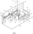
- Figure 1-3 show the above tether management system 2 for reeling in and out a tether 4 connected to an unmanned aerial vehicle (UAV) 6 ( Figure 2 ).
- the tether management system 2 includes a spool 8 having a cylindrical drum 10 flanked on both ends by respective flange members 12, 14 fixedly attached to the drum 10.
- the flange members 12, 14 retain the tether 4 on the spool 8.
- the flange members 12, 14 may be of a diameter that allows the spool 8 to hold a length of, for example, 70m of tether 4.
- Each flange member 12, 14 has a rim 16 and spokes 18 radially extending from a central portion thereof to the rim 16.
- the rim 16 and the spokes 18 define openings 20 in the flange members 12, 14.
- the tether 4 carries power lines supplying power to the UAV 6, amongst others.
- the tether 4 may thus generate a considerable amount of heat, especially after prolonged use, and the openings 20 in the flange members 12, 14 facilitate dissipation of this heat that is generated.
- One or more fans may be further employed to blow air directly at the wound tether 4 to further aid in cooling it.
- Such a design of the spool 8 is simple and yet reliable.
- the thickness of the cylindrical drum 10 may be in the range of 1 to 10 times, preferably 5 times, the thickness of the tether 4 to be wound around the drum 10.
- This thickness of the drum 10 allows the tether 4 to be neatly spooled without the need for a level winding mechanism. It is found that this thickness of the drum 10 is optimized considering factors like the cooling ability, the diameter of the spool 8 required for holding a given length of tether 4 and the necessity to prevent tether entanglement.
- a through beam type photoelectric sensor (not shown) is used to detect that only about 5m of the 70m of tether is left on the spool 8, i.e. the end of the spool 8 is near.
- This photoelectric sensor has a light emitting element that is disposed on one side of the spool 8 and a light receiving element that is disposed on the other side of the spool 8. When the length of the tether 4 wound on the spool is more than 5m, light emitted by the light emitting element is blocked by the tether 4 and cannot reach the light receiving element.
- sensors can also be used for detecting the end of the spool 8. These sensors include, but are not limited to, retroreflective photoelectric sensors, diffused photoelectric sensors and limit switches.
- the spool 8 is connected to a shaft of a motor which is operated to turn the spool 8 in both clockwise and anti-clockwise directions.
- the motor is mounted in a cylindrical housing 22 with a proximal end thereof adjacent the spool 8.
- Connected to a distal end of the cylindrical housing 22 is a first cantilevered beam 24 and a second cantilevered beam 25 extending in opposite directions to each other to a first sidewall 26 and a second sidewall (not shown) of a housing 28.
- the spool 8 is suspended horizontally with respect to a base 30 of the housing 28.
- the spool 8 is disposed such that a radial plane thereof is, more or less, parallel to the base 30 of the housing 28.
- a guard 32 may be provided to cover a circumferential section of the spool 8 for preventing tether slippage.
- the guard 32 may cover about 75% of the circumferential section of the spool 8 leaving a small section uncovered for the tether 4 to be reeled in and out of the spool 8.
- the guard 32 may be supported in place by the cylindrical housing 22 or mounted on the base 30 or a sidewall of the housing 28.
- the tether management system 2 further includes a tension assembly 40 mounted to an inner wall (not shown) of the housing 28.
- This tension assembly 40 shown in Figure 3 , includes a bracket 42 that is mounted to the inner wall.
- the bracket 42 supports a first guide pulley 44, a tension pulley 46 and a fairlead 48.
- the fairlead 48 includes two pairs of rollers 50 transverse to each other. One of these rollers 50 urges the tether 4 against the tension pulley 46.
- Connected to the tension pulley 46 is a tension sensor 52 for measuring the tension of the tether 4. Force exerted by the tether 4 on the tension pulley 46 will be detected and measured by the tension sensor 52.
- a roof (not shown) of the housing 28 includes an opening through which the fairlead 48 is exposed.
- the tether management system 2 also includes a compensator system 60 that engages the tether 4 between the spool 8 and the tension assembly 40.
- the compensator system 60 includes a moveable pulley 62 through which tether 4 that is reeled out of the spool 8 is threaded.
- the moveable pulley 62 can be biased and moveable along a linear path, in a direction indicated by doubleheaded arrow X, to adjust the tension of the tether 4 during use.
- the moveable pulley 62 is supported on a pulley block 64.
- This pulley block 64 includes two bushings 66 having ball bearings (not shown) therein.
- Two elongated guide rods 68, 70 are inserted through the two bushings 66 of the pulley block 64 to allow the pulley block 64 to slide along them.
- Two end blocks 72, 74 are connected to the ends of the two guide rods 68, 70.
- One end block 72 is disposed on the sidewall 26 of the housing 28 proximal to the spool 8.
- the other end block 74 is disposed on a pillar 75 of the housing 28, distal from the spool 8.
- Both guide rods 68, 70 are disposed at about the same height from the base 30 of the housing 28 to define the linear path on which the pulley block 64, and thus the moveable pulley 62, can slide along.
- an elongated helical compression spring 80 that has a free length close to or the same as the length of the inner rod 68.
- the pulley block 64, and along with it the moveable pulley 62 is pushed towards the second end block 74 that is distal from the spool 8. This position of the moveable pulley 62 is shown as Position 1 in Figure 1 .
- the compression spring 80 may be of a unitary design or it may include two or more sections joined via any connectors or adapters, or simply sleeved over the rod abutting one another.
- the compensator system 60 further includes a limit stop 82 sleeved over the outer rod 70 and mounted to the sidewall 26.
- the limit stop 82 is disposed adjacent an intermediate position between the first end block 72 and the second end block 74 to limit movement of the pulley support 64 to be along the first rod 68 and the second rod 70 between the second end block 74 and the limit stop 82.
- the helical compression spring 80 has a working length of about 25%-75% of its free length. For a selected range of tension of operation of the tether 4, the length of the spring is selected such that the spring force is 0g at uncompressed state and about 400g (maximum operating load) when it is compressed to be at the limit stop 82. Thus, the working length is about 40% of the maximum length of the compression spring 80.
- the tether management system 2 further includes a second guide pulley 84 mounted to the sidewall 26 to be on a same horizontal plane as the moveable pulley 62.
- the tether management system 2 further includes a fixed pulley 86 mounted on a columnal structure 88 to be on the same horizontal plane as the second guide pulley 84 and the moveable pulley 62.
- the columnal structure 88 extends from the base 30 of the housing 28. The inner wall (not shown) described above is supported by this columnal structure 88.
- the tether 4 is threaded out of the spool 8, through the second guide pulley 84, the moveable pulley 62 and the fixed pulley 86 along a path on a horizontal plane.
- the tether 4 is further threaded through the first guide pulley 44 and the tension pulley 46 of the tension assembly 40 to have its path translated in a vertical plane.
- the tether 4 is further threaded through the fairlead 48 to extend out of the housing 28 for connection to the UAV 6.
- an exit section of the path of the tether 4 is transverse to the linear path of the moveable pulley 62.
- the tether management system further includes a controller 100 that is connected to a touchscreen input and/or a mobile phone (both not shown) via a Bluetooth connection. Through a suitable interface on any of these devices, the controller 100 is able to receive, from a user, a desired tension for operating the tether 4 and to control the rotation of the spool 8 to reel in and reel out the tether 4 based on a difference between a measured tension provided by the tension sensor 52 and the desired tension. The controller 100 is further able to receive an end of spool signal from the photoelectric sensor.
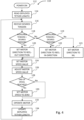
- Figure 4 is a flowchart showing the method 110.
- the method 110 starts in a POWER ON step 112 when power to the controller 100 is turned on.
- the method 110 next proceeds to a READ DEPLOYED TETHER LENGTH step 114, wherein the controller 100 reads data associated with a length of the tethered 4 deployed from a non-volatile memory (not shown), for example, an SD card.
- the method 110 next proceeds to a RECEIVE DESIRED TENSION step 116, wherein the controller 100 is able to receive from a user via either the touchscreen or mobile phone a desired tension value at which deployed tether 4 is to be maintained.
- the method 110 next proceeds to a MEASURED TENSION > DESIRED TENSION? decision step 118, wherein the controller 100 determines if the measured tension captured by the tension sensor 52 is greater than the desired tension set by the user.
- the method 110 proceeds to a SET MOTOR DIRECTION TO REEL-OUT DIRECTION step 120, wherein a direction to operate the motor is set to a reel-out direction. If however it is determined in the decision step 118, that the measured tension is not greater but lower than or equal to the desired tension, the method 110 proceeds to a MEASURED TENSION ⁇ DESIRED TENSION? decision step 119, wherein the controller 100 determines if the measured tension is lower than the desired tension.
- the method 110 proceeds to a SET MOTOR DIRECTION TO REEL-IN DIRECTION step 122, wherein the direction to operate the motor is set to a reel-in direction that is opposite to the reel-out direction. If however it is determined in the decision step 119, that the measured tension is not lower than the desired tension but equal to the desired tension, the method 110 proceeds to SET MOTOR DIRECTION TO NIL step 123, wherein the direction to operate the motor is set to zero to indicate that the motor need not be rotated.
- the method 110 proceeds to a SET MOTOR SPEED VALUE step 124, wherein the controller 110 determines a speed value for driving the motor using a PID control based on the difference between the measured tension and the desired tension.
- the determined speed value may range, for example, from 0 - 255.
- the method 110 further proceeds to an ADJUST MOTOR SPEED VALUE step 126, wherein the controller 100 adjusts the speed value obtained in the SET MOTOR SPEED VALUE step 124 based on the length of tether 4 deployed.
- the spool 8 may be able to hold 70m of tether.
- the motor speed value is adjusted downwards to be capped at cap values decreasing with increasing length.
- the cap value may be correspondingly lowered to 127 for a length of deployed tether 4 of 62.5m, and correspondingly lowered to 0 for a length of deployed tether 4 of 65m.
- the motor speed value may be determined to be 199 in the SET MOTOR SPEED VALUE step 124. But when it is determined that the length of the deployed tether is at 62.5m in the ADJUST MOTOR SPEED VALUE step 126, the motor speed value is lowered from 199 to be capped at the cap value of 127 corresponding to the 62.5m mark. As a further example, the motor speed value may be determined to be 76 in the SET MOTOR SPEED VALUE step 124.
- the motor speed value is lowered from 76 to be capped at the cap value of 0 corresponding to the 65m mark.
- the remaining 5m of the tether 4 is used as a buffer.
- the method 110 next proceeds to an END OF SPOOL REACHED? decision step 128, wherein the controller 100 determines if an end of spool condition, e.g. 65m of the tether 4 has been deployed leaving only about 5m of tether 4 left on the spool 8, is reached by reading the photoelectric sensor. If it is determined in this decision step 128 that the end of spool is reached, the method 110 proceeds to a SET MOTOR SPEED VALUE TO ZERO step 130, wherein the controller 100 sets the motor speed value to zero regardless of its value as determined in the steps 124, 126. If it is determined in this step 130 that the end of spool has not been reached, no change is made to the motor speed value determined earlier.
- an end of spool condition e.g. 65m of the tether 4 has been deployed leaving only about 5m of tether 4 left on the spool 8
- the method 110 proceeds to a SET MOTOR SPEED VALUE TO ZERO step 130, wherein the
- the method 110 proceeds to an OPERATE MOTOR step 132, wherein the controller 100 operates the motor according with the set direction and motor speed to reel the tether 4 in or out to return the tension of the tether 4 closer to the desired tension set by the user.
- the method 110 further proceeds to an UPDATE DEPLOYED TETHER LENGTH step 134, wherein the controller 100 reads the number of revolutions made by the motor via a motor encoder (not shown), calculates the amount of tether 4 reeled in or out and updates the length of tether 4 deployed in the non-volatile memory.
- Each turn of the motor will correspond to a different tether length depending on how much tether is left on the spool 8.
- a formula corresponding to a 3rd order best fit curve between two known deployed lengths of 0m and 60m is used. Although such a formula is not very accurate, the length of tether obtained using the formula is acceptable as the user does not need to know the exact length of the tether.
- the length of tether deployed is also displayed on an LCD screen (not shown) or the user's mobile phone so that the user is aware of the amount of tether 4 available in the spool 8 to enable the user to operate the UAV 6 accordingly.
- the user can choose to fly the UAV 6 higher, further or both. Without this information, the user will not be aware that tether 4 may be running out and their filming or photo taking using the UAV 6 might be affected by the sudden jam when the tether 4 runs out.
- the method 110 loops around the steps 116 -134 to provide a closed-loop control of the spool 8.
- the controller 100 is able to reel in and reel out tether 4 such that the tension of the tether 4 is close to or at the desired tension.
- Any change in the tension in the tether 4, if not immediately corrected, may result in jerky movements of the UAV 6.
- the compensator system 60 can mitigate this problem at least to some extent.
- the controller 100 will keep the motor still.
- the compression spring 80 is compressed such that the force of the spring 80 is double the tension experienced by the tether 4.
- the position of the moveable pulley 62 is at Position 2 in Figure 1 .
- the moveable pulley 62 When the tension of the tether 4 is greater than the desired tension level and before the controller 100 is able to reel out the tether 4 as described above, the moveable pulley 62 is forced to slide along the rods 68, 70 in a direction of the first end block 72 to move to Position 3 as shown in Figure 1 . In this position of the moveable pulley 62, the compression spring 80 is compressed, such that the force in the spring 80 is about twice the new increased tension in the tether 4. This movement of the moveable pulley 62 closer to the spool 8 reduces the length of the tether 4 between the spool 8 and the tension pulley 46.
- the tension sensor 52 When there is a sudden decrease in tension in the tether 4 due either to the UAV 6 decreasing in height or a decrease in the wind speed, the tension sensor 52 will sense the decrease in tension in the tether 4. As described above, the controller 100 will operate the motor to reel in the tether 4. However, due to latency in the method 110, there will be a delay in reeling in the tether 4. Before the motor is able to reel in the tether 4, the moveable pulley 62 in the compensator system 60 will move in a direction towards Position 1 as shown in Figure 1 to decompress the compression spring 80, such that the force in the compression spring 80 is about twice the new decreased tension in the tether 4.
- This movement of the moveable pulley 62 draws more tether 4 in to increase the length of the tether 4 between the spool 8 and the tension pulley 46.
- the length of the tether 4 between the tension pulley 46 and the UAV 6 is reduced, thus reducing slack and increasing the tension in the tether 4.
- the controller 100 finally operates the motor to reel in the tether 4, the tension in the tether will increase, and the moveable pulley 62 will once again be pushed by the tether 4 to move back to its steady state Position 2.
- the tether management system 2 having a moveable pulley 62 moveable along a linear path as described above may be compactly built.
- the compensator system 60 of the tether management system 2 can maintain tension in the tether 4 within an acceptable range, compensating for the latency in the tension sensor 52 and motor feedback loop.
- the compensator system 60 can instantaneously reel out tether 4 when more tether 4 is required thus preventing the tether 4 from experiencing a sudden large tension force.
- the compensator system 60 can also instantaneously reel in the tether 4 when there is too much tether slack below the UAV 6, thereby lowering the risk of tether entanglement with objects near the UAV and preventing the tether 4 from experiencing a sudden loss of tension.
- the compensator system 2 scales down the change in tension of the tether 4 but it does not eliminate it. This is important to allow the tension sensor 52 to continue to sense a change in tension so that the controller 100 can change the motor's direction and speed as described above. This allows the tether management system 2 to perform its function of keeping the tether 4 within an acceptable tension range responsively.
- tether management system 2 is described for use with a UAV 6, those skilled in the art will recognize that such a system 2 can be used in other applications including, but not limited to, tethering of other robots, e.g. an underwater robot, and also in applications for managing a cable between two moving vehicles.
- the compensator system 2 may include two compression springs instead of only one 80 as described above.
- a second compression spring (not shown) may be sleeved over the second rod 70 for example.
- the limit stop 82 will accordingly have to be moved to another location.
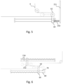
- a torsion spring 150 such as that shown in Figure 5 may be used instead. One end of the torsion spring 150 is attached to a side wall 151 and the other end is attached to the pulley block 64.
- the compensator system 60 may include a second moveable pulley 152 that is moveable along a second pair of moveable rods 154 disposed side by side with the moveable pulley 62 and its corresponding rods 68, 70 as shown in Figure 6 .
- a second moveable pulley 152 that is moveable along a second pair of moveable rods 154 disposed side by side with the moveable pulley 62 and its corresponding rods 68, 70 as shown in Figure 6 .
- Such a design having two or more moveable pulleys in series can provide a larger buffer, and the reel in and reel out speed may also be doubled.
- the double rod 68, 70 in the above described embodiment may be replaced with a linear track on which the pulley block 64 is slidable.
- a single rod may be used.
- the pulley block 64 may be provided with rollers that rest against the sidewall to prevent the pulley block 64 from rotating about the single rod.
- the compression spring 80 sleeved on the rod design described above may be replaced with a compression spring in a tubular structure.
- This tubular structure has a groove running along its length that allows the pulley block 64 to be coupled to an end of the compression spring and to be slidable thereon.
- the fixed pulleys 84, 86 may be omitted.
- the spool 8, moveable pulley 62 and the tension assembly 40 may be appropriately spaced apart from one another to avoid interference with one another or with the walls of the housing 28.
Landscapes
- Engineering & Computer Science (AREA)
- Aviation & Aerospace Engineering (AREA)
- Mechanical Engineering (AREA)
- Remote Sensing (AREA)
- Chemical & Material Sciences (AREA)
- Combustion & Propulsion (AREA)
- Tension Adjustment In Filamentary Materials (AREA)
- Electrotherapy Devices (AREA)
- Air Bags (AREA)
- Controlling Rewinding, Feeding, Winding, Or Abnormalities Of Webs (AREA)
Claims (15)
- Haltegurtverwaltungssystem (2), umfassend:eine Spule (8), die drehbar ist, um einen Haltegurt (4) ein- und auszurollen;eine Spannrolle (46), die mit dem Haltegurt (4) in Eingriff steht;einen Spannungssensor (52), der mit der Spannrolle (46) gekoppelt ist, um eine Spannung des Haltegurts (4) zu messen;eine Steuerung (100) zum Empfangen einer gewünschten Spannung des Haltegurts und zum Steuern der Drehung der Spule (8), um den Haltegurt basierend auf einer Differenz zwischen einer gemessenen Spannung von dem Spannungssensor (52) und der gewünschten Spannung des Haltegurts (4) ein- und auszurollen; dadurch gekennzeichnet, dass das Haltegurtverwaltungssystem (2) ferner umfasst:
eine bewegliche Rolle (62), die nicht mit dem Spannungssensor (52) gekoppelt ist und angeordnet ist, um den Haltegurt zwischen der Spule (8) und der Spannrolle (46) in Eingriff zu bringen, wobei die bewegliche Rolle (46) in eine stationäre Position entlang eines linearen Pfads vorgespannt ist, wenn der Haltegurt die gewünschte Spannung aufweist, und entlang des linearen Pfads in beide Richtungen von der stationären Position bewegbar ist, um eine Spannung des Haltegurts (4) einzustellen, wenn die Spannung des Haltegurts von der gewünschten Spannung abweicht. - Haltegurtverwaltungssystem (2) nach Anspruch 1, ferner umfassend eine längliche Druckfeder (80) zum Vorspannen der beweglichen Rolle (62) entlang des linearen Pfads.
- Haltegurtverwaltungssystem (2) nach Anspruch 2, ferner umfassend eine erste Stange (68), über die die längliche Druckfeder (80) geschoben ist.
- Haltegurtverwaltungssystem (2) nach Anspruch 3, ferner umfassend:eine zweite Stange (70), die zumindest im Wesentlichen parallel zu der ersten Stange (68) ist; undeinen Rollenträger (64) zum Tragen der beweglichen Rolle (62), wobei der Rollenträger (64) zwei Buchsen (66) beinhaltet, durch die die erste Stange (68) und die zweite Stange (70) dringen, um zu ermöglichen, dass der Rollenträger (64) darauf verschiebbar ist.
- Haltegurtverwaltungssystem (2) nach Anspruch 4, ferner umfassend:einen ersten Endblock (74) an einem ersten Ende der ersten Stange (68) und der zweiten Stange (70); undeinen zweiten Endblock (72) an einem zweiten Ende der ersten Stange (68) und der zweiten Stange (70); wobei die längliche Druckfeder (80) eine freie Länge aufweist, die im Wesentlichen gleich einer Länge der ersten Stange (68) ist.
- Haltegurtverwaltungssystem (2) nach Anspruch 1, wobei die Dicke der Spule (8) im Bereich des 1-10-fachen der Dicke des Haltegurts liegt.
- Haltegurtverwaltungssystem (2) nach Anspruch 1, ferner umfassend ein Gehäuse (28) mit einer Basis (30), einem der Basis gegenüberliegenden Dach und einer Seitenwand (26) zwischen der Basis (30) und dem Dach, und wobei die Spule (8) so angeordnet ist, dass eine radiale Ebene davon zumindest im Wesentlichen parallel zu der Basis (30) des Gehäuses ist.
- Haltegurtverwaltungssystem (2) nach Anspruch 7, ferner umfassend:eine feste Rolle (86), die angeordnet ist, um den Haltegurt zwischen der beweglichen Rolle (62) und der Spannrolle (46) in Eingriff zu bringen;wobei die Spannrolle (6) den Haltegurt (4) entlang eines Ausgangsabschnitts eines Pfads des Haltegurts führt, der sich durch das Dach des Gehäuses (28) erstreckt.
- Haltegurtverwaltungssystem (2) nach Anspruch 8, wobei der Ausgangsabschnitt quer zu dem linearen Pfad der beweglichen Rolle (62) verläuft.
- Haltegurtverwaltungssystem (2) nach Anspruch 1, wobei die Steuerung (100) angepasst ist, um eine Geschwindigkeit zum Drehen der Spule (8) basierend auf einer Differenz zwischen der gemessenen Spannung des Haltegurts (4) und der gewünschten Spannung zu bestimmen.
- Haltegurtverwaltungssystem (2) nach Anspruch 10, wobei die Steuerung (100) angepasst ist, um die Geschwindigkeit zum Drehen der Spule (8) ferner auf einen Cap-Wert zu begrenzen, der einer Länge des Haltegurts (4) entspricht, die auf der Spule verbleibt, wenn weniger als eine vorbestimmte Länge des Haltegurts auf der Spule (8) verbleibt.
- Verfahren (110) zum Verwalten eines Haltegurts (4) auf einer Spule (8), wobei das Verfahren umfasst:Empfangen (116) einer gewünschten Spannung für einen entfalteten Haltegurt (4);Ineingriffbringen des Haltegurts (4) mit einer Spannrolle (46);Messen einer Spannung des entfalteten Haltegurts (4) unter Verwendung eines Spannungssensors (52), der mit der Spannrolle (46) gekoppelt ist; undDrehen der Spule (8), um den Haltegurt (4) basierend auf einer Differenz zwischen der gemessenen Spannung und der gewünschten Spannung ein- und auszurollen; dadurch gekennzeichnet, dass das Verfahren ferner umfasst:Ineingriffbringen des Haltegurts (4) mit einer beweglichen Rolle (62), die von dem Spannungssensor (52) beabstandet ist und zwischen der Spule (8) und der Spannrolle (46) angeordnet ist; undVorspannen der beweglichen Rolle (62) in eine stationäre Position entlang eines linearen Pfads, wenn der Haltegurt (4) die gewünschte Spannung aufweist, und entlang des linearen Pfads in beide Richtungen von der stationären Position bewegbar ist, um eine Spannung des Haltegurts (4) einzustellen, wenn die Spannung des Haltegurts von der gewünschten Spannung abweicht.
- Verfahren (110) nach Anspruch 12, wobei das Verfahren ferner das Bestimmen einer Geschwindigkeit zum Drehen der Spule (8) basierend auf einer Differenz zwischen der gemessenen Spannung und der gewünschten Spannung umfasst, und wobei das Drehen der Spule (8) das Drehen der Spule (8) mit der bestimmten Geschwindigkeit beinhaltet.
- Verfahren (110) nach Anspruch 13, ferner umfassend das Begrenzen der Geschwindigkeit zum Drehen der Spule (8) auf einen Cap-Wert, der einer Länge des Haltegurts entspricht, die auf der Spule verbleibt, wenn weniger als eine vorbestimmte Länge des Haltegurts auf der Spule verbleibt.
- Verfahren (110) nach Anspruch 12, wobei das Vorspannen der beweglichen Rolle (62) das Vorspannen der beweglichen Rolle (62) mit einer länglichen Druckfeder (80) umfasst, die eine Kraft aufweist, die etwa das Doppelte der Spannung des Haltegurts (4) über einen Bereich der gewünschten Betriebsspannung des Haltegurts beträgt.
Applications Claiming Priority (1)
| Application Number | Priority Date | Filing Date | Title |
|---|---|---|---|
| PCT/SG2019/050623 WO2021126071A1 (en) | 2019-12-18 | 2019-12-18 | A tether management system and method |
Publications (4)
| Publication Number | Publication Date |
|---|---|
| EP4077199A1 EP4077199A1 (de) | 2022-10-26 |
| EP4077199A4 EP4077199A4 (de) | 2023-09-06 |
| EP4077199C0 EP4077199C0 (de) | 2025-05-28 |
| EP4077199B1 true EP4077199B1 (de) | 2025-05-28 |
Family
ID=76477960
Family Applications (1)
| Application Number | Title | Priority Date | Filing Date |
|---|---|---|---|
| EP19956182.0A Active EP4077199B1 (de) | 2019-12-18 | 2019-12-18 | Haltebandverwaltungssystem und -verfahren |
Country Status (9)
| Country | Link |
|---|---|
| US (1) | US12358764B2 (de) |
| EP (1) | EP4077199B1 (de) |
| JP (1) | JP7465581B2 (de) |
| KR (1) | KR20220117881A (de) |
| CN (1) | CN115243995A (de) |
| AU (1) | AU2019479573A1 (de) |
| CA (1) | CA3164954A1 (de) |
| IL (1) | IL293741A (de) |
| WO (1) | WO2021126071A1 (de) |
Families Citing this family (9)
| Publication number | Priority date | Publication date | Assignee | Title |
|---|---|---|---|---|
| US10696420B2 (en) * | 2016-08-17 | 2020-06-30 | Hood Technology Corporation | Rotorcraft-assisted system and method for launching and retrieving a fixed-wing aircraft into and from free flight |
| EP3994060B1 (de) * | 2020-04-06 | 2024-08-07 | Workhorse Group Inc. | Flugzeugsysteme und -verfahren |
| US11834199B2 (en) * | 2021-04-08 | 2023-12-05 | Easy Aerial Inc. | Hybrid unmanned aerial vehicle systems with automated tether assembly |
| US12454445B2 (en) | 2021-07-30 | 2025-10-28 | Infravision Holdings Pty Ltd. | Cable winch |
| US12263925B1 (en) | 2022-05-20 | 2025-04-01 | Stanley C. C. Link | Automatic floating dock adjuster |
| US12466585B2 (en) * | 2022-06-22 | 2025-11-11 | Airhive Inc. | Unmanned aerial vehicle (UAV) for facilitating aerial deliveries of cargo |
| CN116891159A (zh) * | 2023-06-13 | 2023-10-17 | 中国船舶集团有限公司第七〇八研究所 | 一种缆绳预张力自适应调节装置 |
| US20250330007A1 (en) * | 2024-04-22 | 2025-10-23 | Microsoft Technology Licensing, Llc | Device cable length adjustment |
| CN118529554B (zh) * | 2024-07-25 | 2024-09-17 | 广东冠业新材料有限公司 | 一种聚酯单丝生产导丝张力控制装置及其控制方法 |
Family Cites Families (29)
| Publication number | Priority date | Publication date | Assignee | Title |
|---|---|---|---|---|
| US2042481A (en) * | 1935-05-27 | 1936-06-02 | Joseph C Patterson | Device for paying out a hoisting line |
| JPS5061567U (de) * | 1973-10-06 | 1975-06-05 | ||
| US4058277A (en) * | 1974-09-19 | 1977-11-15 | Dornier Gmbh. | Captive remote-controlled helicopter |
| JPS54133453A (en) | 1978-04-10 | 1979-10-17 | Hitachi Ltd | Detecting apparatus of coil remaining turn |
| JPS6031266U (ja) * | 1983-04-19 | 1985-03-02 | 吉武 一男 | 温室等のカーテン開閉ワイヤの弛緩防止装置 |
| JPS60100394U (ja) * | 1983-12-15 | 1985-07-09 | 株式会社神戸製鋼所 | ウインチドラムのロ−プ過巻取り、過繰出し防止装置 |
| JPS6186392A (ja) * | 1984-08-31 | 1986-05-01 | カヤバ工業株式会社 | ラムテンシヨナ−装置 |
| US4895079A (en) * | 1986-03-19 | 1990-01-23 | Beatty Robert A | Vehicle hauling process and apparatus |
| US4981456A (en) * | 1988-06-20 | 1991-01-01 | Yamaha Hatsudoki Kabushiki Kaisha | Remote controlled helicopter |
| FR2701919B1 (fr) * | 1993-02-23 | 1995-05-24 | Cr2A | Magasin pour conducteur de liaison entre un engin volant téléguidé récupérable et un poste de commande au sol. |
| FR2712563A1 (fr) * | 1993-11-18 | 1995-05-24 | Cr2A | Equipement d'un engin volant piloté par fil à partir d'un poste de commande, pour transmission bidirectionnelle de signaux par le fil. |
| JPH07206385A (ja) | 1994-01-25 | 1995-08-08 | Komatsu Mec Corp | ロープ巻取り、繰出し検出装置 |
| JP2000044179A (ja) * | 1998-07-29 | 2000-02-15 | Sumitomo Constr Mach Co Ltd | ロープ・テンショナー |
| JP2002003178A (ja) * | 2000-06-26 | 2002-01-09 | Hitachi Zosen Corp | 洋上補給用ウインチ |
| US7222839B2 (en) * | 2004-02-12 | 2007-05-29 | Gorbel, Inc. | Cable slack and guide monitoring apparatus and method for a lift device |
| FR2888157B1 (fr) | 2005-07-08 | 2009-10-09 | Michelin Soc Tech | Methode de regulation de tension d'un renfort de pneumatique |
| GB0705110D0 (en) * | 2007-03-16 | 2007-04-25 | Lewis Ltd | Wireline intervention system |
| CN102135651B (zh) | 2011-04-08 | 2012-07-04 | 中国船舶重工集团公司第七一五研究所 | 一种光纤微缆收放绞车 |
| US9290269B2 (en) * | 2013-03-15 | 2016-03-22 | CyPhy Works, Inc. | Spooler for unmanned aerial vehicle system |
| CN105173105A (zh) * | 2015-08-04 | 2015-12-23 | 徐州创航科技有限公司 | 一种用于系留无人机飞行器的自动收放线装置 |
| US10399704B2 (en) * | 2016-03-10 | 2019-09-03 | Blue Vigil, LLC | Reactive tether spool |
| CN105776049B (zh) | 2016-04-26 | 2019-08-23 | 马鞍山市新桥工业设计有限公司 | 一种用于石油勘探的智能卷扬机 |
| CN107757942A (zh) * | 2016-08-19 | 2018-03-06 | 深圳航天旭飞科技有限公司 | 无人机的供电控制系统 |
| CN206266012U (zh) | 2016-08-30 | 2017-06-20 | 嘉兴市天信电线有限公司 | 电缆自动收放器 |
| CN109963718B (zh) | 2016-11-14 | 2021-01-05 | 旭化成株式会社 | 卷对卷印刷装置 |
| SG11201908005PA (en) | 2017-03-06 | 2019-09-27 | Hoverfly Technologies Inc | Constant tension tether management system for tethered aircraft |
| JP6883844B2 (ja) | 2017-03-07 | 2021-06-09 | 株式会社プロジェクト アドベンチャー ジャパン | 延線装置 |
| CN208883219U (zh) * | 2018-09-06 | 2019-05-21 | 深圳市安泽智能工程有限公司 | 光纤收放装置 |
| CN109626143B (zh) * | 2019-02-19 | 2024-02-27 | 深圳市赛为智能股份有限公司 | 一种系留无人机智能收放线装置及其工作方法 |
-
2019
- 2019-12-18 US US17/787,523 patent/US12358764B2/en active Active
- 2019-12-18 KR KR1020227021557A patent/KR20220117881A/ko not_active Ceased
- 2019-12-18 IL IL293741A patent/IL293741A/en unknown
- 2019-12-18 CA CA3164954A patent/CA3164954A1/en active Pending
- 2019-12-18 JP JP2022537495A patent/JP7465581B2/ja active Active
- 2019-12-18 CN CN201980103522.5A patent/CN115243995A/zh active Pending
- 2019-12-18 WO PCT/SG2019/050623 patent/WO2021126071A1/en not_active Ceased
- 2019-12-18 AU AU2019479573A patent/AU2019479573A1/en active Pending
- 2019-12-18 EP EP19956182.0A patent/EP4077199B1/de active Active
Also Published As
| Publication number | Publication date |
|---|---|
| CN115243995A (zh) | 2022-10-25 |
| AU2019479573A8 (en) | 2022-08-18 |
| JP2023512146A (ja) | 2023-03-24 |
| KR20220117881A (ko) | 2022-08-24 |
| CA3164954A1 (en) | 2021-06-24 |
| IL293741A (en) | 2022-08-01 |
| AU2019479573A1 (en) | 2022-06-23 |
| JP7465581B2 (ja) | 2024-04-11 |
| US12358764B2 (en) | 2025-07-15 |
| WO2021126071A1 (en) | 2021-06-24 |
| EP4077199A1 (de) | 2022-10-26 |
| US20220380186A1 (en) | 2022-12-01 |
| EP4077199C0 (de) | 2025-05-28 |
| EP4077199A4 (de) | 2023-09-06 |
Similar Documents
| Publication | Publication Date | Title |
|---|---|---|
| EP4077199B1 (de) | Haltebandverwaltungssystem und -verfahren | |
| US20180251216A1 (en) | Constant tension tether management system for atethered aircraft | |
| EP3636581A1 (de) | Kabelversatznachweis mit kontakt | |
| CN115557320B (zh) | 一种制导光纤线团的全自动缠绕装置及方法 | |
| EP1112979B1 (de) | Verfahren und Vorrichtung zur Regelung der Zugspannung einer optischen Faser | |
| US20010033727A1 (en) | Optical fibre tensioning device and method of controlling the tension applied to an optical fibre | |
| US6588695B1 (en) | Method and device for unwinding elongated stock | |
| CN108415134B (zh) | 调整套管放线张力的方法及主控系统 | |
| CN202754629U (zh) | 自动络纱机的纱线退绕辅助装置及具备该装置的卷绕装置 | |
| KR101701460B1 (ko) | 광통신 포설용 마이크로튜브용 고속 정렬권취기 | |
| KR20180089948A (ko) | 평행 권사 장치 및 방법 | |
| EP2913293A1 (de) | Vorrichtung und Verfahren zum Aufspulen von Versorgungskabeln oder Drahtseilen | |
| US11713118B1 (en) | Constant tension tether management system for a tethered aircraft | |
| CN214879222U (zh) | 一种用于收放光纤电缆的光纤通信设备 | |
| KR101839318B1 (ko) | 윈치의 케이블 캘리브레이션 장치 | |
| RU2819974C1 (ru) | Система автоматической намотки-размотки кабеля привязных БПЛА | |
| JP2019142605A (ja) | 飛行体ウインチ制御装置及び飛行体 | |
| CN109368418B (zh) | 一种自适应收放飞行器线缆的方法 | |
| CN113501390A (zh) | 卷线装置和机器人系统 | |
| CN119508657B (zh) | 一种井道勘测设备 | |
| CN113070357B (zh) | 一种拉丝机调速控制方法 | |
| CN219238876U (zh) | 张力可调的传送装置 | |
| CN118062255A (zh) | 一种无人机吊飞测试方法 | |
| CN119461034A (zh) | 天车控制方法、系统及天车 | |
| JP2005084394A (ja) | テープ状の光ファイバの巻取方法 |
Legal Events
| Date | Code | Title | Description |
|---|---|---|---|
| STAA | Information on the status of an ep patent application or granted ep patent |
Free format text: STATUS: THE INTERNATIONAL PUBLICATION HAS BEEN MADE |
|
| PUAI | Public reference made under article 153(3) epc to a published international application that has entered the european phase |
Free format text: ORIGINAL CODE: 0009012 |
|
| STAA | Information on the status of an ep patent application or granted ep patent |
Free format text: STATUS: REQUEST FOR EXAMINATION WAS MADE |
|
| 17P | Request for examination filed |
Effective date: 20220609 |
|
| AK | Designated contracting states |
Kind code of ref document: A1 Designated state(s): AL AT BE BG CH CY CZ DE DK EE ES FI FR GB GR HR HU IE IS IT LI LT LU LV MC MK MT NL NO PL PT RO RS SE SI SK SM TR |
|
| DAV | Request for validation of the european patent (deleted) | ||
| DAX | Request for extension of the european patent (deleted) | ||
| A4 | Supplementary search report drawn up and despatched |
Effective date: 20230807 |
|
| RIC1 | Information provided on ipc code assigned before grant |
Ipc: B65H 75/44 20060101ALI20230801BHEP Ipc: B65H 59/40 20060101ALI20230801BHEP Ipc: B65H 59/38 20060101ALI20230801BHEP Ipc: B65H 59/36 20060101ALI20230801BHEP Ipc: B64F 3/00 20060101ALI20230801BHEP Ipc: B64C 39/02 20060101ALI20230801BHEP Ipc: B64F 3/02 20060101ALI20230801BHEP Ipc: B65H 75/48 20060101ALI20230801BHEP Ipc: B66D 1/50 20060101AFI20230801BHEP |
|
| REG | Reference to a national code |
Ref country code: DE Ref legal event code: R079 Free format text: PREVIOUS MAIN CLASS: B66D0001500000 Ipc: B64U0010600000 Ref document number: 602019070652 Country of ref document: DE |
|
| GRAP | Despatch of communication of intention to grant a patent |
Free format text: ORIGINAL CODE: EPIDOSNIGR1 |
|
| STAA | Information on the status of an ep patent application or granted ep patent |
Free format text: STATUS: GRANT OF PATENT IS INTENDED |
|
| RIC1 | Information provided on ipc code assigned before grant |
Ipc: B65H 75/48 20060101ALI20241212BHEP Ipc: B64F 3/02 20060101ALI20241212BHEP Ipc: B64C 39/02 20060101ALI20241212BHEP Ipc: B64F 3/00 20060101ALI20241212BHEP Ipc: B65H 59/36 20060101ALI20241212BHEP Ipc: B65H 59/38 20060101ALI20241212BHEP Ipc: B65H 59/40 20060101ALI20241212BHEP Ipc: B65H 75/44 20060101ALI20241212BHEP Ipc: B66D 1/50 20060101ALI20241212BHEP Ipc: B64U 50/34 20230101ALI20241212BHEP Ipc: B64U 10/60 20230101AFI20241212BHEP |
|
| INTG | Intention to grant announced |
Effective date: 20250102 |
|
| GRAS | Grant fee paid |
Free format text: ORIGINAL CODE: EPIDOSNIGR3 |
|
| GRAA | (expected) grant |
Free format text: ORIGINAL CODE: 0009210 |
|
| STAA | Information on the status of an ep patent application or granted ep patent |
Free format text: STATUS: THE PATENT HAS BEEN GRANTED |
|
| AK | Designated contracting states |
Kind code of ref document: B1 Designated state(s): AL AT BE BG CH CY CZ DE DK EE ES FI FR GB GR HR HU IE IS IT LI LT LU LV MC MK MT NL NO PL PT RO RS SE SI SK SM TR |
|
| REG | Reference to a national code |
Ref country code: GB Ref legal event code: FG4D |
|
| REG | Reference to a national code |
Ref country code: CH Ref legal event code: EP |
|
| REG | Reference to a national code |
Ref country code: IE Ref legal event code: FG4D Ref country code: DE Ref legal event code: R096 Ref document number: 602019070652 Country of ref document: DE |
|
| U01 | Request for unitary effect filed |
Effective date: 20250528 |
|
| U07 | Unitary effect registered |
Designated state(s): AT BE BG DE DK EE FI FR IT LT LU LV MT NL PT RO SE SI Effective date: 20250605 |
|
| PG25 | Lapsed in a contracting state [announced via postgrant information from national office to epo] |
Ref country code: ES Free format text: LAPSE BECAUSE OF FAILURE TO SUBMIT A TRANSLATION OF THE DESCRIPTION OR TO PAY THE FEE WITHIN THE PRESCRIBED TIME-LIMIT Effective date: 20250528 |
|
| PG25 | Lapsed in a contracting state [announced via postgrant information from national office to epo] |
Ref country code: NO Free format text: LAPSE BECAUSE OF FAILURE TO SUBMIT A TRANSLATION OF THE DESCRIPTION OR TO PAY THE FEE WITHIN THE PRESCRIBED TIME-LIMIT Effective date: 20250828 Ref country code: GR Free format text: LAPSE BECAUSE OF FAILURE TO SUBMIT A TRANSLATION OF THE DESCRIPTION OR TO PAY THE FEE WITHIN THE PRESCRIBED TIME-LIMIT Effective date: 20250829 |
|
| PG25 | Lapsed in a contracting state [announced via postgrant information from national office to epo] |
Ref country code: PL Free format text: LAPSE BECAUSE OF FAILURE TO SUBMIT A TRANSLATION OF THE DESCRIPTION OR TO PAY THE FEE WITHIN THE PRESCRIBED TIME-LIMIT Effective date: 20250528 |
|
| PG25 | Lapsed in a contracting state [announced via postgrant information from national office to epo] |
Ref country code: HR Free format text: LAPSE BECAUSE OF FAILURE TO SUBMIT A TRANSLATION OF THE DESCRIPTION OR TO PAY THE FEE WITHIN THE PRESCRIBED TIME-LIMIT Effective date: 20250528 |
|
| PG25 | Lapsed in a contracting state [announced via postgrant information from national office to epo] |
Ref country code: RS Free format text: LAPSE BECAUSE OF FAILURE TO SUBMIT A TRANSLATION OF THE DESCRIPTION OR TO PAY THE FEE WITHIN THE PRESCRIBED TIME-LIMIT Effective date: 20250828 |
|
| PG25 | Lapsed in a contracting state [announced via postgrant information from national office to epo] |
Ref country code: IS Free format text: LAPSE BECAUSE OF FAILURE TO SUBMIT A TRANSLATION OF THE DESCRIPTION OR TO PAY THE FEE WITHIN THE PRESCRIBED TIME-LIMIT Effective date: 20250928 |