EP4077060B1 - Véhicule à colonne de direction couplée à un dispositif antivol et masquée par une coque inférieure à protection intégrale - Google Patents
Véhicule à colonne de direction couplée à un dispositif antivol et masquée par une coque inférieure à protection intégrale Download PDFInfo
- Publication number
- EP4077060B1 EP4077060B1 EP20845417.3A EP20845417A EP4077060B1 EP 4077060 B1 EP4077060 B1 EP 4077060B1 EP 20845417 A EP20845417 A EP 20845417A EP 4077060 B1 EP4077060 B1 EP 4077060B1
- Authority
- EP
- European Patent Office
- Prior art keywords
- internal
- impact
- lower shell
- theft device
- lateral
- Prior art date
- Legal status (The legal status is an assumption and is not a legal conclusion. Google has not performed a legal analysis and makes no representation as to the accuracy of the status listed.)
- Active
Links
Images


Classifications
-
- B—PERFORMING OPERATIONS; TRANSPORTING
- B60—VEHICLES IN GENERAL
- B60R—VEHICLES, VEHICLE FITTINGS, OR VEHICLE PARTS, NOT OTHERWISE PROVIDED FOR
- B60R21/00—Arrangements or fittings on vehicles for protecting or preventing injuries to occupants or pedestrians in case of accidents or other traffic risks
- B60R21/02—Occupant safety arrangements or fittings, e.g. crash pads
- B60R21/04—Padded linings for the vehicle interior ; Energy absorbing structures associated with padded or non-padded linings
- B60R21/05—Padded linings for the vehicle interior ; Energy absorbing structures associated with padded or non-padded linings associated with the steering wheel, steering hand lever or steering column
-
- B—PERFORMING OPERATIONS; TRANSPORTING
- B62—LAND VEHICLES FOR TRAVELLING OTHERWISE THAN ON RAILS
- B62D—MOTOR VEHICLES; TRAILERS
- B62D1/00—Steering controls, i.e. means for initiating a change of direction of the vehicle
- B62D1/02—Steering controls, i.e. means for initiating a change of direction of the vehicle vehicle-mounted
- B62D1/16—Steering columns
Definitions
- the invention relates to vehicles comprising a steering wheel secured to a steering column, and more precisely to driver protection provided by complementary lower and upper shells partially masking this steering column.
- Many vehicles particularly land vehicles, include a steering wheel attached to a steering column passing under a dashboard.
- the technical part of the steering column, between the steering wheel and the dashboard, is frequently masked by complementary lower and upper shells, generally made by molding (using a plastic injection process).
- the steering column has rigid and partially projecting elements, generally made of metal
- many lower shells include a lower wall having an internal surface on which a shock absorbing part is installed to define a protective shield for the driver's knees when the latter translates forward during an at least partially frontal impact or sudden braking.
- This shock absorption part usually comprises a polystyrene part and a metal sheet of substantially identical shapes, placed one on top of the other and fixedly joined to one another by overmolding during injection. In order to ensure protection everywhere the lower wall of the lower shell, the shock absorption part extends over almost the entirety of this lower wall while being fixedly attached to the latter, generally by elastic washers.
- the document CN208881891 describes a vehicle comprising a steering column partly hidden by lower and upper shells, the lower shell comprising a lower wall having an internal surface on which a shock absorption part is installed.
- the document CN209079980 describes a vehicle comprising a steering column partly hidden by lower and upper shells, the lower shell comprising a side wall defining a lateral bulge housing part of an anti-theft device.
- Certain vehicles can be marketed according to a first variation, in which a mechanical anti-theft device associated with an ignition key is coupled laterally to the steering column, and a second variation, comprising an electrical type anti-theft device and associated with a so-called Hands-Free Access and Starting (or ADML) function, and therefore without a start key.
- a mechanical anti-theft device associated with an ignition key is coupled laterally to the steering column
- a second variation comprising an electrical type anti-theft device and associated with a so-called Hands-Free Access and Starting (or ADML) function, and therefore without a start key.
- ADML Hands-Free Access and Starting
- the presence of an anti-theft device requires the use of a specific lower shell in which one of the two side walls defines a lateral bulge housing a part of the anti-theft device. If we want to provide lateral protection of the knees under the anti-theft device we are forced to use a shock absorption part different from that used for the second variation because it includes a lateral extension under the anti-theft device. In other words, we are forced to design and manufacture two different shock absorption parts for the first and second variations, which requires designing, manufacturing and using two sheet metal stamping tools, two injection tools of polystyrene part with overmolding of the sheet metal, and two geometric control tools. This solution is therefore particularly expensive and time-consuming.
- the invention therefore aims in particular to improve the situation.
- a vehicle comprising a steering column partly hidden by complementary lower and upper shells and to which is coupled laterally an anti-theft device, the lower shell comprising a lower wall having an internal surface on which is installed a first shock absorption piece and a side wall defining a lateral bulge housing a part of the anti-theft device.
- This vehicle is characterized by the fact that it also includes a second shock absorption part installed in the side bulge under the anti-theft device.
- the invention aims in particular to propose a vehicle comprising a steering column 1 to which is coupled laterally an anti-theft device 2 and partly masked by complementary lower 3 and upper shells, the lower shell offering protection to the driver on the entire part of its lower wall 4 which can be struck by this driver.
- the vehicle is of the automobile type. This is for example a car. But the invention is not limited to this type of vehicle. Indeed, it concerns any vehicle comprising at least one steering column allowing a driver to control its direction. Consequently, the invention relates at least to land vehicles, apart from motorcycles.
- FIG. 1 a part of an example of a steering column 1 intended to equip a vehicle according to the invention and to be coupled to a steering wheel (or the like), and to which is coupled laterally an anti-theft device 2 intended to block the steering column 1 in its locked state (in the absence of an ignition key).
- This anti-theft device 2 is of the mechanical type and associated with a start key (not shown).
- this steering column 1 As illustrated, part of this steering column 1 is masked by a lower shell 3 and by a complementary upper shell (not illustrated and not concerned by the invention).
- the lower shell 3 comprises a lower wall 4 extended on two opposite sides by first 5 and second 6 side (or longitudinal) walls and by a front wall 7 oriented towards the front seats.
- the first side wall 5 (here on the right) of the lower shell 3 defines a lateral bulge 8 housing a part of the anti-theft device 2 (the remainder being housed in the area located above the lower wall 4 and extending up to 'to the steering column 1).
- This lateral bulge 8 is what differentiates the lower shell 3, here used in the presence of an anti-theft device 2 (mechanical type - first variation), from the lower shell used in the presence of an anti-theft device electric type and associated with a Hands-Free Access and Start function (second variation).
- the lower wall 4 of the lower shell 3 extends into the lateral bulge 8.
- this lower wall 4 has an internal surface 9 on which is installed a first part of shock absorption 10.
- This first shock absorption part 10 comprises, for example, a polystyrene part and a (metallic) sheet of substantially identical shapes, placed one on top of the other and fixedly secured to one another by overmolding during plastic injection. It will be understood that this first shock absorption part 10 is identical to that which equips the lower shell of the second variation, and therefore does not extend into the lateral bulge 8 (since the latter (8) does not exist in this second variation). This use of the same first shock absorption part 10 for the lower shells 3 different from the first and second variations is intended to achieve significant savings.
- a second shock absorption part 11 is installed in the latter (8), under the device anti-theft 2.
- this second shock absorption part 11 under the anti-theft device 2 makes it possible to define locally under the latter (2) another protective screen for the driver's knees when the latter translates forward during 'an at least partially front impact or sudden braking, this other protective screen completing the protective screen defined by the first shock absorption part 10.
- this other protective screen completing the protective screen defined by the first shock absorption part 10.
- the second shock absorption part 11 can be made of a plastic material absorbing energy in the event of an impact.
- a plastic material such as polystyrene or polypropylene can be used.
- the second shock absorption part 11 can have a hollow box structure. This increases its resistance and/or rigidity.
- the second shock absorption part 11 can advantageously be held in a final position in the lateral bulge 8 by a lateral part (here right) 12 of a peripheral edge of the first shock absorption part 10. This advantageously allows the second shock absorption part 11 to be automatically wedged without needing to define a means of fixing by screwing or clipping on the internal face 9 of the lower wall 4 which, in addition, could hinder the installation of the second shock absorption piece 11 in the side bulge 8 and also create aggressive zones for the driver's knees.
- the first side wall 5 of the lower shell 3 can comprise on an internal face of the lateral bulge 8 at least one internal protuberance 13 which passes through an associated hole and defined in the second shock absorption part 11.
- the first side wall 5 of the lower shell 3 comprises on the internal face of the lateral bulge 8 two internal protuberances 13 parallel to each other and passing respectively through two holes associated and defined in the second shock absorption part 11. But the latter could have only one internal protuberance 13 or have more than two internal protuberances 13 (for example three).
- Each internal protuberance 13 may have a circular cylindrical shape, for example and as illustrated without limitation.
- the first side wall 5 of the lower shell 3 can comprise on the internal face of its lateral bulge 8 an internal lateral rib 14 which delimits between it (14) and the lower wall 4 an internal housing 15 housing the second absorption part shock absorber 11, and which defines a stop preventing translation of the latter (11) towards the anti-theft device 2.
- the second shock absorption part 11 is immobilized and does not risk moving in the event of an impact, this which would prevent it from carrying out its protective function.
- each internal protuberance 13 can be defined in the internal housing 15 and can extend along an axis which is parallel to an underlying portion of the lower wall 4.
- the first side wall 5 of the lower shell 3 can comprise in its lateral bulge 8 a through hole 15 in which the free end of the anti-theft device 2 is positioned and which allows the introduction of an ignition key into the latter (2) to unlock it and start the vehicle.
Landscapes
- Engineering & Computer Science (AREA)
- Mechanical Engineering (AREA)
- Steering Controls (AREA)
- Vibration Dampers (AREA)
Description
- La présente invention revendique la priorité de la demande
française 1915306 déposée le 20 décembre 2019 - L'invention concerne les véhicules comprenant un volant solidarisé à une colonne de direction, et plus précisément la protection du conducteur assurée par des coques inférieure et supérieure complémentaires masquant partiellement cette colonne de direction.
- De nombreux véhicules, notamment terrestres, comprennent un volant solidarisé à une colonne de direction passant sous une planche de bord. La partie technique de la colonne de direction, comprise entre le volant et la planche de bord, est fréquemment masquée par des coques inférieure et supérieure complémentaires, généralement réalisées par moulage (par un procédé d'injection d'une matière plastique).
- La colonne de direction comportant des éléments rigides et partiellement saillants, généralement en métal, de nombreuses coques inférieures comprennent une paroi inférieure ayant une surface interne sur laquelle est installée une pièce d'absorption de choc afin de définir un écran protecteur pour les genoux du conducteur lorsque ce dernier se translate vers l'avant lors d'un choc au moins partiellement frontal ou d'un freinage brutal.
- Cette pièce d'absorption de choc comprend habituellement une pièce en polystyrène et une tôle métallique de formes sensiblement identiques, placées l'une sur l'autre et solidarisées fixement l'une à l'autre par surmoulage lors de l'injection. Afin d'assurer une protection en tout endroit de la paroi inférieure de la coque inférieure, la pièce d'absorption de choc s'étend sur la quasi-intégralité de cette paroi inférieure tout en étant solidarisée fixement à cette dernière, généralement par des rondelles élastiques.
- Le document
CN208881891 décrit un véhicule comportant une colonne de direction en partie masquée par des coques inférieure et supérieure, la coque inférieure comprenant une paroi inférieure ayant une surface interne sur laquelle est installée une pièce d'absorption de choc. Le documentCN209079980 décrit un véhicule comportant une colonne de direction en partie masquée par des coques inférieure et supérieure, la coque inférieure comprenant une paroi latérale définissant un renflement latéral logeant une partie d'un dispositif antivol. - Certains véhicules peuvent être commercialisés selon une première déclinaison, dans laquelle un dispositif antivol de type mécanique et associé à une clé de démarrage est couplé latéralement à la colonne de direction, et une seconde déclinaison, comprenant un dispositif antivol de type électrique et associé à une fonction dite d'Accès et Démarrage Main Libre (ou ADML), et donc sans clé de démarrage.
- Dans la première déclinaison, la présence d'un dispositif antivol impose d'utiliser une coque inférieure spécifique dans laquelle l'une des deux parois latérales définit un renflement latéral logeant une partie du dispositif antivol. Si l'on veut assurer une protection latérale des genoux sous le dispositif antivol on est contraint d'utiliser une pièce d'absorption de choc différente de celle utilisée pour la seconde déclinaison car comportant une extension latérale sous le dispositif antivol. En d'autres termes, on est contraint de concevoir et fabriquer deux pièces d'absorption de choc différentes pour les première et seconde déclinaisons, ce qui impose de concevoir, fabriquer et utiliser deux outillages d'emboutissage de tôle, deux outillages d'injection de pièce en polystyrène avec surmoulage de la tôle, et deux outillages de contrôle géométrique. Cette solution est donc particulièrement onéreuse et chronophage.
- L'invention a donc notamment pour but d'améliorer la situation.
- Elle propose notamment à cet effet un véhicule comprenant une colonne de direction en partie masquée par des coques inférieure et supérieure complémentaires et à laquelle est couplé latéralement un dispositif antivol, la coque inférieure comprenant une paroi inférieure ayant une surface interne sur laquelle est installée une première pièce d'absorption de choc et une paroi latérale définissant un renflement latéral logeant une partie du dispositif antivol.
- Ce véhicule se caractérise par le fait qu'il comprend aussi une seconde pièce d'absorption de choc installée dans le renflement latéral sous le dispositif antivol.
- Grâce à la combinaison des première et seconde pièces d'absorption de choc, l'intégralité des éléments rigides et partiellement saillants de la colonne de direction est avantageusement écrantée.
- Le véhicule selon l'invention peut comporter d'autres caractéristiques qui peuvent être prises séparément ou en combinaison, et notamment :
- la seconde pièce d'absorption de choc peut être réalisée dans une matière plastique absorbant l'énergie en cas de choc ;
- la seconde pièce d'absorption de choc peut avoir une structure à caissons creux ;
- la seconde pièce d'absorption de choc peut être maintenue dans une position finale dans le renflement latéral par une partie latérale d'un bord périphérique de la première pièce d'absorption de choc ;
- la paroi latérale de la coque inférieure peut comprendre sur une face interne du renflement latéral au moins une protubérance interne traversant un trou associé et défini dans la seconde pièce d'absorption de choc, de manière à maintenir cette dernière dans une position prédéfinie suivant une direction longitudinale du véhicule ;
- la paroi latérale de la coque inférieure peut comprendre sur la face interne du renflement latéral deux protubérances internes parallèles entre elles et traversant respectivement deux trous associés et définis dans la seconde pièce d'absorption de choc ;
- la paroi latérale de la coque inférieure peut comprendre sur une face interne du renflement latéral une nervure latérale interne, délimitant entre elle et la paroi inférieure de la coque inférieure un logement interne logeant la seconde pièce d'absorption de choc, et définissant une butée empêchant une translation de cette dernière vers le dispositif antivol ;
- chaque protubérance interne peut être définie dans le logement interne et peut s'étendre suivant un axe qui est parallèle à une portion sous-jacente de la paroi inférieure ;
- il peut être éventuellement de type automobile.
- D'autres caractéristiques et avantages de l'invention apparaîtront à l'examen de la description détaillée ci-après, et des dessins annexés (obtenus en CAO/DAO (« Conception Assistée par Ordinateur/Dessin Assisté par Ordinateur »), d'où les lignes apparemment discontinues), sur lesquels :
- [
Fig. 1 ] illustre schématiquement, dans une vue en perspective du côté avant, une partie d'un exemple de colonne de direction d'un véhicule selon l'invention, à laquelle est couplé latéralement un dispositif antivol et partiellement masquée par une coque inférieure, - [
Fig. 2 ] illustre schématiquement, dans une vue du dessus, la coque inférieure de lafigure 1 , équipée d'une première pièce d'absorption de choc mais avant qu'elle ne soit équipée d'une seconde pièce d'absorption de choc, - [
Fig. 3 ] illustre schématiquement, dans une vue en perspective sur un côté latéral, la coque inférieure de lafigure 2 , équipée de ses première et seconde pièces d'absorption de choc, et - [
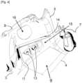
Fig. 4 ] illustre schématiquement, dans une vue en perspective, le renflement latéral de la partie latérale de la coque inférieure de lafigure 2 , équipé de la seconde pièce d'absorption de choc. - L'invention a notamment pour but de proposer un véhicule comprenant une colonne de direction 1 à laquelle est couplé latéralement un dispositif antivol 2 et en partie masquée par des coques inférieure 3 et supérieure complémentaires, la coque inférieure offrant une protection au conducteur sur l'intégralité de la partie de sa paroi inférieure 4 pouvant être heurtée par ce conducteur.
- Dans ce qui suit, on considère, à titre d'exemple non limitatif, que le véhicule est de type automobile. Il s'agit par exemple d'une voiture. Mais l'invention n'est pas limitée à ce type de véhicule. En effet, elle concerne n'importe quel véhicule comprenant au moins une colonne de direction permettant à un conducteur de contrôler sa direction. Par conséquent, l'invention concerne au moins les véhicules terrestres, hormis les motocyclettes.
- On a schématiquement représenté sur la
figure 1 une partie d'un exemple de colonne de direction 1 destinée à équiper un véhicule selon l'invention et à être couplée à un volant (ou analogue), et à laquelle est couplé latéralement un dispositif antivol 2 destiné à bloquer la colonne de direction 1 dans son état verrouillé (en l'absence de clé de contact). - Ce dispositif antivol 2 est de type mécanique et associé à une clé de démarrage (non représentée).
- Comme illustré, une partie de cette colonne de direction 1 est masquée par une coque inférieure 3 et par une coque supérieure complémentaire (non illustrée et non concernée par l'invention).
- La coque inférieure 3 comprend une paroi inférieure 4 prolongée sur deux côtés opposés par des première 5 et seconde 6 parois latérales (ou longitudinales) et par une paroi avant 7 orientée vers les sièges avant.
- Comme illustré partiellement sur les
figures 1 et2 , la première paroi latérale 5 (ici à droite) de la coque inférieure 3 définit un renflement latéral 8 logeant une partie du dispositif antivol 2 (le reste étant logé dans la zone située au-dessus de la paroi inférieure 4 et s'étendant jusqu'à la colonne de direction 1). Ce renflement latéral 8 est ce qui différencie la coque inférieure 3, ici utilisée en présence d'un dispositif antivol 2 (de type mécanique - première déclinaison), de la coque inférieure utilisée en présence d'un dispositif antivol de type électrique et associé à une fonction d'Accès et Démarrage Main Libre (seconde déclinaison). - Contrairement à la seconde déclinaison, dans la première déclinaison la paroi inférieure 4 de la coque inférieure 3 s'étend jusque dans le renflement latéral 8. De plus, cette paroi inférieure 4 a une surface interne 9 sur laquelle est installée une première pièce d'absorption de choc 10.
- Cette première pièce d'absorption de choc 10 comprend, par exemple, une pièce en polystyrène et une tôle (métallique) de formes sensiblement identiques, placées l'une sur l'autre et solidarisées fixement l'une à l'autre par surmoulage lors de l'injection de matière plastique. On comprendra que cette première pièce d'absorption de choc 10 est identique à celle qui équipe la coque inférieure de la seconde déclinaison, et donc ne s'étend pas dans le renflement latéral 8 (puisque ce dernier (8) n'existe pas dans cette seconde déclinaison). Cette utilisation d'une même première pièce d'absorption de choc 10 pour les coques inférieures 3 différentes des première et seconde déclinaisons est destinée à réaliser des économies importantes.
- Comme illustré sur les
figures 3 et4 , afin d'assurer une protection intégrale en tout endroit de la paroi inférieure 4 de la coque inférieure 3 et donc dans le renflement latéral 8, on installe dans ce dernier (8) une seconde pièce d'absorption de choc 11, sous le dispositif antivol 2. - On comprendra que le placement de cette seconde pièce d'absorption de choc 11 sous le dispositif antivol 2 permet de définir localement sous ce dernier (2) un autre écran protecteur pour les genoux du conducteur lorsque ce dernier se translate vers l'avant lors d'un choc au moins partiellement avant ou d'un freinage brutal, cet autre écran protecteur venant compléter l'écran protecteur défini par la première pièce d'absorption de choc 10. Ainsi, l'intégralité des éléments rigides et partiellement saillants de la colonne de direction est avantageusement écrantée, et donc la coque inférieure 3 assure une protection intégrale.
- Par exemple, la seconde pièce d'absorption de choc 11 peut être réalisée dans une matière plastique absorbant l'énergie en cas de choc. Par exemple on peut utiliser une matière plastique absorbante telle que du polystyrène ou du polypropylène.
- On notera, comme illustré non limitativement sur les
figures 3 et4 , que la seconde pièce d'absorption de choc 11 peut avoir une structure à caissons creux. Cela permet d'augmenter sa résistance et/ou sa rigidité. - On notera également, comme illustré non limitativement sur la
figure 3 , que la seconde pièce d'absorption de choc 11 peut être avantageusement maintenue dans une position finale dans le renflement latéral 8 par une partie latérale (ici droite) 12 d'un bord périphérique de la première pièce d'absorption de choc 10. Cela permet avantageusement de caler automatiquement la seconde pièce d'absorption de choc 11 sans avoir besoin de définir un moyen de fixation par vissage ou clippage sur la face interne 9 de la paroi inférieure 4 qui, en plus, pourrait gêner l'installation de la seconde pièce d'absorption de choc 11 dans le renflement latéral 8 et aussi créer des zones agressives pour les genoux du conducteur. - On notera également, comme illustré non limitativement sur les
figures 2 et4 , que la première paroi latérale 5 de la coque inférieure 3 peut comprendre sur une face interne du renflement latéral 8 au moins une protubérance interne 13 qui traverse un trou associé et défini dans la seconde pièce d'absorption de choc 11. Cela permet avantageusement de maintenir la seconde pièce d'absorption de choc 11 dans une position prédéfinie suivant une direction longitudinale du véhicule. Notamment cela permet de la positionner sans risque de la voir tomber avant de placer la première pièce d'absorption de choc 10 dont la partie latérale (ici droite) 12 du bord périphérique vient la bloquer transversalement, comme indiqué précédemment. - Dans l'exemple illustré non limitativement sur les
figures 2 et4 , la première paroi latérale 5 de la coque inférieure 3 comprend sur la face interne du renflement latéral 8 deux protubérances internes 13 parallèles entre elles et traversant respectivement deux trous associés et définis dans la seconde pièce d'absorption de choc 11. Mais cette dernière pourrait ne comporter qu'une seule protubérance interne 13 ou bien comporter plus de deux protubérances internes 13 (par exemple trois). - Chaque protubérance interne 13 peut présenter une forme cylindrique circulaire, par exemple et comme illustré non limitativement.
- On notera également, comme illustré non limitativement sur les
figures 2 et4 , que la première paroi latérale 5 de la coque inférieure 3 peut comprendre sur la face interne de son renflement latéral 8 une nervure latérale interne 14 qui délimite entre elle (14) et la paroi inférieure 4 un logement interne 15 logeant la seconde pièce d'absorption de choc 11, et qui définit une butée empêchant une translation de cette dernière (11) vers le dispositif antivol 2. Ainsi, la seconde pièce d'absorption de choc 11 est immobilisée et ne risque pas de se déplacer en cas de choc, ce qui l'empêcherait d'assurer sa fonction de protection. - On notera également, comme illustré non limitativement sur les
figures 2 et4 , que chaque protubérance interne 13 peut être définie dans le logement interne 15 et peut s'étendre suivant un axe qui est parallèle à une portion sous-jacente de la paroi inférieure 4. - On notera également, comme illustré non limitativement sur les
figures 1 ,3 et4 , que la première paroi latérale 5 de la coque inférieure 3 peut comprendre dans son renflement latéral 8 un trou traversant 15 dans lequel est positionnée l'extrémité libre du dispositif antivol 2 et qui permet l'introduction d'une clé de contact dans ce dernier (2) pour le déverrouiller et démarrer le véhicule.
Claims (9)
- Véhicule comprenant une colonne de direction (1) en partie masquée par des coques inférieure (3) et supérieure complémentaires et à laquelle est couplé latéralement un dispositif antivol (2), ladite coque inférieure (3) comprenant une paroi inférieure (4) ayant une surface interne (9) sur laquelle est installée une première pièce d'absorption de choc (10) et une paroi latérale (5) définissant un renflement latéral (8) logeant une partie dudit dispositif antivol (2), caractérisé en ce qu'il comprend en outre une seconde pièce d'absorption de choc (11) installée dans ledit renflement latéral (8) sous ledit dispositif antivol (2).
- Véhicule selon la revendication 1, caractérisé en ce que ladite seconde pièce d'absorption de choc (11) est réalisée dans une matière plastique absorbant l'énergie en cas de choc.
- Véhicule selon la revendication 1 ou 2, caractérisé en ce que ladite seconde pièce d'absorption de choc (11) a une structure à caissons creux.
- Véhicule selon l'une des revendications 1 à 3, caractérisé en ce que ladite seconde pièce d'absorption de choc (11) est maintenue dans une position finale dans ledit renflement latéral (8) par une partie latérale d'un bord périphérique de ladite première pièce d'absorption de choc (10).
- Véhicule selon l'une des revendications 1 à 4, caractérisé en ce que ladite paroi latérale (5) de la coque inférieure (3) comprend sur une face interne dudit renflement latéral (8) au moins une protubérance interne (13) traversant un trou associé et défini dans ladite seconde pièce d'absorption de choc (11), de manière à maintenir cette dernière (11) dans une position prédéfinie suivant une direction longitudinale dudit véhicule.
- Véhicule selon la revendication 5, caractérisé en ce que ladite paroi latérale (5) de la coque inférieure (3) comprend sur ladite face interne du renflement latéral (8) deux protubérances internes (13) parallèles entre elles et traversant respectivement deux trous associés et définis dans ladite seconde pièce d'absorption de choc (11).
- Véhicule selon l'une des revendications 1 à 6, caractérisé en ce que ladite paroi latérale (5) de la coque inférieure (3) comprend sur une face interne dudit renflement latéral (8) une nervure latérale interne (14), délimitant entre elle (14) et ladite paroi inférieure (4) un logement interne (15) logeant ladite seconde pièce d'absorption de choc (11), et définissant une butée empêchant une translation de cette dernière (11) vers ledit dispositif antivol (2).
- Véhicule selon la revendication 5 ou 6 prise en combinaison avec la revendication 7, caractérisé en ce que chaque protubérance interne (13) est définie dans ledit logement interne (15) et s'étend suivant un axe parallèle à une portion sous-jacente de ladite paroi inférieure (4).
- Véhicule selon l'une des revendications 1 à 8, caractérisé en ce qu'il est de type automobile.
Applications Claiming Priority (2)
| Application Number | Priority Date | Filing Date | Title |
|---|---|---|---|
| FR1915306A FR3105150B1 (fr) | 2019-12-20 | 2019-12-20 | Véhicule à colonne de direction couplée à un dispositif antivol et masquée par une coque inférieure à protection intégrale |
| PCT/FR2020/052438 WO2021123598A1 (fr) | 2019-12-20 | 2020-12-15 | Véhicule à colonne de direction couplée à un dispositif antivol et masquée par une coque inférieure à protection intégrale |
Publications (2)
| Publication Number | Publication Date |
|---|---|
| EP4077060A1 EP4077060A1 (fr) | 2022-10-26 |
| EP4077060B1 true EP4077060B1 (fr) | 2024-06-12 |
Family
ID=69903557
Family Applications (1)
| Application Number | Title | Priority Date | Filing Date |
|---|---|---|---|
| EP20845417.3A Active EP4077060B1 (fr) | 2019-12-20 | 2020-12-15 | Véhicule à colonne de direction couplée à un dispositif antivol et masquée par une coque inférieure à protection intégrale |
Country Status (5)
| Country | Link |
|---|---|
| EP (1) | EP4077060B1 (fr) |
| CN (1) | CN114867647B (fr) |
| ES (1) | ES2983968T3 (fr) |
| FR (1) | FR3105150B1 (fr) |
| WO (1) | WO2021123598A1 (fr) |
Family Cites Families (7)
| Publication number | Priority date | Publication date | Assignee | Title |
|---|---|---|---|---|
| DE10141010A1 (de) * | 2001-08-21 | 2003-03-06 | Volkswagen Ag | Arretiervorrichtung mit einem Betätigungshebel für eine verstellbare Lenksäule |
| JP2008126996A (ja) * | 2006-11-27 | 2008-06-05 | Daikyo Nishikawa Kk | 車両のステアリングコラムカバー |
| JP5104142B2 (ja) * | 2007-09-11 | 2012-12-19 | マツダ株式会社 | 車両用ステアリング装置 |
| CN203637759U (zh) * | 2013-12-17 | 2014-06-11 | 东风汽车公司 | 一种转向柱护罩总成 |
| CN204309733U (zh) * | 2014-11-26 | 2015-05-06 | 浙江吉利汽车研究院有限公司 | 一种汽车转向管柱上的下护罩结构 |
| CN208881891U (zh) * | 2018-08-31 | 2019-05-21 | 众泰新能源汽车有限公司 | 转向管柱护罩 |
| CN209079980U (zh) * | 2018-10-22 | 2019-07-09 | 神龙汽车有限公司 | 一种转向管柱护罩吸能结构 |
-
2019
- 2019-12-20 FR FR1915306A patent/FR3105150B1/fr active Active
-
2020
- 2020-12-15 ES ES20845417T patent/ES2983968T3/es active Active
- 2020-12-15 EP EP20845417.3A patent/EP4077060B1/fr active Active
- 2020-12-15 WO PCT/FR2020/052438 patent/WO2021123598A1/fr not_active Ceased
- 2020-12-15 CN CN202080088933.4A patent/CN114867647B/zh active Active
Also Published As
| Publication number | Publication date |
|---|---|
| WO2021123598A1 (fr) | 2021-06-24 |
| ES2983968T3 (es) | 2024-10-28 |
| CN114867647B (zh) | 2025-08-08 |
| CN114867647A (zh) | 2022-08-05 |
| FR3105150B1 (fr) | 2021-11-19 |
| FR3105150A1 (fr) | 2021-06-25 |
| EP4077060A1 (fr) | 2022-10-26 |
Similar Documents
| Publication | Publication Date | Title |
|---|---|---|
| EP1451047A1 (fr) | Agencement pour la fixation d'un dispositif d'essuyage permettant l'effacement de l'arbre d'entrainement en cas de choc | |
| EP4370408A1 (fr) | Déflecteur aérodynamique destiné à être fixé contre le soubassement de caisse d'un véhicule automobile et pourvu de moyens de pré-maintien | |
| FR2976874A1 (fr) | Dispositif de rangement comprenant une partie avant et une partie arriere separables sous l'effet d'une force | |
| EP1957313B1 (fr) | Piece de vehicule automobile comportant des moyens de support d'un bloc optique | |
| EP4077060A1 (fr) | Véhicule à colonne de direction couplée à un dispositif antivol et masquée par une coque inférieure à protection intégrale | |
| FR3099907A1 (fr) | Déflecteur aérodynamique arrière pour véhicule automobile | |
| EP2105375B1 (fr) | Traverse inférieure de baie perfectionnée pour protéger les occupants du véhicule en cas de choc frontal | |
| EP3898388B1 (fr) | Pièce de renfort équipant un véhicule automobile à l'encontre d'un choc frontal | |
| WO2020115384A1 (fr) | Planche de bord de véhicule à pièce de renfort intercalée entre l'ossature et un panneau | |
| EP1608536A2 (fr) | Support pour une piece de carrosserie de vehicule automobile | |
| EP2606219B1 (fr) | Dispositif d'assemblage d'un ensemble d'arret et de redemarrage automatique d'un moteur de vehicule sur la structure de caisse du vehicule et procede d'assemblage associe. | |
| EP2782794B1 (fr) | Systeme d'arret de charge pour vehicule automobile | |
| WO2023047031A1 (fr) | Traverse supérieure de façade avant pour véhicule automobile | |
| EP3286041B1 (fr) | Patte de fixation d'un pare-chocs sur une caisse de véhicule automobile | |
| FR3156394A1 (fr) | Ensemble pour demi-gaine inférieure d’une planche de bord d’habitacle de véhicule automobile et véhicule automobile comportant un tel ensemble | |
| FR2890634A1 (fr) | Equipement pour face avant de vehicule automobile | |
| FR3147778A1 (fr) | Dispositif de support d’une planche de bord de véhicule, à déformation par effet télescopique | |
| FR3152766A1 (fr) | Absorbeur d'énergie pour poutre de pare-chocs avant d’un véhicule automobile | |
| FR2903158A1 (fr) | Biellette de liaison entre deux organes mobiles,et vehicule automobile correspondant | |
| WO2024236233A1 (fr) | Pare-chocs dépourvu de vis de retenue | |
| FR3104536A1 (fr) | Dispositif indémontable de maintien d’une roue de secours. | |
| EP4601931A1 (fr) | Ensemble structurel à déformation programmée pour une structure de véhicule automobile | |
| FR3142444A1 (fr) | Interface de fixation fusible pour solidariser un élément de pare-chocs et un boîtier de projecteur. | |
| FR3099438A1 (fr) | Dispositif de protection à sac gonflable et à boîtier en deux parties, pour une planche de bord de véhicule | |
| FR2942607A1 (fr) | Dispositif d'absorption d'energie dispose entre la colonne de direction et le conducteur d'un vehicule automobile |
Legal Events
| Date | Code | Title | Description |
|---|---|---|---|
| STAA | Information on the status of an ep patent application or granted ep patent |
Free format text: STATUS: UNKNOWN |
|
| STAA | Information on the status of an ep patent application or granted ep patent |
Free format text: STATUS: THE INTERNATIONAL PUBLICATION HAS BEEN MADE |
|
| PUAI | Public reference made under article 153(3) epc to a published international application that has entered the european phase |
Free format text: ORIGINAL CODE: 0009012 |
|
| STAA | Information on the status of an ep patent application or granted ep patent |
Free format text: STATUS: REQUEST FOR EXAMINATION WAS MADE |
|
| 17P | Request for examination filed |
Effective date: 20220617 |
|
| AK | Designated contracting states |
Kind code of ref document: A1 Designated state(s): AL AT BE BG CH CY CZ DE DK EE ES FI FR GB GR HR HU IE IS IT LI LT LU LV MC MK MT NL NO PL PT RO RS SE SI SK SM TR |
|
| DAV | Request for validation of the european patent (deleted) | ||
| DAX | Request for extension of the european patent (deleted) | ||
| RAP3 | Party data changed (applicant data changed or rights of an application transferred) |
Owner name: STELLANTIS AUTO SAS |
|
| GRAP | Despatch of communication of intention to grant a patent |
Free format text: ORIGINAL CODE: EPIDOSNIGR1 |
|
| STAA | Information on the status of an ep patent application or granted ep patent |
Free format text: STATUS: GRANT OF PATENT IS INTENDED |
|
| INTG | Intention to grant announced |
Effective date: 20240206 |
|
| GRAS | Grant fee paid |
Free format text: ORIGINAL CODE: EPIDOSNIGR3 |
|
| GRAA | (expected) grant |
Free format text: ORIGINAL CODE: 0009210 |
|
| STAA | Information on the status of an ep patent application or granted ep patent |
Free format text: STATUS: THE PATENT HAS BEEN GRANTED |
|
| AK | Designated contracting states |
Kind code of ref document: B1 Designated state(s): AL AT BE BG CH CY CZ DE DK EE ES FI FR GB GR HR HU IE IS IT LI LT LU LV MC MK MT NL NO PL PT RO RS SE SI SK SM TR |
|
| REG | Reference to a national code |
Ref country code: GB Ref legal event code: FG4D Free format text: NOT ENGLISH |
|
| REG | Reference to a national code |
Ref country code: CH Ref legal event code: EP |
|
| REG | Reference to a national code |
Ref country code: DE Ref legal event code: R084 Ref document number: 602020032439 Country of ref document: DE |
|
| REG | Reference to a national code |
Ref country code: IE Ref legal event code: FG4D Free format text: LANGUAGE OF EP DOCUMENT: FRENCH |
|
| REG | Reference to a national code |
Ref country code: DE Ref legal event code: R096 Ref document number: 602020032439 Country of ref document: DE |
|
| REG | Reference to a national code |
Ref country code: ES Ref legal event code: GC2A Effective date: 20240712 |
|
| REG | Reference to a national code |
Ref country code: GB Ref legal event code: 746 Effective date: 20240724 |
|
| PG25 | Lapsed in a contracting state [announced via postgrant information from national office to epo] |
Ref country code: BG Free format text: LAPSE BECAUSE OF FAILURE TO SUBMIT A TRANSLATION OF THE DESCRIPTION OR TO PAY THE FEE WITHIN THE PRESCRIBED TIME-LIMIT Effective date: 20240612 |
|
| PG25 | Lapsed in a contracting state [announced via postgrant information from national office to epo] |
Ref country code: HR Free format text: LAPSE BECAUSE OF FAILURE TO SUBMIT A TRANSLATION OF THE DESCRIPTION OR TO PAY THE FEE WITHIN THE PRESCRIBED TIME-LIMIT Effective date: 20240612 Ref country code: FI Free format text: LAPSE BECAUSE OF FAILURE TO SUBMIT A TRANSLATION OF THE DESCRIPTION OR TO PAY THE FEE WITHIN THE PRESCRIBED TIME-LIMIT Effective date: 20240612 |
|
| REG | Reference to a national code |
Ref country code: LT Ref legal event code: MG9D |
|
| PG25 | Lapsed in a contracting state [announced via postgrant information from national office to epo] |
Ref country code: GR Free format text: LAPSE BECAUSE OF FAILURE TO SUBMIT A TRANSLATION OF THE DESCRIPTION OR TO PAY THE FEE WITHIN THE PRESCRIBED TIME-LIMIT Effective date: 20240913 |
|
| REG | Reference to a national code |
Ref country code: NL Ref legal event code: MP Effective date: 20240612 |
|
| REG | Reference to a national code |
Ref country code: ES Ref legal event code: FG2A Ref document number: 2983968 Country of ref document: ES Kind code of ref document: T3 Effective date: 20241028 |
|
| PG25 | Lapsed in a contracting state [announced via postgrant information from national office to epo] |
Ref country code: LV Free format text: LAPSE BECAUSE OF FAILURE TO SUBMIT A TRANSLATION OF THE DESCRIPTION OR TO PAY THE FEE WITHIN THE PRESCRIBED TIME-LIMIT Effective date: 20240612 |
|
| PG25 | Lapsed in a contracting state [announced via postgrant information from national office to epo] |
Ref country code: NO Free format text: LAPSE BECAUSE OF FAILURE TO SUBMIT A TRANSLATION OF THE DESCRIPTION OR TO PAY THE FEE WITHIN THE PRESCRIBED TIME-LIMIT Effective date: 20240912 Ref country code: LV Free format text: LAPSE BECAUSE OF FAILURE TO SUBMIT A TRANSLATION OF THE DESCRIPTION OR TO PAY THE FEE WITHIN THE PRESCRIBED TIME-LIMIT Effective date: 20240612 Ref country code: HR Free format text: LAPSE BECAUSE OF FAILURE TO SUBMIT A TRANSLATION OF THE DESCRIPTION OR TO PAY THE FEE WITHIN THE PRESCRIBED TIME-LIMIT Effective date: 20240612 Ref country code: GR Free format text: LAPSE BECAUSE OF FAILURE TO SUBMIT A TRANSLATION OF THE DESCRIPTION OR TO PAY THE FEE WITHIN THE PRESCRIBED TIME-LIMIT Effective date: 20240913 Ref country code: FI Free format text: LAPSE BECAUSE OF FAILURE TO SUBMIT A TRANSLATION OF THE DESCRIPTION OR TO PAY THE FEE WITHIN THE PRESCRIBED TIME-LIMIT Effective date: 20240612 Ref country code: BG Free format text: LAPSE BECAUSE OF FAILURE TO SUBMIT A TRANSLATION OF THE DESCRIPTION OR TO PAY THE FEE WITHIN THE PRESCRIBED TIME-LIMIT Effective date: 20240612 Ref country code: RS Free format text: LAPSE BECAUSE OF FAILURE TO SUBMIT A TRANSLATION OF THE DESCRIPTION OR TO PAY THE FEE WITHIN THE PRESCRIBED TIME-LIMIT Effective date: 20240912 |
|
| PG25 | Lapsed in a contracting state [announced via postgrant information from national office to epo] |
Ref country code: NL Free format text: LAPSE BECAUSE OF FAILURE TO SUBMIT A TRANSLATION OF THE DESCRIPTION OR TO PAY THE FEE WITHIN THE PRESCRIBED TIME-LIMIT Effective date: 20240612 |
|
| REG | Reference to a national code |
Ref country code: AT Ref legal event code: MK05 Ref document number: 1693974 Country of ref document: AT Kind code of ref document: T Effective date: 20240612 |
|
| PG25 | Lapsed in a contracting state [announced via postgrant information from national office to epo] |
Ref country code: NL Free format text: LAPSE BECAUSE OF FAILURE TO SUBMIT A TRANSLATION OF THE DESCRIPTION OR TO PAY THE FEE WITHIN THE PRESCRIBED TIME-LIMIT Effective date: 20240612 |
|
| PG25 | Lapsed in a contracting state [announced via postgrant information from national office to epo] |
Ref country code: PT Free format text: LAPSE BECAUSE OF FAILURE TO SUBMIT A TRANSLATION OF THE DESCRIPTION OR TO PAY THE FEE WITHIN THE PRESCRIBED TIME-LIMIT Effective date: 20241014 |
|
| PG25 | Lapsed in a contracting state [announced via postgrant information from national office to epo] |
Ref country code: PT Free format text: LAPSE BECAUSE OF FAILURE TO SUBMIT A TRANSLATION OF THE DESCRIPTION OR TO PAY THE FEE WITHIN THE PRESCRIBED TIME-LIMIT Effective date: 20241014 |
|
| PG25 | Lapsed in a contracting state [announced via postgrant information from national office to epo] |
Ref country code: PL Free format text: LAPSE BECAUSE OF FAILURE TO SUBMIT A TRANSLATION OF THE DESCRIPTION OR TO PAY THE FEE WITHIN THE PRESCRIBED TIME-LIMIT Effective date: 20240612 |
|
| PG25 | Lapsed in a contracting state [announced via postgrant information from national office to epo] |
Ref country code: EE Free format text: LAPSE BECAUSE OF FAILURE TO SUBMIT A TRANSLATION OF THE DESCRIPTION OR TO PAY THE FEE WITHIN THE PRESCRIBED TIME-LIMIT Effective date: 20240612 |
|
| PG25 | Lapsed in a contracting state [announced via postgrant information from national office to epo] |
Ref country code: IS Free format text: LAPSE BECAUSE OF FAILURE TO SUBMIT A TRANSLATION OF THE DESCRIPTION OR TO PAY THE FEE WITHIN THE PRESCRIBED TIME-LIMIT Effective date: 20241012 Ref country code: AT Free format text: LAPSE BECAUSE OF FAILURE TO SUBMIT A TRANSLATION OF THE DESCRIPTION OR TO PAY THE FEE WITHIN THE PRESCRIBED TIME-LIMIT Effective date: 20240612 |
|
| PG25 | Lapsed in a contracting state [announced via postgrant information from national office to epo] |
Ref country code: CZ Free format text: LAPSE BECAUSE OF FAILURE TO SUBMIT A TRANSLATION OF THE DESCRIPTION OR TO PAY THE FEE WITHIN THE PRESCRIBED TIME-LIMIT Effective date: 20240612 |
|
| PG25 | Lapsed in a contracting state [announced via postgrant information from national office to epo] |
Ref country code: SK Free format text: LAPSE BECAUSE OF FAILURE TO SUBMIT A TRANSLATION OF THE DESCRIPTION OR TO PAY THE FEE WITHIN THE PRESCRIBED TIME-LIMIT Effective date: 20240612 Ref country code: RO Free format text: LAPSE BECAUSE OF FAILURE TO SUBMIT A TRANSLATION OF THE DESCRIPTION OR TO PAY THE FEE WITHIN THE PRESCRIBED TIME-LIMIT Effective date: 20240612 |
|
| PG25 | Lapsed in a contracting state [announced via postgrant information from national office to epo] |
Ref country code: SM Free format text: LAPSE BECAUSE OF FAILURE TO SUBMIT A TRANSLATION OF THE DESCRIPTION OR TO PAY THE FEE WITHIN THE PRESCRIBED TIME-LIMIT Effective date: 20240612 |
|
| PG25 | Lapsed in a contracting state [announced via postgrant information from national office to epo] |
Ref country code: SM Free format text: LAPSE BECAUSE OF FAILURE TO SUBMIT A TRANSLATION OF THE DESCRIPTION OR TO PAY THE FEE WITHIN THE PRESCRIBED TIME-LIMIT Effective date: 20240612 Ref country code: SK Free format text: LAPSE BECAUSE OF FAILURE TO SUBMIT A TRANSLATION OF THE DESCRIPTION OR TO PAY THE FEE WITHIN THE PRESCRIBED TIME-LIMIT Effective date: 20240612 Ref country code: RO Free format text: LAPSE BECAUSE OF FAILURE TO SUBMIT A TRANSLATION OF THE DESCRIPTION OR TO PAY THE FEE WITHIN THE PRESCRIBED TIME-LIMIT Effective date: 20240612 Ref country code: PL Free format text: LAPSE BECAUSE OF FAILURE TO SUBMIT A TRANSLATION OF THE DESCRIPTION OR TO PAY THE FEE WITHIN THE PRESCRIBED TIME-LIMIT Effective date: 20240612 Ref country code: IS Free format text: LAPSE BECAUSE OF FAILURE TO SUBMIT A TRANSLATION OF THE DESCRIPTION OR TO PAY THE FEE WITHIN THE PRESCRIBED TIME-LIMIT Effective date: 20241012 Ref country code: EE Free format text: LAPSE BECAUSE OF FAILURE TO SUBMIT A TRANSLATION OF THE DESCRIPTION OR TO PAY THE FEE WITHIN THE PRESCRIBED TIME-LIMIT Effective date: 20240612 Ref country code: CZ Free format text: LAPSE BECAUSE OF FAILURE TO SUBMIT A TRANSLATION OF THE DESCRIPTION OR TO PAY THE FEE WITHIN THE PRESCRIBED TIME-LIMIT Effective date: 20240612 Ref country code: AT Free format text: LAPSE BECAUSE OF FAILURE TO SUBMIT A TRANSLATION OF THE DESCRIPTION OR TO PAY THE FEE WITHIN THE PRESCRIBED TIME-LIMIT Effective date: 20240612 |
|
| REG | Reference to a national code |
Ref country code: DE Ref legal event code: R097 Ref document number: 602020032439 Country of ref document: DE |
|
| PG25 | Lapsed in a contracting state [announced via postgrant information from national office to epo] |
Ref country code: DK Free format text: LAPSE BECAUSE OF FAILURE TO SUBMIT A TRANSLATION OF THE DESCRIPTION OR TO PAY THE FEE WITHIN THE PRESCRIBED TIME-LIMIT Effective date: 20240612 |
|
| PLBE | No opposition filed within time limit |
Free format text: ORIGINAL CODE: 0009261 |
|
| STAA | Information on the status of an ep patent application or granted ep patent |
Free format text: STATUS: NO OPPOSITION FILED WITHIN TIME LIMIT |
|
| 26N | No opposition filed |
Effective date: 20250313 |
|
| PG25 | Lapsed in a contracting state [announced via postgrant information from national office to epo] |
Ref country code: MC Free format text: LAPSE BECAUSE OF FAILURE TO SUBMIT A TRANSLATION OF THE DESCRIPTION OR TO PAY THE FEE WITHIN THE PRESCRIBED TIME-LIMIT Effective date: 20240612 |
|
| REG | Reference to a national code |
Ref country code: CH Ref legal event code: PL |
|
| PG25 | Lapsed in a contracting state [announced via postgrant information from national office to epo] |
Ref country code: LU Free format text: LAPSE BECAUSE OF NON-PAYMENT OF DUE FEES Effective date: 20241215 |
|
| PG25 | Lapsed in a contracting state [announced via postgrant information from national office to epo] |
Ref country code: SE Free format text: LAPSE BECAUSE OF FAILURE TO SUBMIT A TRANSLATION OF THE DESCRIPTION OR TO PAY THE FEE WITHIN THE PRESCRIBED TIME-LIMIT Effective date: 20240612 |
|
| REG | Reference to a national code |
Ref country code: BE Ref legal event code: MM Effective date: 20241231 |
|
| PG25 | Lapsed in a contracting state [announced via postgrant information from national office to epo] |
Ref country code: BE Free format text: LAPSE BECAUSE OF NON-PAYMENT OF DUE FEES Effective date: 20241231 |
|
| PG25 | Lapsed in a contracting state [announced via postgrant information from national office to epo] |
Ref country code: CH Free format text: LAPSE BECAUSE OF NON-PAYMENT OF DUE FEES Effective date: 20241231 |
|
| PG25 | Lapsed in a contracting state [announced via postgrant information from national office to epo] |
Ref country code: IE Free format text: LAPSE BECAUSE OF NON-PAYMENT OF DUE FEES Effective date: 20241215 |
|
| PGFP | Annual fee paid to national office [announced via postgrant information from national office to epo] |
Ref country code: DE Payment date: 20251126 Year of fee payment: 6 |
|
| PGFP | Annual fee paid to national office [announced via postgrant information from national office to epo] |
Ref country code: GB Payment date: 20251119 Year of fee payment: 6 |
|
| PGFP | Annual fee paid to national office [announced via postgrant information from national office to epo] |
Ref country code: IT Payment date: 20251119 Year of fee payment: 6 |
|
| PGFP | Annual fee paid to national office [announced via postgrant information from national office to epo] |
Ref country code: FR Payment date: 20251120 Year of fee payment: 6 |
|
| PGFP | Annual fee paid to national office [announced via postgrant information from national office to epo] |
Ref country code: ES Payment date: 20260102 Year of fee payment: 6 |