EP4075619A2 - Schutzrelais und verfahren zum detektieren der trennung eines schutzrelais - Google Patents
Schutzrelais und verfahren zum detektieren der trennung eines schutzrelais Download PDFInfo
- Publication number
- EP4075619A2 EP4075619A2 EP20899162.0A EP20899162A EP4075619A2 EP 4075619 A2 EP4075619 A2 EP 4075619A2 EP 20899162 A EP20899162 A EP 20899162A EP 4075619 A2 EP4075619 A2 EP 4075619A2
- Authority
- EP
- European Patent Office
- Prior art keywords
- voltage
- unit
- transformation unit
- contact
- disconnection
- Prior art date
- Legal status (The legal status is an assumption and is not a legal conclusion. Google has not performed a legal analysis and makes no representation as to the accuracy of the status listed.)
- Pending
Links
Images








Classifications
-
- H—ELECTRICITY
- H02—GENERATION; CONVERSION OR DISTRIBUTION OF ELECTRIC POWER
- H02H—EMERGENCY PROTECTIVE CIRCUIT ARRANGEMENTS
- H02H7/00—Emergency protective circuit arrangements specially adapted for specific types of electric machines or apparatus or for sectionalised protection of cable or line systems, and effecting automatic switching in the event of an undesired change from normal working conditions
- H02H7/04—Emergency protective circuit arrangements specially adapted for specific types of electric machines or apparatus or for sectionalised protection of cable or line systems, and effecting automatic switching in the event of an undesired change from normal working conditions for transformers
- H02H7/042—Emergency protective circuit arrangements specially adapted for specific types of electric machines or apparatus or for sectionalised protection of cable or line systems, and effecting automatic switching in the event of an undesired change from normal working conditions for transformers for current transformers
-
- H—ELECTRICITY
- H01—ELECTRIC ELEMENTS
- H01F—MAGNETS; INDUCTANCES; TRANSFORMERS; SELECTION OF MATERIALS FOR THEIR MAGNETIC PROPERTIES
- H01F27/00—Details of transformers or inductances, in general
- H01F27/40—Structural association with built-in electric component, e.g. fuse
- H01F27/402—Association of measuring or protective means
-
- G—PHYSICS
- G01—MEASURING; TESTING
- G01R—MEASURING ELECTRIC VARIABLES; MEASURING MAGNETIC VARIABLES
- G01R31/00—Arrangements for testing electric properties; Arrangements for locating electric faults; Arrangements for electrical testing characterised by what is being tested not provided for elsewhere
- G01R31/50—Testing of electric apparatus, lines, cables or components for short-circuits, continuity, leakage current or incorrect line connections
- G01R31/54—Testing for continuity
Definitions
- the present disclosure relates to a protective relay, and more particularly, to a protective relay that detects whether a transformation unit and a circuit connected to the transformation unit are disconnected in the circuit connected to the transformation unit.
- a transformation unit refers to a device that converts a voltage or current input from a power system into a smaller level of voltage or current, and is used to measure or relay the voltage and current of the power system.
- Such a transformation unit may be divided into an instrument potential transformer (PT) that converts a voltage signal or an instrument current transformer (CT) that converts a current signal.
- the instrument potential transformer (PT) may be divided into a general potential transformer using an iron core and a potential transformer using a voltage dividing method using a capacitor, a resistor, and the like.
- the instrument current transformer (CT) may be divided into a general current transformer using an iron core and a current transformer using a Rogowski coil using air as a core.
- the iron core may stably provide a path that is a passage for a magnetic flux. Therefore, a signal having a better waveform may be output compared to an input signal. Accordingly, a phase of the input signal and a phase of the output signal may be in phase, and the input signal and the output signal are electrically insulated from each other, and thus there is an advantage in that insulation performance between multiple input signals, that is, insulation performance between phases, is excellent.
- the transformation unit may be disconnected due to an input voltage or current, a defect in an internal circuit constituting the transformation unit, or an external stress such as high temperature or vibration.
- a disconnection occurs due to the transformation unit, a malfunction may occur in a relay element such as a low voltage relay, a ground fault relay, a low current relay, and a low power relay.
- a disconnection of the transformation unit may cause a malfunction in a device that measures and converts an input voltage or an input current, or an output voltage or an output current, such as an inverter.
- the protective relay determines whether the transformation unit is disconnected in order to prevent the occurrence of such a malfunction. Furthermore, the determination of whether the transformation unit of the protective relay is disconnected can be made based on a result of detecting a magnitude of a voltage or current or a phase or vector sum input through the transformation unit.
- a circuit disconnection due to the transformation unit when a circuit disconnection due to the transformation unit occurs, it may become a high impedance (negative) state in which a current or voltage signal input from the transformation unit cannot be identified, and in this case, there is a problem in that it is difficult to distinguish whether a detected signal is a signal detected by the high impedance state, that is, the disconnection state or a signal actually detected from the transformation unit.
- a typical method using a voltage, current, or phase or vector sum has a problem in that it is difficult to distinguish between a change in current or voltage signal due to the inflow of the short-circuit current or the in-rush current and a change in current or voltage signal due to a circuit disconnection due to the transformation unit, and accordingly, when the short-circuit current or the in-rush current is generated, it is determined as a disconnection even though the circuit is normally connected.
- An aspect of the present disclosure is to solve the foregoing and other problems, and to provide a protective relay and a disconnection detection method capable of more accurately detecting a circuit disconnection due to a transformation unit.
- another aspect of the present disclosure is to provide a protective relay capable of accurately distinguishing between a state in which a voltage signal or a current signal is not applied from the transformation unit and a state in which a circuit is disconnected due to the transformation unit, and a method of detecting a disconnection in the protective relay.
- Still another aspect of the present disclosure is to provide a protective relay capable of distinguishing whether a change of a signal detected from the transformation unit is due to a short-circuit current or an in-rush current of a motor, a potential transformer or the like when the change of the signal detected from the transformation unit occurs due to the short-circuit current or the in-rush current, and a method of detecting a disconnection in the protective relay.
- a protective relay may include a disconnection detection unit including a plurality of nodes connected to both output ends of the transformation unit, a reference voltage generation unit that defines a reference voltage, and a plurality of resistors constituting a voltage dividing resistor and connecting between the plurality of nodes and the reference voltage generation unit, a sensing voltage generation unit that applies a voltage for defining a predetermined voltage difference with respect to the reference voltage to the disconnection detection unit, and a disconnection determination unit connected to a first node at which a magnitude of a voltage signal applied by the voltage dividing resistor varies according to whether at least one of the transformation unit and a circuit connected to the transformation unit is disconnected, among the plurality of nodes, and configured to detect whether at least one of the transformation unit and a circuit connected to the transformation unit is disconnected from a voltage signal detected from the first node.
- the disconnection determination unit may extract a DC offset value from a voltage signal detected from the first node and compare the extracted DC offset value with a preset threshold voltage to detect a magnitude of an AC component from the voltage signal detected from the first node when the DC offset value is less than the threshold voltage as a result of the comparison, and to determine whether at least one of the transformation unit and a circuit connected to the transformation unit is disconnected based on the detected magnitude of the AC component.
- the disconnection determination unit may determine whether at least one of the transformation unit and a circuit connected to the transformation unit is disconnected according to whether the detected magnitude of the AC component is greater than a preset magnitude, wherein the preset magnitude is determined according to the magnitude of the AC component included in the voltage signal detected from the first node when a short-circuit current or an in-rush current generated during the start-up of the transformation unit.
- the disconnection determination unit may further reflect a preset design margin value to the extracted DC offset value, secondarily determine that at least one of the transformation and a circuit connected to the transformation unit is disconnected based on a result of comparing the threshold voltage with the DC offset value to which the design margin value is further reflected, and detect the disconnection of at least one of the transformation unit and the circuit connected to the transformation unit.
- the design margin may include a preset error value, wherein the preset error value comprises at least one of a measurement error generated in a process of extracting a DC offset value from a voltage signal detected from the first node and a design error according to a circuit configuration of the disconnection detection unit.
- the threshold voltage may be the same voltage as that applied from the sensing voltage generation unit when the reference voltage is a ground voltage.
- the disconnection detection unit may include a first contact disposed between the first node and the disconnection determination unit, a second node connected to an end that is different either one end to which the first node is connected between both output ends of the transformation unit, a third contact disposed between the second node and the sensing voltage generation unit, a second contact disposed in an electric circuit connecting between the first contact and the third contact, a first resistor disposed between the first contact and the second contact, a second resistor connected between the second contact and the reference voltage generation unit and disposed between the reference voltage generation unit and the second contact, and a third resistor disposed between the second contact and the third contact.
- the disconnection detection unit may include a first contact disposed between the first node and the disconnection determination unit, a second node connected to an end that is different either one end to which the first node is connected between both output ends of the transformation unit, a third contact disposed between the second node and the sensing voltage generation unit, a second contact disposed in an electric circuit connecting between the first contact and the third contact, a second resistor connected between the second contact and the reference voltage generation unit and disposed between the reference voltage generation unit and the second contact, and a third resistor disposed between the second contact and the third contact.
- the disconnection detection unit may include a first contact disposed between the first node and the disconnection determination unit, a second node connected to an end that is different either one end to which the first node is connected between both output ends of the transformation unit, a third contact disposed between the second node and the sensing voltage generation unit, a second contact disposed in a circuit connecting between the first contact and the third contact and connected to the reference voltage generation unit, and a first resistor disposed between the first contact and the second contact; and a third resistor disposed between the second contact and the third contact.
- a voltage signal having the same magnitude as a voltage applied from the sensing voltage generation unit may be applied to the first node, wherein a DC offset value detected from a voltage signal applied to the first node when at least one of the transformation unit and a circuit connected to the transformation unit is in a disconnected state is less than a DC offset value detected from a voltage signal applied to the first node when the transformation unit and a circuit connected to the transformation unit are in a normally-connected state.
- n1(v) is a magnitude of a voltage signal applied to a first contact
- n2(v) is a magnitude of a voltage signal applied to a second contact
- VS is a reference voltage
- VR is a voltage applied from a sensing voltage generation unit
- R2 is a resistance value of a second resistor
- R3 is a resistance value of a third resistor.
- the disconnection determination unit may further add a preset design margin value to the extracted DC offset value, and compare the DC offset value to which the design margin value is added with the threshold voltage to detect the disconnection of at least one of the transformation unit and a circuit connected to the transformation unit.
- the reference voltage may be a ground voltage.
- a voltage signal having the same magnitude as a voltage applied from the sensing voltage generation unit may be applied to the first node, wherein a DC offset value detected from a voltage signal applied to the first node when at least one of the transformation unit and a circuit connected to the transformation unit is in a disconnected state is greater than a DC offset value detected from a voltage signal applied to the first node when the transformation unit and a circuit connected to the transformation unit are in a normally-connected state.
- a voltage signal according to a voltage applied from the sensing voltage generation unit, a difference between the voltage applied from the sensing voltage generation unit and the reference voltage, and a magnitude of a resistance constituting the voltage dividing resistor may be4 applied as shown in Equation below.
- n1(v) is a magnitude of a voltage signal applied to a first contact
- n2(v) is a magnitude of a voltage signal applied to a second contact
- VS is a reference voltage
- VR is a voltage applied from a sensing voltage generation unit
- R2 is a resistance value of a second resistor
- R3 is a resistance value of a third resistor.
- the disconnection determination unit may subtract a preset design margin value from the extracted DC offset value, and compare the DC offset value from which the design margin value is subtracted with the threshold voltage to detect the disconnection of at least one of the transformation unit and a circuit connected to the transformation unit.
- a voltage of the sensing voltage generation unit may be a ground voltage.
- an integration circuit for restoring a delay waveform according to the characteristics of the Rogowski coil may be included between the disconnection detection unit and the disconnection determination unit, wherein the disconnection determination unit integrates the DC offset value and detects the disconnection of at least one of the transformation unit and a circuit connected to the transformation unit based on a result of comparing the integrated DC offset value with the threshold voltage.
- the disconnection determination unit may further include an output unit configured to output an alarm signal indicating a disconnection state of at least one of the transformation unit and a circuit connected to the transformation unit, wherein the output unit includes a communication function for transmitting the alarm signal to another preset device.
- a method of detecting a disconnection in a protective relay may include providing a plurality of nodes connected to both output ends of the transformation unit, and providing a plurality of resistors constituting a voltage dividing resistor to detect a voltage signal from a disconnection detection unit in which voltage signals applied to the plurality of nodes vary according to whether at least one of the transformation unit and a circuit connected to the transformation unit is disconnected, and acquire a DC offset value from the detected voltage signal, comparing the acquired DC offset value with a preset threshold voltage to primarily determine whether at least one of the transformation unit and a circuit connected to the transformation unit is disconnected, calculating a magnitude of an AC component from the detected voltage signal according to the primary determination result, comparing the calculated magnitude of the AC component with a preset AC current signal magnitude to determine whether a short-circuit current or an in-rush current of the transformation unit is generated, and secondarily determining whether at least one of
- the primarily determining of whether there is a disconnection may include comparing the acquired DC offset value with a preset threshold voltage, reflecting a preset design margin value to the DC offset value according to a comparison result between the DC offset value and a preset threshold voltage, and comparing the DC offset value to which the design margin value is reflected with the threshold voltage to determine whether at least one of the transformation unit and a circuit connected to the transformation unit is disconnected.
- the secondarily determining of whether there is a disconnection may further include outputting alarm information indicating a disconnection state when it is determined that at least one of the transformation unit and a circuit connected to the transformation unit is disconnected as a result of the secondary determination, wherein when it is determined that the transformation unit and a circuit connected to the transformation unit are normally connected, the method further comprises acquiring the DC offset value or performing the secondarily determining whether there is a disconnection according to whether a preset period has expired.
- the preset period may be determined based on a time period during which a main operation of a device connected to the protective relay is performed.
- the present disclosure may include a disconnection detection unit that detects a different voltage in a state where a transformation unit is normally connected and a state where a disconnection of the transformation unit occurs, respectively, to determine whether the transformation unit is disconnected based on the voltage detected by the disconnection detection unit, thereby having an effect capable of accurately distinguishing between a state where a voltage signal or a current signal is not applied from the transformation unit and a state where a circuit is disconnected due to the transformation unit.
- the present disclosure may detect a magnitude of an AC component from a voltage signal input from the transformation unit, and detect whether a short-circuit current or an in-rush current is generated according to the detected magnitude of the AC component, thereby having an effect capable of distinguishing whether the detection result of the disconnection detection unit is caused by the short-circuit current or the in-rush current.
- FIG. 1 is a block diagram illustrating a configuration of a protective relay 10 according to an embodiment of the present disclosure connected to a transformation unit 110.
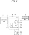
- FIG. 2 is a circuit diagram illustrating a circuit configuration of a disconnection detection unit 120 and a sensing voltage generation unit 130 in a protective relay according to an embodiment of the present disclosure.
- FIG. 3 is a block diagram for explaining a configuration of a disconnection determination unit 150 in a protective relay according to an embodiment of the present disclosure.
- the protective relay 10 may include the disconnection detection unit 120 disposed to be connected to the transformation unit 110, the sensing voltage generation unit 130 that applies a predetermined voltage to the disconnection detection unit 120, and the disconnection determination unit 150 capable of determining a circuit connection state to the transformation unit 110 based on a voltage signal detected at the disconnection detection unit 120.
- the transformation unit 110 which is a device that converts a voltage or current input from a power system into a voltage or current at a lower level, may include a potential transformer (PT) or a current transformer (CT).
- PT potential transformer
- CT current transformer
- the potential transformer may be a potential transformer using a resistance voltage dividing method or a potential transformer using an iron core according to a voltage conversion method.
- the current transformer may be a current transformer using an iron core or a Rogowski coil type current transformer using an air core according to a current conversion method.
- the disconnection detection unit 120 may include nodes respectively connected to both output ends of the transformation unit 110. Accordingly, a circuit may be configured when both output ends of the transformation unit 110 are connected to the nodes, and the circuit between the nodes may be disconnected when the transformation unit 110 is disconnected.
- either one of the nodes (hereinafter referred to as a first node 111) may be connected to the disconnection determination unit 150, and the other node (hereinafter referred to as a second node 112) may be connected to the sensing voltage generation unit 130.
- the disconnection detection unit 120 may include a plurality of resistors (R1, R2, R3) 125, 126, 127 constituting a voltage dividing resistor.
- the first resistor (R1) 125 of the plurality of resistors (R1, R2, R3) 125, 126, 127 may be connected to a first contact (n1) 121 disposed between the first node 111 and the disconnection determination unit 150. Furthermore, the third resistors (R3) 127 may be connected to a third contact (n3) 123 disposed between the second node 112 and the sensing voltage generation unit 130.
- the first contact (n1) 121 and the third contact (n3) 123 may be connected to each other. Furthermore, a second contact (n2) 122 may be disposed in an electrical circuit connecting between the first contact (n1) 121 and the third contact (n3) 123.
- the first resistor (R1) 125 may be disposed between the first contact (n1) 121 and the second contact (n2) 122
- the second resistor (R2) 126 may be disposed between the second contact (n2) 122 and the third contact (n3) 123.
- the second contact (n2) 122 may be connected to a reference voltage generation unit 129 that provides a reference voltage to the disconnection detection unit 120.
- Another resistor (second resistor (R2) 126) constituting the voltage dividing resistor may be disposed between the second contact (n2) 122 and the reference voltage generation unit 129.
- the reference voltage generation unit 129 may be configured with a ground that provides a ground voltage as the reference voltage.
- a circuit in which the first contact (n1) 121 and the third contact (n3) 123 are connected to each other may be configured. Therefore, a predetermined voltage applied through the sensing voltage generation unit 130 may be applied to the first contact (n1) 121.
- the first contact (n1) 121 and the third contact (n3) 123 are disconnected from each other. Accordingly, a voltage signal having a difference between a voltage applied from the sensing voltage generation unit 130 and a voltage applied from the reference voltage generation unit 129, and a voltage divided by a plurality of resistors constituting the voltage dividing resistor may be applied to the first contact (n1) 121.
- the disconnection determination unit 150 detects a voltage signal of the first contact (n1) 121 connected to the first node 111, the detected voltage signal may vary according to a circuit connection state between the first node 111 and the second node 112, that is, whether the transformation unit 110 is disconnected.
- the sensing voltage generation unit 130 may apply a voltage for defining a predetermined voltage difference with respect to the reference voltage to the disconnection detection unit 120.
- the sensing voltage generation unit 130 may be disposed to provide a voltage at a different magnitude from that of the reference voltage generation unit 129 of the disconnection detection unit 120.
- the sensing voltage generation unit 130 may be configured to provide a voltage different from the ground voltage.
- the sensing voltage generation unit 130 may further include a voltage generation unit 131 for applying a predetermined direct current (DC) voltage to the disconnection detection unit 120 in addition to a ground 132.
- DC direct current
- a voltage applied by the sensing voltage generation unit 130 will be referred to as 'VR'.
- the sensing voltage generation unit 130 may of course be configured in a ground form to provide a ground voltage.
- the reference voltage generation unit 129 and the sensing voltage generation unit 130 may also be respectively configured to apply a predetermined voltage greater than the ground voltage. In this case, the reference voltage generation unit 129 and the sensing voltage generation unit 130 may be configured to apply different DC voltages.
- the disconnection determination unit 150 may determine whether a circuit disconnection has occurred by the transformation unit 110 based on a voltage signal detected by the disconnection detection unit 120.
- the disconnection determination unit 150 may include a control unit 155, a conversion unit 156 connected to the control unit 155, a plurality of determination units (a first determination unit 151, a second determination unit 152, a third determination unit 153), and a memory 158.
- the disconnection determination unit 150 may further include an output unit 157 for outputting a result of determining whether a circuit is disconnected.
- the conversion unit 156 may convert an analog voltage signal detected by the disconnection detection unit 120 into a signal that can be identified by the disconnection determination unit 150.
- the conversion unit 156 may be an analog-to-digital converter (ADC).
- a range of a voltage signal that can be processed by the conversion unit 156 may be limited. Accordingly, the disconnection detection unit 120 may be configured such that a voltage signal within a range that can be processed by the conversion unit 156 is input to the conversion unit 156.
- the reference voltage generation unit 129 and the sensing voltage generation unit 130 may be configured to input different voltage signals of 0 to 3.3 V to the transformation unit 110 when the circuit is normally connected and when the circuit is disconnected.
- the reference voltage generation unit 129 and the sensing voltage generation unit 130 may be configured to input a voltage signal having a center voltage of 1.65 V to the conversion unit 156.
- the reference voltage generation unit 129 and the sensing voltage generation unit 130 of the disconnection detection unit 120 may be configured to input a voltage signal having a voltage less than (when a voltage of the reference voltage generation unit 129 is less than that of the sensing voltage generation unit 130) or greater than (when a voltage of the reference voltage generation unit 129 is greater than that of the sensing voltage generation unit 130) the 1.65 V to the conversion unit 156.
- the memory 158 may store data supporting a function of the disconnection determination unit 150.
- the memory 158 may store data and instructions related to an application program driven by the first determination unit 151, the second determination unit 152, and the third determination unit 153 provided in the disconnection determination unit 150.
- information on a preset threshold voltage may be stored as data for the determination of the first determination unit 151, and information on a resistance of the second resistor (R2) 126, a resistance of the third resistor (R3) 127, a voltage of the reference voltage generation unit 129 constituting the voltage dividing resistor, and a magnitude of a voltage according to a design margin may be stored as data for the determination of the second determination unit 152, in the memory 158.
- data for the determination of the third determination unit 153 information on a minimum AC current component that can be detected during the occurrence of a fault current such as a short-circuit current or an in-rush current of the transformation unit 110, that is, a magnitude of a fault current signal, may be stored.
- control unit 155 may be configured to control other elements connected thereto, and may control an overall operation of the disconnection determination unit 150.
- the control unit 155 may acquire a DC offset value from the converted voltage signal.
- the control unit 151 may control the first determination unit 151 to compare a magnitude of the acquired DC offset value with a magnitude of a preset threshold voltage.
- a magnitude of a voltage applied to the first contact 121 may be less than (when a voltage of the reference voltage generation unit 129 is less than that of the sensing voltage generation unit 130) or greater than (when a voltage of the reference voltage generation unit 129 is greater than that of the sensing voltage generation unit 130) that when the circuit connected to the transformation unit 110 is normal.
- the control unit 155 may determine whether the circuit connected to the transformation unit 110 is disconnected according to the comparison result of the first determination unit 151.
- the control unit 155 may determine whether a difference between the acquired DC offset value and the threshold voltage is within a preset error range.
- control unit 155 may reflect a preset margin value to the acquired DC offset value. Furthermore, the control unit 155 may control the second determination unit 152 to compare a magnitude of the acquired DC offset value to which the margin value is reflected with the threshold voltage again.
- the control unit 155 may determine that a difference between the DC offset value and the threshold voltage is out of a preset error range.
- control unit 155 may determine again that the circuit connected to the transformation unit 110 is disconnected.
- a disconnection determination result according to the second determining unit 152 will be referred to as a secondary disconnection determination result.
- a magnitude of a voltage signal having a DC component detected by the disconnection detection unit 120 may be changed though the in-rush current or the short-circuit current is an AC component. Accordingly, when the in-rush current or the short-circuit current is generated even though the circuit is not disconnected, the magnitude of the voltage signal detected at the first contact 121 may decrease or increase by a predetermined level or more.
- control unit 155 may determine whether the determination result is due to the generation of the in-rush current or the short-circuit current.
- control unit 155 may detect a magnitude of an alternating current (AC) component signal by calculating a root mean square (RMS) value from a voltage signal converted by the conversion unit 156. Then, the control unit 155 may control the third determination unit 153 to determine whether the detected AC signal component is greater than a preset signal magnitude of a fault current.
- AC alternating current
- RMS root mean square
- the fault current may denote the short-circuit current or the in-rush current of the transformation unit.
- the preset signal magnitude of the fault current may be determined as a minimum magnitude of an AC signal component that can be detected by the disconnection detection unit 120 when the short-circuit current or the in-rush current of the transformation unit is generated.
- the signal magnitude of the fault current may be preset by a user or may be determined based on a result of a number of repeated experiments performed in connection with the present disclosure.
- the control unit 155 may determine that the short-circuit current or the in-rush current is not generated. Accordingly, the control unit 155 may determine that a current disconnection state of the circuit is not due to the short-circuit current or the in-rush current, and finally determine that the circuit connected to the transformation unit 110 is disconnected.
- control unit 155 may control the output unit 157 to transmit an alarm signal indicating a disconnection state of the circuit to the user.
- control unit 155 may output an alarm signal as an audible signal or a visible signal through the output unit 157.
- the control unit 155 may transmit the alarm signal to another preset device, for example, the user's mobile terminal, or the like, through the output unit 157, and control the mobile terminal to output an alarm signal, thereby transferring the alarm signal to the user.
- the output unit 157 may include a communication function for transmitting the alarm signal.
- FIGS. 4 to 8 are diagrams for explaining an operation process of the disconnection determination unit 150 configured to determine whether a circuit is disconnected by the transformation unit 110 according to a voltage signal detected from the disconnection detection unit 120 in the protective relay 10 according to an embodiment of the present disclosure.
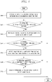
- FIG. 4 is a flowchart illustrating an operation process of the disconnection determination unit 150
- FIG. 5 is a diagram illustrating a magnitude of a voltage signal detected by the disconnection detection unit 120 when the transformation unit 110 is normally connected in the protective relay 10 according to an embodiment of the present disclosure
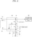
- FIG. 6 is a diagram illustrating a magnitude of a voltage signal detected by the disconnection detection unit 120 when the transformation unit 110 is disconnected in the protective relay 10 according to an embodiment of the present disclosure.
- FIG. 7 is an exemplary diagram illustrating a difference in DC offset value detected by the disconnection detection unit between when the transformation unit is normally connected and when disconnected in the protective relay 10 according to an embodiment of the present disclosure
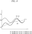
- FIG. 8 is an exemplary diagram illustrating an example of an in-rush current or a short-circuit current of the transformation unit 110 having a negative voltage flowing in from the transformation unit.
- control unit 155 of the disconnection determination unit 150 provided in the protective relay 10 may repeatedly perform an operation process of determining whether the transformation unit 110 is disconnected according to a preset period as shown below in FIG. 4 .
- the preset period may be a period corresponding to a period of a signal input to the transformation unit 110 from a line, and in this case, an operation process as shown below in FIG. 4 may be performed every time a main operation of the protective relay 10 is carried out.
- the main operation of the protective relay 10 may vary depending on a device connected to the protective relay 10.
- the main operation may be a relay operation when a device connected to the protective relay 10 is a digital relay, and may be a measurement operation when the connected device is a digital measuring instrument.
- the main operation may be a power conversion operation.
- the control unit 155 may convert the voltage signal through the conversion unit 156, and extract a value of a direct current (DC) component, that is, a DC offset value, from the converted sampling digital data of one cycle (S400).
- DC direct current
- control unit 155 may control the first determination unit 151 to compare the extracted DC offset value with a preset threshold voltage to primarily determine whether a circuit is disconnected (S402).
- a circuit in which the third contact 123 and the first contact 121 are connected through the transformation unit 110 may be configured when the circuit connected to the transformation unit 110 is in a normal state. Therefore, as shown in FIG. 5 , a reference voltage VR of the sensing voltage generation unit 130 connected to the third contact 123 may be applied to the first contact 121 through the transformation unit 110.
- a voltage of the first contact (n1) 121 may be the same as that applied to the third contact (n3) 123. Therefore, in a case where the circuit is normally connected to the transformation unit 110, when the reference voltage VR is applied to the third contact (n3) 123, the reference voltage VR that is the same as that applied to the third contact (n3) 123 may be applied to the first contact (n1) 121. Accordingly, a DC offset value of a voltage signal corresponding to the reference voltage VR may be extracted through the conversion unit 156.
- n1(v) is a magnitude of a voltage signal applied to the first contact 121
- n2(v) is a magnitude of a voltage signal applied to the second contact 122.
- a voltage signal determined by a voltage dividing resistor consisting of the second resistor (R2) 126 and the third resistor (R3) 127 and the reference voltage VR applied from the sensing voltage generation unit 130 may be applied to the second contact (n2) 122.
- Equation 2 below shows a magnitude of the voltage signal applied to the second contact (n2) 122 according to the voltage dividing resistor and the reference voltage VR.
- n 2 V VR ⁇ R 2 R 2 + R 3
- n2(v) is a magnitude of a voltage signal applied to the second contact 122
- VR is a reference voltage
- R2 is a resistance value of the second resistor (R2) 126
- R3 is a resistance value of the third resistor (R3) 127.
- n2(v) has a magnitude according to the product of a value less than 1 and the reference voltage VR, and thus always has a value smaller than the reference voltage VR. Therefore, as shown in FIG. 7 , a magnitude 700 of the DC offset value extracted when the connection of the circuit is in a normal state may always have a value greater than a magnitude 702 of the DC offset value extracted when the connection of the circuit is in a disconnected state.
- the control unit 155 may primarily determine that the circuit connected to the current transformation unit 110 is disconnected.
- the control unit 155 may determine that the circuit is not disconnected. Furthermore, when it is determined that the circuit is not disconnected as a result of the determination in the step S402, the control unit 155 may end a disconnection determination process in a current period.
- the control unit 155 may add a voltage value according to a design margin to the currently extracted DC offset value (S404).
- the voltage value according to the design margin may further include a preset error value.
- the error value may be a measurement error, and may further include an error that may occur in a conversion process of the conversion unit 156.
- control unit 155 controls the second determination unit 152 to compare the summed voltage value with the threshold voltage again (S406).
- control unit 155 may determine that the circuit is in a non-disconnected state. Furthermore, when it is determined that the circuit is not disconnected as a result of the determination in the step S406, the control unit 155 may end a disconnection determination process in a current period.
- control unit 155 may determine again that the circuit currently connected to the transformation unit 110 is disconnected (secondary disconnection determination).
- control unit 155 may determine whether a difference between the DC offset value and the threshold voltage is caused by a short-circuit current or an in-rush current according to the start-up of the transformation unit 110.
- the short-circuit current or the in-rush current is generated when the circuit is short-circuited or the transformation unit 110 is started, and refers to a very large and temporarily generated current that is several times higher than that of a normal operation state of the transformation unit 110.
- the short-circuit current or the in-rush current has a pattern in which the magnitude gradually decreases after an instantaneous large current flows.
- the short-circuit current or the in-rush current may have a positive voltage, as well as have a negative value compared to a normal case 800 in a voltage graph (an AC component 810 and a DC component 820) as shown in FIG. 8 .
- a DC component applied from the sensing voltage generation unit 130 that is, a value of the reference voltage (VR) may be decreased.
- a magnitude of a voltage signal applied to the first contact (n1) 121 may be lowered, and as a result, the magnitude of the voltage signal detected at the first contact 121 may be detected to be lower than the threshold voltage (VR).
- the control unit 155 of the protective relay 10 may further detect a magnitude of an alternating current (AC) component from the sampling digital data of one cycle converted by the conversion unit 156 when it is determined that the circuit is disconnected as a result of the secondary disconnection determination of the step S406 (S408).
- the control unit 155 may detect the magnitude of the AC component using a method of calculating a root mean square (RMS) or the like.
- the detected magnitude of the AC component may be compared with a preset fault current signal magnitude (S410).
- the control unit 155 may determine that a short-circuit current or an in-rush current according to the start-up of the transformation unit 110 has occurred. In addition, it may be determined that the disconnection state of the circuit according to a result of the determination (secondary disconnection determination) in the step S406 is erroneously determined due to the occurrence of the short-circuit current or the in-rush current.
- control unit 155 may determine that the circuit is normally connected despite the secondary disconnection determination result. Accordingly, the control unit 155 may end a process of determining whether the circuit is disconnected in a current period without outputting an alarm signal or the like.
- the control unit 155 may determine that a short-circuit current or an in-rush current according to the start-up of the transformation unit 110 has not occurred. Accordingly, the control unit 155 may finally determine that the circuit currently connected to the transformation unit 110 is disconnected, and may output an alarm signal for transferring the disconnection of the circuit to the user (S412).
- the protective relay 10 may determine once again whether the voltage signal is included in an error range using a preset margin voltage. Accordingly, it may be possible to prevent in advance a disconnection state of the circuit from being erroneously determined due to a measurement error or a design error.
- the protective relay 10 may detect whether a short-circuit current or an in-rush current is generated based on a magnitude of an AC component signal detected from the voltage signal, thereby further determining whether the voltage signal is affected by the short- circuit current or the in-rush current. Accordingly, it may be possible to prevent in advance a disconnection state of the circuit from being erroneously determined due to the effect of the short-circuit current or the in-rush current.
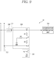
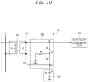
- FIGS. 9 to 12 are drawings illustrating examples in which the foregoing various types of transformation units 110 are connected to the protective relay 10 according to an embodiment of the present disclosure.
- FIG. 9 shows an example in which the protective relay 10 according to an embodiment of the present disclosure is connected to a resistance voltage dividing type potential transformer as the transformation unit 110.
- a resistor for voltage conversion may serve as the transformation unit 110. Therefore, either one of the first and second nodes 111, 112 of the disconnection detection unit may be connected to the resistor 110 for voltage conversion, and the other node may be directly connected to the line. Then, a circuit of the disconnection detection unit 120 may be configured through the lines L, N and the resistor 110.
- FIG. 10 shows an example in which the protective relay 10 according to an embodiment of the present disclosure is connected to a potential transformer (PT) using an iron core as the transformation unit 110.
- PT potential transformer
- the first and second nodes 111, 112 of the disconnection detection unit may be connected to both ends of the potential transformer (PT) 110, respectively, to configure a circuit of the disconnection detection unit 120 connected through the potential transformer (PT) 110.
- FIG. 11 shows an example in which the protective relay 10 according to an embodiment of the present disclosure is connected to a current transformer (CT) using an iron core as the transformation unit 110.
- CT current transformer
- the first and second nodes 111, 112 of the disconnection detection unit may be connected to both ends of the current transformer (CT) 110, respectively, to configure a circuit of the disconnection detection unit 120 connected through the current transformer (CT) 110.
- FIG. 12 shows an example in which the protective relay 10 according to an embodiment of the present disclosure is connected to a current transformer using a Rogowski coil as the transformation unit 110.
- the first and second nodes 111, 112 of the disconnection detection unit may be connected to both ends of the Rogowski coil, respectively, to configure a circuit of the disconnection detection unit 120 connected through the Rogowski coil.
- the integration circuit may be further included between the disconnection detection unit 120 and the disconnection determination unit 150.
- the disconnection determination unit 150 may further include an integrator (not shown) that performs integration according to a preset integration algorithm to restore the delayed waveform.
- a noise filter circuit or a digital filter for removing noise may be further provided in the disconnection determination unit 150, and the transformation unit 110 and the disconnection detection unit 120 may be designed to have a structure that allows the Rogowski coil and the cable passing through the Rogowski coil to be constantly maintained.
- the disconnection detection unit 120 may be configured to further include a voltage dividing resistor.
- the disconnection detection unit 120 has a circuit structure constituting a voltage dividing resistor configured with the first resistor (R1) 125, the second resistor (R2) 126, and the third resistor (R3) 127, but any one of the first to third resistors 125, 126, 127 may of course be omitted.
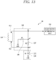
- FIGS. 13 to 14 are exemplary diagrams illustrating examples of the disconnection detection unit 120 having a structure in which any one of resistors constituting a voltage dividing resistor is omitted as described above in the protective relay 10 according to an embodiment of the present disclosure.
- FIG. 13 shows an example in which the first resistor (R1) 125 is omitted or a resistance value of the first resistor (R1) 125 is 0 ohm.
- the first resistor (R1) 125 is provided to prevent a voltage applied to the second contact (n2) 122 from being applied to the first contact (n1) 121, thereby preventing an excessive voltage from being applied to the disconnection determination unit 150, that is, the conversion unit 156, due to being connected to the first contact (n1) 121 when the excessive voltage is applied to the second contact (n2) 121.
- the disconnection detection unit 120 may have a structure in which the first resistor (R1) 125 is omitted.
- FIG. 14 shows an example in which the second resistor (R2) 126 is omitted or a resistance value of the second resistor (R2) 126 is 0 ohm.
- the magnitude of the voltage signal applied to the second contact (n2) 122 may be 0 V. Furthermore, when the magnitude of the voltage signal applied to the second contact (n2) 122 is 0 V, the magnitude of the voltage signal applied to the first contact (n1) 121 may also be 0 V when the circuit is in a disconnected state.
- a magnitude of a voltage signal applied to the first contact (n1) 121 may be the reference voltage VR that is the same as that of a voltage signal applied to the third contact (n3) 123 as described above. Therefore, when the second resistor (R2) 126 is omitted, a difference between the DC offset value in a normal circuit state and the DC offset value in a disconnection state, which are detected through the conversion unit 156, may have a large drop to 0 V from the reference voltage VR.
- the conversion unit 156 must be able to receive a voltage signal of 0 V from the reference voltage VR. That is, when an input signal range of the conversion unit 156 includes a range between the reference voltage VR and 0 V, as shown in FIG. 14 , the disconnection detection unit 120 may have a structure in which the second resistor (R2) 126 is omitted.
- the reference voltage generation unit 129 has a ground voltage as an example.
- the reference voltage generation unit 129 may also of course be configured to further include a separate voltage generation unit 1500 to have a higher voltage than the ground.
- FIG. 15 is a circuit diagram illustrating an example of the disconnection detection unit 120 having a structure in which the reference voltage generation unit 129 further includes a separate voltage generation unit that applies a preset voltage instead of the ground voltage as described above in the protective relay 10 according to the embodiment of the present disclosure.
- a reference voltage generated by the reference voltage generation unit 129 may be determined according to the separately connected voltage generation unit 1500. Accordingly, in the following description, it is assumed that a voltage of the reference voltage generation unit 129 is a voltage VS of the added voltage generation unit 1500.
- the voltage VR applied from the sensing voltage generation unit 130 will be referred to as a first reference voltage
- the voltage VS of the reference voltage generation unit as a second reference voltage
- n1(v) is a magnitude of a voltage signal applied to the first contact 121
- n3(v) is a magnitude of a voltage signal applied to the third contact 123
- VR is the first reference voltage
- a voltage signal that is the same as that applied to the second contact (n2) 122 may be applied to the first contact (n1) 121 connected to the disconnection determination unit 150. Accordingly, a voltage signal having a voltage in which a voltage difference between the second reference voltage VS and the first reference voltage VR is divided by the second resistor (R2) 126 and the third resistor (R3) 127 may be applied to the second contact (n2) 122.
- Equation 4 represents a magnitude of a voltage signal applied to the second contact (n2) 122 in this case.
- n 2 V VR ⁇ VS ⁇ R 2 R 2 + R 3 , if , VS ⁇ VR
- n2(v) is a magnitude of a voltage signal applied to the second contact 122
- VR is a first reference voltage
- VS is a second reference voltage
- R2 is a resistance value of the second resistor (R2) 126
- R3 is a resistance value of the third resistor (R3) 127.
- the DC offset value (voltage) detected from a voltage signal detected at the first contact (n1) 121 when the circuit is in a disconnected state may be less than that extracted from the voltage signal VR detected at the first contact (n1) 121 when the circuit is in a normal state.
- a voltage signal applied to the second contact (n2) 122 may have a voltage greater than the first reference voltage VR as shown below in Equation 5.
- n 2 V VR + VS ⁇ VR ⁇ R 2 R 2 + R 3 , if , VS > VR
- n2(v) is a magnitude of a voltage signal applied to the second contact 122
- VR is a first reference voltage
- VS is a second reference voltage
- R2 is a resistance value of the second resistor (R2) 126
- R3 is a resistance value of the third resistor (R3) 127.
- a DC offset value detected from a voltage signal detected at the first contact (n1) 121 when the circuit is in a disconnected state may be greater than that extracted from a voltage signal VR detected at the first contact (n1) 121 when the circuit is in a normal state.
- control unit 155 may determine that the circuit is disconnected when the DC offset value extracted from the voltage signal detected by the disconnection detection unit 120 has a value less than the threshold voltage VR, but determine that the circuit is disconnected when the DC offset value has a value greater than the threshold voltage VR.
- FIG. 16 is a flowchart illustrating an operation process of the disconnection determination unit 150 configured to determine whether the transformation unit 110 is disconnected according to a voltage signal detected from the disconnection detection unit 120 in the protective relay 10 according to an embodiment of the present disclosure, in this case.
- the second reference voltage VS has a value greater than the first reference voltage VR.
- the control unit 155 may extract a value of a direct current (DC) component, that is, a DC offset value, from the sampling digital data of one cycle that has been converted through the conversion unit 156 (S1600).
- DC direct current
- control unit 155 may control the first determination unit 151 to compare the extracted DC offset value with a preset threshold voltage to primarily determine whether a circuit is disconnected (S1602).
- a circuit in which the third contact 123 and the first contact 121 are connected through the transformation unit 110 may be configured when the circuit connected to the transformation unit 110 is in a normal state. Therefore, a reference voltage VR of the sensing voltage generation unit 130 connected to the third contact 123 may be applied to the first contact 121 through the transformation unit 110. Therefore, a DC offset value of a voltage signal corresponding to the reference voltage VR may be extracted through the conversion unit 156.
- the first contact 121 and the third contact 121 may not be connected between each other. Then, the same voltage signal as that of the second contact 122 may be applied to the first contact 121 as shown above in Equation 3.
- a voltage signal having a voltage in which a voltage difference between the second reference voltage VS and the first reference voltage VR is divided by the second resistor (R2) 126 and the third resistor (R3) 127 may be applied to the second contact (n2) 122.
- the second reference voltage VS has a value greater than the first reference voltage VR as described above, as shown above in Equation 5, a magnitude of the voltage signal applied to the second contact (n2) 122 may be calculated according to a voltage difference between the second reference voltage VS and the first reference voltage VR, the second resistor (R2) 126, and the third resistor (R3) 127.
- a voltage signal having a voltage greater than the first reference voltage VR may be applied to the second contact (n2) 122. Therefore, a magnitude of the DC offset value extracted when the connection of the circuit is in a disconnected state may have a value greater than that of the DC offset value extracted when the connection of the circuit is in a normal state.
- a DC offset value extracted in the step S1600 may have a value greater than the threshold voltage (first reference voltage VR). Therefore, as a result of the determination in step S1602, when a magnitude of the currently extracted DC offset value is greater than the threshold voltage, the control unit 155 may primarily determine that the circuit connected to the current transformation unit 110 is disconnected.
- the control unit 155 may determine that the circuit is not disconnected. Furthermore, when it is determined that the circuit is not disconnected as a result of the determination in the step S1602, the control unit 155 may end a disconnection determination process in a current period.
- the control unit 155 may subtract a voltage value according to a design margin from the currently extracted DC offset value (S1604).
- the voltage value according to the design margin may further include a preset error value.
- the error value may be a measurement error, and may further include an error that may occur in a conversion process of the conversion unit 156.
- control unit 155 may control the second determination unit 152 to compare a voltage value from which the design margin is subtracted with the threshold voltage again (S1606).
- control unit 155 may determine that the circuit is in a non-disconnected state. Furthermore, when it is determined that the circuit is not disconnected as a result of the determination in the step S1606, the control unit 155 may end a disconnection determination process in a current period.
- control unit 155 may determine again that the circuit currently connected to the transformation unit 110 is disconnected (secondary disconnection determination).
- control unit 155 may further detect a magnitude of the AC component from the sampling digital data of one cycle converted through the conversion unit 156 (S1608).
- the detected magnitude of the AC component may be compared with a preset fault current signal magnitude (S1610).
- the control unit 155 may determine that a short-circuit current or an in-rush current according to the start-up of the transformation unit 110 has occurred. In addition, it may be determined that the disconnection state of the circuit according to a result of the determination (secondary disconnection determination) in the step S1606 is erroneously determined due to the occurrence of the short-circuit current or the in-rush current.
- control unit 155 may determine that the circuit is normally connected despite the secondary disconnection determination result. Accordingly, the control unit 155 may end a process of determining whether the circuit is disconnected in a current period without outputting an alarm signal or the like.
- the control unit 155 may determine that a short-circuit current or an in-rush current according to the start-up of the transformation unit 110 has not occurred. Accordingly, the control unit 155 may finally determine that the circuit currently connected to the transformation unit 110 is disconnected, and may output an alarm signal for transferring the disconnection of the circuit to the user (S1612).
- the operation process of FIG. 16 may be repeatedly carried out according to a preset period.
- the preset period may be a period corresponding to a period of a signal input to the transformation unit 110 from a line, and in this case, an operation process as shown above in FIG. 16 may be performed every time a main operation of the protective relay 10 is carried out.
- the main operation of the protective relay 10 may vary depending on a device connected to the protective relay 10.
- the main operation may be a relay operation when a device connected to the protective relay 10 is a digital relay, and may be a measurement operation when the connected device is a digital measuring instrument.
- the main operation may be a power conversion operation.
- FIGS. 17 and 18 are exemplary diagrams illustrating a circuit structure of the disconnection detection unit 120 when any one of the resistors constituting the voltage dividing resistor is omitted in the protective relay 10 having the structure shown in FIG. 15
- FIG. 17 shows an example in which the first resistor (R1) 125 is omitted or a resistance value of the first resistor (R1) 125 is 0 ohm.
- the first resistor (R1) 125 it is provided to prevent a voltage applied to the second contact (n2) 122 from being applied to the first contact (n1) 121, thereby preventing an excessive voltage from being applied to the disconnection determination unit 150, that is in the case of conversion unit 156, due to being connected to the first contact (n1) 121 when the excessive voltage is applied to the second contact (n2) 121.
- a voltage difference between the first reference voltage VS and the second reference voltage VR may divided by the second resistor (R2) 126 and the third resistor (R3) 127 to be applied.
- the first reference voltage VS is less than the second reference voltage VR
- a maximum voltage that can be applicable to the first contact (n1) 121 may correspond to the first reference voltage VR.
- the disconnection detection unit 120 may have a structure in which the first resistor (R1) 125 is omitted.
- the first reference voltage VS when the first reference voltage VS is greater than the second reference voltage VR, a signal having a voltage greater than that of the first reference voltage VR may be applied to the first contact (n1) 121 when the circuit is disconnected. Therefore, as shown in FIG. 17 , in order to have a structure in which the first resistor (R1) 125 is omitted, not only the first reference voltage VR but also the second reference voltage VS must have a voltage having an appropriate magnitude, that is, a magnitude that does not damage the conversion unit 156.
- FIG. 18 shows an example in which the second resistor (R2) 126 is omitted or a resistance value of the second resistor (R2) 126 is 0 ohm in a circuit of the disconnection detection unit 120 illustrated in FIG. 15 .
- the magnitude of the voltage signal applied to the second contact (n2) 122 may be 0 V. Furthermore, when the magnitude of the voltage signal applied to the second contact (n2) 122 is 0 V, the magnitude of the voltage signal applied to the first contact (n1) 121 may also be 0 V when the circuit is in a disconnected state.
- the magnitude of the voltage signal applied to the first contact (n1) 121 may be the first reference voltage VR as described above. Therefore, when the second resistor (R2) 126 is omitted, a difference between the DC offset value in a normal circuit state and the DC offset value in a disconnection state, which are detected through the conversion unit 156, may have a large drop to 0 V from the first reference voltage VR.
- the conversion unit 156 must be able to receive a voltage signal of 0 V from the first reference voltage VR. That is, when an input signal range of the conversion unit 156 includes a range between the first reference voltage VR and 0 V, as shown in FIG. 18 , the disconnection detection unit 120 further including the second reference voltage VS may have a structure in which the second resistor (R2) 126 is omitted.
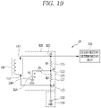
- FIG. 19 is a circuit diagram illustrating a structure of the sensing voltage generation unit 130 having a structure that applies a ground voltage as the first reference voltage instead of a preset voltage in the protective relay 10 according to an embodiment of the present disclosure.
- the reference voltage generation unit 129 when the sensing voltage generation unit 130 applies a ground voltage as the first reference voltage, the reference voltage generation unit 129 must further include a separate voltage generation unit 1500 to provide a second reference voltage different from the ground voltage.
- the first reference voltage VR applied from the sensing voltage generation unit 130 may be a ground voltage (0 V)
- the voltage VS applied from the voltage generation unit 1500 may be a second reference voltage.
- a voltage signal that is the same voltage signal as a magnitude of a voltage signal applied to the third contact (n3) 123 may be applied to the first contact (n1) 121.
- a signal of the first reference voltage that is, a ground voltage
- a ground voltage that is, a voltage signal of 0 V
- a magnitude of a voltage signal applied to the first contact (n1) 121 may be determined according to a magnitude of a voltage signal applied to the second contact (n2) 122, as shown above in Equations 4 and 5. Accordingly, when the circuit is disconnected, a voltage signal having a voltage greater than a first reference voltage, that is, a ground voltage, may be applied to the first contact (n1) 121.
- control unit 155 of the disconnection determination unit 150 may primarily determine whether the circuit is disconnected according to whether a DC offset value acquired through the conversion unit 156 from a voltage signal of the first contact (n1) 121 detected by the disconnection detection unit 120 is greater than the ground voltage. Furthermore, a secondary disconnection determination may be made by reflecting a design margin according to the primary disconnection determination result, and whether the circuit is disconnected may be finally determined based on a magnitude of an AC component acquired through the conversion unit 156 from a voltage signal of the first contact (n1) 121 according to the secondary disconnection determination result.
- the first determination unit 151 and the second determination unit 152 may be determination units that compare a DC offset value acquired through the conversion unit 156 and a value obtained by reflecting a design margin to the DC offset value, respectively, with a preset threshold.
- the control unit 150 instead of the second determination unit 152 may of course calculate a value obtained by reflecting the design margin to a preset threshold voltage.
- the first determination unit 151 and the second determination unit 152 may of course be integrated into one determination unit that compare a value specified by the control unit 155 (a DC offset value acquired through the conversion unit 156 or a value obtained by reflecting a design margin to the acquired DC offset value) with a preset threshold voltage.
- the integrated one determination unit may sequentially compare a DC offset value obtained through the conversion unit 156 and a value obtained by reflecting a design margin to the DC offset value with a preset threshold voltage under the control of the control unit 155 to perform the first disconnection determination and the second disconnection determination.
- the present disclosure described above may be implemented as computer-readable codes on a program-recorded medium.
- the computer-readable medium includes all kinds of recording devices in which data readable by a computer system is stored. Examples of the computer-readable medium include a hard disk drive (HDD), a solid state disk (SSD), a silicon disk drive (SDD), a ROM, a RAM, a CD-ROM, a magnetic tape, a floppy disk, an optical data storage device and the like, and also include a device implemented in the form of a carrier wave (for example, transmission via the Internet).
- the computer may include the control unit 155 of the disconnection determination unit 150.
Landscapes
- Engineering & Computer Science (AREA)
- Power Engineering (AREA)
- Testing Of Short-Circuits, Discontinuities, Leakage, Or Incorrect Line Connections (AREA)
- Emergency Protection Circuit Devices (AREA)
- Protection Of Static Devices (AREA)
Applications Claiming Priority (3)
| Application Number | Priority Date | Filing Date | Title |
|---|---|---|---|
| KR20190165893 | 2019-12-12 | ||
| KR1020200128167A KR102485653B1 (ko) | 2019-12-12 | 2020-10-05 | 보호 계전기 및 그 보호 계전기의 단선 검출 방법 |
| PCT/KR2020/015602 WO2021118071A2 (ko) | 2019-12-12 | 2020-11-09 | 보호 계전기 및 그 보호 계전기의 단선 검출 방법 |
Publications (2)
| Publication Number | Publication Date |
|---|---|
| EP4075619A2 true EP4075619A2 (de) | 2022-10-19 |
| EP4075619A4 EP4075619A4 (de) | 2024-01-17 |
Family
ID=76329123
Family Applications (1)
| Application Number | Title | Priority Date | Filing Date |
|---|---|---|---|
| EP20899162.0A Pending EP4075619A4 (de) | 2019-12-12 | 2020-11-09 | Schutzrelais und verfahren zum detektieren der trennung eines schutzrelais |
Country Status (5)
| Country | Link |
|---|---|
| US (1) | US11695267B2 (de) |
| EP (1) | EP4075619A4 (de) |
| JP (1) | JP7417737B2 (de) |
| CN (1) | CN114830480B (de) |
| WO (1) | WO2021118071A2 (de) |
Families Citing this family (1)
| Publication number | Priority date | Publication date | Assignee | Title |
|---|---|---|---|---|
| CN118858933B (zh) * | 2024-09-26 | 2025-01-24 | 宁德时代新能源科技股份有限公司 | 检测电路、继电器检测系统以及继电器检测方法 |
Family Cites Families (19)
| Publication number | Priority date | Publication date | Assignee | Title |
|---|---|---|---|---|
| KR100479692B1 (ko) * | 2002-09-30 | 2005-04-06 | 주식회사 젤파워 | 변압기 보호용 충격 압력계전 시스템의 오동작 방지장치 |
| KR100873774B1 (ko) * | 2007-05-11 | 2008-12-15 | 박이락 | 자기진단회로가 내장된 변류기 |
| KR100902471B1 (ko) | 2007-09-14 | 2009-06-11 | 엘에스산전 주식회사 | 디지털 보호 계전기의 전력량 오차 보상장치 |
| JP4926015B2 (ja) * | 2007-12-05 | 2012-05-09 | 三菱電機株式会社 | 漏電リレー |
| KR100860865B1 (ko) * | 2008-07-09 | 2008-09-29 | 와이피피디지텍(주) | 추가 전력 인입선을 이용한 전자식 전력량계용 변류기의2차측 코일 단선 자기진단장치 |
| JP2010148284A (ja) * | 2008-12-19 | 2010-07-01 | Chugoku Electric Power Co Inc:The | 保護継電システム |
| CN101794682B (zh) * | 2010-02-02 | 2012-07-25 | 浙江南瑞科技有限公司 | 框架断路器智能控制器 |
| JP5578888B2 (ja) * | 2010-03-09 | 2014-08-27 | 株式会社東芝 | 電流差動継電装置 |
| WO2012090036A1 (en) * | 2010-12-31 | 2012-07-05 | Abb Technology Ltd | A method and an apparatus for supervision of current transformer in a differential protection system |
| CN102122810B (zh) * | 2011-03-11 | 2013-11-06 | 上海诺雅克电气有限公司 | 用于监测电流互感器状态的电流诊断装置及其诊断方法 |
| JP5482773B2 (ja) * | 2011-12-12 | 2014-05-07 | 京都電機器株式会社 | ターボ分子ポンプ用三相モータ駆動制御装置 |
| WO2016199293A1 (ja) * | 2015-06-12 | 2016-12-15 | 三菱電機株式会社 | 保護リレー装置 |
| CN105486971A (zh) * | 2015-11-13 | 2016-04-13 | 浙江涵普电力科技有限公司 | 一种电流互感器二次侧绕组短路开路状态检测电路 |
| KR101787885B1 (ko) | 2016-03-31 | 2017-10-18 | 엘에스산전 주식회사 | 전압계측 오차 보상장치 |
| CN205846697U (zh) * | 2016-06-22 | 2016-12-28 | 刘圣平 | 一种防失控电路芯片及防失效防漏电保护器 |
| CN108572344A (zh) * | 2017-03-10 | 2018-09-25 | 恩智浦美国有限公司 | 检测电流互感器二次侧断接的装置及方法 |
| KR102376048B1 (ko) | 2017-08-28 | 2022-03-18 | 엘지전자 주식회사 | 최대 전력 점 추적 장치 |
| CN109932673A (zh) * | 2017-12-19 | 2019-06-25 | 上海亿盟电气自动化技术有限公司 | 一种断路器的互感器断线检测电路 |
| KR102794453B1 (ko) | 2020-05-20 | 2025-04-14 | 한국전력공사 | 송전 선로에서의 고장점 위치 검출 장치 및 그 방법 |
-
2020
- 2020-11-09 CN CN202080084877.7A patent/CN114830480B/zh active Active
- 2020-11-09 JP JP2022535427A patent/JP7417737B2/ja active Active
- 2020-11-09 WO PCT/KR2020/015602 patent/WO2021118071A2/ko not_active Ceased
- 2020-11-09 EP EP20899162.0A patent/EP4075619A4/de active Pending
- 2020-11-09 US US17/757,268 patent/US11695267B2/en active Active
Also Published As
| Publication number | Publication date |
|---|---|
| JP2023505858A (ja) | 2023-02-13 |
| WO2021118071A2 (ko) | 2021-06-17 |
| US11695267B2 (en) | 2023-07-04 |
| WO2021118071A3 (ko) | 2021-08-05 |
| CN114830480B (zh) | 2026-03-27 |
| CN114830480A (zh) | 2022-07-29 |
| JP7417737B2 (ja) | 2024-01-18 |
| EP4075619A4 (de) | 2024-01-17 |
| US20230006436A1 (en) | 2023-01-05 |
Similar Documents
| Publication | Publication Date | Title |
|---|---|---|
| CN110579682B (zh) | 一种故障录波数据暂态同源对比方法及装置 | |
| US11502507B2 (en) | Power converter with ground fault detection function and fault detection method | |
| CA2842287C (en) | Method and device for detecting a deterioration in the state of an insulation in an operating electric machine | |
| US9151802B2 (en) | Detection of broken rotor bar conditions in a motor using maximum current magnitude and average current magnitude | |
| CN104204824B (zh) | 配电系统中的故障定位 | |
| EP1855122A1 (de) | Leckstrom-unterbrecher und verfahren | |
| JP5180783B2 (ja) | 超電導コイルクエンチの検出装置及び検出方法 | |
| JP2013527613A (ja) | 光起電力システム及び装置の接点の診断方法 | |
| KR102173348B1 (ko) | 누전 차단기 및 그 누설 전류 검출 방법 | |
| CN112703649B (zh) | 用于控制电力系统的至少一个断路器的方法和装置 | |
| EP3496222B1 (de) | Erdschlussschutzschalter basierend auf dem verhältnis zwischen einer harmonischen komponente des stromes und der komponent der grundschwingung des stromes | |
| KR20230070876A (ko) | 절연 감시 장치 및 그 절연 감시 장치의 제어 방법 | |
| CN111108399A (zh) | 使用电容耦合电压互感器中的电阻分压器的高保真度电压测量 | |
| US20200158790A1 (en) | Diagnostic device for coil and diagnosis method for coil | |
| JP4599120B2 (ja) | 電気設備の絶縁監視装置と方法 | |
| TW201303318A (zh) | 脈衝式失落接地偵測器電路 | |
| CN103513145A (zh) | 电流互感器断线检测方法及装置 | |
| US11695267B2 (en) | Protective relay and method for detecting disconnection of protective relay | |
| JP2002311061A (ja) | 電力用処理装置 | |
| CN110837065B (zh) | 发电机电路的短路点检测方法、装置和设备终端 | |
| KR102485653B1 (ko) | 보호 계전기 및 그 보호 계전기의 단선 검출 방법 | |
| KR20240050105A (ko) | 보호 계전기 및 그 보호 계전기의 단선 검출 방법 | |
| SU1737363A1 (ru) | Способ измерени сопротивлени изол ции электрических сетей | |
| CN106707012B (zh) | 交流信号采集电路 | |
| CN119651509A (zh) | 一种海上风电直流线路差动保护方法、装置及系统 |
Legal Events
| Date | Code | Title | Description |
|---|---|---|---|
| STAA | Information on the status of an ep patent application or granted ep patent |
Free format text: STATUS: THE INTERNATIONAL PUBLICATION HAS BEEN MADE |
|
| PUAI | Public reference made under article 153(3) epc to a published international application that has entered the european phase |
Free format text: ORIGINAL CODE: 0009012 |
|
| STAA | Information on the status of an ep patent application or granted ep patent |
Free format text: STATUS: REQUEST FOR EXAMINATION WAS MADE |
|
| 17P | Request for examination filed |
Effective date: 20220615 |
|
| AK | Designated contracting states |
Kind code of ref document: A2 Designated state(s): AL AT BE BG CH CY CZ DE DK EE ES FI FR GB GR HR HU IE IS IT LI LT LU LV MC MK MT NL NO PL PT RO RS SE SI SK SM TR |
|
| DAV | Request for validation of the european patent (deleted) | ||
| DAX | Request for extension of the european patent (deleted) | ||
| A4 | Supplementary search report drawn up and despatched |
Effective date: 20231215 |
|
| RIC1 | Information provided on ipc code assigned before grant |
Ipc: H01F 27/40 20060101ALI20231211BHEP Ipc: G01R 31/72 20200101ALI20231211BHEP Ipc: G01R 31/54 20200101ALI20231211BHEP Ipc: G01R 15/18 20060101ALI20231211BHEP Ipc: H02H 7/04 20060101AFI20231211BHEP |