EP4075563B1 - Elektrodenanordnung, batteriezelle, batterie, herstellungsverfahren und vorrichtung für eine elektrodenanordnung - Google Patents
Elektrodenanordnung, batteriezelle, batterie, herstellungsverfahren und vorrichtung für eine elektrodenanordnung Download PDFInfo
- Publication number
- EP4075563B1 EP4075563B1 EP20949928.4A EP20949928A EP4075563B1 EP 4075563 B1 EP4075563 B1 EP 4075563B1 EP 20949928 A EP20949928 A EP 20949928A EP 4075563 B1 EP4075563 B1 EP 4075563B1
- Authority
- EP
- European Patent Office
- Prior art keywords
- electrode plate
- barrier layer
- negative electrode
- positive electrode
- bend region
- Prior art date
- Legal status (The legal status is an assumption and is not a legal conclusion. Google has not performed a legal analysis and makes no representation as to the accuracy of the status listed.)
- Active
Links
Images


Classifications
-
- H—ELECTRICITY
- H01—ELECTRIC ELEMENTS
- H01M—PROCESSES OR MEANS, e.g. BATTERIES, FOR THE DIRECT CONVERSION OF CHEMICAL ENERGY INTO ELECTRICAL ENERGY
- H01M4/00—Electrodes
- H01M4/02—Electrodes composed of, or comprising, active material
- H01M4/62—Selection of inactive substances as ingredients for active masses, e.g. binders, fillers
- H01M4/628—Inhibitors, e.g. gassing inhibitors, corrosion inhibitors
-
- H—ELECTRICITY
- H01—ELECTRIC ELEMENTS
- H01M—PROCESSES OR MEANS, e.g. BATTERIES, FOR THE DIRECT CONVERSION OF CHEMICAL ENERGY INTO ELECTRICAL ENERGY
- H01M4/00—Electrodes
- H01M4/02—Electrodes composed of, or comprising, active material
- H01M4/36—Selection of substances as active materials, active masses, active liquids
- H01M4/48—Selection of substances as active materials, active masses, active liquids of inorganic oxides or hydroxides
- H01M4/50—Selection of substances as active materials, active masses, active liquids of inorganic oxides or hydroxides of manganese
- H01M4/505—Selection of substances as active materials, active masses, active liquids of inorganic oxides or hydroxides of manganese of mixed oxides or hydroxides containing manganese for inserting or intercalating light metals, e.g. LiMn2O4 or LiMn2OxFy
-
- H—ELECTRICITY
- H01—ELECTRIC ELEMENTS
- H01M—PROCESSES OR MEANS, e.g. BATTERIES, FOR THE DIRECT CONVERSION OF CHEMICAL ENERGY INTO ELECTRICAL ENERGY
- H01M10/00—Secondary cells; Manufacture thereof
- H01M10/05—Accumulators with non-aqueous electrolyte
- H01M10/052—Li-accumulators
- H01M10/0525—Rocking-chair batteries, i.e. batteries with lithium insertion or intercalation in both electrodes; Lithium-ion batteries
-
- H—ELECTRICITY
- H01—ELECTRIC ELEMENTS
- H01M—PROCESSES OR MEANS, e.g. BATTERIES, FOR THE DIRECT CONVERSION OF CHEMICAL ENERGY INTO ELECTRICAL ENERGY
- H01M10/00—Secondary cells; Manufacture thereof
- H01M10/05—Accumulators with non-aqueous electrolyte
- H01M10/058—Construction or manufacture
- H01M10/0583—Construction or manufacture of accumulators with folded construction elements except wound ones, i.e. folded positive or negative electrodes or separators, e.g. with "Z"-shaped electrodes or separators
-
- H—ELECTRICITY
- H01—ELECTRIC ELEMENTS
- H01M—PROCESSES OR MEANS, e.g. BATTERIES, FOR THE DIRECT CONVERSION OF CHEMICAL ENERGY INTO ELECTRICAL ENERGY
- H01M10/00—Secondary cells; Manufacture thereof
- H01M10/05—Accumulators with non-aqueous electrolyte
- H01M10/058—Construction or manufacture
- H01M10/0587—Construction or manufacture of accumulators having only wound construction elements, i.e. wound positive electrodes, wound negative electrodes and wound separators
-
- H—ELECTRICITY
- H01—ELECTRIC ELEMENTS
- H01M—PROCESSES OR MEANS, e.g. BATTERIES, FOR THE DIRECT CONVERSION OF CHEMICAL ENERGY INTO ELECTRICAL ENERGY
- H01M4/00—Electrodes
- H01M4/02—Electrodes composed of, or comprising, active material
- H01M4/13—Electrodes for accumulators with non-aqueous electrolyte, e.g. for lithium-accumulators; Processes of manufacture thereof
-
- H—ELECTRICITY
- H01—ELECTRIC ELEMENTS
- H01M—PROCESSES OR MEANS, e.g. BATTERIES, FOR THE DIRECT CONVERSION OF CHEMICAL ENERGY INTO ELECTRICAL ENERGY
- H01M4/00—Electrodes
- H01M4/02—Electrodes composed of, or comprising, active material
- H01M4/36—Selection of substances as active materials, active masses, active liquids
- H01M4/48—Selection of substances as active materials, active masses, active liquids of inorganic oxides or hydroxides
- H01M4/52—Selection of substances as active materials, active masses, active liquids of inorganic oxides or hydroxides of nickel, cobalt or iron
- H01M4/525—Selection of substances as active materials, active masses, active liquids of inorganic oxides or hydroxides of nickel, cobalt or iron of mixed oxides or hydroxides containing iron, cobalt or nickel for inserting or intercalating light metals, e.g. LiNiO2, LiCoO2 or LiCoOxFy
-
- H—ELECTRICITY
- H01—ELECTRIC ELEMENTS
- H01M—PROCESSES OR MEANS, e.g. BATTERIES, FOR THE DIRECT CONVERSION OF CHEMICAL ENERGY INTO ELECTRICAL ENERGY
- H01M50/00—Constructional details or processes of manufacture of the non-active parts of electrochemical cells other than fuel cells, e.g. hybrid cells
- H01M50/10—Primary casings; Jackets or wrappings
- H01M50/102—Primary casings; Jackets or wrappings characterised by their shape or physical structure
- H01M50/103—Primary casings; Jackets or wrappings characterised by their shape or physical structure prismatic or rectangular
-
- H—ELECTRICITY
- H01—ELECTRIC ELEMENTS
- H01M—PROCESSES OR MEANS, e.g. BATTERIES, FOR THE DIRECT CONVERSION OF CHEMICAL ENERGY INTO ELECTRICAL ENERGY
- H01M50/00—Constructional details or processes of manufacture of the non-active parts of electrochemical cells other than fuel cells, e.g. hybrid cells
- H01M50/20—Mountings; Secondary casings or frames; Racks, modules or packs; Suspension devices; Shock absorbers; Transport or carrying devices; Holders
- H01M50/204—Racks, modules or packs for multiple batteries or multiple cells
- H01M50/207—Racks, modules or packs for multiple batteries or multiple cells characterised by their shape
- H01M50/209—Racks, modules or packs for multiple batteries or multiple cells characterised by their shape adapted for prismatic or rectangular cells
-
- H—ELECTRICITY
- H01—ELECTRIC ELEMENTS
- H01M—PROCESSES OR MEANS, e.g. BATTERIES, FOR THE DIRECT CONVERSION OF CHEMICAL ENERGY INTO ELECTRICAL ENERGY
- H01M50/00—Constructional details or processes of manufacture of the non-active parts of electrochemical cells other than fuel cells, e.g. hybrid cells
- H01M50/40—Separators; Membranes; Diaphragms; Spacing elements inside cells
- H01M50/489—Separators, membranes, diaphragms or spacing elements inside the cells, characterised by their physical properties, e.g. swelling degree, hydrophilicity or shut down properties
- H01M50/491—Porosity
-
- H—ELECTRICITY
- H01—ELECTRIC ELEMENTS
- H01M—PROCESSES OR MEANS, e.g. BATTERIES, FOR THE DIRECT CONVERSION OF CHEMICAL ENERGY INTO ELECTRICAL ENERGY
- H01M4/00—Electrodes
- H01M4/02—Electrodes composed of, or comprising, active material
- H01M2004/021—Physical characteristics, e.g. porosity, surface area
-
- H—ELECTRICITY
- H01—ELECTRIC ELEMENTS
- H01M—PROCESSES OR MEANS, e.g. BATTERIES, FOR THE DIRECT CONVERSION OF CHEMICAL ENERGY INTO ELECTRICAL ENERGY
- H01M2220/00—Batteries for particular applications
- H01M2220/20—Batteries in motive systems, e.g. vehicle, ship, plane
-
- Y—GENERAL TAGGING OF NEW TECHNOLOGICAL DEVELOPMENTS; GENERAL TAGGING OF CROSS-SECTIONAL TECHNOLOGIES SPANNING OVER SEVERAL SECTIONS OF THE IPC; TECHNICAL SUBJECTS COVERED BY FORMER USPC CROSS-REFERENCE ART COLLECTIONS [XRACs] AND DIGESTS
- Y02—TECHNOLOGIES OR APPLICATIONS FOR MITIGATION OR ADAPTATION AGAINST CLIMATE CHANGE
- Y02E—REDUCTION OF GREENHOUSE GAS [GHG] EMISSIONS, RELATED TO ENERGY GENERATION, TRANSMISSION OR DISTRIBUTION
- Y02E60/00—Enabling technologies; Technologies with a potential or indirect contribution to GHG emissions mitigation
- Y02E60/10—Energy storage using batteries
-
- Y—GENERAL TAGGING OF NEW TECHNOLOGICAL DEVELOPMENTS; GENERAL TAGGING OF CROSS-SECTIONAL TECHNOLOGIES SPANNING OVER SEVERAL SECTIONS OF THE IPC; TECHNICAL SUBJECTS COVERED BY FORMER USPC CROSS-REFERENCE ART COLLECTIONS [XRACs] AND DIGESTS
- Y02—TECHNOLOGIES OR APPLICATIONS FOR MITIGATION OR ADAPTATION AGAINST CLIMATE CHANGE
- Y02P—CLIMATE CHANGE MITIGATION TECHNOLOGIES IN THE PRODUCTION OR PROCESSING OF GOODS
- Y02P70/00—Climate change mitigation technologies in the production process for final industrial or consumer products
- Y02P70/50—Manufacturing or production processes characterised by the final manufactured product
Definitions
- This application relates to the field of batteries, and in particular, to an electrode assembly, a battery cell, a battery, and a method and apparatus for manufacturing an electrode assembly.
- a rechargeable battery may be referred to as a secondary battery, and is a battery that can be charged after being discharged to activate active materials for continuous use.
- Rechargeable batteries are widely used in electronic devices, such as mobile phones, laptop computers, battery motorcycles, electric vehicles, electric airplanes, electric ships, electric toy cars, electric toy ships, electric toy airplanes, and electric tools.
- the rechargeable batteries may include nickel-cadmium batteries, nickel-hydrogen batteries, lithium-ion batteries, secondary alkaline zinc-manganese batteries, and the like.
- lithium-ion batteries At present, most commonly used batteries in automobiles are lithium-ion batteries. As rechargeable batteries, the lithium-ion batteries have the advantages of small size, high energy density, high power density, large cycle count, long storage time, and so on.
- the rechargeable battery includes an electrode assembly and an electrolyte.
- the electrode assembly includes a positive electrode plate, a negative electrode plate, and a separator located between the positive electrode plate and the negative electrode plate.
- the positive electrode plate may also be referred to as a cathode electrode plate, and a positive electrode active material layer is provided on two surfaces of the positive electrode plate.
- a positive electrode active material of the positive electrode active material layer may be lithium manganate oxide, lithium cobalt oxide, lithium iron phosphate, or lithium nickel cobalt manganate.
- the negative electrode plate may also be referred to as an anode electrode plate, and a negative electrode active material layer is provided on two surfaces of the negative electrode plate.
- a negative electrode active material of the negative electrode active material layer may be graphite or silicon.
- CN 205992575U relates to a positive plate and coiling formula lithium ion power batteries electricity core and lithium ion power batteries, the positive plate includes the positive plate body, the coating has the positive plate coating on the positive plate body, the positive plate that is used for corresponding with the negative pole piece kink position of buckling has on the positive plate body, the positive plate is buckled and is equipped with the insulating structure that stops on the at least side at position.
- the winding cell comprises electrode pieces, a separator and an adhesive tape, wherein the electrode pieces comprise a positive electrode piece and a negative electrode piece; the separator is arranged between the positive electrode piece and the negative electrode piece; the adhesive tape is attached to the surface of the positive electrode piece and is attached to a corner position of the positive electrode piece; the adhesive tape can also be attached to the surface of the negative electrode piece and is attached to a corner position of the negative electrode piece; and one side, or, both sides, of the electrode piece is bonded with the adhesive tape.
- a plurality of aspects of this application provide an electrode assembly, a battery cell, a battery, and a method for manufacturing an electrode assembly, so as to overcome the foregoing problem or at least partially resolve the foregoing problem.
- a first aspect of this application provides an electrode assembly, including a positive electrode plate and a negative electrode plate, where the positive electrode plate and the negative electrode plate are wound or stacked to form a bend region.
- the bend region is provided with a barrier layer that is provided with at least one through hole; and at least part of the barrier layer is located between the positive electrode plate and the negative electrode plate that are adjacent to each other, and is used to prevent at least part of ions deintercalated from the positive electrode plate from being intercalated into the negative electrode plate in the bend region.
- the barrier layer is provided between the positive electrode plate and the negative electrode plate that are adjacent to each other, so that the barrier layer blocks at least part of ions deintercalated from a positive electrode active material layer of the positive electrode plate in the bend region during charging, and the ions blocked by the barrier layer cannot be intercalated into a negative electrode active material layer of the negative electrode plate adjacent to the positive electrode plate in the bend region. In this way, in a case that the negative electrode active material layer of the negative electrode plate falls off, lithium precipitation is reduced, thereby improving safety performance of battery cells and improving service life of the battery cells.
- the electrode assembly further includes a separator for isolating the positive electrode plate and the negative electrode plate that are adjacent to each other; and the barrier layer is attached to one or two surfaces of the positive electrode plate, and/or the barrier layer is attached to one or two surfaces of the negative electrode plate, and/or the barrier layer is attached to one or two surfaces of the separator. This can reduce positional movement of the barrier layer during use of the electrode assembly.
- the electrode assembly further includes a separator for isolating the positive electrode plate and the negative electrode plate that are adjacent to each other; and the barrier layer is independently provided between the positive electrode plate and the separator that are adjacent to each other in the bend region, or the barrier layer is independently provided between the negative electrode plate and the separator that are adjacent to each other in the bend region. This facilitates installation of the barrier layer.
- a porosity of the barrier layer is less than a porosity of the separator. In this way, the barrier layer can more effectively block passage of lithium ions.
- the electrode assembly includes one positive electrode plate and one negative electrode plate; the one positive electrode plate and the one negative electrode plate are compacted and wound to form one winding structure; and the barrier layer is provided between the positive electrode plate and the negative electrode plate that are adjacent to each other on at least an innermost side of the bend region. In this way, lithium precipitation between the positive electrode plate and the negative electrode plate that are adjacent to each other on the innermost side can be reduced, improving safety performance.
- an innermost electrode plate in the bend region is a negative electrode plate. This can improve utilization efficiency of an active material of the positive electrode plate.
- a thickness of the barrier layer is 2 to 200 microns, or 5 to 100 microns. This can ensure safety of the electrode assembly and also ensure energy density of the electrode assembly.
- the barrier layer is provided with at least one through hole.
- the porosity of the barrier layer is 10% to 70%, or 20% to 60%. This can ensure safety of the electrode assembly and also ensure energy density of the electrode assembly.
- the thickness of the barrier layer is A microns
- the porosity of the barrier layer is B
- a and B satisfy the following relationship: 3.5 microns ⁇ A/B ⁇ 2000 microns; or 7 microns ⁇ A/B ⁇ 1000 microns. This can ensure safety of the electrode assembly and also ensure energy density of the electrode assembly.
- two ends, perpendicular to the bending direction, of the negative electrode active material layer of the negative electrode plate extends beyond corresponding ends of the positive electrode active material layer of the positive electrode plate. This can ensure energy density of the electrode assembly.
- the barrier layer includes two ends in a direction perpendicular to the bending direction, and one or two ends of the barrier layer extend beyond the positive electrode active material layer of the positive electrode plate. In this way, passage of more lithium ions can be blocked, reducing lithium precipitation.
- the barrier layer includes two ends in a direction perpendicular to the bending direction, and the negative electrode active material layer of the negative electrode plate extends beyond one or two ends of the barrier layer. In this way, passage of some lithium ions can be blocked, reducing lithium precipitation and also ensuring energy density of the electrode assembly.
- the barrier layer is disposed opposite a largest-curvature portion of the negative electrode plate. In this way, no lithium ions may be intercalated into the largest-curvature portion or only a small part of lithium ions are intercalated into the largest-curvature portion, thereby reducing lithium precipitation.
- the barrier layer includes at least one of the following: inorganic oxide, binder, and adhesive tape.
- two ends, extending in the bending direction, of the barrier layer are located in the bend region. In this way, passage of more lithium ions can be blocked, reducing lithium precipitation.
- the electrode assembly is provided with a flat region connected to the bend region.
- One end, extending in the bending direction, of the barrier layer is located in the flat region, and the other end is located in the bend region; or two ends, extending in the bending direction, of the barrier layer are both located in the flat region.
- a second aspect of this application provides a battery cell, including: a housing, a cover plate, and at least one electrode assembly according to at least one of the foregoing embodiments.
- the housing is provided with an accommodating cavity and an opening, and the electrode assembly is accommodated in the accommodating cavity; and the cover plate is configured to close the opening of the housing.
- a third aspect of this application provides a battery, including a box body and at least one battery cell, and the battery cell is received in the box body.
- a fourth aspect of this application provides a method for manufacturing an electrode assembly, including:
- a separator for isolating the positive electrode plate and the negative electrode plate that are adjacent to each other is provided; and the separator, the positive electrode plate, and the negative electrode plate are wound or stacked together.
- the method before the separator, the positive electrode plate, and the negative electrode plate are wound or stacked together, the method further includes: placing the barrier layer on one or two surfaces of the positive electrode plate or the negative electrode plate.
- the placing the barrier layer on one or two surfaces of the positive electrode plate or the negative electrode plate specifically includes: attaching or applying the barrier layer to one or two surfaces of the positive electrode plate or the negative electrode plate.
- An example relating to the present invention provides a device for manufacturing an electrode assembly, including:
- the bend region is provided with a barrier layer; and at least part of the barrier layer is located between the positive electrode plate and the negative electrode plate that are adjacent to each other, and is used to prevent at least part of ions deintercalated from the positive electrode plate from being intercalated into the negative electrode plate in the bend region.
- the device for manufacturing an electrode assembly further includes a fourth providing apparatus, configured to provide a separator for isolating the positive electrode plate and the negative electrode plate that are adjacent to each other, where the assembly apparatus is further configured to wind or stack the positive electrode plate, the negative electrode plate, and the separator to form the bend region.
- a fourth providing apparatus configured to provide a separator for isolating the positive electrode plate and the negative electrode plate that are adjacent to each other, where the assembly apparatus is further configured to wind or stack the positive electrode plate, the negative electrode plate, and the separator to form the bend region.
- the two third providing apparatuses each are configured to provide the barrier layer and attach or apply the barrier layer to two surfaces of the positive electrode plate or the negative electrode plate.
- An example relating to the present invention provides an electric apparatus, where the electric apparatus is configured to receive power supplied by a battery.
- the terms “installment”, “link”, and “connection” should be understood in their general senses.
- the terms may be a fixed connection, a detachable connection, or an integrated connection; or may be a mechanical connection or an electrical connection; or may be a direct connection, or an indirect connection through an intermediate medium; or may be an internal connection between two components.
- install may be a fixed connection, a detachable connection, or an integrated connection; or may be a mechanical connection or an electrical connection; or may be a direct connection, or an indirect connection through an intermediate medium; or may be an internal connection between two components.
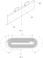
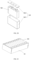
- FIG. 1 is a schematic diagram of a three-dimensional structure of an electrode assembly.
- the electrode assembly includes a negative electrode plate, a positive electrode plate, and a separator.
- the negative electrode plate, the positive electrode plate, and the separator are stacked and wound around a winding axis K to form a winding structure.
- the separator is an insulation film and used to isolate the negative electrode plate from the positive electrode plate to prevent short circuit of the negative electrode plate and the positive electrode plate.
- the winding structure of the electrode assembly is of a flat shape.
- a schematic structural diagram of a cross section of the electrode assembly in a direction perpendicular to the winding axis K may be shown in FIG. 2 .
- the electrode assembly includes a flat region 100 and bend regions 200 located at two ends of the flat region 100.
- the flat region 100 is a region with a parallel structure in the winding structure, that is, the negative electrode plate 101, the positive electrode plate 102, and the separator 103 in the flat region 100 are substantially parallel to each other. In other words, surfaces of the negative electrode plate 101, the positive electrode plate 102, and the separator 103 in the flat region 100 of the electrode assembly are all flat.
- the bend region 200 is a region with a bending structure in the winding structure, that is, the negative electrode plate 101, the positive electrode plate 102, and the separator 103 in the bend region 200 are all bent.
- the bend region 200 has a bending direction L, and the bending direction L can be understood as a direction in which surfaces of the electrode assembly in the bend region points to the flat region.
- the bending direction L is a winding direction of the winding structure in the bend region 200.
- a surface of the negative electrode plate 101 has a negative electrode active material layer composed of a negative electrode active material
- a surface of the positive electrode plate 102 has a positive electrode active material layer composed of a positive electrode active material.
- the positive electrode active material may be lithium manganate oxide, lithium cobalt oxide, lithium iron phosphate, or lithium nickel cobalt manganate
- the negative electrode active material may be graphite or silicon.
- lithium ions are deintercalated from the positive electrode and intercalated into the negative electrode.
- some exceptions may occur, for example, insufficient space for lithium intercalation in the negative electrode, excessively large resistance for intercalation of lithium ions into the negative electrode, excessively rapid deintercalation of lithium ions from the positive electrode, inability of intercalating deintercalated lithium ions into the negative electrode active material layer of the negative electrode plate in the same amount, or lithium ions that cannot be intercalated into the negative electrode plate obtaining electrons only on the surface of the negative electrode. Consequently, a silver-white metallic lithium element is formed, which is referred to as lithium precipitation.
- Lithium precipitation not only reduces performance of lithium-ion batteries and greatly shortens the cycle life, but also limits a fast charging capacity of the lithium-ion batteries.
- resulting lithium metal is so active to react with the electrolyte at a lower temperature, causing a lower self-heating start temperature (Tonset) and a higher self-heating rate, and therefore severely affecting battery safety.
- deintercalated lithium ions may form lithium crystals on the surface of the negative electrode plate, and the lithium crystals are prone to pierce the separator, to cause a risk of short circuit to the positive electrode plate and the negative electrode plate that are adjacent to each other.
- the inventor found that lithium precipitation often occurs in the bend region of the electrode assembly.
- lithium precipitation is attributed to falling-off of the active material.
- the positive active material is applied on the surface of the positive electrode plate, and the negative active material is applied on the surface of the negative electrode plate; however, the positive electrode plate and the negative electrode plate that are located in the bend region need to be bent, and therefore the active materials may fall off, which is referred to as powder falling-off. This especially occurs on an innermost-layer electrode plate in the bend region due to a largest bending degree of the innermost-layer electrode plate that easily causes falling-off of the active material.
- lithium intercalation positions on the negative electrode active material layer of the negative electrode plate may be less than lithium ions that can be provided by the positive electrode active material layer of the positive electrode plate adjacent to the negative electrode plate. As a result, the lithium battery is prone to lithium precipitation during charging.
- the electrode assembly includes a negative electrode plate, a positive electrode plate, and a separator.
- the negative electrode plate, the positive electrode plate, and the separator may be stacked and wound in a winding axis to form a winding structure, for example, a flat-shaped winding structure.
- the negative electrode plate, the positive electrode plate, and the separator may be continuously folded in a zigzag manner after being stacked.
- the electrode assembly includes a flat region and bend regions connecting two ends of the flat region.
- a barrier layer is provided between any positive electrode plate and negative electrode plate that are adjacent to each other in the bend region.
- the barrier layer is especially provided between the positive electrode plate and negative electrode plate that are adjacent to each other on an innermost side of the bend region.
- the barrier layer is used to block at least part of lithium ions deintercalated from the positive electrode active material layer of the positive electrode plate in the bend region, so that the ions blocked by the barrier layer cannot be intercalated into the negative electrode active material layer of the negative electrode adjacent to the positive electrode plate in the bend region.
- a quantity of lithium intercalation positions on the negative electrode active material layer of the negative electrode plate in the bend region is substantially the same as a quantity of lithium ions that can be provided by the positive electrode active material layer of the positive electrode plate adjacent to the negative electrode plate, thereby reducing or avoiding lithium precipitation.
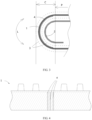
- FIG. 3 is a schematic partial structural diagram of a bend region of an electrode assembly.
- the electrode assembly includes a positive electrode plate 1, a negative electrode plate 2, and a separator 3 for isolating the positive electrode plate 1 and the negative electrode plate 2.
- the separator 3 may be independently provided between the positive electrode plate 1 and the negative electrode plate 2 that are adjacent to each other, or may be applied to a surface of the positive electrode plate 1 or the negative electrode plate 2.
- the separator 3 features electronic insulation and is used to isolate the positive electrode plate 1 and the negative electrode plate 2 that are adjacent to each other, so as to prevent a short circuit of the positive electrode plate 1 and the negative electrode plate 2 that are adjacent to each other.
- the separator 3 is provided with a large number of through micropores to ensure free passage of electrolyte ions and good permeability of lithium ions. Therefore, the separator 3 basically cannot block passage of the lithium ions.
- the separator 3 includes a separator substrate and a functional layer located on a surface of the separator substrate.
- the separator substrate may be at least one of polypropylene, polyethylene, ethylene-propylene copolymer, polybutylene terephthalate, and the like.
- the functional layer may be a mixture layer of ceramic oxide and a binder.
- the bend region C is further provided with a barrier layer 4; and at least part of the barrier layer 4 is located between the positive electrode plate 1 and the negative electrode plate 2 that are adjacent to each other, and is used to prevent at least part of ions deintercalated from the positive electrode plate 1 from being intercalated into the negative electrode plate 2 in the bend region C.
- the barrier layer 4 is provided between the positive electrode plate 1 and the negative electrode plate 2 that are adjacent to each other, so that the barrier layer 4 blocks at least part of ions deintercalated from a positive electrode active material layer (for example, a positive electrode active material layer in the bend region C) of the positive electrode plate 1 during charging, and the ions blocked by the barrier layer 4 cannot be intercalated into a negative electrode active material layer of the negative electrode plate 2 in the bend region C. In this way, when the negative electrode active material layer of the negative electrode plate 2 falls off, lithium precipitation is reduced.
- a positive electrode active material layer for example, a positive electrode active material layer in the bend region C
- the barrier layer 4 blocks at least part of the lithium ions deintercalated from the positive electrode plate 1 adjacent to the negative electrode plate 2.
- the barrier layer 4 may be made of inorganic oxide and/or macromolecular polymer.
- the inorganic oxide may be at least one of magnesium oxide (MgO), calcium oxide (CaO), boehmite, wollastonite, barium sulfate (BaSO4), calcium sulfate (CaSO4), calcium carbonate (CaCO3), aluminum oxide (Al2O3), and silicon dioxide (SiO2).
- MgO magnesium oxide
- CaO calcium oxide
- BaSO4 barium sulfate
- CaSO4 calcium sulfate
- CaCO3 calcium carbonate
- Al2O3 aluminum oxide
- SiO2 silicon dioxide
- the macromolecular polymer may be polypropylene (polypropylene), polyvinyl chloride (Polyvinyl chloride, PVC), polyethylene (polyethylene, PE), epoxy resin, polyacrylate, and polyurethane rubber.
- the barrier layer 4 may be adhesive tape or adhesive paper.
- the adhesive tape includes an adhesive and a substrate.
- the substrate may be made of polyethylene and/or ethylene-vinyl acetate copolymer (Ethylene Vinyl Acetate Copolymer, EVA), or the like.
- the adhesive paper is made of at least one of polyethylene phthalate, polyvinylidene fluoride, polyurethane, sodium polyacrylate, styrene butadiene rubber, polyetherimide, carboxymethyl cellulose, and acrylate.
- One positive electrode plate 1 and one negative electrode plate 2 may be stacked and then wound or folded, or at least one (for example, two or more) positive electrode plate 1 and at least one (for example, two or more) negative electrode plate 2 are stacked and then wound or folded, to form a bend region C.
- the bend region C includes a structure in which positive electrode plates 1 and negative electrode plates 2 are alternately arranged, and the barrier layer 4 is included between at least one positive electrode plate 1 and at least one negative electrode plate 2 that are adjacent to each other.
- the positive electrode plate 1 and the negative electrode plate 2 that are adjacent to each other in the bend region C indicate that one positive electrode plate 1 and one negative electrode plate 2 are adjacent in the bend region C, without another one positive electrode plate 1 or another one negative electrode plate 2 included in between.
- the bend region C (for example, the innermost and/or outermost side of the bend region C) may alternatively have a structure in which no negative electrode plate 2 is sandwiched between two adjacent positive electrode plates 1, or a structure in which no positive electrode plate 1 is sandwiched between two adjacent negative electrode plates 2.
- no barrier layer 4 may be provided between two positive electrode plates 1 or two adjacent negative electrode plates 2, that is, the barrier layer 4 is provided between the positive electrode plate 1 and the negative electrode plate 2 that are adjacent to each other.
- the innermost electrode plate in the bend region C of the electrode assembly is generally most bent, that is, the active material of the innermost electrode plate has a largest probability of falling-off or the active material falls off most severely.
- the innermost electrode plate may be a positive electrode plate 1 or a negative electrode plate 2.
- the barrier layer 4 is disposed between the positive electrode plate 1 and the negative electrode plate 2 that are adjacent to each other on at least the innermost side of the bend region C. In this way, lithium precipitation between the positive electrode plate and the negative electrode plate that are adjacent to each other on the innermost side can be reduced, improving safety performance.
- utilization efficiency of the active material of the positive electrode plate 1 can be improved.
- the barrier layer 4 is located between the positive electrode plate 1 and the negative electrode plate 2 that are adjacent to each other.
- the barrier layer 4 may be independently located between the positive electrode plate 1 and the negative electrode plate 2 that are adjacent to each other, or the barrier layer 4 may be attached to any surface of the positive electrode plate 1, the negative electrode plate 2, or the separator 3. That the barrier layer 4 may be independently located between the positive electrode plate 1 and the negative electrode plate 2 that are adjacent to each other means that the barrier layer 4 is stacked with each of the positive electrode plate 1 and the negative electrode plate 2 in a separated manner, not being in an adhering or coating relationship. This facilitates installation of the barrier layer 4. Attaching means adhering, applying, or spraying. By means of attaching, positional movement of the barrier layer 4 can be reduced during use of the battery cell.
- the barrier layer 4 is attached to one or two surfaces of the positive electrode plate 1, and/or the barrier layer 4 is attached to one or two surfaces of the negative electrode plate 2.
- the barrier layer 4 is independently located between the positive electrode plate 1 and the separator 3 that are adjacent to each other in the bend region C, or the barrier layer 4 is independently located between the negative electrode plate 2 and the separator 3 that are adjacent to each other in the bend region C, or the barrier layer 4 is attached to one or two surfaces of the separator 3. That the barrier layer 4 is independently located between the positive electrode plate 1 and the separator 3 that are adjacent to each other in the bend region C, or the barrier layer 4 is independently located between the negative electrode plate 2 and the separator 3 that are adjacent to each other in the bend region C indicates that the barrier layer 4 is separately stacked with the positive electrode plate 1, the negative electrode plate 2, and the separator 3, not being in an adhering or coating relationship.
- the electrode assembly further includes a flat region P connected to the bend region C.
- the bending direction L is a direction along a curved surface of the bend region C and pointing to the flat region P, and a direction perpendicular to the bending direction L is a direction vertical with the bending direction L.
- one end, extending in the bending direction L, of the barrier layer 4 is located in the flat region P, and the other end is located in the bend region C.
- the barrier layer 4 in order to block as many lithium ions as possible, has a large area as possible in the bend region C.
- two ends, extending in the bending direction L, of the barrier layer 4 are both located in the flat region P, that is, the barrier layer 4 is not only located in the bend region C but also extends to the flat region P.
- two ends, extending in the bending direction L, of the barrier layer 4 are both located at a junction between the bend region C and the flat region P, or two ends, extending in the bending direction L, of the barrier layer 4 are both close to a junction between the bend region C and the flat region P.
- the barrier layer 4 prevents, as many as possible, lithium ions deintercalated from the positive electrode plate 1 from being intercalated into the largest-curvature portion of the negative electrode plate 2, that is, the barrier layer 4 is provided opposite to the largest-curvature portion of the negative electrode plate 2, so as to cover the largest-curvature portion of the negative electrode plate 2. In this way, no lithium ions may be intercalated into the largest-curvature portion of the negative electrode plate 2 or only a small number of lithium ions are intercalated into the largest-curvature portion of the negative electrode plate 2, thereby reducing lithium precipitation.
- the largest-curvature portion of the negative electrode plate 2 on the innermost side of the bend region C is a line (for example, the line may be a straight line) perpendicular to the bending direction L on a curved surface of the negative electrode plate 2 on the innermost side of the bend region C.
- a curvature of any point on the line is greater than a curvature of a curved surface, on both sides extending from the point in the bending direction L, of the negative electrode plate 2 on the innermost side of the bend region C.
- the largest-curvature portion of the negative electrode plate 2 on the innermost side of the bend region C is a middle portion of the negative electrode plate 2 in the bend region C.
- a larger area of the barrier layer 4 in the bend region C indicates more lithium ions that can be blocked. However, more lithium ions blocked indicates lower energy density of the bend region C, resulting in lower energy density of the electrode assembly. Therefore, in another embodiment of this application, for the positive electrode plate 1 and the negative electrode plate 2 that are adjacent to each other in the bend region C, an appropriate amount of lithium ions can be deintercalated from the positive electrode plate 1 and intercalated into the negative electrode plate 2, ensuring energy density to some extent.
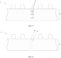
- FIG. 4 is a schematic structural diagram of distribution of barrier layers after a bend region of an electrode assembly is flattened.
- a plurality of discontinuous barrier layers 4 are included between the positive electrode plate 1 and the negative electrode plate 2 that are adjacent to each other in the bend region C.
- the plurality of discontinuous barrier layers are spaced apart in the bending direction L, so that part of lithium ions are not blocked by the barrier layer 4, that is, the part of lithium ions pass between two adjacent barrier layers 4 and are intercalated into the negative electrode active material layer of the negative electrode plate 2.
- the plurality of discontinuous barrier layers 4 are attached to the surface of the positive electrode plate 1. In this way, passage of some lithium ions can be blocked, reducing lithium precipitation and also ensuring energy density of the electrode assembly.
- FIG. 5 is a schematic structural diagram of another type of distribution of barrier layers after a bend region of an electrode assembly is flattened.
- a plurality of discontinuous barrier layers 4 are included between the positive electrode plate 1 and the negative electrode plate 2 that are adjacent to each other in the bend region.
- the plurality of discontinuous barrier layers 4 are spaced apart in a direction K perpendicular to the bending direction L, so that part of lithium ions are not blocked by the barrier layer 4, that is, the part of lithium ions pass between two adjacent barrier layers 4 and are intercalated into the negative electrode active material layer of the negative electrode plate 2.
- the plurality of discontinuous barrier layers 4 are attached to the surface of the positive electrode plate 1.
- the direction K perpendicular to the bending direction L may be a width direction of the positive electrode plate 1 and the negative electrode plate 2.
- the direction K perpendicular to the bending direction L is a winding axis direction of the winding structure.
- FIG. 6 is a schematic structural diagram of another type of distribution of barrier layers after a bend region of an electrode assembly is flattened.
- the barrier layer 4 is attached to the surface of the positive electrode plate 1.
- the barrier layer 4 is provided with at least one through hole 41, configured to allow part of lithium ions to pass through and be intercalated into the negative electrode active material layer of the negative electrode plate 2.
- the porosity of the barrier layer 4 is less than the porosity of the separator 3, so that the barrier layer 4 can more effectively block passage of lithium ions.
- the porosity is a percentage of a pore volume of bulk material in a total volume of the material in a natural state.
- a test method for porosity is a test method for true density.
- the thickness of the barrier layer 4 is A micron
- the porosity of the barrier layer 4 is B, where A and B satisfy the following relationship: 3.5 microns ⁇ A/B ⁇ 2000 microns, optionally, 7 microns ⁇ A/B ⁇ 1000 microns.
- a being excessively small indicates that the thickness of the barrier layer 4 is excessively small, and lithium crystals are prone to pierce the barrier layer 4 or even pierce the separator 3, so that the barrier layer 4 is unable to block lithium ions, possibly leading to a safety risk.
- A/B being excessively large indicates that the porosity of the barrier layer 4 is excessively large.
- a larger porosity of the barrier layer 4 indicates more lithium ions that pass through the protective layer 4, possibly resulting in severe lithium precipitation.
- A/B being less than 3.5 indicates that A is relatively small, that is, the thickness of the barrier layer 4 is excessively small and B is relatively large. In other words, the porosity of the barrier layer 4 is excessively large, and the barrier layer 4 loses the function of blocking lithium ions, possibly leading to a safety risk.
- A/B being greater than 2000 indicates that A is relatively large, that is, the thickness of the barrier layer 4 is excessively large and B is relatively small. In other words, the porosity of the barrier layer 4 is excessively small, which severely affects energy density of the battery cell.
- the thickness of the barrier layer 4 is 2 to 200 microns (um); optionally, the thickness of the barrier layer 4 is 5 to 100 microns; further optionally, the thickness of the barrier layer 4 is 5 to 50 microns.
- the thickness of the barrier layer 4 being less than 2 um indicates that the thickness of the barrier layer 4 is excessively small. In case of severe lithium precipitation, lithium crystals pierce the barrier layer 4 and even pierce the separator 3, and consequently the barrier layer 4 is unable to block lithium ions, leading to a safety risk.
- the thickness of the barrier layer 4 being greater than 500 um indicates that the thickness of the barrier layer 4 is excessively large, leading to an excessively large gap between the positive electrode plate 1 and the negative electrode plate 2 that are adjacent to each other.
- the barrier layer 4 occupies space, which may affect the energy density of the electrode assembly. In addition, an excessively large gap between two adjacent layers may severely affect cycle performance.
- the porosity of the barrier layer 4 is 10% to 70%; optionally, the porosity of the barrier layer 4 is 20% to 60%. This can ensure both safety of the electrode assembly and energy density of the electrode assembly, achieving a better balance between safety performance and energy density. For example, when the porosity is less than 10%, most or all of the lithium ions may be blocked by the barrier layer 4, and cannot be intercalated into the negative electrode plate 2, thereby affecting the energy density of the electrode assembly. However, when the porosity is greater than 70%, most or almost all of the lithium ions may pass through the barrier layer 4, leading to a risk of lithium precipitation. As a result, lithium crystals may pierce the barrier layer 4, and the barrier layer 4 is unable to block lithium ions, leading to a safety risk.
- the width direction of the positive electrode plate 1 and the negative electrode plate 2 is parallel to the winding axis direction, and the width direction of the positive electrode plate 1 and the negative electrode plate 2 is perpendicular to the bending direction L.
- the width direction of the positive electrode plate 1 and the negative electrode plate 2 is parallel to the direction perpendicular to the bending direction L.
- the width direction of the positive electrode plate 1 and the negative electrode plate 2 is collectively referred to as the direction K.
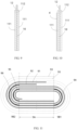
- FIG. 7 is a schematic structural diagram of a negative electrode plate .
- the negative electrode plate 2 includes a negative electrode body portion 21 and a negative electrode tab 22 extending outwards the negative electrode body portion 21 in the direction K. At least a partial region on a surface of the negative electrode body portion 21 in the direction K is a negative electrode active material region 211.
- the negative electrode active material region 211 is used to coat the negative active material, and the negative electrode active material may be graphite or silicon.
- the negative electrode active material region 211 is not only provided in the partial region on the surface of the negative electrode body portion 21; the negative electrode active material region 211 is also provided on a surface of the negative electrode tab 22 and a root region near the negative electrode body portion 21, that is, a partial region of the negative electrode tab 22 is the negative electrode active material region 211.
- the negative electrode active material region 211 covers the entire surface of the negative electrode body portion 21 in the direction K.
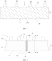
- FIG. 8 is a schematic structural diagram of a positive electrode plate.
- the positive electrode plate 1 includes a positive electrode body portion 11 and at least one positive electrode tab portion 12 extending outwards the positive electrode body portion 11 in the direction K. At least a partial region of the surface of the positive electrode body portion 11 is a positive electrode active material region 111.
- the positive electrode active material region 111 may be coated with a positive electrode active material, for example, the positive electrode active material may be a ternary material, lithium manganate oxide, or lithium iron phosphate.
- the surface of the positive electrode body portion 11 further includes a first insulation layer coated region 112 adjacent to the positive electrode active material region 111, and the first insulation layer coated region 112 is located at a side of the positive electrode active material region 111 adjacent to the positive electrode tab portion 12.
- the first insulation layer coated region 112 is used for coating with an insulation material, to insulate and isolate the positive active material region 111 from the positive electrode tab portion 12.
- FIG. 9 is a schematic structural diagram of a cross section in a direction A-A in FIG. 8 .
- the positive electrode active material region 111 is provided on two surfaces of a current collector 10 of the positive electrode plate 1, and the positive electrode tab portion 12 is a part of the current collector 10 of the positive electrode plate 1.
- the current collector 10 may be made of aluminum.
- the positive electrode active material region 111 and the first insulation layer coated region 112 are distributed at two ends, in the width direction (the direction K) of the positive electrode body portion 11, of the surface of the positive electrode body portion 11, and the positive electrode tab portion 12 and the first insulation layer coated region 112 belongs to the same end of the positive electrode body portion 11.
- the positive electrode active material region 111 and the first insulation layer coated region 112 are two substantially parallel regions on the surface of the positive electrode body portion 11, and are distributed as two layers on the surface of the positive electrode body portion 11 in the direction K.
- the first insulation layer coated region 112 may be located at a joint portion between the positive electrode body portion 11 and the positive electrode tab portion 12.
- the first insulation layer coated region 112 is located on the surface of the positive electrode body portion 11 and the joint portion between the positive electrode body portion 11 and the positive electrode tab portion 12, and is used to isolate the surface of the positive electrode tab portion 12 from the positive electrode active material region 111.
- the first insulation layer coated region 112 is provided on the surface of the positive electrode body portion 11, and a second insulation layer coated region 121 is also provided in the root region of the positive electrode tab portion 12 close to the positive electrode body portion 11.
- the second insulation layer coated region 121 are used for coating of an insulation material.
- An insulation material is applied to the surface of the first insulation layer coated region 112, and the insulation material includes an inorganic filler and a binder.
- the inorganic filler includes one or more of boehmite, aluminum oxide, magnesium oxide, titanium dioxide, zirconium oxide, silicon dioxide, silicon carbide, boron carbide, calcium carbonate, aluminum silicate, calcium silicate, potassium titanate, and barium sulfate.
- the binder includes one or more of polyvinylidene fluoride, polyacrylonitrile, polyacrylic acid, polyacrylate, polyacrylic acid-acrylate, polyacrylonitrile-acrylic acid, and polyacrylonitrile-acrylate.
- Each positive electrode plate 1 may include one, two, or more than two positive electrode tab portions 12. When the positive electrode plate 1 includes two or more positive tab portions 12, all the positive pole tab portions 12 are located on the same side of the positive electrode plate 1 in the direction K.
- two ends of the negative electrode active material region 211 of the negative electrode plate 2 in the direction K extend beyond corresponding ends of the positive electrode active material region 111 of the adjacent positive electrode plate 1. This can ensure the energy density of the electrode assembly.
- the two ends of the negative electrode active material region 211 in the direction K are a first end 23 and a second end 24, and the two ends of the positive electrode active material region 111 in the direction K are a third end 13 and a fourth end 14.
- the first end 23 of the negative electrode active material region 211 and the third end 13 of the positive electrode active material region 111 are located on the same side of the electrode assembly in the direction K, and the first end 23 of the negative electrode active material region 211 extends beyond the third end 13 of the positive electrode active material region 111 in the direction K.
- the second end 24 of the negative electrode active material region 211 and the fourth end 14 of the positive electrode active material region 111 are located on the other side of the electrode assembly in the direction K, and the second end 24 of the negative electrode active material region 211 extends beyond the fourth end 14 of the positive electrode active material region 111 in the direction K.
- a size by which the two ends of the negative electrode active material region 211 extending beyond the corresponding ends of the positive electrode active material region 111 along the winding axis K may be the same or different.
- an exceeding size ranges from 0.2 mm to 5 mm.
- FIG. 10 is a schematic structural diagram of a cross section in a direction B-B in FIG. 8 .
- the barrier layer 4 is attached to the surface of the positive electrode active material region 111, that is, the surface of the positive electrode active material layer.
- the barrier layer 4 includes a fifth end 42 and a sixth end 43 in the direction perpendicular to the bending direction (which is the direction K), and the fifth end 42 of the barrier layer 4 extends beyond the positive electrode active material layer of the positive electrode plate 1, and/or the sixth end 43 of the barrier layer 4 exceeds beyond the positive electrode active material layer.
- the fifth end 42 of the barrier layer 4 exceeds the third end 13 of the positive electrode active material region 111 in the direction K
- the sixth end 43 of the barrier layer 4 extends beyond the fourth end 14 of the positive electrode active material region 111 in the direction K, for example, the exceeding size ranges from 0.2 mm to 5 mm. In this way, passage of more lithium ions can be blocked, reducing lithium precipitation.
- Both the fifth end 42 and the sixth end 43 of the barrier layer 4 do not exceed the corresponding ends of the negative electrode active material layer of the negative electrode plate 2. That is, the first end 23 of the negative electrode active material region of the negative electrode plate 2 extends beyond the fifth end 42 of the barrier layer 4, and/or the second end 24 of the negative electrode active material region of the negative electrode plate 2 extends beyond the sixth end 43 of the barrier layer 4. In this way, lithium ions can be intercalated into a portion of the negative electrode plate 2 extending beyond the barrier layer 4, ensuring the energy density of the electrode assembly.
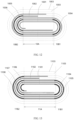
- FIG. 11 is a schematic structural diagram of a cross section perpendicular to a winding axis of a flat-shaped electrode assembly.
- the electrode assembly includes a negative electrode plate 91, a positive electrode plate 92, a separator 93, a first barrier layer 94, a second barrier layer 95, and a third barrier layer 96.
- the separator 93 is located between the negative electrode plate 91 and the positive electrode plate 92, and there are two separators 93, indicated by two winding dashed lines in the cross-sectional view of the electrode assembly in FIG. 11 .
- the negative electrode plate 91, the positive electrode plate 92, and the separator 93 are stacked and then wound into a flat-shaped winding structure around the winding axis.
- the winding structure of the electrode assembly includes a flat region 9A, and a first bend region 9B1 and a second bend region 9B2 that are located on two sides of the flat region 9A. Division of the flat region 9A from the first bend region 9B1 and the second bend region 9B2 is separately denoted by a straight dotted line.
- the negative electrode plate 91 and the positive electrode plate 92 included in the first bend region 9B1 and the second bend region 9B2 of the electrode assembly are alternately stacked in sequence.
- the separator 93 is provided between the negative electrode plate 91 and the positive electrode plate 92 that are adjacent to each other.
- Innermost electrode plates in the first bend region 9B1 and the second bend region 9B2 are both the negative electrode plate 91.
- a barrier layer is provided (attached to) on inner surfaces of at least innermost positive electrode plates 92 in the first bend region 9B1 and the second bend region 9B2.
- a barrier layer is provided (attached to) on an inner surface of each layer of positive electrode plate 92 in the first bend region 9B1 and the second bend region 9B2.
- the inner surface of the positive electrode plate 92 is a surface of the positive electrode plate 92 facing toward the winding axis, or a surface facing toward inside of the winding structure.
- the first bend region 9B1 has a plurality of layers of electrode plates, such as three layers of electrode plates.
- An innermost-layer electrode plate (also referred to as the first layer) and an outermost-layer electrode plate (also referred to as the third layer) of the first bend region 9B1 are both the negative electrode plate 91, and an electrode plate (also referred to as the second-layer electrode plate) between the innermost-layer electrode plate and the outermost-layer electrode plate is the positive electrode plate 92.
- the positive electrode plate 92 is a positive electrode plate on the innermost side of the first bend region 9B 1, and the first barrier layer 94 is attached to an inner surface of the positive electrode plate 92 in the first bend region 9B 1.
- the second bend region 9B2 has a plurality of layers of electrode plates, such as five layers of electrode plates. In a direction from inside to outside of the winding structure, the negative electrode plate 91 and the positive electrode plate 92 in the second bend region 9B2 are alternately stacked in sequence. An innermost-layer electrode plate in the second bend region 9B2 is the negative electrode plate 91, and a barrier layer is attached to an inner surface of each layer of positive electrode plate 92 in the second bend region 9B2.
- the second bend region 9B2 sequentially includes the first-layer, second-layer, third-layer, fourth-layer, and fifth-layer electrode plates.
- the first-layer, third-layer, and fifth-layer electrode plates are the negative electrode plate 91; and the second-layer and fourth-layer electrode plates are the positive electrode plate 92.
- a barrier layer is attached to the inner surface of each layer of layer of positive electrode plate 92 in the second bend region 9B2.
- the second barrier layer 95 is attached to an inner surface of the second-layer electrode plate (which is the positive electrode plate 92) in the second bend region 9B2.
- the third barrier layer 96 is attached to an inner surface of the fourth-layer electrode plate (which is the positive electrode plate 92) in the second bend region 9B2.
- Two ends of each of the first barrier layer 94, the second barrier layer 95, and the third barrier layer 96 in the bending direction are located at the junctions between the bend region and the flat region.
- two ends of the first barrier layer 94 in the winding direction are separately located at the junction between the first bend region 9B1 and the flat region 9A
- two ends of each of the second barrier layer 95 and the third barrier layer 96 in the winding direction are separately located at the junction between the second bend region 9B2 and the flat region 9A.
- first barrier layer 94 For related content of functions, structures, and distribution of the first barrier layer 94, the second barrier layer 95, and the third barrier layer 96, refer to related content of the barrier layer described in the embodiments of FIGs. 1 to 10 . Details are not repeated herein.
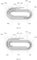
- FIG. 12 is a schematic structural diagram of a cross section perpendicular to a winding axis of another flat-shaped electrode assembly.
- the electrode assembly includes a negative electrode plate 1001, a positive electrode plate 1002, a separator 1003, a first barrier layer 1004, a second barrier layer 1005, and a third barrier layer 1006.
- the separator 1003 is located between the negative electrode plate 1001 and the positive electrode plate 1002.
- the negative electrode plate 1001, the positive electrode plate 1002, and the separator 1003 are stacked and then wound into a flat-shaped winding structure around the winding axis.
- the winding structure of the electrode assembly includes a flat region 10A, and a first bend region 10B1 and a second bend region 10B2 that are located on two sides of the flat region 10A.
- the electrode assembly is basically similar to the electrode assembly described in the example corresponding to FIG. 11 , and the difference may be as follows:
- a barrier layer is provided (attached to) on outer surfaces of at least innermost positive electrode plates 1002 in the first bend region 10B1 and the second bend region 10B2.
- a barrier layer is provided (attached to) on an outer surface of each layer of positive electrode plate 1002 in the first bend region 10B1 and the second bend region 10B2.
- the outer surface of the positive electrode plate 1002 is a surface of the positive electrode plate 1002 facing away from the winding axis, or a surface facing away from inside of the winding structure.
- the first barrier layer 1004 is attached to an outer surface of the positive electrode plate 1002 in the first bend region 10B1.
- the second barrier layer 1005 is attached to an outer surface of the second-layer electrode plate (which is the positive electrode plate 1002) in the second bend region 10B2.
- a third barrier layer 1006 is attached to an outer surface of the fourth-layer electrode plate (which is the positive electrode plate 1002) in the second bend region 10B2.
- Two ends of the first barrier layer 1004 in the winding direction are located at the junctions between the first bend region 10B1 and the flat region 10A, and two ends of each of the second barrier layer 1005 and the third barrier layer 1006 in the winding direction are located at the junctions between the second bend region 10B2 and the flat region 10A.
- first barrier layer 1004 the second barrier layer 1005, and the third barrier layer 1006 refer to related content of the barrier layer described in the embodiments or examples of FIGs. 1 to 10 . Details are not repeated herein.
- FIG. 13 is a schematic structural diagram of a cross section perpendicular to a winding axis of another flat-shaped electrode assembly n.
- the electrode assembly includes a negative electrode plate 1101, a positive electrode plate 1102, a separator 1103, a first barrier layer 1104, a second barrier layer 1105, a third barrier layer 1106, a fourth barrier layer 1107, and a fifth barrier layer 1108.
- the separator 1103 is located between the negative electrode plate 1101 and the positive electrode plate 1102.
- the negative electrode plate 1101, the positive electrode plate 1102, and the separator 1103 are stacked and then wound into a flat-shaped winding structure around the winding axis.
- the winding structure of the electrode assembly includes a flat region 11A, and a first bend region 11B 1 and a second bend region 11B2 that are located on two sides of the flat region 11A.
- the electrode assembly is basically similar to the electrode assembly described in the example corresponding to FIG. 11 , and the difference may be as follows:
- a barrier layer is provided (attached to) on inner surfaces of at least innermost negative electrode plates 1101 in a first bend region 11B1 and a second bend region 11B2.
- a barrier layer is provided on an inner surface of each layer of negative electrode plate 1101 in the first bend region 11B1 and the second bend region 11B2.
- the inner surface of the negative electrode plate 1101 is a surface of the negative electrode plate 1101 facing toward the winding axis, or a surface facing toward inside of the winding structure.
- first barrier layer 1104 is attached to an inner surface of an innermost-layer electrode plate (which is the negative electrode plate 1101) in the first bend region 11B1
- second barrier layer 1105 is attached to an inner surface of an outermost-layer electrode plate (which is the negative electrode plate 1101).
- the third barrier layer 1106 is attached to an inner surface of the first-layer electrode plate (which is the negative electrode plate 1101) in the second bend region 11B2.
- the fourth barrier layer 1107 is attached to an inner surface of the third-layer electrode plate (which is the negative electrode plate 1101) in the second bend region 11B2.
- the fifth barrier layer 1108 is attached to an inner surface of the fifth-layer electrode plate (which is the negative electrode plate 1101) in the second bend region 11B2.
- Two ends of each of the first barrier layer 1104 and the second barrier layer 1105 in the winding direction are located at the junctions between the first bend region 11B1 and the flat region 11A, and two ends of each of the third barrier layer 1106, the fourth barrier layer 1107, and the fifth barrier layer 1108 in the winding direction are located at the junctions between the second bend region 11B2 and the flat region 11A.
- first barrier layer 1104 For related content of functions, structures, and distribution of the first barrier layer 1104, the second barrier layer 1105, and the third barrier layer 1106, the fourth barrier layer 1107, and the fifth barrier layer 1108, refer to related content of the barrier layer described in the embodiments or examples of FIGs. 1 to 10 . Details are not repeated herein.
- FIG. 14 is a schematic structural diagram of a cross section perpendicular to a winding axis of another flat-shaped electrode assembly.
- the electrode assembly includes a negative electrode plate 1201, a positive electrode plate 1202, a separator 1203, a first barrier layer 1204, a second barrier layer 1205, a third barrier layer 1206, a fourth barrier layer 1207, and a fifth barrier layer 1208.
- the separator 1203 is located between the negative electrode plate 1201 and the positive electrode plate 1202.
- the negative electrode plate 1201, the positive electrode plate 1202, and the separator 1203 are stacked and then wound into a flat-shaped winding structure around the winding axis.
- the winding structure of the electrode assembly includes a flat region 12A, and a first bend region 12B1 and a second bend region 12B2 that are located on two sides of the flat region 12A.
- the electrode assembly is basically similar to the electrode assembly described in the example corresponding to FIG. 11 , and the difference may be as follows:
- a barrier layer is provided (attached to) on outer surfaces of at least innermost negative electrode plates 1201 in the first bend region 12B 1 and the second bend region 12B2.
- a barrier layer is provided on an outer surface of each layer of negative electrode plate 1201 in the first bend region 12B1 and the second bend region 12B2.
- the outer surface of the negative electrode plate 1201 is a surface of the negative electrode plate 1201 facing away from the winding axis, or a surface facing away from inside of the winding structure.
- first barrier layer 1204 is attached to an outer surface of an innermost-layer electrode plate (which is the negative electrode plate 1201) in the first bend region 12B1
- second barrier layer 1205 is attached to an outer surface of an outermost-layer electrode plate (which is the negative electrode plate 1201).
- the third barrier layer 1206 is attached to an outer surface of the first-layer electrode plate (which is the negative electrode plate 1201) in the second bend region 12B2.
- the fourth barrier layer 1207 is attached to an outer surface of the third-layer electrode plate (which is the negative electrode plate 1201) in the second bend region 12B2.
- the fifth barrier layer 1208 is attached to an outer surface of the fifth-layer electrode plate (which is the negative electrode plate 1201) in the second bend region 12B2.
- Two ends of each of the first barrier layer 1204 and the second barrier layer 1205 in the winding direction are located at the junctions between the first bend region 12B1 and the flat region 12A, and two ends of each of the third barrier layer 1206, the fourth barrier layer 1207, and the fifth barrier layer 1208 in the winding direction are located at the junctions between the second bend region 12B2 and the flat region 12A.
- first barrier layer 1204 For related content of functions, structures, and distribution of the first barrier layer 1204, the second barrier layer 1205, and the third barrier layer 1206, the fourth barrier layer 1207, and the fifth barrier layer 1208, refer to related content of the barrier layer described in the embodiments or examples of FIGs. 1 to 10 . Details are not repeated herein.
- FIG. 15 is a schematic structural diagram of a cross section perpendicular to a winding axis of another flat-shaped electrode assembly.
- the electrode assembly includes a negative electrode plate 1301, a positive electrode plate 1302, a separator 1303, and a plurality of barrier layers 1304.
- the separator 1303 is located between the negative electrode plate 1301 and the positive electrode plate 1302.
- the negative electrode plate 1301, the positive electrode plate 1302, and the separator 1303 are stacked and then wound into a flat-shaped winding structure around the winding axis.
- the winding structure of the electrode assembly includes a flat region 13A, and a first bend region 13B1 and a second bend region 13B2 that are located on two sides of the flat region 13A.
- the electrode assembly is basically similar to the electrode assembly described in the example corresponding to FIG. 11 , and the difference may be as follows:
- the barrier layer 1304 is provided on inner surfaces of at least innermost separators 1303 in the first bend region 13B 1 and the second bend region 13B2.
- the barrier layer 1304 is provided on an inner surface of each layer of separator 1303 in the first bend region 13B 1 and the second bend region 13B2.
- the inner surface of the separator 1303 is a surface of the separator 1303 facing toward the winding axis, or a surface facing toward inside of the winding structure.
- each barrier layer 1304 in the winding direction in the first bend region 13B1 are located at the junctions between the first bend region 13B1 and the flat region 13A, and two ends of each barrier layer 1304 in the winding direction in the second bend region 13B2 are located at the junctions between the second bend region 12B2 and the flat region 12A.
- each barrier layer 1304 For related content of functions, structures, and distribution of each barrier layer 1304, refer to related content of the barrier layer described in the embodiments or examples of FIGs. 1 to 10 . Details are not repeated herein.
- FIG. 16 is a schematic structural diagram of a cross section perpendicular to a winding axis of another flat-shaped electrode assembly.
- the electrode assembly includes a negative electrode plate 1401, a positive electrode plate 1402, a separator 1403, and a plurality of barrier layers 1404.
- the separator 1403 is located between the negative electrode plate 1401 and the positive electrode plate 1402.
- the negative electrode plate 1401, the positive electrode plate 1402, and the separator 1403 are stacked and then wound into a flat-shaped winding structure around the winding axis.
- the winding structure of the electrode assembly includes a flat region 14A, and a first bend region 14B1 and a second bend region 14B2 that are located on two sides of the flat region 14A.
- the electrode assembly is basically similar to the electrode assembly described in the example corresponding to FIG. 11 , and the difference may be as follows:
- the barrier layer 1404 is provided on outer surfaces of at least innermost separators 1403 in the first bend region 14B 1 and the second bend region 14B2.
- the barrier layer 1404 is provided on an outer surface of each layer of separator 1403 in the first bend region 14B1 and the second bend region 14B2.
- the outer surface of the separator 1403 is a surface of the separator 1403 facing away from the winding axis, or a surface facing away from inside of the winding structure.
- each barrier layer 1404 in the winding direction in the first bend region 14B1 are located at the junctions between the first bend region 14B1 and the flat region 14A, and two ends of each barrier layer 1404 in the winding direction in the second bend region 14B2 are located at the junctions between the second bend region 12B2 and the flat region 12A.
- each barrier layer 1404 For related content of functions, structures, and distribution of each barrier layer 1404, refer to related content of the barrier layer described in the embodiments or examples of FIGs. 1 to 10 . Details are not repeated herein.
- FIG. 17 is a schematic structural diagram of a cross section perpendicular to a winding axis of another flat-shaped electrode assembly.
- the electrode assembly includes a negative electrode plate 1501, a positive electrode plate 1502, a separator 1503, and a plurality of barrier layers 1504.
- the separator 1503 is located between the negative electrode plate 1501 and the positive electrode plate 1502.
- the negative electrode plate 1501, the positive electrode plate 1502, and the separator 1503 are stacked and then wound into a flat-shaped winding structure around the winding axis.
- the winding structure of the electrode assembly includes a flat region 15A, and a first bend region 15B1 and a second bend region 15B2 that are located on two sides of the flat region 15A.
- the negative electrode plate 1501 and the positive electrode plate 1502 that are included in the first bend region 15B1 and the second bend region 15B2 of the electrode assembly are alternately stacked in sequence, and the separator 1503 is provided between any negative electrode plate 1501 and positive electrode plate 1502 that are adjacent to each other in the first bend region 15B1 and the second bend region 15B2.
- Innermost electrode plates in the first bend region 15B1 and the second bend region 15B2 are all negative electrode plates 1501.
- the barrier layer 1504 is provided on both inner and outer surfaces of at least the innermost positive electrode plates 1502 in the first bend region 15B1 and the second bend region 15B2, for example, the barrier layer 1504 is provided on both inner and outer surfaces of each layer of positive electrode plate 1502 in the first bend region 15B1 and the second bend region 15B2.
- the inner surface of the positive electrode plate 1502 is a surface of the positive electrode plate 1502 facing toward the winding axis, or a surface facing toward inside of the winding structure.
- the outer surface of the positive electrode plate 1502 is a surface of the positive electrode plate 1502 facing away from the winding axis, or a surface facing away from inside of the winding structure.
- the first bend region 15B1 has a plurality of layers of electrode plates, such as three layers of electrode plates.
- the innermost-layer (also referred to as first-layer) electrode plate and the outermost-layer (also referred to as third-layer) electrode plate in the first bend region 15B1 are both the negative electrode plate 1501.
- An electrode plate (also referred to as the second-layer electrode plate) between the innermost-layer electrode plate and the outermost-layer electrode plate in the first bend region 15B 1 is the positive electrode plate 1502.
- the barrier layer 1504 is provided (attached to) on both an inner surface and an outer surface of the positive electrode plate 1502 in the first bend region 15B 1.
- the second bend region 15B2 has a plurality of layers of electrode plates, such as five layers of electrode plates. In a direction from inside to outside of the winding structure, the negative electrode plate 1501 and the positive electrode plate 1502 in the second bend region 15B2 are alternately stacked in sequence. An innermost-layer electrode plate in the second bend region 15B2 is the negative electrode plate 1501, and the barrier layer 1504 is provided (attached to) on both an inner surface and an outer surface of each layer of positive electrode plate 1502 in the second bend region 15B2.
- the second bend region 15B2 sequentially includes the first-layer, second-layer, third-layer, fourth-layer, and fifth-layer electrode plates.
- the first-layer, third-layer, and fifth-layer electrode plates are the negative electrode plate 1501; and the second-layer and fourth-layer electrode plates are the positive electrode plate 1502.
- the barrier layer 1504 is provided on both inner surfaces and outer surfaces of the second-layer and fourth-layer electrode plates in the second bend region 15B2.
- each barrier layer 1504 in the bending direction (that is, in the winding direction) are located at the junctions between the bend region and the flat region.
- two ends of each barrier layer 1504 in the first bend region 15B1 in the winding direction are located at the junctions between the first bend region 15B1 and the flat region 15A
- two ends of each barrier layer 1504 in the second bend region 15B2 in the winding direction are located at the junctions between the second bend region 15B2 and the flat region 15A.
- each barrier layer 1504 For related content of functions, structures, and distribution of each barrier layer 1504, refer to related content of the barrier layer described in the embodiments or examples of FIGs. 1 to 10 . Details are not repeated herein.
- FIG. 18 is a schematic structural diagram of a cross section perpendicular to a winding axis of a flat-shaped electrode assembly.
- the electrode assembly includes a negative electrode plate 1601, a positive electrode plate 1602, a separator 1603, a first barrier layer 1604, a second barrier layer 1605, and a third barrier layer 1606.
- the separator 1603 is located between the negative electrode plate 1601 and the positive electrode plate 1602.
- the negative electrode plate 1601, the positive electrode plate 1602 and the separator 1603 are stacked and then wound into a flat-shaped winding structure around the winding axis.
- the winding structure of the electrode assembly includes a first flat region 16A1, a second flat region 16A2, a first bend region 16B1, and a second bend region 16B2.
- the first flat region 16A1 and the second flat region 16A2 are disposed opposite each other.
- the first bend region 16B1 and the second bend region 16B2 are disposed opposite each other.
- Two ends of the first bend region 16B1 are respectively connected to ends of the first flat region 16A1 and the second flat region 16A2 on the same side.
- Two ends of the second bend region 16B2 are respectively connected to the other ends of the first flat region 16A1 and the second flat region 16A2 on the same side.
- the negative electrode plate 1601 and the positive electrode plate 1602 included in the first bend region 16B1 and the second bend region 16B2 of the electrode assembly are alternately stacked in sequence.
- the separator 1603 is provided between the negative electrode plate 1601 and the positive electrode plate 1602 that are adjacent to each other.
- Innermost electrode plates in the first bend region 16B 1 and the second bend region 16B2 are both negative electrode plates 1601.
- a barrier layer is provided (attached to) on inner surfaces of at least innermost positive electrode plates in the first bend region 16B1 and the second bend region 16B2.
- a barrier layer is provided (attached to) on an inner surface of each layer of positive electrode plate 1602 in the first bend region 16B 1 and the second bend region 16B2.
- the inner surface of the positive electrode plate 1602 is a surface of the positive electrode plate 1602 facing toward the winding axis, or a surface facing toward inside of the winding structure.
- the first bend region 16B1 has a plurality of layers of electrode plates, such as three layers of electrode plates.
- the innermost-layer (also referred to as first-layer) electrode plate and the outermost-layer (also referred to as third-layer) electrode plate in the first bend region 16B1 are both the negative electrode plate 1601.
- An electrode plate (also referred to as the second-layer electrode plate) between the innermost-layer electrode plate and the outermost-layer electrode plate is the positive electrode plate 1602.
- the first barrier layer 1604 is attached to an inner surface of the positive electrode plate 1602 in the first bend region 16B1.
- the second bend region 16B2 has a plurality of layers of electrode plates, such as five layers of electrode plates.
- the negative electrode plate 1601 and the positive electrode plate 1602 in the second bend region 16B2 are alternately stacked in sequence.
- An innermost-layer electrode plate in the second bend region 16B2 is the negative electrode plate 1601, and a barrier layer is attached to an inner surface of each layer of positive electrode plate 1602 in the second bend region 16B2.
- the second bend region 16B2 sequentially includes the first-layer, second-layer, third-layer, fourth-layer, and fifth-layer electrode plates.
- the first-layer, third-layer, and fifth-layer electrode plates are the negative electrode plate 1601; and the second-layer and fourth-layer electrode plates are the positive electrode plate 1602.
- the second barrier layer 1605 is attached to an inner surface of the positive electrode plate 1602 in the negative electrode plate 1601 and the positive electrode plate 1602 that are adjacent to each other on the innermost side of the second bend region 16B2, that is, the second barrier layer 1605 is attached to an inner surface of the second-layer electrode plate (which is the positive electrode plate 1602) in the second bend region 16B2.
- the third barrier layer 1606 is attached to an inner surface of the fourth-layer electrode plate (which is the positive electrode plate 1602) in the second bend region 16B2.
- the first barrier layer 1604 includes a first end and a second end in the bending direction (that is, in the winding direction).
- the first end of the first barrier layer 1604 is located in the first bend region 16B1, and the second end of the layer 1604 is located in the first flat region 16A1.
- the second barrier layer 1605 includes a first end and a second end in the bending direction (that is, in the winding direction).
- the first end of the second barrier layer 1605 is located in the second bend region 16B2, and the second end of the second barrier layer 1605 is located in the second flat region 16A2.
- the third barrier layer 1606 includes a first end and a second end in the bending direction (that is, in the winding direction).
- the first end of the third barrier layer 1606 is located in the second bend region 16B2, and the second end of the third barrier layer 1606 is located in the second flat region 16A2.
- the first end of the third barrier layer 1606 is located in the second bend region 16B2, and the second end of the third barrier layer 1606 is located in the first flat region 16A1.
- first barrier layer 1604 the second barrier layer 1605, and the third barrier layer 1606, refer to related content of the barrier layer described in the embodiments or examples of FIGs. 1 to 10 . Details are not repeated herein.
- FIG. 19 is a schematic structural diagram of a cross section perpendicular to a winding axis of a flat-shaped electrode assembly.
- the electrode assembly includes a negative electrode plate 1701, a positive electrode plate 1702, a separator 1703, a first barrier layer 1704, a second barrier layer 1705, and a third barrier layer 1706.
- the separator 1703 is located between the negative electrode plate 1701 and the positive electrode plate 1702.
- the negative electrode plate 1701, the positive electrode plate 1702, and the separator 1703 are stacked and then wound into a flat-shaped winding structure around the winding axis.
- the winding structure of the electrode assembly includes a first flat region 17A1, a second flat region 17A2, a first bend region 17B1, and a second bend region 17B2.
- the first flat region 17A1 and the second flat region 17A2 are disposed opposite each other.
- the first bend region 17B1 and the second bend region 17B2 are disposed opposite each other.
- Two ends of the first bend region 17B1 are respectively connected to ends of the first flat region 17A1 and the second flat region 17A2 on the same side.
- Two ends of the second bend region 17B2 are respectively connected to the other ends of the first flat region 17A1 and the second flat region 17A2 on the same side.
- the negative electrode plate 1701 and the positive electrode plate 1702 included in the first bend region 17B1 and the second bend region 17B2 of the electrode assembly are alternately stacked in sequence.
- the separator 1703 is provided between the negative electrode plate 1701 and the positive electrode plate 1702 that are adjacent to each other.
- Innermost electrode plates in the first bend region 17B 1 and the second bend region 17B2 are both negative electrode plates 1701.
- a barrier layer is provided (attached to) on inner surfaces of at least innermost positive electrode plates 1702 in the first bend region 17B 1 and the second bend region 17B2.
- a barrier layer is provided (attached to) on an inner surface of each layer of positive electrode plate 1702 in the first bend region 17B 1 and the second bend region 17B2.
- the inner surface of the positive electrode plate 1702 is a surface of the positive electrode plate 1702 facing toward the winding axis, or a surface facing toward inside of the winding structure.
- the first bend region 17B1 has a plurality of layers of electrode plates, such as three layers of electrode plates.
- the innermost-layer (also referred to as first-layer) electrode plate and the outermost-layer (also referred to as third-layer) electrode plate in the first bend region 17B1 are both the negative electrode plate 1701.
- An electrode plate (also referred to as the second-layer electrode plate) between the innermost-layer electrode plate and the outermost-layer electrode plate is the positive electrode plate 1702.
- the first barrier layer 1704 is attached to an inner surface of the positive electrode plate 1702 in the first bend region 17B1.
- the second bend region 17B2 is provided with a plurality of layers of electrode plates, such as five layers of electrode plates. In a direction from inside to outside of the winding structure, the negative electrode plate 1701 and the positive electrode plate 1702 in the second bend region 17B2 are alternately stacked in sequence. An innermost-layer electrode plate in the second bend region 17B2 is the negative electrode plate 1701, and a barrier layer is attached to an inner surface of each layer of positive electrode plate 1702 in the second bend region 17B2.
- the second bend region 17B2 sequentially includes the first-layer, second-layer, third-layer, fourth-layer, and fifth-layer electrode plates.
- the first-layer, third-layer, and fifth-layer electrode plates are the negative electrode plate 1701; and the second-layer and fourth-layer electrode plates are the positive electrode plate 1702.
- the second barrier layer 1705 is attached to an inner surface of the positive electrode plate 1702 in the negative electrode plate 1701 and the positive electrode plate 1702 that are adjacent to each other on the innermost side of the second bend region 17B2, that is, the second barrier layer 1705 is attached to an inner surface of the second-layer electrode plate (which is the positive electrode plate 1702) in the second bend region 17B2.
- the third barrier layer 1706 is attached to an inner surface of the fourth-layer electrode plate (which is the positive electrode plate 1702) in the second bend region 17B2.
- the first barrier layer 1704 includes a first end and a second end in the bending direction (that is, in the winding direction), and the first end and the second end of the first barrier layer 1704 are both located in the first bend region 17B1.
- the second barrier layer 1705 includes a first end and a second end in the bending direction (that is, in the winding direction).
- the first end of the second barrier layer 1705 is located at a junction between the second bend region 17B2 and the first flat region 17A1
- the second end of the second barrier layer 1705 is located at a junction between the second bend region 17B2 and the second flat region 17A2.
- the third barrier layer 1706 includes a first end and a second end in the bending direction (that is, in the winding direction), and the first end and the second end of the third barrier layer 1706 are both located in the second bend region 17B2.
- curvatures of the layers of electrode plates decrease sequentially, that is, a bending degree decreases gradually.
- circumferential angles covered by barrier layers in the second bend region 17B2 in the winding direction decrease sequentially.
- a circumferential angle covered by the third barrier layer 1706 in the second bend region 17B2 in the winding direction is less than a circumferential angle covered by the second barrier layer 1705 in the second bend region 17B2.
- the circumference angle covered by the third barrier layer 1706 in the second bend region 17B2 in the winding direction is 90°
- the circumferential angle covered by the second barrier layer 1705 in the second bend region 17B2 in the winding direction is 180°.
- first barrier layer 1704 For related content of functions, structures, and distribution of the first barrier layer 1704, the second barrier layer 1705, and the third barrier layer 1706, refer to related content of the barrier layer described in the embodiments or examples of FIGs. 1 to 10 . Details are not repeated herein.
- FIG. 20 is a schematic structural diagram of a battery cell.
- the battery cell includes an enclosure 181 and one or more electrode assemblies 182 accommodated in the enclosure 181.
- the enclosure 181 includes a housing 1811 and a cover plate 1812.
- the housing 1811 has an accommodating cavity, and the housing 1811 has an opening. That is, a housing wall is not provided on this plane, so that the inside and outside of the housing 1811 can communicate with each other and the electrode assembly 182 can be accommodated in the accommodating cavity of the housing 1811.
- the cover plate 1812 and the housing 1811 are combined at the opening of the housing 1811 to form a hollow chamber. After the electrode assembly 182 is accommodated in the enclosure 181, the enclosure 181 is filled with electrolyte and sealed.
- the housing 1811 is determined depending on a shape obtained through combining the one or more electrode assemblies 182.
- the housing 1811 may be a hollow cuboid, a hollow cube, or a hollow cylinder.
- the housing 1811 is a hollow cuboid or cube
- one of faces of the housing 1811 is an open face, that is, the face has no housing wall, so that the inside and outside of the housing 1811 communicate with each other.
- the housing 1811 is a hollow cylinder
- one of round sides of the housing 1811 is an open face, that is, the round side has no housing wall, so that the inside and outside of the housing 1811 communicate with each other.
- the housing 1811 may be made of a conductive metal material or plastic.
- the housing 1811 may be made of aluminum or aluminum alloy.
- FIG. 21 is a schematic structural diagram of a battery module.
- the battery module 19 includes a plurality of interconnected battery cells 191, and the plurality of battery cells 191 may be connected in series, in parallel, or in hybrid. Hybrid connection means being connected both in series and in parallel.
- FIG. 22 is a schematic structural diagram of a battery.
- the battery includes a plurality of battery modules 19 and a box body.
- the box body includes a lower box body 20 and an upper box body 30.
- the plurality of battery modules 19 may be connected in series, in parallel, or in hybrid.
- the lower box body 20 has an accommodating cavity, and the lower box body 20 has an opening, so that the plurality of battery modules 19 that are connected can be accommodated in the accommodating cavity of the lower box body 20.
- the upper box body 30 and the lower box body 20 are combined at the opening of the lower box body 20 to form a hollow chamber, and the upper box body 30 and the lower box body 20 are seals after being combined.
- the battery may independently supply power to the electric apparatus, for example, being used for supplying power to automobiles, and the battery may be referred to as a battery pack.
- a plurality of batteries are connected and combined into a battery module to supply power to the electric apparatus.
- the battery module may alternatively be accommodated in one box body and packaged.
- the following examples are described by using an example in which the electric apparatus includes a battery.
- an example of this application further provides an electric apparatus.
- the electric apparatus may be an automobile, for example, a new energy vehicle.
- the electric apparatus includes the battery described in the foregoing example.
- a battery used by the electric apparatus may be the battery described in the example corresponding to FIG. 22 . Details are not repeated herein.
- FIG. 23 is a schematic structural diagram of an electric apparatus.
- the electric apparatus may be a vehicle, and the vehicle may be a fossil fuel vehicle, a natural gas vehicle, or a new energy vehicle, and the new energy vehicle may be a battery electric vehicle, a hybrid electric vehicle, an extended-range vehicle, or the like.
- the vehicle includes a battery 2101, a controller 2102, and a motor 2103.
- the battery 2101 is used to supply power to the controller 2102 and the motor 2103, and acts as an operating power source and a driving power source of the vehicle.
- the battery 2101 is used to meet electricity requirements for startup, navigation, and driving of the vehicle.
- the battery 2101 supplies power to the controller 2102, and the controller 2102 controls the battery 2101 to supply power to the motor 2103.
- the motor 2103 receives and uses the power of the battery 2101 as the driving power source of the vehicle, replacing or partially replacing fossil fuel or natural gas to provide driving power for the vehicle.
- FIG. 24 is a schematic flowchart of a method for manufacturing an electrode assembly.
- the method for manufacturing an electrode assembly includes the following content.
- Step 221 Provide a positive electrode plate, a negative electrode plate, and a barrier layer.
- Step 222 Wind or stack the positive electrode plate and the negative electrode plate to form a bend region.
- the bend region is provided with a barrier layer; and at least part of the barrier layer is located between the positive electrode plate and the negative electrode plate that are adjacent to each other, and is used to prevent at least part of ions deintercalated from the positive electrode plate from being intercalated into the negative electrode plate in the bend region.
- a separator for isolating the positive electrode plate and the negative electrode plate that are adjacent to each other is further provided; and the separator, the positive electrode plate, and the negative electrode plate are wound or stacked together.
- the barrier layer is placed on one or two surfaces of the positive electrode plate or the negative electrode plate.
- the barrier layer is attached or applied to one or two surfaces of the positive electrode plate or the negative electrode plate.
- FIG. 25 is a schematic structural diagram of a device for manufacturing an electrode assembly.
- the device for manufacturing an electrode assembly includes: a first providing apparatus 231, a second providing apparatus 232, a third providing apparatus 233, and an assembly apparatus 234.
- the first providing apparatus 231 is configured to provide a positive electrode plate.
- the second providing apparatus 232 is configured to provide a negative electrode plate.
- the third providing apparatus 233 is configured to provide a barrier layer.
- the assembly apparatus 234 is configured to wind or stack the positive electrode plate and the negative electrode plate to form a bend region.
- the bend region is provided with a barrier layer; and at least part of the barrier layer is located between the positive electrode plate and the negative electrode plate that are adjacent to each other, and is used to prevent at least part of ions deintercalated from the positive electrode plate from being intercalated into the negative electrode plate in the bend region.
- the device for manufacturing an electrode assembly further includes a fourth providing apparatus 235, configured to provide a separator for isolating the positive electrode plate and the negative electrode plate that are adjacent to each other.
- the assembly apparatus 234 is further configured to wind or stack the positive electrode plate, the negative electrode plate, and the separator to form the bend region.
- third providing apparatuses 233 There are two third providing apparatuses 233, and the two third providing apparatuses 233 each are configured to provide the barrier layer and attach or apply the barrier layer onto two surfaces of the positive electrode plate or the negative electrode plate.
- the barrier layer is provided between the positive electrode plate and the negative electrode plate that are adjacent to each other and included in the electrode assembly of the battery cell, so that the barrier layer blocks at least part of ions deintercalated from a positive electrode active material layer of the positive electrode plate in the bend region during charging, and the ions blocked by the barrier layer cannot be intercalated into a negative electrode active material layer of the negative electrode plate adjacent to the positive electrode plate in the bend region.
- the negative electrode active material layer of the negative electrode plate falls off, lithium precipitation is reduced, thereby improving safety performance of battery cells and improving service life of the battery cells.
Landscapes
- Chemical & Material Sciences (AREA)
- Chemical Kinetics & Catalysis (AREA)
- Electrochemistry (AREA)
- General Chemical & Material Sciences (AREA)
- Engineering & Computer Science (AREA)
- Manufacturing & Machinery (AREA)
- Materials Engineering (AREA)
- Inorganic Chemistry (AREA)
- Secondary Cells (AREA)
- Battery Electrode And Active Subsutance (AREA)
- Cell Separators (AREA)
Claims (13)
- Elektrodenanordnung, umfassend: eine positive Elektrodenplatte (1) und eine negative Elektrodenplatte (2), wobei die positive Elektrodenplatte (1) und die negative Elektrodenplatte (2) gewickelt oder gestapelt sind, um einen Biegungsbereich (C) zu bilden; und
der Biegungsbereich (C) mit einer Sperrschicht (4) versehen ist, die mit mindestens einem Durchgangsloch (41) versehen ist, wobei sich mindestens ein Teil der Sperrschicht (4) zwischen der positiven Elektrodenplatte (1) und der negativen Elektrodenplatte (2), die einander benachbart sind, befindet und verwendet wird, um zu verhindern, dass mindestens ein Teil von aus der positiven Elektrodenplatte (1) ausgelagerten Ionen in dem Biegungsbereich (C) in die negative Elektrodenplatte (2) eingelagert werden. - Elektrodenanordnung nach Anspruch 1, wobei die Elektrodenanordnung ferner einen Separator (3) zum Isolieren der positiven Elektrodenplatte (1) und der negativen Elektrodenplatte (2), die einander benachbart sind, umfasst;wobei die Sperrschicht (4):an einer oder zwei Oberflächen der positiven Elektrodenplatte (1) befestigt ist und/oder die Sperrschicht (4) an einer oder zwei Oberflächen der negativen Elektrodenplatte (2) befestigt ist und/oder die Sperrschicht (4) an einer oder zwei Oberflächen des Separators (3) befestigt ist oder unabhängig zwischen der positiven Elektrodenplatte (1) und dem Separator (3), die in dem Biegungsbereich (C) einander benachbart sind, bereitgestellt ist, oderunabhängig zwischen der negativen Elektrodenplatte (2) und dem Separator (3), die in dem Biegungsbereich (C) einander benachbart sind, bereitgestellt ist;undwobei weiter bevorzugt eine Porosität der Sperrschicht (4) geringer als eine Porosität des Separators (3) ist.
- Elektrodenanordnung nach einem der Ansprüche 1 bis 2, wobei die Elektrodenanordnung genau eine positive Elektrodenplatte (1) und genau eine negative Elektrodenplatte (2) umfasst; die genau eine positive Elektrodenplatte (1) und die genau eine negative Elektrodenplatte (2) verdichtet und gewickelt sind, um genau eine Wicklungsstruktur zu bilden; und die Sperrschicht (4) zwischen der positiven Elektrodenplatte (1) und der negativen Elektrodenplatte (2), die auf mindestens einer innersten Seite des Biegungsbereichs (C) einander benachbart sind, bereitgestellt ist, wobei eine innerste Elektrodenplatte in dem Biegungsbereich (C) vorzugsweise eine negative Elektrodenplatte (2) ist.
- Elektrodenanordnung nach einem der Ansprüche 1 bis 3, wobei eine Vielzahl von unterbrochenen Sperrschichten (4) vorhanden sind; wobei die Vielzahl von unterbrochenen Sperrschichten (4) in einer Biegerichtung voneinander beabstandet sind oder die Vielzahl von unterbrochenen Sperrschichten (4) in einer zu der Biegerichtung senkrechten Richtung voneinander beabstandet sind und wobei vorzugsweise eine Dicke der Sperrschicht (4) 2 bis 200 Mikrometer oder 5 bis 100 Mikrometer beträgt.
- Elektrodenanordnung nach einem der Ansprüche 1 bis 4, wobei die Porosität der Sperrschicht (4) 10 % bis 70 % oder 20 % bis 60 % beträgt und wobei weiter bevorzugt die Dicke der Sperrschicht (4) A Mikrometer beträgt, die Porosität der Sperrschicht (4) B ist und A und B der folgenden Beziehung genügen:
3,5 Mikrometer ≤ A/B ≤ 2000 Mikrometer; oder
7 Mikrometer ≤ A/B ≤ 1000 Mikrometer. - Elektrodenanordnung nach einem der Ansprüche 1 bis 4, wobei sich zwei Enden, senkrecht zu der Biegerichtung, der Negativelektroden-Aktivmaterialschicht der negativen Elektrodenplatte (2) über entsprechende Enden der Positivelektroden-Aktivmaterialschicht der positiven Elektrodenplatte (1) hinaus erstrecken und wobei vorzugsweise die Porosität der Sperrschicht (4) 10 % bis 70 % oder 20 % bis 60 % beträgt.
- Elektrodenanordnung nach einem der Ansprüche 1 bis 6, wobei die Sperrschicht (4) zwei Enden in einer zu der Biegerichtung senkrechten Richtung umfasst und
sich ein oder zwei Enden der Sperrschicht (4) über die Positivelektroden-Aktivmaterialschicht der positiven Elektrodenplatte (1) hinaus erstrecken oder sich die Negativelektroden-Aktivmaterialschicht der negativen Elektrodenplatte (2) über ein oder zwei Enden der Sperrschicht (4) hinaus erstreckt. - Elektrodenanordnung nach einem der Ansprüche 1 bis 7, wobei die Sperrschicht (4) gegenüber von einem Abschnitt mit größter Krümmung der negativen Elektrodenplatte (2) angeordnet ist und/oder die Sperrschicht (4) mindestens eines der Folgenden umfasst: anorganisches Oxid, Bindemittel und Klebeband,
wobei sich zwei Enden, die sich in der Biegerichtung erstrecken, der Sperrschicht (4) vorzugsweise in dem Biegungsbereich befinden. - Elektrodenanordnung nach einem der Ansprüche 1 bis 7, wobei die Sperrschicht (4) gegenüber von einem Abschnitt mit größter Krümmung der negativen Elektrodenplatte (2) angeordnet ist und/oder die Sperrschicht (4) mindestens eines der Folgenden umfasst: anorganisches Oxid, Bindemittel und Klebeband und wobei die Elektrodenanordnung mit einem flachen Bereich (P) versehen ist, der mit dem Biegungsbereich verbunden ist; und
sich ein Ende, das sich in der Biegerichtung erstreckt, der Sperrschicht (4) in dem flachen Bereich (P) befindet und sich das andere Ende in dem Biegungsbereich (C) befindet; oder sich zwei Enden, die sich in der Biegerichtung erstrecken, der Sperrschicht (4) in dem flachen Bereich (P) befinden. - Batteriezelle, umfassend: ein Gehäuse (1811), eine Abdeckplatte (1812) und mindestens eine Elektrodenanordnung (182) nach einem der Ansprüche 1 bis 9, wobeidas Gehäuse (1811) mit einer Aufnahmehöhlung und einer Öffnung versehen ist und die Elektrodenanordnung (182) in der Aufnahmehöhlung aufgenommen ist; unddie Abdeckplatte (1812) dazu konfiguriert ist, die Öffnung des Gehäuses (1811) zu verschließen.
- Batterie, umfassend einen Kastenkörper und mindestens eine Batteriezelle nach Anspruch 10, wobei die Batteriezelle in dem Kastenkörper untergebracht ist.
- Verfahren zum Herstellen einer Elektrodenanordnung, umfassend:Bereitstellen einer positiven Elektrodenplatte, einer negativen Elektrodenplatte und einer Sperrschicht, die mit mindestens einem Durchgangsloch versehen ist; undWickeln oder Stapeln der positiven Elektrodenplatte und der negativen Elektrodenplatte, um einen Biegungsbereich zu bilden, wobei der Biegungsbereich mit der Sperrschicht versehen ist und sich mindestens ein Teil der Sperrschicht zwischen der positiven Elektrodenplatte und der negativen Elektrodenplatte, die einander benachbart sind, befindet und verwendet wird, um zu verhindern, dass mindestens ein Teil von aus der positiven Elektrodenplatte ausgelagerten Ionen in dem Biegungsbereich in die negative Elektrodenplatte eingelagert werden.
- Verfahren nach Anspruch 12, wobei ein Separator zum Isolieren der positiven Elektrodenplatte und der negativen Elektrodenplatte, die einander benachbart sind, bereitgestellt wird; und der Separator, die positive Elektrodenplatte und die negative Elektrodenplatte zusammen gewickelt oder gestapelt werden und wobei vorzugsweise, bevor der Separator, die positive Elektrodenplatte und die negative Elektrodenplatte zusammen gewickelt oder gestapelt werden, das Verfahren ferner das Platzieren der Sperrschicht auf einer oder zwei Oberflächen der positiven Elektrodenplatte oder der negativen Elektrodenplatte umfasst,
wobei weiter bevorzugt das Platzieren der Sperrschicht auf einer oder zwei Oberflächen der positiven Elektrodenplatte oder der negativen Elektrodenplatte speziell das Befestigen oder Aufbringen der Sperrschicht an bzw. auf einer oder zwei Oberflächen der positiven Elektrodenplatte oder der negativen Elektrodenplatte umfasst.
Priority Applications (2)
| Application Number | Priority Date | Filing Date | Title |
|---|---|---|---|
| HUE20949928A HUE072269T2 (hu) | 2020-08-21 | 2020-08-21 | Elektróda elrendezés, akkumulátor cella, akkumulátor és eljárás, valamint berendezés elektróda elrendezés elõállítására |
| EP25165405.9A EP4557491A3 (de) | 2020-08-21 | 2020-08-21 | Elektrodenanordnung, batteriezelle, batterie, herstellungsverfahren und vorrichtung für eine elektrodenanordnung |
Applications Claiming Priority (1)
| Application Number | Priority Date | Filing Date | Title |
|---|---|---|---|
| PCT/CN2020/110628 WO2022036721A1 (zh) | 2020-08-21 | 2020-08-21 | 电极组件、电池单体、电池及制造电极组件的方法和装置 |
Related Child Applications (2)
| Application Number | Title | Priority Date | Filing Date |
|---|---|---|---|
| EP25165405.9A Division EP4557491A3 (de) | 2020-08-21 | 2020-08-21 | Elektrodenanordnung, batteriezelle, batterie, herstellungsverfahren und vorrichtung für eine elektrodenanordnung |
| EP25165405.9A Division-Into EP4557491A3 (de) | 2020-08-21 | 2020-08-21 | Elektrodenanordnung, batteriezelle, batterie, herstellungsverfahren und vorrichtung für eine elektrodenanordnung |
Publications (3)
| Publication Number | Publication Date |
|---|---|
| EP4075563A1 EP4075563A1 (de) | 2022-10-19 |
| EP4075563A4 EP4075563A4 (de) | 2023-08-09 |
| EP4075563B1 true EP4075563B1 (de) | 2025-05-21 |
Family
ID=80322482
Family Applications (2)
| Application Number | Title | Priority Date | Filing Date |
|---|---|---|---|
| EP25165405.9A Pending EP4557491A3 (de) | 2020-08-21 | 2020-08-21 | Elektrodenanordnung, batteriezelle, batterie, herstellungsverfahren und vorrichtung für eine elektrodenanordnung |
| EP20949928.4A Active EP4075563B1 (de) | 2020-08-21 | 2020-08-21 | Elektrodenanordnung, batteriezelle, batterie, herstellungsverfahren und vorrichtung für eine elektrodenanordnung |
Family Applications Before (1)
| Application Number | Title | Priority Date | Filing Date |
|---|---|---|---|
| EP25165405.9A Pending EP4557491A3 (de) | 2020-08-21 | 2020-08-21 | Elektrodenanordnung, batteriezelle, batterie, herstellungsverfahren und vorrichtung für eine elektrodenanordnung |
Country Status (9)
| Country | Link |
|---|---|
| US (2) | US11843119B2 (de) |
| EP (2) | EP4557491A3 (de) |
| JP (2) | JP7590445B2 (de) |
| KR (1) | KR102635995B1 (de) |
| CN (3) | CN115066782B (de) |
| BR (1) | BR112022017318A2 (de) |
| HU (1) | HUE072269T2 (de) |
| PL (1) | PL4075563T3 (de) |
| WO (1) | WO2022036721A1 (de) |
Families Citing this family (11)
| Publication number | Priority date | Publication date | Assignee | Title |
|---|---|---|---|---|
| CN115799656B (zh) * | 2021-09-10 | 2023-12-15 | 宁德时代新能源科技股份有限公司 | 电极组件及与其相关的电池单体、电池、装置和制造方法 |
| EP4235894A4 (de) * | 2021-12-30 | 2024-05-01 | Contemporary Amperex Technology Co., Limited | Elektrodenanordnung, sekundärbatterie, batteriemodul, batteriepack und elektrische vorrichtung |
| CN116505091A (zh) * | 2022-01-21 | 2023-07-28 | 宁德时代新能源科技股份有限公司 | 电极组件、卷绕设备和方法、电池单体、电池及用电装置 |
| CN115332728B (zh) * | 2022-10-13 | 2023-02-28 | 宁德新能源科技有限公司 | 电池、电化学装置及用电设备 |
| KR20240103821A (ko) * | 2022-12-27 | 2024-07-04 | 삼성에스디아이 주식회사 | 전극 및 이를 포함하는 전극 조립체 |
| EP4579862A1 (de) * | 2022-12-29 | 2025-07-02 | Contemporary Amperex Technology Co., Limited | Batteriezelle, batterie und elektronische vorrichtung |
| WO2024138707A1 (zh) * | 2022-12-30 | 2024-07-04 | 宁德时代新能源科技股份有限公司 | 电极组件、电池单体、电池以及用电装置 |
| CN116315143B (zh) * | 2023-05-19 | 2023-10-20 | 宁德时代新能源科技股份有限公司 | 电极组件及其制备方法、电池单体、电池、用电装置 |
| CN116581396B (zh) * | 2023-07-10 | 2024-04-05 | 宁德新能源科技有限公司 | 电芯及用电设备 |
| CN119447399A (zh) * | 2023-07-28 | 2025-02-14 | 宁德时代新能源科技股份有限公司 | 电池单体、电池、用电装置及电池单体的加工方法 |
| CN118213632B (zh) * | 2024-05-17 | 2024-10-29 | 宁德时代新能源科技股份有限公司 | 复合装置、卷绕设备以及复合极片的成型方法 |
Family Cites Families (16)
| Publication number | Priority date | Publication date | Assignee | Title |
|---|---|---|---|---|
| JP3428448B2 (ja) | 1998-08-21 | 2003-07-22 | 三菱電機株式会社 | 電極構造体およびそれを用いた電池 |
| JP4060576B2 (ja) | 2001-11-20 | 2008-03-12 | 松下電器産業株式会社 | 扁平形電池 |
| JP2008041581A (ja) | 2006-08-10 | 2008-02-21 | Hitachi Maxell Ltd | 巻回体電極群、角形二次電池およびラミネート形二次電池 |
| JP5459048B2 (ja) * | 2010-04-28 | 2014-04-02 | 三洋電機株式会社 | 非水電解質二次電池 |
| KR101156527B1 (ko) * | 2010-06-01 | 2012-06-21 | 에스비리모티브 주식회사 | 전지팩 |
| CN205992575U (zh) * | 2016-07-21 | 2017-03-01 | 中航锂电(洛阳)有限公司 | 正极片和卷绕式锂离子动力电池电芯及锂离子动力电池 |
| JP2018106833A (ja) | 2016-12-22 | 2018-07-05 | トヨタ自動車株式会社 | 二次電池 |
| JP6510573B2 (ja) | 2017-02-10 | 2019-05-08 | 太陽誘電株式会社 | 蓄電素子 |
| JP7031653B2 (ja) * | 2017-02-24 | 2022-03-08 | 三洋電機株式会社 | 非水電解質二次電池 |
| JP6980978B2 (ja) * | 2018-02-01 | 2021-12-15 | エルジー・ケム・リミテッド | リチウム二次電池用絶縁層形成用組成物、及びそれを利用したリチウム二次電池用電極の製造方法 |
| CN208045607U (zh) | 2018-04-16 | 2018-11-02 | 宁德新能源科技有限公司 | 极片、电池及其电子设备 |
| CN109524606B (zh) | 2018-11-05 | 2022-07-26 | 宁德新能源科技有限公司 | 极片、电芯及电池 |
| CN209071507U (zh) | 2018-12-29 | 2019-07-05 | 蜂巢能源科技有限公司 | 极片及异形电池 |
| CN209418689U (zh) * | 2019-01-22 | 2019-09-20 | 重庆市紫建电子有限公司 | 一种提高锂电池安全性能的锂电池结构 |
| CN110364769A (zh) * | 2019-07-31 | 2019-10-22 | 瑞浦能源有限公司 | 一种卷绕电芯及电池 |
| CN111554982B (zh) * | 2020-05-11 | 2021-09-07 | 珠海冠宇电池股份有限公司 | 卷绕电芯及其制备方法、电池以及电子产品 |
-
2020
- 2020-08-21 WO PCT/CN2020/110628 patent/WO2022036721A1/zh not_active Ceased
- 2020-08-21 CN CN202080096370.3A patent/CN115066782B/zh active Active
- 2020-08-21 CN CN202411351042.XA patent/CN119208761A/zh active Pending
- 2020-08-21 KR KR1020227030155A patent/KR102635995B1/ko active Active
- 2020-08-21 JP JP2022552951A patent/JP7590445B2/ja active Active
- 2020-08-21 EP EP25165405.9A patent/EP4557491A3/de active Pending
- 2020-08-21 HU HUE20949928A patent/HUE072269T2/hu unknown
- 2020-08-21 BR BR112022017318A patent/BR112022017318A2/pt unknown
- 2020-08-21 PL PL20949928.4T patent/PL4075563T3/pl unknown
- 2020-08-21 CN CN202411351040.0A patent/CN119208760A/zh active Pending
- 2020-08-21 EP EP20949928.4A patent/EP4075563B1/de active Active
-
2022
- 2022-11-15 US US18/055,623 patent/US11843119B2/en active Active
-
2023
- 2023-09-19 US US18/470,231 patent/US20240014401A1/en active Pending
-
2024
- 2024-11-14 JP JP2024198833A patent/JP2025020401A/ja active Pending
Also Published As
| Publication number | Publication date |
|---|---|
| EP4557491A2 (de) | 2025-05-21 |
| CN115066782A (zh) | 2022-09-16 |
| EP4075563A1 (de) | 2022-10-19 |
| CN115066782B (zh) | 2024-10-22 |
| PL4075563T3 (pl) | 2025-10-06 |
| KR102635995B1 (ko) | 2024-02-14 |
| US20230083594A1 (en) | 2023-03-16 |
| WO2022036721A1 (zh) | 2022-02-24 |
| CA3171539A1 (en) | 2022-02-24 |
| CN119208761A (zh) | 2024-12-27 |
| EP4075563A4 (de) | 2023-08-09 |
| KR20220134004A (ko) | 2022-10-05 |
| US20240014401A1 (en) | 2024-01-11 |
| EP4557491A3 (de) | 2025-08-20 |
| HUE072269T2 (hu) | 2025-11-28 |
| CN119208760A (zh) | 2024-12-27 |
| JP2023516411A (ja) | 2023-04-19 |
| JP7590445B2 (ja) | 2024-11-26 |
| US11843119B2 (en) | 2023-12-12 |
| JP2025020401A (ja) | 2025-02-12 |
| BR112022017318A2 (pt) | 2023-03-07 |
Similar Documents
| Publication | Publication Date | Title |
|---|---|---|
| EP4075563B1 (de) | Elektrodenanordnung, batteriezelle, batterie, herstellungsverfahren und vorrichtung für eine elektrodenanordnung | |
| CN212810367U (zh) | 电极组件、电池单体、电池和用电装置 | |
| US12463309B2 (en) | Electrode assembly, battery cell, battery, and electric apparatus | |
| CN217158290U (zh) | 电极组件、电池单体、电池及用电装置 | |
| CN218867146U (zh) | 电极组件、电池单体、电池及用电装置 | |
| US20230299302A1 (en) | Electrode assembly and processing method and device therefor, battery cell, battery and power consuming device | |
| US20250379324A1 (en) | Battery, electrical device, and energy storage device | |
| US20220367918A1 (en) | Electrode assembly, battery cell, battery and electric device | |
| EP4102607B1 (de) | Elektrodenanordnung, batteriezelle, batterie sowie verfahren zur herstellung dieser elektrodenanordnung | |
| WO2023020119A1 (zh) | 电极组件、电池单体、电池及用电设备 | |
| US20230352743A1 (en) | Battery assembly and processing method and device therefor, battery cell, battery, and power consuming apparatus | |
| US20240332538A1 (en) | Electrode assembly, battery cell, battery and power consuming device | |
| EP4177996A1 (de) | Elektrodenanordnung, batteriezelle, batterie und elektrische vorrichtung | |
| EP4328991A1 (de) | Elektrodenanordnung, batteriezelle, batterie und elektrische vorrichtung | |
| EP4177997A1 (de) | Batterieanordnung und verarbeitungsverfahren und -vorrichtung, batteriezelle, batterie und elektrische vorrichtung | |
| CN221466696U (zh) | 电池的箱体、电池、用电设备和储能设备 | |
| CA3171539C (en) | Electrode assembly, battery cell, battery, and method and apparatus for manufacturing electrode assembly | |
| US12506155B2 (en) | Electrode assembly, battery cell, battery, and method and device for manufacturing electrode assembly | |
| WO2023060517A1 (zh) | 一种极片、电极组件、电池单体、电池以及用电设备 | |
| WO2023212867A1 (zh) | 正极极片、电极组件、电池单体、电池及用电装置 |
Legal Events
| Date | Code | Title | Description |
|---|---|---|---|
| STAA | Information on the status of an ep patent application or granted ep patent |
Free format text: STATUS: THE INTERNATIONAL PUBLICATION HAS BEEN MADE |
|
| PUAI | Public reference made under article 153(3) epc to a published international application that has entered the european phase |
Free format text: ORIGINAL CODE: 0009012 |
|
| STAA | Information on the status of an ep patent application or granted ep patent |
Free format text: STATUS: REQUEST FOR EXAMINATION WAS MADE |
|
| 17P | Request for examination filed |
Effective date: 20220713 |
|
| AK | Designated contracting states |
Kind code of ref document: A1 Designated state(s): AL AT BE BG CH CY CZ DE DK EE ES FI FR GB GR HR HU IE IS IT LI LT LU LV MC MK MT NL NO PL PT RO RS SE SI SK SM TR |
|
| A4 | Supplementary search report drawn up and despatched |
Effective date: 20230706 |
|
| RIC1 | Information provided on ipc code assigned before grant |
Ipc: H01M 4/13 20100101ALI20230630BHEP Ipc: H01M 10/0583 20100101ALI20230630BHEP Ipc: H01M 10/0587 20100101AFI20230630BHEP |
|
| DAV | Request for validation of the european patent (deleted) | ||
| DAX | Request for extension of the european patent (deleted) | ||
| STAA | Information on the status of an ep patent application or granted ep patent |
Free format text: STATUS: EXAMINATION IS IN PROGRESS |
|
| 17Q | First examination report despatched |
Effective date: 20240812 |
|
| RAP1 | Party data changed (applicant data changed or rights of an application transferred) |
Owner name: CONTEMPORARY AMPEREX TECHNOLOGY(HONG KONG) LIMITED |
|
| GRAP | Despatch of communication of intention to grant a patent |
Free format text: ORIGINAL CODE: EPIDOSNIGR1 |
|
| STAA | Information on the status of an ep patent application or granted ep patent |
Free format text: STATUS: GRANT OF PATENT IS INTENDED |
|
| RIC1 | Information provided on ipc code assigned before grant |
Ipc: H01M 50/491 20210101ALI20250219BHEP Ipc: H01M 50/209 20210101ALI20250219BHEP Ipc: H01M 50/103 20210101ALI20250219BHEP Ipc: H01M 4/525 20100101ALI20250219BHEP Ipc: H01M 4/505 20100101ALI20250219BHEP Ipc: H01M 4/13 20100101ALI20250219BHEP Ipc: H01M 10/0583 20100101ALI20250219BHEP Ipc: H01M 10/0587 20100101AFI20250219BHEP |
|
| INTG | Intention to grant announced |
Effective date: 20250305 |
|
| GRAS | Grant fee paid |
Free format text: ORIGINAL CODE: EPIDOSNIGR3 |
|
| GRAA | (expected) grant |
Free format text: ORIGINAL CODE: 0009210 |
|
| STAA | Information on the status of an ep patent application or granted ep patent |
Free format text: STATUS: THE PATENT HAS BEEN GRANTED |
|
| AK | Designated contracting states |
Kind code of ref document: B1 Designated state(s): AL AT BE BG CH CY CZ DE DK EE ES FI FR GB GR HR HU IE IS IT LI LT LU LV MC MK MT NL NO PL PT RO RS SE SI SK SM TR |
|
| REG | Reference to a national code |
Ref country code: GB Ref legal event code: FG4D |
|
| P01 | Opt-out of the competence of the unified patent court (upc) registered |
Free format text: CASE NUMBER: APP_19275/2025 Effective date: 20250422 |
|
| REG | Reference to a national code |
Ref country code: CH Ref legal event code: EP |
|
| REG | Reference to a national code |
Ref country code: DE Ref legal event code: R096 Ref document number: 602020051901 Country of ref document: DE |
|
| REG | Reference to a national code |
Ref country code: IE Ref legal event code: FG4D |
|
| PGFP | Annual fee paid to national office [announced via postgrant information from national office to epo] |
Ref country code: HU Payment date: 20250807 Year of fee payment: 6 |
|
| REG | Reference to a national code |
Ref country code: NL Ref legal event code: MP Effective date: 20250521 |
|
| PG25 | Lapsed in a contracting state [announced via postgrant information from national office to epo] |
Ref country code: FI Free format text: LAPSE BECAUSE OF FAILURE TO SUBMIT A TRANSLATION OF THE DESCRIPTION OR TO PAY THE FEE WITHIN THE PRESCRIBED TIME-LIMIT Effective date: 20250521 Ref country code: ES Free format text: LAPSE BECAUSE OF FAILURE TO SUBMIT A TRANSLATION OF THE DESCRIPTION OR TO PAY THE FEE WITHIN THE PRESCRIBED TIME-LIMIT Effective date: 20250521 Ref country code: PT Free format text: LAPSE BECAUSE OF FAILURE TO SUBMIT A TRANSLATION OF THE DESCRIPTION OR TO PAY THE FEE WITHIN THE PRESCRIBED TIME-LIMIT Effective date: 20250922 |
|
| PGFP | Annual fee paid to national office [announced via postgrant information from national office to epo] |
Ref country code: DE Payment date: 20250827 Year of fee payment: 6 |
|
| REG | Reference to a national code |
Ref country code: LT Ref legal event code: MG9D |
|
| PG25 | Lapsed in a contracting state [announced via postgrant information from national office to epo] |
Ref country code: NO Free format text: LAPSE BECAUSE OF FAILURE TO SUBMIT A TRANSLATION OF THE DESCRIPTION OR TO PAY THE FEE WITHIN THE PRESCRIBED TIME-LIMIT Effective date: 20250821 Ref country code: GR Free format text: LAPSE BECAUSE OF FAILURE TO SUBMIT A TRANSLATION OF THE DESCRIPTION OR TO PAY THE FEE WITHIN THE PRESCRIBED TIME-LIMIT Effective date: 20250822 |
|
| PG25 | Lapsed in a contracting state [announced via postgrant information from national office to epo] |
Ref country code: NL Free format text: LAPSE BECAUSE OF FAILURE TO SUBMIT A TRANSLATION OF THE DESCRIPTION OR TO PAY THE FEE WITHIN THE PRESCRIBED TIME-LIMIT Effective date: 20250521 |
|
| PGFP | Annual fee paid to national office [announced via postgrant information from national office to epo] |
Ref country code: PL Payment date: 20250724 Year of fee payment: 6 Ref country code: IT Payment date: 20250827 Year of fee payment: 6 |
|
| PG25 | Lapsed in a contracting state [announced via postgrant information from national office to epo] |
Ref country code: BG Free format text: LAPSE BECAUSE OF FAILURE TO SUBMIT A TRANSLATION OF THE DESCRIPTION OR TO PAY THE FEE WITHIN THE PRESCRIBED TIME-LIMIT Effective date: 20250521 |
|
| PGFP | Annual fee paid to national office [announced via postgrant information from national office to epo] |
Ref country code: GB Payment date: 20250826 Year of fee payment: 6 |
|
| PG25 | Lapsed in a contracting state [announced via postgrant information from national office to epo] |
Ref country code: HR Free format text: LAPSE BECAUSE OF FAILURE TO SUBMIT A TRANSLATION OF THE DESCRIPTION OR TO PAY THE FEE WITHIN THE PRESCRIBED TIME-LIMIT Effective date: 20250521 |
|
| PGFP | Annual fee paid to national office [announced via postgrant information from national office to epo] |
Ref country code: FR Payment date: 20250826 Year of fee payment: 6 |
|
| PG25 | Lapsed in a contracting state [announced via postgrant information from national office to epo] |
Ref country code: RS Free format text: LAPSE BECAUSE OF FAILURE TO SUBMIT A TRANSLATION OF THE DESCRIPTION OR TO PAY THE FEE WITHIN THE PRESCRIBED TIME-LIMIT Effective date: 20250821 |
|
| PG25 | Lapsed in a contracting state [announced via postgrant information from national office to epo] |
Ref country code: IS Free format text: LAPSE BECAUSE OF FAILURE TO SUBMIT A TRANSLATION OF THE DESCRIPTION OR TO PAY THE FEE WITHIN THE PRESCRIBED TIME-LIMIT Effective date: 20250921 |
|
| PG25 | Lapsed in a contracting state [announced via postgrant information from national office to epo] |
Ref country code: LV Free format text: LAPSE BECAUSE OF FAILURE TO SUBMIT A TRANSLATION OF THE DESCRIPTION OR TO PAY THE FEE WITHIN THE PRESCRIBED TIME-LIMIT Effective date: 20250521 |
|
| REG | Reference to a national code |
Ref country code: HU Ref legal event code: AG4A Ref document number: E072269 Country of ref document: HU |
|
| REG | Reference to a national code |
Ref country code: AT Ref legal event code: MK05 Ref document number: 1797591 Country of ref document: AT Kind code of ref document: T Effective date: 20250521 |