EP4075472B1 - Sicherung und schaltkreissystem - Google Patents
Sicherung und schaltkreissystem Download PDFInfo
- Publication number
- EP4075472B1 EP4075472B1 EP21784797.9A EP21784797A EP4075472B1 EP 4075472 B1 EP4075472 B1 EP 4075472B1 EP 21784797 A EP21784797 A EP 21784797A EP 4075472 B1 EP4075472 B1 EP 4075472B1
- Authority
- EP
- European Patent Office
- Prior art keywords
- fusant
- broken
- conductive terminal
- housing
- impact
- Prior art date
- Legal status (The legal status is an assumption and is not a legal conclusion. Google has not performed a legal analysis and makes no representation as to the accuracy of the status listed.)
- Active
Links
Images


Classifications
-
- H—ELECTRICITY
- H01—ELECTRIC ELEMENTS
- H01H—ELECTRIC SWITCHES; RELAYS; SELECTORS; EMERGENCY PROTECTIVE DEVICES
- H01H9/00—Details of switching devices, not covered by groups H01H1/00 - H01H7/00
- H01H9/30—Means for extinguishing or preventing arc between current-carrying parts
- H01H9/34—Stationary parts for restricting or subdividing the arc, e.g. barrier plate
-
- H—ELECTRICITY
- H01—ELECTRIC ELEMENTS
- H01H—ELECTRIC SWITCHES; RELAYS; SELECTORS; EMERGENCY PROTECTIVE DEVICES
- H01H39/00—Switching devices actuated by an explosion produced within the device and initiated by an electric current
- H01H39/006—Opening by severing a conductor
-
- H—ELECTRICITY
- H01—ELECTRIC ELEMENTS
- H01H—ELECTRIC SWITCHES; RELAYS; SELECTORS; EMERGENCY PROTECTIVE DEVICES
- H01H85/00—Protective devices in which the current flows through a part of fusible material and this current is interrupted by displacement of the fusible material when this current becomes excessive
- H01H85/0039—Means for influencing the rupture process of the fusible element
-
- H—ELECTRICITY
- H01—ELECTRIC ELEMENTS
- H01H—ELECTRIC SWITCHES; RELAYS; SELECTORS; EMERGENCY PROTECTIVE DEVICES
- H01H85/00—Protective devices in which the current flows through a part of fusible material and this current is interrupted by displacement of the fusible material when this current becomes excessive
- H01H85/02—Details
- H01H85/04—Fuses, i.e. expendable parts of the protective device, e.g. cartridges
- H01H85/05—Component parts thereof
- H01H85/055—Fusible members
- H01H85/12—Two or more separate fusible members in parallel
-
- H—ELECTRICITY
- H01—ELECTRIC ELEMENTS
- H01H—ELECTRIC SWITCHES; RELAYS; SELECTORS; EMERGENCY PROTECTIVE DEVICES
- H01H85/00—Protective devices in which the current flows through a part of fusible material and this current is interrupted by displacement of the fusible material when this current becomes excessive
- H01H85/02—Details
- H01H85/04—Fuses, i.e. expendable parts of the protective device, e.g. cartridges
- H01H85/05—Component parts thereof
- H01H85/143—Electrical contacts; Fastening fusible members to such contacts
-
- H—ELECTRICITY
- H01—ELECTRIC ELEMENTS
- H01H—ELECTRIC SWITCHES; RELAYS; SELECTORS; EMERGENCY PROTECTIVE DEVICES
- H01H85/00—Protective devices in which the current flows through a part of fusible material and this current is interrupted by displacement of the fusible material when this current becomes excessive
- H01H85/02—Details
- H01H85/04—Fuses, i.e. expendable parts of the protective device, e.g. cartridges
- H01H85/05—Component parts thereof
- H01H85/18—Casing fillings, e.g. powder
-
- H—ELECTRICITY
- H01—ELECTRIC ELEMENTS
- H01H—ELECTRIC SWITCHES; RELAYS; SELECTORS; EMERGENCY PROTECTIVE DEVICES
- H01H85/00—Protective devices in which the current flows through a part of fusible material and this current is interrupted by displacement of the fusible material when this current becomes excessive
- H01H85/02—Details
- H01H85/38—Means for extinguishing or suppressing arc
-
- H—ELECTRICITY
- H01—ELECTRIC ELEMENTS
- H01H—ELECTRIC SWITCHES; RELAYS; SELECTORS; EMERGENCY PROTECTIVE DEVICES
- H01H9/00—Details of switching devices, not covered by groups H01H1/00 - H01H7/00
- H01H9/10—Adaptation for built-in fuses
-
- H—ELECTRICITY
- H01—ELECTRIC ELEMENTS
- H01H—ELECTRIC SWITCHES; RELAYS; SELECTORS; EMERGENCY PROTECTIVE DEVICES
- H01H39/00—Switching devices actuated by an explosion produced within the device and initiated by an electric current
- H01H2039/008—Switching devices actuated by an explosion produced within the device and initiated by an electric current using the switch for a battery cutoff
-
- H—ELECTRICITY
- H01—ELECTRIC ELEMENTS
- H01H—ELECTRIC SWITCHES; RELAYS; SELECTORS; EMERGENCY PROTECTIVE DEVICES
- H01H3/00—Mechanisms for operating contacts
- H01H3/22—Power arrangements internal to the switch for operating the driving mechanism
-
- H—ELECTRICITY
- H01—ELECTRIC ELEMENTS
- H01H—ELECTRIC SWITCHES; RELAYS; SELECTORS; EMERGENCY PROTECTIVE DEVICES
- H01H3/00—Mechanisms for operating contacts
- H01H3/22—Power arrangements internal to the switch for operating the driving mechanism
- H01H3/24—Power arrangements internal to the switch for operating the driving mechanism using pneumatic or hydraulic actuator
-
- H—ELECTRICITY
- H01—ELECTRIC ELEMENTS
- H01H—ELECTRIC SWITCHES; RELAYS; SELECTORS; EMERGENCY PROTECTIVE DEVICES
- H01H85/00—Protective devices in which the current flows through a part of fusible material and this current is interrupted by displacement of the fusible material when this current becomes excessive
- H01H85/02—Details
- H01H85/0241—Structural association of a fuse and another component or apparatus
-
- H—ELECTRICITY
- H01—ELECTRIC ELEMENTS
- H01H—ELECTRIC SWITCHES; RELAYS; SELECTORS; EMERGENCY PROTECTIVE DEVICES
- H01H85/00—Protective devices in which the current flows through a part of fusible material and this current is interrupted by displacement of the fusible material when this current becomes excessive
- H01H85/02—Details
- H01H85/04—Fuses, i.e. expendable parts of the protective device, e.g. cartridges
- H01H85/05—Component parts thereof
- H01H85/055—Fusible members
- H01H85/08—Fusible members characterised by the shape or form of the fusible member
- H01H85/10—Fusible members characterised by the shape or form of the fusible member with constriction for localised fusing
-
- H—ELECTRICITY
- H01—ELECTRIC ELEMENTS
- H01H—ELECTRIC SWITCHES; RELAYS; SELECTORS; EMERGENCY PROTECTIVE DEVICES
- H01H85/00—Protective devices in which the current flows through a part of fusible material and this current is interrupted by displacement of the fusible material when this current becomes excessive
- H01H85/02—Details
- H01H85/36—Means for applying mechanical tension to fusible member
Definitions
- the present disclosure relates to the technical field of circuit protection, and in particular to a fuse and a circuit system.
- the fuse is a common overcurrent protection product of a circuit.
- a fuse wire of a fuse when an excessive current flows therethrough, is broken due to heat generated by the current.
- the load matching relation of such thermal fuse is hard to determine. If a fuse with a low current specification is selected, the situation of short-term current overshoot cannot be satisfied, and if a fuse with a high current specification is selected, the requirement of quick protection cannot be satisfied.
- a fuse broken by mechanical impact including: a housing, enclosed to form a mounting chamber; a fuse link, provided in the mounting chamber; and a cutting component, configured to cut off the fuse link when being subjected to an external force.
- the fuse broken by mechanical impact cuts off the fuse link when being subjected to an external force.
- the prior art has the problems that the fuse link is likely to generate a lot of arcs when being impacted to break, and the safety performance is poor.
- JP 2014 049272 A discloses a conduction interrupter capable of interrupting electrical conduction of an electric circuit quickly, when an overcurrent is flowing through the electric circuit and the current is not increased enough to blow out a fuse.
- US 2019/371561 A1 discloses a triggered fuse for low-voltage applications for protecting devices that can be connected to a power supply system, in particular surge protection devices, consisting of at least one fusible conductor which is located between two contacts and is arranged in a housing, and also consisting of a trigger device for controlled disconnection of the fusible conductor in the event of malfunctions or overload states of the respective connected device, wherein an arc quenching medium is introduced into the housing.
- An objective of the embodiments of the present disclosure is to provide a fuse and a circuit system, so as to quickly cut off the circuit without generating arc leakage, improve an upper limit of the protection circuit, and extend a lower limit of the protection current to zero current.
- a fuse according to the invention is defined by the independent claim 1.
- Optional aspects of the invention are defined by the dependent claims.
- a plurality of closed chambers are provided, a corresponding fusant is provided in each of the closed chambers in a penetrating manner, and the plurality of fusants provided in the plurality of closed chambers in a penetrating manner are connected in series or in parallel.
- a plurality of fusants connected in parallel are provided in the closed chamber in a penetrating manner, and the plurality of fusants connected in parallel are provided as a fusant to be broken first and a fusant to be broken later.
- the fuse further includes a fusant punch, the fusant punch is provided on an outer wall of the closed chamber in a dynamic sealing manner, with one end being linked with the impact apparatus, and the other end being opposite to the fusant to be broken first, and is configured to move and break the fusant to be broken first by impacting when the impact apparatus acts.
- a fusant punch is provided on an outer wall of the closed chamber in a dynamic sealing manner, with one end being linked with the impact apparatus, and the other end being opposite to the fusant to be broken first, and is configured to move and break the fusant to be broken first by impacting when the impact apparatus acts.
- the zigzag segment is in an S-shaped wave structure or a spiral structure.
- a weak portion is provided at a position where the fusant is located within the closed chamber, so that the fusant is broken at the weak portion when being impacted.
- the impact apparatus includes: a drive member and an impact member, the drive member is configured to drive the impact member to act when receiving an excitation signal, the excitation signal being an excitation signal sent when a fault current is detected or an excitation signal sent in response to a user operation; and the impact member is configured to generate a pulling force on the fusant when acting so as to make the fusant broken under effect of a pulling force.
- the number of closed chambers is two
- the fusant includes a first fusant and a second fusant provided in the two closed chambers in a penetrating manner
- the impact apparatus is located between the two closed chambers
- the first conductive terminal and the second conductive terminal are respectively inserted into the housing from two sides of the housing, the fuse further includes the connection conductive terminal provided in the housing, the first fusant is connected between the first conductive terminal and the connection conductive terminal, and the second fusant is connected between the second conductive terminal and the connection conductive terminal; and the impact apparatus is opposite to the connection conductive terminal, and is configured to impact the connection conductive terminal to move so as to make the fusant broken.
- the fuse further includes a guide member, configured to guide the impact apparatus and the connection conductive terminal.
- the second conductive terminal includes a to-be-broken portion, and the to-be-broken portion is spaced apart from and opposite to the first conductive terminal; the first fusant and the second fusant each have one end connected to the first conductive terminal, and the other end connected to the to-be-broken portion; and the impact apparatus is opposite to the to-be-broken portion, and is configured to impact the to-be-broken portion to move so as to make the fusant broken.
- the arc extinguishing filler is a solid arc extinguishing filler such as silicon dioxide.
- the present disclosure further provides a circuit system, including the fuse according to any one of the above.
- An embodiment of the present disclosure provides a fuse, including: a housing, a closed chamber being provided in the housing and being filled with an arc extinguishing filler, and a first conductive terminal and a second conductive terminal which are respectively used as a current input end and a current output end being connected to the housing; a fusant, connected in series between the first conductive terminal and the second conductive terminal, and at least partially provided in the closed chamber in a penetrating manner; and an impact apparatus, provided in the housing and located outside the closed chamber, and configured to act, when receiving an excitation signal (also called as a trigger signal), on the fusant to generate an impact force so as to make the fusant broken in the closed chamber.
- an excitation signal also called as a trigger signal
- the fusant is connected between the first conductive terminal and the second conductive terminal to conduct current
- the fusant is broken, which is a common thermal fusing process.
- the impact apparatus further can receive the excitation signal to act, and generate an impact force on the fusant to make the fusant broken, which is a mechanical impacting and breaking process.
- the closed chamber filled with the arc extinguishing filler is provided in the housing, the fusant is broken in the arc extinguishing filler, and sparks, arcs and so on generated at broken part are quickly extinguished and will not leak, with high safety.
- the fuse provided in the embodiments makes the fusant broken under the impact action, may not be limited by a fusing current, and realizes quick cut-off under currents of different magnitudes and even zero current.
- the breaking position of the fusant is located in an arc extinguishing filler environment, then the generated sparks, arcs and so on are quickly extinguished and will not leak, with high safety.
- the impact apparatus generates an impact force outside the closed chamber, so that the fusant is broken in the closed chamber, the arc extinguishing filler and the impact apparatus both function without mutual interference, with high stability.
- the above arc extinguishing filler may be a solid arc extinguishing filler such as silicon dioxide.
- the fusant may be a thermal fused conductor in various forms such as fuse wire or fuse link, as long as the fusant can be broken when being subjected to a force.
- the fusant is at least partially located in the closed chamber. That is, the fusant may be entirely located in the closed chamber; or partially located in the closed chamber, and partially located outside the closed chamber.
- the specific configuration manner of the fusant in the embodiments is not limited as long as it can be guaranteed that the fusant is broken in the closed chamber.
- a weak portion is provided at a position where the fusant is located within the closed chamber, so that the fusant is broken at the weak portion when being impacted.
- the fusant can be conveniently broken under an impact force, and on the other hand, it can be ensured that the breaking position is located in the closed chamber, and the arc extinguishing filler serves the arc extinguishing effect.
- An up-down direction shown in FIGS.1-8 is taken as a length direction of the fusant, and a width direction of the fusant is perpendicular to the up-down direction, and is located in a horizontal plane.
- the above-mentioned weak portion can be obtained by providing a plurality of holes on the fusant at intervals along the width direction, or obtained by providing a breaking groove distributed along the width direction, and the length of the breaking groove is the same as the width of the fusant.
- the breaking groove can be in a V shape, a U shape or other shapes that facilitate breaking, as long as the thickness can be made thinner and the weak portion can be created.
- the breaking groove can be formed by various processing methods, for example, spot welding, crimping, spring contact, riveting, and pre-charging fracture.
- the fusant can be conveniently broken under an impact force, and on the other hand, it can be ensured that the breaking position is located in the closed chamber, and the arc extinguishing filler achieves the arc extinguishing effect.
- a plurality of closed chambers are provided, a corresponding fusant is provided in each closed chamber in a penetrating manner, and the plurality of fusants provided in the plurality of closed chambers in a penetrating manner are connected in series or in parallel.
- the number of closed chambers and the connection manner of the fusants can be flexibly set according to actual situations, different numbers of closed chambers and fusants, and different connection manners between the fusants can be set according to actual requirements, with a wider application scope.
- FIG. 1 to FIG. 3 show a case that two closed chambers are provided, and the fusants in the two closed chambers are connected in series.
- FIG. 4 to FIG. 7 show a case that two closed chambers are provided, and the fusants in the two closed chambers are connected in parallel.
- Two fusants connected in parallel may be provided in each closed chamber, and the two fusants are provided as a fusant to be broken first and a fusant to be broken later.
- the magnitude of a current and a force acting on each fusant can be reduced, so that the fuse in a normal operation state has a stable state.
- the fusant broken later can be more easily broken under dual function of thermal fusing effect of current increase and the impact apparatus, so that when operating normally, the fusants as a whole can withstand a larger current, and are successively broken when being broken, then it is easier to realize the breaking, reducing the power consumption, and improving the large current breaking capacity.
- FIG. 8 For details, reference can be made to FIG. 8 .
- the fuse further includes a fusant punch, the fusant punch is provided on an outer wall of the closed chamber in a dynamic sealing manner, with one end being linked with the impact apparatus, and the other end being opposite to the fusant to be broken first, and is configured to move and break the fusant to be broken first by impacting when the impact apparatus acts.
- the fusant to be broken first can be broken by impacting through the impacting effect of the fusant punch, and the mechanical impacting and breaking response is quicker.
- a part of the fusant punch opposite to the fusant to be broken first may be in an arrow shape or other structures that facilitate application of force to cut off the fusant.
- the fusant punch can be opposite to the weak portion on the fusant to be broken first.
- the fusant to be broken later is provided with a zigzag segment, configured to be broken after extending to a predetermined length.
- the fusant to be broken later when being impacted, will be first stretched to a predetermined length and then be broken, and there is certain buffering time between the fusant to be broken later and the fusant to be broken first, ensuring that the fusants connected in parallel in the closed chamber can be broken successively.
- the zigzag segment may be in an S-shaped wave structure, a spiral structure, etc., as long as the zigzag segment can extend when being subjected to a force.
- the fusant to be broken later when being impacted, will be first stretched to a predetermined length and then be broken, and there is certain buffering time between the fusant to be broken later and the fusant to be broken first, ensuring that the fusants connected in parallel in the closed chamber can be broken successively.
- a cross-sectional dimension of the fusant to be broken first can be larger than that of the fusant to be broken later, so that the fusant to be broken first withstands a larger current in a normal operation state.
- the fusant to be broken later can be rapidly broken under dual function of thermal fusing effect of current increase and pulling force.
- the fusant to be broken later has a smaller cross-sectional dimension, and is in more sufficient contact with the arc extinguishing filler, then the arc extinguishing effect in the breaking is better. With such configuration, the power consumption can be reduced, and the large current breaking capacity can be improved.
- the housing may include a first sub-housing and a second sub-housing, and the first sub-housing and the second sub-housing are spliced to form the housing.
- the first sub-housing and the second sub-housing may be assembled together in a detachable connection manner, for example, the first sub-housing and the second sub-housing may be assembled and fixed through a bolt.
- the closed chamber may be independently provided in the first sub-housing and the second sub-housing.
- the closed chamber may include a first portion and a second portion which are located in the first sub-housing and the second sub-housing, respectively, and the first sub-housing and the second sub-housing are butt-jointed to form a complete closed chamber.
- an opening may be provided on the closed chamber, a sealing plug may be provided in the opening, and the fusant passes through the sealing plug into the closed chamber or out of the closed chamber.
- the sealing plug By providing the sealing plug as a passage through which the fusant passes, breaking the fusant by a force is not affected, and the sealing performance can also be ensured, so that the arc extinguishing filler will not flow out when the fusant is pulled.
- the impact apparatus includes: a drive member and an impact member, wherein the drive member is configured to drive the impact member to act when receiving an excitation signal, the excitation signal being an excitation signal sent when a fault current is detected or an excitation signal sent in response to a user operation; and the impact member is configured to generate a pulling force on the fusant when acting so as to make the fusant broken under effect of a pulling force.
- the drive member can act in response to the generation of a fault current or a user operation, and drive the impact member to move and impact the fusant, so that the fusant can be broken under the excitation signal.
- the excitation signal may be an electrical excitation signal, or a magnetic excitation signal or other excitation signals.
- the excitation signal may be sent when the controller detects a fault current, and also may be sent after the controller receives the user operation.
- the drive member may be various drive members in pneumatic, hydraulic, or electric forms such as an air cylinder, a hydraulic cylinder, or a motor, which is not limited herein, as long as the drive member can drive the impact member to generate an impact force.
- the impact member may be a movement mechanical member such as a piston, an impact block, or a slide block, or a fluid (e.g., gas or liquid) module (i.e., a gas/liquid bladder enclosing a gas or a liquid).
- a fluid module i.e., a gas/liquid bladder enclosing a gas or a liquid.
- the housing may be provided therein with a limiting member, configured to maintain the impact member in a preset position in a normal operation state.
- the housing can be provided therein with a guide member, configured to guide the impact member so that the impact member moves in a preset direction.
- a guide member configured to guide the impact member so that the impact member moves in a preset direction.
- the guide member may be a guide rod, and the impact member is sleeved on the guide rod.
- the guide member may be a guide slide groove, and the impact member is provided in the guide slide groove, both of which can serve a guiding function.
- the number of closed chambers may be one or more.
- the fusant is connected between the first conductive terminal and the second conductive terminal, and is partially located in the closed chamber, and partially located outside the closed chamber, and the impact apparatus can be opposite to the part of the fusant located outside the closed chamber, generating a pressure on the fusant, and further making the fusant broken at the weak portion located in the closed chamber.
- the number of closed chambers is two
- the fusant includes a first fusant and a second fusant provided in the two closed chambers in a penetrating manner, respectively; and the impact apparatus is located between the two closed chambers.
- the impact apparatus generates an impact force between the two closed chambers, so that the first fusant and the second fusant are broken in the two closed chambers, respectively, the force is more uniform, the breaking process of the fusants is more stable, with higher controllability.
- the first conductive terminal and the second conductive terminal are respectively inserted into the housing from two sides of the housing, the fuse further includes the connection conductive terminal provided in the housing, the first fusant is connected between the first conductive terminal and the connection conductive terminal, and the second fusant is connected between the second conductive terminal and the connection conductive terminal; and the impact apparatus is opposite to the connection conductive terminal, and is configured to impact the connection conductive terminal to move so as to make the fusant broken.
- the connection conductive terminal drives the fusant to be broken, then the structure is relatively stable, the stress distribution during impact is uniform, with relatively high safety and stability.
- the second conductive terminal includes a to-be-broken portion, and the to-be-broken portion is spaced apart from and opposite to the first conductive terminal; the first fusant and the second fusant each have one end connected to the first conductive terminal, and the other end connected to the to-be-broken portion; and the impact apparatus is opposite to the to-be-broken portion, and is configured to impact the to-be-broken portion to move so as to make the fusant broken.
- the first fusant and the second fusant are arranged in parallel, and can be broken in a delayed manner, further reducing the power consumption and improving the large current breaking capacity.
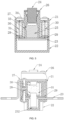
- the housing is formed by hermetically combining a first sub-housing 1 and a second sub-housing 2 which are provided on the left and right.
- a partial accommodating cavity for accommodating the first conductive terminal 3 and the second conductive terminal 4 is provided in an upper portion of the first sub-housing 1 and the second sub-housing 2, respectively.
- a first cavity 12 is provided in the housing between the first conductive terminal 3 and the second conductive terminal 4, and a second cavity 13 in communication with the first cavity 12 is provided in the housing below the first cavity 12.
- the first cavity 12 and the second cavity can be divided into two parts, and are separately provided in the first sub-housing 1 and the second sub-housing 2.
- the separated partial cavities are also accordingly combined to form a complete first cavity 12 and a complete second cavity.
- the first cavity 12 and the second cavity may also be separately provided on the first sub-housing 1 or the second sub-housing 2.
- a drive member 5 and a piston 6 are sequentially provided from top to bottom in the first cavity 12 between the first conductive terminal 3 and the second conductive terminal 4.
- An inner diameter of a part where the piston 6 is located is greater than an inner diameter of a part where the drive member 5 is located, and a transverse partition is provided in the first cavity 12 at a position between the piston 6 and the drive member 5.
- a limiting groove 14 is provided on an inner wall of the first cavity 12 at a position opposite to the piston 6, a limiting bump 15 is provided on the piston 6, and the limiting bump 15 on the piston 6 is clamped in the limiting groove 14 to limit an initial position of the piston 6.
- the drive member 5 is a miniature pneumatic device, and it can receive an excitation signal from the outside, and release a high-pressure gas, thereby driving the piston 6 to move downwards against the limiting effect.
- Closed chambers are respectively provided at two sides of the cavity mounted with the drive member 5 and the piston 6 right below the first conductive terminal 3 and the second conductive terminal 4.
- Each closed chamber may include two parts respectively located in the first sub-housing 1 and the second sub-housing 2, and the first sub-housing 1 and the second sub-housing 2 are butt-jointed to form a complete closed chamber.
- one complete closed chamber can be provided in the first sub-housing 1
- another complete closed chamber can be provided in the second sub-housing 2, so that the assembled housing includes two opposite closed chambers.
- connection conductive terminal 7 may be provided in the second cavity, and abut against a bottom surface of the closed chamber.
- the piston 6 is located right above the connection conductive terminal 7.
- a guide post 8 is provided in the second cavity, and the guide post 8 has a lower end fixed to a bottom of the housing, and an upper end fixed on a transverse partition in the first cavity 12 between the piston 6 and the drive member 5.
- the piston 6 and the connection conductive terminal 7 are respectively sleeved on the guide post 8, and can perform an up-and-down displacement motion along the guide post 8 under the action of an external force.
- the guide post 8 as a guide member, guides the connection conductive terminal 7 and the piston 6 to move smoothly downward along a predetermined path.
- the guide member may also be a longitudinal guide groove provided in the second cavity, and the connection conductive terminal 7 and the piston 6 are respectively slidably provided in the guide groove.
- a first fusant 9a and a second fusant 9b are provided in a penetrating manner in the closed chambers below the first conductive terminal 3 and the second conductive terminal 4, respectively, the first fusant 9a located below the first conductive terminal 3 has an upper end connected to the first conductive terminal 3, and a lower end connected to the connection conductive terminal 7; and the second fusant 9b located below the second conductive terminal 4 has an upper end connected to the second conductive terminal 4, and a lower end connected to the connection conductive terminal 7.
- the first conductive terminal 3, the first fusant 9a, the connection conductive terminal 7, the second fusant 9b, and the second conductive terminal 4 are connected in series to form a conductive structure of the whole fuse.
- the arc extinguishing filler 10 is filled in each closed chamber.
- the first fusant 9a and the second fusant 9b may be provided with a weak portion 11 thereon, and the weak portion 11 is located in the closed chamber, ensuring that arcs generated after the first fusant 9a and the second fusant 9b are broken are extinguished in the arc extinguishing filler 10.
- connection conductive terminal 7 When the piston 6 impacts the connection conductive terminal 7 and drives the connection conductive terminal 7 to move downwards, it can be ensured that the first fusant 9a and the second fusant 9b are broken immediately, thereby disconnecting the circuit, and protecting the circuit.
- the piston 6, driven by the drive member 5 impacts downwards the connection conductive terminal 7, the connection conductive terminal 7 can be displaced downwards along the guide post 8 to the bottom of the second cavity.
- the space of the second cavity should at least satisfy that the fusant 9 can be broken when the connection conductive terminal 7 is moved.
- the vehicle When the fuse is used on a vehicle, the vehicle is in a normal operation state, a vehicle control system does not send an excitation signal, and the drive member 5 is in a standby state. At this time, a current flows in from the first conductive terminal 3, passes through the first fusant 9a, the connection conductive terminal 7, and the second fusant 9b in sequence, and flows out from the second conductive terminal 4.
- the vehicle control system sends an excitation signal to the drive member 5, the drive member 5 operates and pushes the piston 6, the piston 6 drives the connection conductive terminal 7 to move downwards, and the connection conductive terminal 7, in the process of moving downwards, pulls the first fusant 9a and the second fusant 9b, causing the first fusant 9a and the second fusant 9b to be broken at the weak portion 11, and the arcs generated at the fracture is quickly extinguished with the aid of the surrounding arc extinguishing filler 10.
- the connection conductive terminal 7 brings the fractured fusant 9 to continue to move downwards along the guide post 8, and stops at the bottom of the second cavity. The circuit of the vehicle is cut off, completing the protection to the system circuit.
- the dimension of the product is relatively small.
- the dimension of a main body portion (the dimension of the main body does not include the dimension of overlap-joint copper busbar portions at two sides, similarly below) is 54 mm (length) * 50 mm (width) * 72 mm (height), and a rated voltage of 1000 VDC and a rated current of 400 A are designed.
- the partial resistance of the first fusant 9a and the second fusant 9b is less than 0.03 m ⁇ , and the overall resistance of the product is less than 0.1 m ⁇ , under a current of 400 A, the heat loss power thereof is less than 16 W.
- the total weight of the product is less than 550 g.
- the current range that can be protected is 0-10000 A
- the action time is 2 ms.
- the action time is fixed, irrelevant to the magnitude of the fault current.
- the impact resistance at 1500 A/5 ms can be up to 100000 times or more.
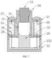
- the fuse housing is formed by combining a first sub-housing 21 and a second sub-housing 22 which are provided in a vertical direction, a first conductive terminal 27 is inserted into the first sub-housing 21 located in an upper portion, and a second conductive terminal 23 is inserted into the second sub-housing 22 located in a lower part.
- the first conductive terminal 27 and the second conductive terminal 23 include parts spaced apart and facing each other, and the to-be-broken portion 232 is provided on a part of the second conductive terminal 23 opposite to the first conductive terminal 27.
- the to-be-broken portion 232 may be obtained by providing the weak portion 231 on the second conductive terminal 23, wherein the weak portion 231 may be a structure such as a through hole or a breaking groove that extends in a width direction of the second conductive terminal 23 and is located at two ends of the to-be-broken portion 232.
- the breaking groove can be in a V shape, U shape or other shapes.
- the overall thickness of the to-be-broken portion 232 may be less than the thickness of the rest parts, which also can make the to-be-broken portion 232 separated from the second conductive terminal 23 when being impacted.
- a through cavity is provided on the first sub-housing 21, and a drive member 24 and a piston 25 (equivalent to the impact member) are sequentially provided in the cavity from top to bottom.
- the drive member 24 is fixed in the cavity through a limiting step and a pressing plate 26, a cavity portion of the first sub-housing 21 for accommodating the drive member 24 protrudes towards an upper part of the first sub-housing 21, and the first conductive terminal 27 is provided in a protruding portion of the first sub-housing 21 in a penetrating manner, and is fixed on the first sub-housing 21 through a screw.
- the piston 25 is fixed at an initial position in the cavity through the limiting groove 33 and the limiting bump 34, and the limiting groove 33 and the limiting bump 34 may be in the same structure as the limiting groove 14 and the limiting bump 15 in FIG. 1 to FIG. 3 .
- the piston 25 is located right above the to-be-broken portion 232 of the second conductive terminal 23.
- the two closed chambers can be provided in the first sub-housing 21, an opening can be provided on the closed chambers, a sealing plug 28 is filled in the opening, and the first fusant 30a and the second fusant 30b pass through the sealing plug 28 to be connected to the second conductive terminal 23.
- the sealing plug 28 can ensure effective sealing of the fusant 30 and the arc extinguishing filler 31, and also allow the broken portion of the fusant 30, after being broken, to slide outwards, and the arc extinguishing filler 31 does not significantly leak when the fusant 30 is pulled out.
- the second conductive terminal 23 may contact a bottom surface of the first sub-housing 21.
- an insulating plate 29 may be further provided between contact surfaces of the second conductive terminal 23 and the first sub-housing 21.
- the insulating plate 29 can prevent the sealing plug 28 from sliding outwards, can effectively assist the fusant 30 to dissipate heat, and can assist in generating gas and expand to squeeze the region, to assist in arc extinguishing, when the fusant 30 is broken and then slides outwards.
- a cavity is provided in the second sub-housing 22 for the to-be-broken portion 232 to fall downwards with the broken arc-extinguished fusant 30 after being broken, so that the to-be-broken portion 232 can move downwards to break the fusant 30.
- the first fusant 30a passes through the insulating plate 29, one closed chamber, and the sealing plug 28, and has an upper end connected to a part of the first conductive terminal 27, and a lower end connected to a part of the to-be-broken portion 232 on the second conductive terminal 23.
- the second fusant 30b passes through the insulating plate 29, the other closed chamber, and the sealing plug 28 thereon, and has an upper end connected to another part of the first conductive terminal 27, and a lower end connected to another part of the to-be-broken portion 232 on the second conductive terminal 23.
- the first fusant 30a and the second fusant 30b are connected in parallel between the first conductive terminal 27 and the second conductive terminal 23.
- the first fusant 30a may include a fusant to be broken first and a fusant to be broken later that are connected in parallel
- the second fusant 30b may include a fusant to be broken first and a fusant to be broken later that are connected in parallel.
- the cross-section of the fusant can be made smaller, or more or larger fractures or narrow paths can be provided on the fusant, so that the fusant is broken first when being subjected to a force.
- the vehicle control system When the vehicle is in the normal operation state, the vehicle control system does not send the excitation signal, therefore the drive member 24 is in the standby state; at this time, the current flows in from the first conductive terminal 27, passes through the first fusant 30a and the second fusant 30b connected in parallel, and then flows out from the second conductive terminal 23.
- the vehicle control system sends the excitation signal to the drive member 24, the drive member 24 operates and pushes the piston 25 to move downwards, the piston 25 impacts the to-be-broken portion 232 on the second conductive terminal 23, and the to-be-broken portion 232 is broken at the weak portion 231; the to-be-broken portion 232 continues to move downwards under the push of the piston 25, and pulls the first fusant 30a and the second fusant 30b to be broken at the weak portion 231 during the movement.
- the arcs generated at the fractures of the first fusant 30a and the second fusant 30b are quickly extinguished with the aid of the surrounding arc extinguishing filler 31.
- the to-be-broken portion 232 continues to move downwards with the broken fusant 30, and is finally buffered and stopped at a predetermined position with the help of the second sub-housing 22.
- the circuit of the vehicle is cut off, completing the protection to the system circuit.
- the product has a relatively small dimension, and taking the main body portion having a dimension of 54 mm (length) * 50 mm (width) * 72 mm (height) as an example, a rated voltage of 1000 VDC and a rated current of 400 A are designed.
- the partial resistance of the fusant 30 is less than 0.03 m ⁇ , and the parallel connection manner is adopted, the overall resistance of the product is predicted to be less than 0.05 m ⁇ , and under a current of 400 A, the heat loss power thereof is 8 W.
- the overall weight of the product is less than 550 g.
- the current range that can be protected is 0-10000 A, and the action time is 2 ms. The action time is fixed, irrelevant to the magnitude of the fault current.
- the impact resistance at 1500 A/5 ms can be up to 100000 times or more.
- the conventional thermal fuse in order to realize the rated current of 400 A at 1000 VDC, the conventional thermal fuse has a main body dimension of 80 mm (length) * 60 mm (width) * 60 mm (height), a resistance of about 0.180 m ⁇ , and an operating power of 28.8 W under long-term current of 400 A.
- the fuse has a weight over 700 g.
- the current range that can be protected is 2500-10000 A
- the action time is 1000-2 ms.
- the action time decreases with the current increase, and the action cannot be ensured below 2500 A.
- the impact resistance at 1500 A/5 ms is 500-1000 times.
- the product resistance is 0.040 m ⁇ , and the operating power is 6.4 W under long-term current of 400 A.
- the product has a weight of 500 g, the main body dimension of the whole product is 70*70*110 mm, and the dimension is relatively larger.
- the current range that can be protected is 0-10000 A, and action time is 2 ms. The action time is fixed, irrelevant to the magnitude of the fault current.
- the impact resistance at 1500 A/5 ms is more than 100000 times. Without auxiliary means, the volume of the product will be increased significantly as the voltage increases.
- the product resistance is 0.040 m ⁇ , and the operating power is 6.4 W under long-term current of 400 A.
- the product has a weight less than 550 g, and the main body dimension of the whole product is 54*50*72 mm.
- the current range that can be protected is 1000 A-20000 A, and the action time is 2 ms. The action time is fixed, irrelevant to the magnitude of the fault current.
- the impact resistance at 1500 A/5 ms is 100000 times or more. This solution can hardly provide protection to the system at 0-1000 A.
- the fuse solution of the present disclosure can effectively improve various performances of the excitation fuse. Meanwhile, the costs are not significantly increased.
- the present disclosure has the following advantages: the product has a small resistance, low heat generation, and low power consumption; can support zero-current cut-off, and can quickly and reliably disconnect large and small fault currents; the product has a higher anti-current-impact capability; the product is less affected by air pressure, temperature and humidity, and can be reliably disconnected in various operating conditions; a production process of a fuse can be directly used for the product, and the product is mature and has high reliability; the breaking capacity of the product can be adjusted according to requirements; the breaking capacity of the product after long-term use is not obviously aged; and the breaking is completely controlled, and the system can adjust the breaking by itself according to actual operating conditions.
- the first conductive terminal 41 and the second conductive terminal 42 are provided on left and right sides of the upper portion of the housing 43 spaced apart from and opposite to each other.
- the upper portion of the housing 43 is provided with two closed chambers 46 spaced apart from and opposite to each other, and the two closed chambers 46 are respectively located in lower parts of the first conductive terminal 41 and the second conductive terminal 42.
- the closed chamber 46 on the left is provided with a first fusant 48 to be broken first and a first fusant 47 to be broken later in a penetrating manner
- the closed chamber 46 on the right is provided with a second fusant 58 to be broken first and a second fusant 57 to be broken later in a penetrating manner.
- a connection conductive terminal 52 is provided in a cavity in a lower part of the housing 43, the first fusant 48 to be broken first and the first fusant 47 to be broken later each have an upper end connected to the first conductive terminal 41, and a lower end connected to a left end of the connection conductive terminal 52.
- the second fusant 58 to be broken first and the second fusant 57 to be broken later each have an upper end connected to the second conductive terminal 42, and a lower end connected to a right end of the connection conductive terminal 52.
- the first conductive terminal 41, the first fusants 47, 48, the connection conductive terminal 52, the second fusants 57, 58, and the second conductive terminal 42 are sequentially connected in series.
- the first fusants 47, 48 include two fusants connected in parallel and successively broken.
- the second fusants 57, 58 include two fusants connected in parallel and successively broken.
- the impact apparatus includes a drive member 44 and a piston 45 (in this embodiment, the piston 45 is used as an impact member), and the piston 45 is opposite to the connection conductive terminal 52. Moreover, a side wall of the piston 45 cooperates with the fusant punch 51, and when moving downwards, the piston 45 can drive the fusant punch 51 to move towards the interior of the closed chamber 46, to break the fusant by impacting. In the above, the fusant punch 51 is opposite to the weak portion 49 of the fusant to be broken first.
- the drive member 44 drives the piston 45 to move downwards. Meanwhile, the fusant punch 51 breaks the first fusant 48 to be broken first by impacting. Then the piston 45 continues to move downwards, and as a zigzag portion 50 is provided on the first fusant 47 to be broken later and the second fusant 57 to be broken later, the piston 45 pushes the connection conductive terminal 52 to continue to move downwards for a certain distance so that the fuse is completely broken when the first fusant 47 to be broken later and the second fusant 57 to be broken later are broken.
- Contact surface of the side wall of the piston 45 and the fusant punch 51 may be beveled surface, such that the piston, when moving downwards, drives the fusant punch 51 to transversely move to break the first fusant 48 to be broken first by impacting.
- the first fusant 48 is first broken by impacting by the fusant punch 51 in the closed chamber 46, no spark will be generated in the arc extinguishing filler environment of the closed chamber 46, and at this time, the circuit still remains in an on state. Thereafter, the first fusant 47 to be broken later and the second fusant 57 to be broken later can be broken under the action of a pulling force, or can be thermally fused due to current increase. No spark will be generated at the breaking position in the arc extinguishing filler environment in the closed chamber 46.
- a cross-sectional dimension of the fusant to be broken first can be larger than that of the fusant to be broken later, so that the fusant to be broken first withstands a larger current in a normal operation state.
- the fusant to be broken later can be rapidly broken under dual function of thermal fusing effect of current increase and pulling force.
- the fusant to be broken later has a smaller cross-sectional dimension, and is in more sufficient contact with the arc extinguishing filler, then the arc extinguishing effect in the breaking is better. With such configuration, the power consumption can be reduced, and the large current breaking capacity can be improved.
- a separating plate 56 can be provided in the closed chamber 46, and the separating plate 56 is located between the fusant to be broken first and the fusant to be broken later, and separates the two from each other, so that the fusant to be broken first, when being broken, does not affect the fusant to be broken later.
- a buffer member 54 may be provided at a position of the bottom of the housing 43 opposite to the connection conductive terminal 52, so that the impact force of the connection conductive terminal 52 when falling to the bottom is smaller.
- a support member 53 may be provided at a position of an inner side wall of the housing 43 opposite to the connection conductive terminal 52, and is configured to support the connection conductive terminal 52, so that it is maintained at a preset position in the housing 43 in a normal operation state, thereby avoiding the generation of a pulling force on the fusant, and not affecting the normal operation state of the fusant.
- a sealing plug 55 is provided at a position where the fusant passes through the closed chamber 46, which will not be repeated herein.
- an embodiment provides a circuit system, including any one of the above fuses.
- the circuit system as including any one of the above fuses, also has the technical effects described in the above, and details are not repeated herein
- the fuse and the circuit system in the present disclosure can reduce the magnitudes of current and acting force acting on each fusant, so that the state of the fuse in the normal operation state is stable, the fusants, when being in the normal operation, can withstand a larger current as a whole, and when being broken, are broken in sequence, then it is easier to disconnect a large current, the power consumption can be reduced, the large current breaking capacity is improved, moreover, an additional conductive terminal does not need to be introduced into the circuit, simplifying the circuit structure, delaying the disconnection, further reducing the power consumption, and improving the large current breaking capacity.
Landscapes
- Fuses (AREA)
Claims (11)
- Sicherung, umfassend:ein Gehäuse (43), eine geschlossene Kammer (46), die im Gehäuse (43) bereitgestellt ist, wobei die geschlossene Kammer (46) mit einem Lichtbogenlöschmittel (10, 31) gefüllt ist, und ein erster leitender Anschluss (3, 27, 41) und ein zweiter leitender Anschluss (4, 23, 42), die jeweils als Stromeingangsende und Stromausgangsende dienen und mit dem Gehäuse (43) verbunden sind;eine Schmelzvorrichtung (9, 30), die in Reihe zwischen dem ersten leitenden Anschluss (3, 27, 41) und dem zweiten leitenden Anschluss (4, 23, 42) geschaltet ist und mindestens teilweise in der geschlossenen Kammer (46) in durchdringender Weise bereitgestellt ist; undeine Aufpralleinrichtung, die in dem Gehäuse (43) bereitgestellt ist, sich außerhalb der geschlossenen Kammer (46) befindet und so ausgestaltet ist, dass sie bei Empfang eines Erregungssignals auf die Schmelzvorrichtung (9, 30) einwirkt und eine Aufprallkraft erzeugt, welche die Schmelzvorrichtung (9, 30) in der geschlossenen Kammer (46) zerbricht;wobei eine Vielzahl geschlossener Kammern (46) und ein entsprechender Schmelzabschnitt (9, 30) in jeder geschlossenen Kammer (46) in durchdringender Weise bereitgestellt sind und die Vielzahl von Schmelzabschnitten (9, 30), die in der Vielzahl geschlossener Kammern (46) in durchdringender Weise bereitgestellt sind, in Reihe oder parallel geschaltet sind;wobei jeder Schmelzabschnitt eine Vielzahl parallel geschalteter Schmelzelemente (47, 48, 57, 58) umfasst, wobei die Vielzahl von Schmelzelementen (47, 48, 57, 58) in jeder geschlossenen Kammer (46) in durchdringender Weise bereitgestellt ist, dadurch gekennzeichnet, dass die Vielzahl parallel geschalteter Schmelzelemente als ein erstes Schmelzelement (48, 58), das zuerst zu brechen ist, und als ein zweites Schmelzelement (47, 57), das später zu brechen ist, bereitgestellt ist;wobei die Sicherung ferner einen Schmelzstift (51) umfasst, der Schmelzstift (51) an einer Außenwand der geschlossenen Kammer (46) in dynamisch dichtender Weise bereitgestellt ist, wobei ein Ende mit der Aufpralleinrichtung verbunden ist und das andere Ende dem ersten, zuerst zu brechenden Schmelzelement gegenüberliegt und so konfiguriert ist, dass es sich bewegt und das erste, zuerst zu brechende Schmelzelement durch Aufprall bricht, wenn die Aufpralleinrichtung wirkt; undwobei das später zu brechende zweite Schmelzelement mit einem Zickzack-Abschnitt bereitgestellt ist, der so konfiguriert ist, dass er nach dem Ausdehnen auf eine vorbestimmte Länge bricht.
- Sicherung nach Anspruch 1, wobei der Zickzack-Abschnitt eine S-förmige Wellenstruktur oder eine Spiralstruktur aufweist.
- Sicherung nach einem der Ansprüche 1 bis 2, wobei ein schwacher Teil (11, 231, 49) an einer Position bereitgestellt ist, an der sich das Schmelzelement in der geschlossenen Kammer (46) befindet, sodass das Schmelzelement am schwachen Teil (11, 231, 49) bricht, wenn es einem Aufprall ausgesetzt ist, wobei eine Struktur des schwachen Teils (11, 231, 49) vorzugsweise ein Durchgangsloch oder eine Bruchnut ist.
- Sicherung nach einem der Ansprüche 1 bis 3, wobei die Aufpralleinrichtung ein Antriebsteil (5, 24, 44) und ein Aufprallteil umfasst, wobei das Antriebsteil (5, 24, 44) ausgestaltet ist, um das Aufprallteil bei Empfang eines Erregungssignals zum Wirken anzutreiben, wobei das Erregungssignal bei einem erfassten Fehlerstrom oder als Reaktion auf eine Benutzerbetätigung gesendet wird; und
wobei das Aufprallelement so konfiguriert ist, dass es eine Zugkraft auf das Schmelzelement erzeugt und so wirkt, dass das Schmelzelement unter der Zugkraft bricht. - Sicherung nach einem der Ansprüche 1 bis 4, wobei zwei geschlossene Kammern (46) bereitgestellt sind, die beiden geschlossenen Kammern (46) voneinander beabstandet sind und einander gegenüber liegen und die Schmelzvorrichtung (9, 30) einen ersten Schmelzabschnitt und einen zweiten Schmelzabschnitt umfasst, die jeweils in den beiden geschlossenen Kammern (46) in durchdringender Weise bereitgestellt sind; und
die Aufpralleinrichtung sich zwischen den beiden geschlossenen Kammern (46) befindet. - Sicherung nach Anspruch 5, wobei der erste leitende Anschluss (3, 27, 41) und der zweite leitende Anschluss (4, 23, 42) jeweils von zwei Seiten des Gehäuses (43) in das Gehäuse (43) eingeführt sind, wobei die Sicherung weiterhin einen im Gehäuse (43) bereitgestellten leitenden Verbindungsanschluss (7, 52) umfasst, wobei der erste Schmelzabschnitt zwischen dem ersten leitenden Anschluss (3, 27, 41) und dem leitenden Verbindungsanschluss (7, 52) angeschlossen ist und der zweite Schmelzabschnitt zwischen dem zweiten leitenden Anschluss (4, 23, 42) und dem leitenden Verbindungsanschluss (7, 52) angeschlossen ist; und
wobei die Aufpralleinrichtung dem leitenden Anschluss (7, 52) gegenüberliegt und so konfiguriert ist, dass sie auf den leitenden Anschluss (7, 52) aufprallt und ihn bewegt, was die Schmelzvorrichtung (9, 30) bricht. - Sicherung nach Anspruch 5 oder 6, wobei die Sicherung weiterhin ein Führungselement umfasst, das so konfiguriert ist, dass es die Aufpralleinrichtung und den leitenden Anschluss (7, 52) führt.
- Sicherung nach einem der Ansprüche 5 bis 7, wobei der zweite leitende Anschluss (4, 23, 42) einen zu zerbrechenden Teil (232) umfasst, wobei der zu zerbrechende Teil (232) von dem ersten leitenden Anschluss (3, 27, 41) beabstandet ist und diesem gegenüberliegt;wobei der erste Schmelzabschnitt und der zweite Schmelzabschnitt jeweils ein Ende aufweisen, das mit dem ersten leitenden Anschluss (3, 27, 41) verbunden ist, und wobei das andere Ende mit dem zu zerbrechenden Teil (232) verbunden ist; undwobei die Aufpralleinrichtung dem zu zerbrechenden Teil (232) gegenüberliegt und so ausgestaltet ist, dass sie auf den zu zerbrechenden Teil (232) aufprallt und ihn bewegt, was die Schmelzvorrichtung (9, 30) bricht.
- Sicherung nach einem der Ansprüche 1 bis 8, wobei die geschlossene Kammer (46) mit einer Öffnung bereitgestellt ist, ein Verschlussstopfen (28, 55) in der Öffnung bereitgestellt ist und der Schmelzabschnitt durch den Verschlussstopfen (28, 55) hindurchgeht, um in die geschlossene Kammer (46) einzutreten oder die geschlossene Kammer (46) zu verlassen.
- Sicherung nach einem der Ansprüche 1 bis 9, wobei das Lichtbogenlöschmittel (10, 31) ein festes Lichtbogenlöschmittel ist, das Siliziumdioxid enthält.
- Schaltkreissystem, dadurch gekennzeichnet, dass es die Sicherung nach einem der Ansprüche 1 bis 10 umfasst.
Applications Claiming Priority (3)
| Application Number | Priority Date | Filing Date | Title |
|---|---|---|---|
| CN202010263397.9A CN111341627A (zh) | 2020-04-07 | 2020-04-07 | 一种集成机械力断开灭弧熔体的激励熔断器 |
| CN202110316698.8A CN112908805B (zh) | 2020-04-07 | 2021-03-24 | 熔断器和电路系统 |
| PCT/CN2021/085832 WO2021204165A1 (zh) | 2020-04-07 | 2021-04-07 | 熔断器和电路系统 |
Publications (4)
| Publication Number | Publication Date |
|---|---|
| EP4075472A1 EP4075472A1 (de) | 2022-10-19 |
| EP4075472A4 EP4075472A4 (de) | 2023-05-31 |
| EP4075472B1 true EP4075472B1 (de) | 2025-05-28 |
| EP4075472C0 EP4075472C0 (de) | 2025-05-28 |
Family
ID=71187537
Family Applications (1)
| Application Number | Title | Priority Date | Filing Date |
|---|---|---|---|
| EP21784797.9A Active EP4075472B1 (de) | 2020-04-07 | 2021-04-07 | Sicherung und schaltkreissystem |
Country Status (8)
| Country | Link |
|---|---|
| US (1) | US12131880B2 (de) |
| EP (1) | EP4075472B1 (de) |
| JP (1) | JP7395003B2 (de) |
| KR (1) | KR102855941B1 (de) |
| CN (2) | CN111341627A (de) |
| ES (1) | ES3031308T3 (de) |
| HU (1) | HUE071657T2 (de) |
| WO (1) | WO2021204165A1 (de) |
Families Citing this family (19)
| Publication number | Priority date | Publication date | Assignee | Title |
|---|---|---|---|---|
| CN111341627A (zh) * | 2020-04-07 | 2020-06-26 | 西安中熔电气股份有限公司 | 一种集成机械力断开灭弧熔体的激励熔断器 |
| CN111739770B (zh) * | 2020-07-15 | 2022-04-12 | 国网甘肃省电力公司兰州供电公司 | 一种二次送电的自复熔断器 |
| CN113223905B (zh) * | 2020-12-11 | 2024-01-19 | 西安中熔电气股份有限公司 | 一种熔断兼机械力断开熔体式熔断器 |
| CN112447461A (zh) | 2020-12-11 | 2021-03-05 | 西安中熔电气股份有限公司 | 一种依次断开导体和熔体的激励熔断器 |
| CN112447462B (zh) * | 2020-12-11 | 2025-07-22 | 西安中熔电气股份有限公司 | 一种机械打断及熔断组合多断口激励熔断器 |
| CN112447463B (zh) * | 2020-12-11 | 2025-06-10 | 西安中熔电气股份有限公司 | 一种分组断开的多断口激励熔断器 |
| CN115602505B (zh) * | 2021-06-25 | 2024-10-11 | 比亚迪股份有限公司 | 熔断器 |
| CN113851336B (zh) * | 2021-10-27 | 2025-11-18 | 西安中熔电气股份有限公司 | 一种单激励源分步动作的激励保护装置 |
| CN116137218A (zh) * | 2021-11-18 | 2023-05-19 | 西安中熔电气股份有限公司 | 一种并联熔体的激励保护装置 |
| CN114300321A (zh) * | 2022-01-07 | 2022-04-08 | 西安中熔电气股份有限公司 | 一种高电压、小体积激励熔断器 |
| CN114300320B (zh) * | 2022-02-09 | 2025-06-27 | 西安中熔电气股份有限公司 | 一种集成了激励熔断器和继电器保护功能的电路保护器件 |
| CN118231200A (zh) * | 2023-08-15 | 2024-06-21 | 比亚迪股份有限公司 | 激励熔断器、电力设备及车辆 |
| CN117334541B (zh) * | 2023-12-01 | 2024-03-19 | 杭州高特电子设备股份有限公司 | 一种主动断开熔断器及断开方法 |
| EP4625458A1 (de) * | 2024-03-26 | 2025-10-01 | Miba Resistors Austria GmbH | Elektrische schaltung mit einem elektrischen bauelement sowie dieses elektrische bauelement |
| GB2641741A (en) * | 2024-06-10 | 2025-12-17 | Gkn Aerospace Services Ltd | Apparatus |
| CN118571723B (zh) * | 2024-08-02 | 2025-01-14 | 比亚迪股份有限公司 | 熔断器、电池系统及用电设备 |
| CN119252722B (zh) * | 2024-11-21 | 2025-11-21 | 浙江中贝能源科技有限公司 | 激励熔断器及电子电路 |
| CN119786323B (zh) * | 2025-03-12 | 2025-05-16 | 浙江中贝能源科技有限公司 | 主被动一体保护的激励熔断器及相关装置 |
| CN120048698B (zh) * | 2025-04-24 | 2025-07-22 | 浙江中贝能源科技有限公司 | 用于三相电路保护的激励打断器 |
Family Cites Families (19)
| Publication number | Priority date | Publication date | Assignee | Title |
|---|---|---|---|---|
| US4307369A (en) | 1980-09-19 | 1981-12-22 | S&C Electric Company | High-voltage fuse cutout |
| JPH10241546A (ja) * | 1997-02-27 | 1998-09-11 | Hinode Denki Seisakusho:Kk | 自己消弧装置 |
| DE19817133A1 (de) * | 1998-04-19 | 1999-10-28 | Lell Peter | Powerswitch |
| CN102290301B (zh) * | 2010-06-18 | 2014-04-02 | 厦门赛尔特电子有限公司 | 一种大电流熔断器 |
| CN101950715A (zh) * | 2010-10-08 | 2011-01-19 | Aem科技(苏州)有限公司 | 一种慢断型表面贴装熔断器及其制作工艺 |
| JP5056941B2 (ja) * | 2010-12-27 | 2012-10-24 | ダイキン工業株式会社 | 切断装置 |
| JP2014049300A (ja) * | 2012-08-31 | 2014-03-17 | Toyoda Gosei Co Ltd | 導通遮断装置 |
| JP5817685B2 (ja) * | 2012-08-31 | 2015-11-18 | 豊田合成株式会社 | 導通遮断装置 |
| DE102014115396A1 (de) * | 2014-10-22 | 2014-12-18 | Peter Lell | Trennschalter für hohe Gleich- oder Wechselströme bei hohen Spannungen |
| DE102015114279A1 (de) * | 2015-08-27 | 2015-10-15 | Peter Lell | Trennschalter für hohe Gleich- oder Wechselströme bei hohen Spannungen mit in Reihe geschalteten Verbindungselementen |
| CN205140788U (zh) * | 2015-11-13 | 2016-04-06 | 国联汽车动力电池研究院有限责任公司 | 大电流开关及电路 |
| DE102017119285A1 (de) * | 2017-02-01 | 2018-08-02 | Dehn + Söhne Gmbh + Co. Kg | Triggerbare Schmelzsicherung für Niederspannungsanwendungen |
| CN207303031U (zh) * | 2017-05-20 | 2018-05-01 | 深圳市威可特电子科技有限公司 | 新能源车用多芯高可靠性熔断器 |
| JP6873857B2 (ja) * | 2017-07-28 | 2021-05-19 | 株式会社ダイセル | 並列回路を有する電気回路遮断装置 |
| FR3073664B1 (fr) * | 2017-11-14 | 2019-12-06 | Arianegroup Sas | Dispositif de coupure pyrotechnique |
| CN207690743U (zh) * | 2017-12-05 | 2018-08-03 | 深圳市比亚迪锂电池有限公司 | 熔断器及具有其的电池包 |
| CN109148237A (zh) * | 2018-09-21 | 2019-01-04 | 北京中电安智科技有限公司 | 一种熔丝切割器及新型跌落式熔断器 |
| CN110854000A (zh) | 2019-12-16 | 2020-02-28 | 西安中熔电气股份有限公司 | 一种集成灭弧熔体的激励熔断器 |
| CN111341627A (zh) * | 2020-04-07 | 2020-06-26 | 西安中熔电气股份有限公司 | 一种集成机械力断开灭弧熔体的激励熔断器 |
-
2020
- 2020-04-07 CN CN202010263397.9A patent/CN111341627A/zh active Pending
-
2021
- 2021-03-24 CN CN202110316698.8A patent/CN112908805B/zh active Active
- 2021-04-07 KR KR1020227025366A patent/KR102855941B1/ko active Active
- 2021-04-07 ES ES21784797T patent/ES3031308T3/es active Active
- 2021-04-07 WO PCT/CN2021/085832 patent/WO2021204165A1/zh not_active Ceased
- 2021-04-07 JP JP2022542072A patent/JP7395003B2/ja active Active
- 2021-04-07 EP EP21784797.9A patent/EP4075472B1/de active Active
- 2021-04-07 US US17/799,745 patent/US12131880B2/en active Active
- 2021-04-07 HU HUE21784797A patent/HUE071657T2/hu unknown
Also Published As
| Publication number | Publication date |
|---|---|
| HUE071657T2 (hu) | 2025-09-28 |
| US20230352252A1 (en) | 2023-11-02 |
| WO2021204165A1 (zh) | 2021-10-14 |
| EP4075472A4 (de) | 2023-05-31 |
| JP2023510299A (ja) | 2023-03-13 |
| CN111341627A (zh) | 2020-06-26 |
| US12131880B2 (en) | 2024-10-29 |
| ES3031308T3 (en) | 2025-07-07 |
| CN112908805A (zh) | 2021-06-04 |
| KR20220108198A (ko) | 2022-08-02 |
| CN112908805B (zh) | 2022-05-20 |
| JP7395003B2 (ja) | 2023-12-08 |
| EP4075472C0 (de) | 2025-05-28 |
| KR102855941B1 (ko) | 2025-09-04 |
| EP4075472A1 (de) | 2022-10-19 |
Similar Documents
| Publication | Publication Date | Title |
|---|---|---|
| EP4075472B1 (de) | Sicherung und schaltkreissystem | |
| KR102714851B1 (ko) | 도체와 가용체를 순차적으로 파단하는 여기 퓨즈 | |
| CN110494946B (zh) | 用于低压应用的可触发式的熔断保险装置 | |
| JP7316367B2 (ja) | 機械切断及び溶断の組み合わせを利用した複数破断口誘起ヒューズ | |
| CN211980553U (zh) | 一种集成机械力断开灭弧熔体的激励熔断器 | |
| WO2022121232A1 (zh) | 一种机械打断及熔断组合多断口激励熔断器 | |
| CN216054559U (zh) | 熔断器以及车辆 | |
| CN110491749B (zh) | 一种外部驱动型快速开关结构 | |
| JP2024128920A (ja) | 回路遮断器 | |
| CN222338184U (zh) | 一种激励集成接触器 | |
| CN222514840U (zh) | 一种集成有激励功能的接触器 | |
| CN114300320A (zh) | 一种集成了激励熔断器和继电器保护功能的电路保护器件 | |
| CN216793593U (zh) | 一种分层熔体结构及依次打断导体和分层熔体的激励保护装置 | |
| CN100377273C (zh) | 电路断路器的消弧装置 | |
| CN220796646U (zh) | 一种激励熔断器与接触器集成的保护装置 | |
| CN223539552U (zh) | 组合式灭弧智能熔断器 | |
| CN219181174U (zh) | 一种同时具备定时限保护与反时限保护的保护装置及激励保护装置 | |
| CN219658656U (zh) | 一种延时切断熔体的激励熔断器 | |
| CN222514867U (zh) | 一种具有激励功能的集成接触器 | |
| CN222887846U (zh) | 一种延时断开熔体的激励熔断器 | |
| CN220934004U (zh) | 用于智能熔断器的灭弧结构及具有其的智能熔断器 | |
| CN121075833A (zh) | 一种集成有激励功能的接触器 | |
| CN120280312A (zh) | 一种分断集成接触器 | |
| CN121096814A (zh) | 一种具有激励功能的集成接触器 | |
| CN118367510A (zh) | 一种同时具备定时限保护与反时限保护的保护装置及激励保护装置 |
Legal Events
| Date | Code | Title | Description |
|---|---|---|---|
| STAA | Information on the status of an ep patent application or granted ep patent |
Free format text: STATUS: THE INTERNATIONAL PUBLICATION HAS BEEN MADE |
|
| PUAI | Public reference made under article 153(3) epc to a published international application that has entered the european phase |
Free format text: ORIGINAL CODE: 0009012 |
|
| STAA | Information on the status of an ep patent application or granted ep patent |
Free format text: STATUS: REQUEST FOR EXAMINATION WAS MADE |
|
| 17P | Request for examination filed |
Effective date: 20220715 |
|
| AK | Designated contracting states |
Kind code of ref document: A1 Designated state(s): AL AT BE BG CH CY CZ DE DK EE ES FI FR GB GR HR HU IE IS IT LI LT LU LV MC MK MT NL NO PL PT RO RS SE SI SK SM TR |
|
| REG | Reference to a national code |
Ref country code: DE Ipc: H01H0039000000 Ref legal event code: R079 Ref document number: 602021031469 Country of ref document: DE Free format text: PREVIOUS MAIN CLASS: H01H0085380000 |
|
| STAA | Information on the status of an ep patent application or granted ep patent |
Free format text: STATUS: EXAMINATION IS IN PROGRESS |
|
| A4 | Supplementary search report drawn up and despatched |
Effective date: 20230428 |
|
| RIC1 | Information provided on ipc code assigned before grant |
Ipc: H01H 85/36 20060101ALN20230421BHEP Ipc: H01H 85/10 20060101ALN20230421BHEP Ipc: H01H 85/02 20060101ALN20230421BHEP Ipc: H01H 9/10 20060101ALI20230421BHEP Ipc: H01H 85/18 20060101ALI20230421BHEP Ipc: H01H 85/12 20060101ALI20230421BHEP Ipc: H01H 39/00 20060101AFI20230421BHEP |
|
| 17Q | First examination report despatched |
Effective date: 20230526 |
|
| DAV | Request for validation of the european patent (deleted) | ||
| DAX | Request for extension of the european patent (deleted) | ||
| GRAP | Despatch of communication of intention to grant a patent |
Free format text: ORIGINAL CODE: EPIDOSNIGR1 |
|
| STAA | Information on the status of an ep patent application or granted ep patent |
Free format text: STATUS: GRANT OF PATENT IS INTENDED |
|
| INTG | Intention to grant announced |
Effective date: 20241220 |
|
| RIC1 | Information provided on ipc code assigned before grant |
Ipc: H01H 85/36 20060101ALN20241213BHEP Ipc: H01H 85/10 20060101ALN20241213BHEP Ipc: H01H 85/02 20060101ALN20241213BHEP Ipc: H01H 9/10 20060101ALI20241213BHEP Ipc: H01H 85/18 20060101ALI20241213BHEP Ipc: H01H 85/12 20060101ALI20241213BHEP Ipc: H01H 39/00 20060101AFI20241213BHEP |
|
| GRAS | Grant fee paid |
Free format text: ORIGINAL CODE: EPIDOSNIGR3 |
|
| GRAA | (expected) grant |
Free format text: ORIGINAL CODE: 0009210 |
|
| STAA | Information on the status of an ep patent application or granted ep patent |
Free format text: STATUS: THE PATENT HAS BEEN GRANTED |
|
| AK | Designated contracting states |
Kind code of ref document: B1 Designated state(s): AL AT BE BG CH CY CZ DE DK EE ES FI FR GB GR HR HU IE IS IT LI LT LU LV MC MK MT NL NO PL PT RO RS SE SI SK SM TR |
|
| REG | Reference to a national code |
Ref country code: GB Ref legal event code: FG4D |
|
| REG | Reference to a national code |
Ref country code: CH Ref legal event code: EP |
|
| REG | Reference to a national code |
Ref country code: DE Ref legal event code: R096 Ref document number: 602021031469 Country of ref document: DE |
|
| REG | Reference to a national code |
Ref country code: IE Ref legal event code: FG4D |
|
| REG | Reference to a national code |
Ref country code: ES Ref legal event code: FG2A Ref document number: 3031308 Country of ref document: ES Kind code of ref document: T3 Effective date: 20250707 |
|
| U01 | Request for unitary effect filed |
Effective date: 20250604 |
|
| U07 | Unitary effect registered |
Designated state(s): AT BE BG DE DK EE FI FR IT LT LU LV MT NL PT RO SE SI Effective date: 20250616 |
|
| REG | Reference to a national code |
Ref country code: SK Ref legal event code: T3 Ref document number: E 46740 Country of ref document: SK |
|
| REG | Reference to a national code |
Ref country code: HU Ref legal event code: AG4A Ref document number: E071657 Country of ref document: HU |
|
| PG25 | Lapsed in a contracting state [announced via postgrant information from national office to epo] |
Ref country code: NO Free format text: LAPSE BECAUSE OF FAILURE TO SUBMIT A TRANSLATION OF THE DESCRIPTION OR TO PAY THE FEE WITHIN THE PRESCRIBED TIME-LIMIT Effective date: 20250828 Ref country code: GR Free format text: LAPSE BECAUSE OF FAILURE TO SUBMIT A TRANSLATION OF THE DESCRIPTION OR TO PAY THE FEE WITHIN THE PRESCRIBED TIME-LIMIT Effective date: 20250829 |
|
| PG25 | Lapsed in a contracting state [announced via postgrant information from national office to epo] |
Ref country code: PL Free format text: LAPSE BECAUSE OF FAILURE TO SUBMIT A TRANSLATION OF THE DESCRIPTION OR TO PAY THE FEE WITHIN THE PRESCRIBED TIME-LIMIT Effective date: 20250528 |
|
| PG25 | Lapsed in a contracting state [announced via postgrant information from national office to epo] |
Ref country code: HR Free format text: LAPSE BECAUSE OF FAILURE TO SUBMIT A TRANSLATION OF THE DESCRIPTION OR TO PAY THE FEE WITHIN THE PRESCRIBED TIME-LIMIT Effective date: 20250528 |
|
| PG25 | Lapsed in a contracting state [announced via postgrant information from national office to epo] |
Ref country code: RS Free format text: LAPSE BECAUSE OF FAILURE TO SUBMIT A TRANSLATION OF THE DESCRIPTION OR TO PAY THE FEE WITHIN THE PRESCRIBED TIME-LIMIT Effective date: 20250828 |
|
| PG25 | Lapsed in a contracting state [announced via postgrant information from national office to epo] |
Ref country code: IS Free format text: LAPSE BECAUSE OF FAILURE TO SUBMIT A TRANSLATION OF THE DESCRIPTION OR TO PAY THE FEE WITHIN THE PRESCRIBED TIME-LIMIT Effective date: 20250928 |