EP4075112B1 - Fehlerdetektionssystem - Google Patents
Fehlerdetektionssystem Download PDFInfo
- Publication number
- EP4075112B1 EP4075112B1 EP21168315.6A EP21168315A EP4075112B1 EP 4075112 B1 EP4075112 B1 EP 4075112B1 EP 21168315 A EP21168315 A EP 21168315A EP 4075112 B1 EP4075112 B1 EP 4075112B1
- Authority
- EP
- European Patent Office
- Prior art keywords
- temperature
- location
- temperature data
- sensor
- processing unit
- Prior art date
- Legal status (The legal status is an assumption and is not a legal conclusion. Google has not performed a legal analysis and makes no representation as to the accuracy of the status listed.)
- Active
Links
Images

Classifications
-
- G—PHYSICS
- G01—MEASURING; TESTING
- G01R—MEASURING ELECTRIC VARIABLES; MEASURING MAGNETIC VARIABLES
- G01R31/00—Arrangements for testing electric properties; Arrangements for locating electric faults; Arrangements for electrical testing characterised by what is being tested not provided for elsewhere
- G01R31/50—Testing of electric apparatus, lines, cables or components for short-circuits, continuity, leakage current or incorrect line connections
- G01R31/56—Testing of electric apparatus
-
- G—PHYSICS
- G01—MEASURING; TESTING
- G01K—MEASURING TEMPERATURE; MEASURING QUANTITY OF HEAT; THERMALLY-SENSITIVE ELEMENTS NOT OTHERWISE PROVIDED FOR
- G01K7/00—Measuring temperature based on the use of electric or magnetic elements directly sensitive to heat ; Power supply therefor, e.g. using thermoelectric elements
- G01K7/42—Circuits effecting compensation of thermal inertia; Circuits for predicting the stationary value of a temperature
- G01K7/427—Temperature calculation based on spatial modeling, e.g. spatial inter- or extrapolation
-
- H—ELECTRICITY
- H02—GENERATION; CONVERSION OR DISTRIBUTION OF ELECTRIC POWER
- H02B—BOARDS, SUBSTATIONS OR SWITCHING ARRANGEMENTS FOR THE SUPPLY OR DISTRIBUTION OF ELECTRIC POWER
- H02B13/00—Arrangement of switchgear in which switches are enclosed in, or structurally associated with, a casing, e.g. cubicle
- H02B13/02—Arrangement of switchgear in which switches are enclosed in, or structurally associated with, a casing, e.g. cubicle with metal casing
- H02B13/035—Gas-insulated switchgear
- H02B13/065—Means for detecting or reacting to mechanical or electrical defects
-
- G—PHYSICS
- G01—MEASURING; TESTING
- G01J—MEASUREMENT OF INTENSITY, VELOCITY, SPECTRAL CONTENT, POLARISATION, PHASE OR PULSE CHARACTERISTICS OF INFRARED, VISIBLE OR ULTRAVIOLET LIGHT; COLORIMETRY; RADIATION PYROMETRY
- G01J5/00—Radiation pyrometry, e.g. infrared or optical thermometry
- G01J5/0096—Radiation pyrometry, e.g. infrared or optical thermometry for measuring wires, electrical contacts or electronic systems
-
- G—PHYSICS
- G01—MEASURING; TESTING
- G01J—MEASUREMENT OF INTENSITY, VELOCITY, SPECTRAL CONTENT, POLARISATION, PHASE OR PULSE CHARACTERISTICS OF INFRARED, VISIBLE OR ULTRAVIOLET LIGHT; COLORIMETRY; RADIATION PYROMETRY
- G01J5/00—Radiation pyrometry, e.g. infrared or optical thermometry
- G01J5/48—Thermography; Techniques using wholly visual means
-
- G—PHYSICS
- G01—MEASURING; TESTING
- G01K—MEASURING TEMPERATURE; MEASURING QUANTITY OF HEAT; THERMALLY-SENSITIVE ELEMENTS NOT OTHERWISE PROVIDED FOR
- G01K1/00—Details of thermometers not specially adapted for particular types of thermometer
- G01K1/02—Means for indicating or recording specially adapted for thermometers
-
- G—PHYSICS
- G01—MEASURING; TESTING
- G01K—MEASURING TEMPERATURE; MEASURING QUANTITY OF HEAT; THERMALLY-SENSITIVE ELEMENTS NOT OTHERWISE PROVIDED FOR
- G01K11/00—Measuring temperature based upon physical or chemical changes not covered by groups G01K3/00, G01K5/00, G01K7/00 or G01K9/00
- G01K11/22—Measuring temperature based upon physical or chemical changes not covered by groups G01K3/00, G01K5/00, G01K7/00 or G01K9/00 using measurement of acoustic effects
- G01K11/26—Measuring temperature based upon physical or chemical changes not covered by groups G01K3/00, G01K5/00, G01K7/00 or G01K9/00 using measurement of acoustic effects of resonant frequencies
- G01K11/265—Measuring temperature based upon physical or chemical changes not covered by groups G01K3/00, G01K5/00, G01K7/00 or G01K9/00 using measurement of acoustic effects of resonant frequencies using surface acoustic wave [SAW]
-
- G—PHYSICS
- G01—MEASURING; TESTING
- G01K—MEASURING TEMPERATURE; MEASURING QUANTITY OF HEAT; THERMALLY-SENSITIVE ELEMENTS NOT OTHERWISE PROVIDED FOR
- G01K3/00—Thermometers giving results other than momentary value of temperature
-
- G—PHYSICS
- G01—MEASURING; TESTING
- G01K—MEASURING TEMPERATURE; MEASURING QUANTITY OF HEAT; THERMALLY-SENSITIVE ELEMENTS NOT OTHERWISE PROVIDED FOR
- G01K3/00—Thermometers giving results other than momentary value of temperature
- G01K3/08—Thermometers giving results other than momentary value of temperature giving differences of values; giving differentiated values
-
- G—PHYSICS
- G01—MEASURING; TESTING
- G01K—MEASURING TEMPERATURE; MEASURING QUANTITY OF HEAT; THERMALLY-SENSITIVE ELEMENTS NOT OTHERWISE PROVIDED FOR
- G01K7/00—Measuring temperature based on the use of electric or magnetic elements directly sensitive to heat ; Power supply therefor, e.g. using thermoelectric elements
- G01K7/02—Measuring temperature based on the use of electric or magnetic elements directly sensitive to heat ; Power supply therefor, e.g. using thermoelectric elements using thermoelectric elements, e.g. thermocouples
-
- G—PHYSICS
- G01—MEASURING; TESTING
- G01K—MEASURING TEMPERATURE; MEASURING QUANTITY OF HEAT; THERMALLY-SENSITIVE ELEMENTS NOT OTHERWISE PROVIDED FOR
- G01K3/00—Thermometers giving results other than momentary value of temperature
- G01K3/08—Thermometers giving results other than momentary value of temperature giving differences of values; giving differentiated values
- G01K3/14—Thermometers giving results other than momentary value of temperature giving differences of values; giving differentiated values in respect of space
- G01K2003/145—Hotspot localization
Definitions
- the present invention relates to a fault detection system and to a fault detection method.
- US2001/035825A1 relates to a method and an arrangement for recognizing potential overheating of an object. It is described that for this purpose the temperature of the object is measured by means of temperature sensors. It is described that a signal processing arrangement determines the temperature gradient from the measured temperature values. It is described that a comparator compares the determined value of the temperature gradient with a threshold value generated by a threshold value generator, and when the threshold value is exceeded, a warning signal generator triggers a warning signal. It is described that this warning signal can be an acoustical or optical signal, and that in addition or alternatively, the warning signal can activate a protective measure arrangement.
- EP3671997A1 relates to a system for monitoring a switchgear. It is described that the system comprises at least one sensor, a processing unit, and an output unit. It is described that the at least one sensor is configured to acquire temperature information data for at least two locations of a switchgear. It is described that the at least one sensor is configured to provide the processing unit with the temperature information data for the at least two locations. It is described that the processing unit is configured to determine e.g. a temperature at a new location of the switchgear different to the at least two locations, and that the determination comprises utilization of the temperature information data for the at least two locations and the relative positions of the new location and the at least two locations. It is describe that the output unit is configured to output the temperature at the new location and/or information based on the temperature at the new location.
- a temperature sensing device includes a first temperature sensor configured for mounting to a structure at a first distance relative to the structure. It is described that the temperature sensing device also includes a second temperature sensor configured for mounting to the structure at a second distance relative to the structure. It is described that the temperature sensing device also includes a processor coupled to the first and second temperature sensors and configured to estimate a third temperature based on the first and second temperatures and the distance separating the first and second temperature sensors.
- the temperature of a device e.g. Medium Voltage MV Switchgear or motor
- a device e.g. Medium Voltage MV Switchgear or motor
- Temperature measurements e.g. with IR sensors, thermocouple sensors, SAW or RFID sensors
- the measurement gives only information about the status of the temperature at the moment of the measurement and at the position of the measurement.
- Appended claim 1 defines a fault detection system.
- Appended claim 14 defines a fault detection method. The invention and its scope of protection is defined by these independent claims.
- a fault detection system comprising:
- the sensor is configured to acquire temperature data at a sensor location of a device.
- the temperature data comprises first temperature data and second temperature data acquired a first time period after the first temperature data.
- the processing unit is configured to determine a temperature magnitude comprising utilization of the first temperature data and/or the second temperature data.
- the processing unit is configured to determine a rate of change of temperature comprising utilization of the first temperature data and the second temperature data and the first time period.
- the processing unit is configured to predict a temperature at a location of the device comprising utilization of: the temperature magnitude; the rate of change of temperature; and a correlation.
- the correlation is a correlation of a plurality of temperature magnitudes and a plurality of rate of change of temperatures at the sensor location with a plurality of hotspot temperatures at the location.
- the processing unit is configured to determine if the device has a fault comprising utilization of the predicted temperature.
- the output unit is configured to output an indication that the device has a fault.
- the system detect faults and avoids overheating by using measurements of the temperature and the temperature rise rate in combination with their correlation to the hotspot temperature. This enables the early detection of future overheating of a device, a significant time before overheating occurs, and thus can be used to avoid this overheating.
- a "fault" being detected can be a detection of fault such as a loose connection determined from temperatures or could be detection of a hotspot as such.
- the processing unit is configured to determine if the device has a fault comprising a determination that the predicted temperature exceeds a threshold temperature.
- a flag can be raised if the temperature into the future is predicted to rise above a critical temperature and remedial action, such as reducing power, or even switching off the device can be undertaken.
- the processing unit is configured to select the correlation from a plurality of correlations of different operational scenarios for the device.
- Each of the plurality of correlations is a correlation of a plurality of temperature magnitudes and a plurality of rate of change of temperatures at the sensor location with a plurality of hotspot temperatures at the location.
- a series of correlations of temperatures and rate and change of temperatures can be correlated with a temperature at a hotspot location, undertaken by measurement or simulation. It can then have been established by measurement or simulation that under steady state conditions, in other words if nothing changes, that the temperature at the hot spot will rise above a critical temperature and it can be determined that the device has a fault that is leading to the heating. Then remedial action can be taken well before the overheating, that would inevitably happen if no action were to be taken, actually occurs.
- Each of these correlations can apply for example to different power operating situations, with and without different faults, in order that it can be established if overheating will occur due to a fault or if everything is in order and no overheating will occur.
- each of the plurality of correlations is determined through experiments or through simulations.
- the system comprises at least one further sensor configured to measure current and/or power.
- the current and/or the power comprises a current through the device and/or a power drawn by the device at a time of acquisition of the first temperature data and/or at a time of acquisition of the second temperature data.
- the prediction of the temperature at the location comprises utilization of the current and/or power.
- the accuracy of the fault determination through a predicted temperature is increased by taking into account other relevant operational data for the device.
- selection of the correlation comprises utilization of the current and/or power.
- the accuracy of the selecting the correlation is increased by taking into account other relevant operational data for the device.
- the temperature data comprises third temperature data and fourth temperature data acquired a second time period after the third temperature data, and where the second time period is over a different time period to the first time period.
- the processing unit is configured to determine a second temperature magnitude comprising utilization of the third temperature data and/or the fourth temperature data.
- the processing unit is configured to determine a second rate of change of temperature comprising utilization of the third temperature data and the fourth temperature data and the second time period.
- the prediction of the temperature at the location comprises utilization of: the second temperature magnitude; and the second rate of change of temperature.
- a single data point of temperature at a location and a rate of change of temperature at that location can be utilized to determine temperatures into the future at that location or at other locations, but the accuracy of the prediction into the future can be improved by taking into a temporal profile of the temperatures and rate of change of temperatures at that location.
- selection of the correlation comprises utilization of the second temperature magnitude, and the second rate of change of temperature.
- a "single" data point of temperature at a location and a rate of change of temperature at that location can be utilized to select the correlation relating to what is occurring in the device to predict a future temperature, but the accuracy of the selection can be improved by taking into a temporal profile of the temperatures and rate of change of temperatures at that location.
- the location is a different location to the sensor location.
- the location is thermally connected to the sensor location.
- the location is the sensor location.
- the senor is an infrared camera or thermocouple sensor or surface acoustic wave sensor or RFID temperature sensor.
- a fault detection method comprising:
- the method comprises selecting by the processing unit the correlation from a plurality of correlations of different operational scenarios for the device, and where each of the plurality of correlations is a correlation of a plurality of temperature magnitudes and a plurality of rate of change of temperatures at the sensor location with a plurality of hotspot temperatures at the location.
- Figs. 1-2 relate to a fault detection system and a fault detection method.
- the device can be equipped with many temperature sensors at the thermally critical positions. A problem/fault can then be signalized if any of these sensors provides data that enables it to be determined that a temperature will develop that is too close to a critical temperature.
- the temperature magnitude is the first temperature.
- the temperature magnitude is the second temperature.
- the temperature magnitude is an average of the first temperature and the second temperature.
- the processing unit is configured to determine if the device has a fault comprising a determination that the predicted temperature exceeds a threshold temperature.
- the processing unit is configured to select the correlation from a plurality of correlations of different operational scenarios for the device.
- Each of the plurality of correlations is a correlation between (or of)
- each of the plurality of correlations is determined through experiments or through simulations.
- the system comprises at least one further sensor configured to measure current.
- the current comprises a current through the device at a time of acquisition of the first temperature data.
- the current comprises a current through the device at a time of acquisition of the second temperature data.
- the prediction of the temperature at the location comprises utilization of the current.
- the system comprises at least one further sensor configured to measure current and power.
- the current and the power comprises a current through the device and a power drawn by the device at a time of acquisition of the first temperature data.
- the current and the power comprises a current through the device and a power drawn by the device at a time of acquisition of the second temperature data.
- the prediction of the temperature at the location comprises utilization of the current and the power.
- selection of the correlation comprises utilization of the current and/or power.
- the temperature data comprises third temperature data and fourth temperature data acquired a second time period after the third temperature data.
- the second time period is over a different time period to the first time period.
- the processing unit is configured to determine a second temperature magnitude comprising utilization of the third temperature data and/or the fourth temperature data.
- the processing unit is configured to determine a second rate of change of temperature comprising utilization of the third temperature data and the fourth temperature data and the second time period.
- the prediction of the temperature at the location comprises utilization of the second temperature magnitude and the second rate of change of temperature.
- the second temperature magnitude is the third temperature.
- the second temperature magnitude is an average of the third temperature and the fourth temperature.
- the third temperature was acquired at the time of acquisition of the second temperature and is equal to the second temperature.
- the second time period is immediately after the first time period.
- the fourth temperature was acquired at the time of acquisition of the first temperature and is equal to the first temperature.
- the second time period is immediately before the first time period.
- the second time period is temporally spaced before the first time period.
- selection of the correlation comprises utilization of the second temperature magnitude, and the second rate of change of temperature.
- the location is a different location to the sensor location.
- the location is thermally connected to the sensor location.
- the location is the sensor location.
- the senor is an infrared camera or thermocouple sensor or surface acoustic wave sensor or RFID temperature sensor.
- the device comprises a part of a medium voltage switchgear or a motor.
- a fault detection method comprises:
- the processing unit is configured to determine if the device has a fault comprising a determination that the predicted temperature exceeds a threshold temperature.
- the method comprises measuring by at least one further sensor current, wherein current comprises a current through the device at a time of acquisition of the first temperature data and/or at a time of acquisition of the second temperature data, and wherein predicting the temperature at the location comprises utilizing the current.
- the method comprises measuring by at least one further sensor power, wherein power comprises a power drawn by the device at a time of acquisition of the first temperature data and/or at a time of acquisition of the second temperature data, and wherein predicting the temperature at the location comprises utilizing the power.
- the method comprises measuring by at least one further sensor current and power, wherein current and power comprises a current through the device and a power drawn by the device at a time of acquisition of the first temperature data and/or at a time of acquisition of the second temperature data, and wherein predicting the temperature at the location comprises utilizing the current and the power.
- selection of the correlation comprises utilizing the current and/or power.
- the temperature data comprises third temperature data and fourth temperature data acquired a second time period after the third temperature data.
- the second time period is over a different time period to the first time period, and the method comprises:
- selecting the correlation comprises utilizing the second temperature magnitude and the second rate of change of temperature.
- the location is a different location to the sensor location.
- the location is the sensor location.
- the senor is an infrared camera or thermocouple sensor or surface acoustic wave sensor or RFID temperature sensor.
- the device comprises a part of a medium voltage switchgear or a motor.
- the fault detection system and the fault detection method are described in specific further detail with respect to monitoring a medium voltage switchgear with infrared camera sensors, but other sensors can be utilized and other devices can be monitored with infrared cameras and with these other sensors.
- the temperature T is measured at an accessible point by a sensor, e.g. an infrared camera or other sensing methods like SAW, RFID.
- the temporal derivative dT/dt of this temperature i.e. the temperature rise rate is calculated by using former of these measurements. If T and dt/dt are high, it has been established that then the device will exceed a critical temperature at the hottest spot of the device. This overheating can however be avoided by reducing the power that heats up the device, when it has been determined that overheating will occur.
- the position of the hotspot and the position of the temperature measurements do not have to be the same, if the thermal connection between these two points is good.
- An important element is the correlation: here dangerous pairs of T and dT/dt that lead to overheating are determined in advance, by measurements or simulations.
- the inventors realised that to determine temperatures into the future the correlation between the measured temperature by the sensor at the moment of the measurement and the future temperature at the hotspot position is important to overcome the problem. Once this correlation is known, it is possible to predict the future hotspot temperature from the online (live) temperature-measurement at the sensor position and its temporal derivative. It is to be noted that the correlation can be determined by prior simulations or by prior experiments.
- Fig. 1 shows a new fault detection system, also termed a thermal monitoring system, for a MV switchgear.
- the new thermal classification method is described for the example of an IR-camera based monitoring system of a MV switchgear. It is however clear, that the new monitoring method can also be applied to other devices, e.g. motors, with other types of temperature sensor, e.g. PT100 temperature sensors.
- the novel monitoring system consists of the following elements:
- the pictures of the IR-camera comprise an array of temperatures that corresponds to the number of pixels of the optics of the IR-camera.
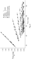
- Fig. 2 plots the two features T and dT/dt for the hottest pixel only.
- a temperature of 45 C is determined with a rate of change of temperature of 1.1 then it has been determined that under steady state conditions, with nothing else happening, the temperature will not develop into a critical temperature.
- a temperature of 65C has been measure with a rate of change of temperature of 1.75, even though the temperature at the moment is not critical, it has been established that under steady state conditions with no change, the temperature at this location will develop into a critical temperature and remedial action should be taken before that critical temperature develops.
- the different lines are shown in Fig. 2 to enable the different correlations for different scenarios to be viewed more easily.
- this classification method can be generalized to different types of devices, and different types of temperature sensors.
- the incorporation of the rise rate of the temperature enables the early prediction of a possible future overheating when it is combined with the temperature itself, as well as with the correlation of the measured T and dT/dt at the sensors position with the hotspot temperature.
Landscapes
- Physics & Mathematics (AREA)
- General Physics & Mathematics (AREA)
- Spectroscopy & Molecular Physics (AREA)
- Engineering & Computer Science (AREA)
- Power Engineering (AREA)
- Acoustics & Sound (AREA)
- Testing And Monitoring For Control Systems (AREA)
- Gas-Insulated Switchgears (AREA)
Claims (15)
- Ein Fehlererkennungssystem, umfassend:- einen Sensor;- eine Verarbeitungseinheit; und- eine Ausgabeeinheit,wobei der Sensor eingerichtet ist, Temperaturdaten an einer Sensorposition eines Geräts zu erfassen, wobei die Temperaturdaten erste Temperaturdaten und zweite Temperaturdaten umfassen, die nach einem ersten Zeitraum nach den ersten Temperaturdaten erfasst werden,wobei die Verarbeitungseinheit eingerichtet ist, eine Temperaturgröße zu bestimmen, die die Nutzung der ersten Temperaturdaten und/oder der zweiten Temperaturdaten umfasst,wobei die Verarbeitungseinheit eingerichtet ist, eine Temperaturänderungsrate zu bestimmen, die die Nutzung der ersten Temperaturdaten, der zweiten Temperaturdaten und des ersten Zeitraums umfasst,wobei die Verarbeitungseinheit eingerichtet ist, eine Temperatur an einem Ort des Geräts vorherzusagen, wobei die Temperaturgröße, die Temperaturänderungsrate und eine Korrelation genutzt werden, wobei die Korrelation eine Korrelation einer Vielzahl von Temperaturgrößen und einer Vielzahl von Temperaturänderungsraten an der Sensorposition mit einer Vielzahl von Hotspot-Temperaturen an dem Ort ist,wobei die Verarbeitungseinheit eingerichtet ist, zu bestimmen, ob das Gerät einen Fehler aufweist, indem die vorhergesagte Temperatur genutzt wird, undwobei die Ausgabeeinheit eingerichtet ist, eine Anzeige auszugeben, dass das Gerät einen Fehler aufweist, wenn festgestellt wird, dass das Gerät einen Fehler hat.
- System nach Anspruch 1, wobei die Verarbeitungseinheit eingerichtet ist, zu bestimmen, ob das Gerät einen Fehler aufweist, indem festgestellt wird, dass die vorhergesagte Temperatur einen Schwellenwert überschreitet.
- System nach einem der Ansprüche 1-2, wobei die Verarbeitungseinheit eingerichtet ist, die Korrelation aus einer Vielzahl von Korrelationen verschiedener Betriebsszenarien für das Gerät auszuwählen, wobei jede der Vielzahl von Korrelationen eine Korrelation einer Vielzahl von Temperaturgrößen und einer Vielzahl von Temperaturänderungsraten an der Sensorposition mit einer Vielzahl von Hotspot-Temperaturen an dem Ort ist.
- System nach Anspruch 3, wobei jede der Vielzahl von Korrelationen durch Experimente oder Simulationen bestimmt wird.
- System nach einem der Ansprüche 1-4, wobei das System mindestens einen weiteren Sensor umfasst, der eingerichtet ist, Strom und/oder Leistung zu messen, wobei Strom und/oder Leistung einen Strom durch das Gerät und/oder eine vom Gerät bezogene Leistung zu dem Zeitpunkt der Erfassung der ersten Temperaturdaten und/oder zu dem Zeitpunkt der Erfassung der zweiten Temperaturdaten umfassen, und wobei die Vorhersage der Temperatur an dem Ort die Nutzung des Stroms und/oder der Leistung umfasst.
- System nach Anspruch 5, abhängig von einem der Ansprüche 3-4, wobei die Auswahl der Korrelation die Nutzung des Stroms und/oder der Leistung umfasst.
- System nach einem der Ansprüche 1-6, wobei die Temperaturdaten dritte Temperaturdaten und vierte Temperaturdaten umfassen, die nach einem zweiten Zeitraum nach den dritten Temperaturdaten erfasst werden, wobei der zweite Zeitraum über einen anderen Zeitraum als der erste Zeitraum liegt, wobei die Verarbeitungseinheit eingerichtet ist, eine zweite Temperaturgröße zu bestimmen, die die Nutzung der dritten Temperaturdaten und/oder der vierten Temperaturdaten umfasst, wobei die Verarbeitungseinheit eingerichtet ist, eine zweite Temperaturänderungsrate zu bestimmen, die die Nutzung der dritten Temperaturdaten, der vierten Temperaturdaten und des zweiten Zeitraums umfasst, und wobei die Vorhersage der Temperatur an dem Ort die Nutzung der zweiten Temperaturgröße und der zweiten Temperaturänderungsrate umfasst.
- System nach Anspruch 7, abhängig von einem der Ansprüche 3-4 oder abhängig von einem der Ansprüche 5-6, abhängig von einem der Ansprüche 3-4, wobei die Auswahl der Korrelation die Nutzung der zweiten Temperaturgröße und der zweiten Temperaturänderungsrate umfasst.
- System nach einem der Ansprüche 1-8, wobei der Ort ein anderer Ort als die Sensorposition ist.
- System nach Anspruch 9, wobei der Ort thermisch mit der Sensorposition verbunden ist.
- System nach einem der Ansprüche 1-8, wobei der Ort die Sensorposition ist.
- System nach einem der Ansprüche 1-11, wobei der Sensor eine Infrarotkamera, ein Thermoelement, ein Oberflächenakustikwellen-Sensor oder ein RFID-Temperatursensor ist.
- System nach einem der Ansprüche 1-12, wobei das Gerät einen Teil einer Mittelspannungsschaltanlage oder einen Motor umfasst.
- Ein Fehlererkennungsverfahren, umfassend:Erfassen von Temperaturdaten mit einem Sensor an einer Sensorposition eines Geräts, wobei die Temperaturdaten erste Temperaturdaten und zweite Temperaturdaten umfassen, die nach einem ersten Zeitraum nach den ersten Temperaturdaten erfasst werden,Bestimmen einer Temperaturgröße durch eine Verarbeitungseinheit unter Verwendung der ersten Temperaturdaten und/oder der zweiten Temperaturdaten,Bestimmen einer Temperaturänderungsrate durch die Verarbeitungseinheit unter Verwendung der ersten Temperaturdaten, der zweiten Temperaturdaten und des ersten Zeitraums;Vorhersagen einer Temperatur an einem Ort des Geräts durch die Verarbeitungseinheit unter Verwendung der Temperaturgröße, der Temperaturänderungsrate und einer Korrelation, wobei die Korrelation eine Korrelation einer Vielzahl von Temperaturgrößen und einer Vielzahl von Temperaturänderungsraten an der Sensorposition mit einer Vielzahl von Hotspot-Temperaturen an dem Ort ist,Bestimmen, ob das Gerät einen Fehler aufweist, durch die Verarbeitungseinheit unter Nutzung der vorhergesagten Temperatur; undAusgeben einer Anzeige durch eine Ausgabeeinheit, dass das Gerät einen Fehler aufweist, wenn festgestellt wird, dass das Gerät einen Fehler hat.
- Verfahren nach Anspruch 14, wobei das Verfahren umfasst, dass die Verarbeitungseinheit die Korrelation aus einer Vielzahl von Korrelationen verschiedener Betriebsszenarien für das Gerät auswählt, wobei jede der Vielzahl von Korrelationen eine Korrelation einer Vielzahl von Temperaturgrößen und einer Vielzahl von Temperaturänderungsraten an der Sensorposition mit einer Vielzahl von Hotspot-Temperaturen an dem Ort ist.
Priority Applications (3)
| Application Number | Priority Date | Filing Date | Title |
|---|---|---|---|
| EP21168315.6A EP4075112B1 (de) | 2021-04-14 | 2021-04-14 | Fehlerdetektionssystem |
| CN202210368329.8A CN115267609B (zh) | 2021-04-14 | 2022-04-08 | 故障检测系统 |
| US17/720,756 US12034281B2 (en) | 2021-04-14 | 2022-04-14 | Fault detection system |
Applications Claiming Priority (1)
| Application Number | Priority Date | Filing Date | Title |
|---|---|---|---|
| EP21168315.6A EP4075112B1 (de) | 2021-04-14 | 2021-04-14 | Fehlerdetektionssystem |
Publications (3)
| Publication Number | Publication Date |
|---|---|
| EP4075112A1 EP4075112A1 (de) | 2022-10-19 |
| EP4075112C0 EP4075112C0 (de) | 2024-10-02 |
| EP4075112B1 true EP4075112B1 (de) | 2024-10-02 |
Family
ID=75529839
Family Applications (1)
| Application Number | Title | Priority Date | Filing Date |
|---|---|---|---|
| EP21168315.6A Active EP4075112B1 (de) | 2021-04-14 | 2021-04-14 | Fehlerdetektionssystem |
Country Status (3)
| Country | Link |
|---|---|
| US (1) | US12034281B2 (de) |
| EP (1) | EP4075112B1 (de) |
| CN (1) | CN115267609B (de) |
Cited By (1)
| Publication number | Priority date | Publication date | Assignee | Title |
|---|---|---|---|---|
| CN120725662A (zh) * | 2025-08-27 | 2025-09-30 | 国网浙江省电力有限公司杭州供电公司 | 一种基于高精度测温的电力设备故障检测方法和系统 |
Families Citing this family (4)
| Publication number | Priority date | Publication date | Assignee | Title |
|---|---|---|---|---|
| EP4414725A1 (de) * | 2023-02-10 | 2024-08-14 | Abb Schweiz Ag | System zur überwachung einer schaltanlage |
| CN117237590B (zh) * | 2023-11-10 | 2024-04-02 | 华能新能源股份有限公司山西分公司 | 基于图像识别的光伏组件热斑识别方法及系统 |
| CN117849503B (zh) * | 2024-01-02 | 2024-07-09 | 杨锡春 | 一种基于温度的变电柜故障检测方法及系统 |
| EP4624883A1 (de) * | 2024-03-25 | 2025-10-01 | Abb Schweiz Ag | Verfahren für ein elektrisches system |
Family Cites Families (21)
| Publication number | Priority date | Publication date | Assignee | Title |
|---|---|---|---|---|
| DE10020380A1 (de) * | 2000-04-26 | 2001-10-31 | Bodenseewerk Geraetetech | Verfahren und Vorrichtung zur Früherkennung einer möglichen Überhitzung eines Gegenstandes |
| US20050209813A1 (en) * | 2004-03-16 | 2005-09-22 | Johnson Controls Technology Company | Temperature sensing device |
| CN102788645B (zh) | 2012-07-18 | 2014-08-20 | 西安交通大学 | 电力设备电连接点温升红外监测系统及监测方法 |
| CN103226731A (zh) | 2013-03-20 | 2013-07-31 | 太原理工大学 | 一种热分布图像在线预测方法 |
| JP2016090756A (ja) * | 2014-10-31 | 2016-05-23 | 株式会社リコー | 検出装置、検出方法、加熱装置および画像形成装置 |
| JP5952438B1 (ja) * | 2015-01-22 | 2016-07-13 | ファナック株式会社 | 電動機の温度推定装置 |
| CN204461610U (zh) | 2015-02-11 | 2015-07-08 | 国家电网公司 | 电力高压隔离开关热故障的光纤红外无线远程报警装置 |
| CN204461613U (zh) | 2015-03-16 | 2015-07-08 | 国家电网公司 | 一种高压断路器热故障的光纤红外无线远程报警装置 |
| CN105869408B (zh) | 2016-04-27 | 2018-03-13 | 长安大学 | 一种轮毂温度异常检测与预警方法及系统 |
| CN106979820B (zh) | 2017-03-14 | 2019-02-19 | 西安电子科技大学 | 基于相似性度量因数的红外温升元件异常检测方法 |
| CN110800273B (zh) | 2017-04-24 | 2024-02-13 | 卡内基梅隆大学 | 虚拟传感器系统 |
| CN107289998B (zh) * | 2017-05-12 | 2019-08-23 | 淮阴工学院 | 基于can总线的猪舍环境温度智能监测系统 |
| US11113600B2 (en) | 2017-05-17 | 2021-09-07 | Bsquare Corp. | Translating sensor input into expertise |
| US11681344B2 (en) * | 2017-12-19 | 2023-06-20 | Harmonic, Inc. | Detecting imminent failure in a power supply |
| JP2019187089A (ja) * | 2018-04-10 | 2019-10-24 | 株式会社日立製作所 | 診断装置及び診断システム |
| CN109256747B (zh) | 2018-09-28 | 2020-03-17 | 国网福建省电力有限公司 | 一种电力高压柜内红外感温保护在线校准装置 |
| JP7154973B2 (ja) * | 2018-11-28 | 2022-10-18 | キヤノン株式会社 | レンズ装置、およびレンズ装置内のレンズの温度を推定する方法 |
| EP3671997B1 (de) * | 2018-12-20 | 2025-04-09 | ABB Schweiz AG | Überwachungssystem einer schaltanlage |
| CN109799852B (zh) * | 2019-01-15 | 2020-02-14 | 特斯联(北京)科技有限公司 | 一种基于机器学习的建筑温控设备优化控制方法和系统 |
| CN111121971B (zh) * | 2019-12-18 | 2021-09-03 | 广西电网有限责任公司电力科学研究院 | 一种通过高压开关柜表面温度变化判断故障类型的方法 |
| CN112415388A (zh) * | 2020-11-20 | 2021-02-26 | 珠海格力电器股份有限公司 | 电机故障的检测方法、装置、电子设备和暖通设备 |
-
2021
- 2021-04-14 EP EP21168315.6A patent/EP4075112B1/de active Active
-
2022
- 2022-04-08 CN CN202210368329.8A patent/CN115267609B/zh active Active
- 2022-04-14 US US17/720,756 patent/US12034281B2/en active Active
Cited By (1)
| Publication number | Priority date | Publication date | Assignee | Title |
|---|---|---|---|---|
| CN120725662A (zh) * | 2025-08-27 | 2025-09-30 | 国网浙江省电力有限公司杭州供电公司 | 一种基于高精度测温的电力设备故障检测方法和系统 |
Also Published As
| Publication number | Publication date |
|---|---|
| US20220337037A1 (en) | 2022-10-20 |
| CN115267609A (zh) | 2022-11-01 |
| US12034281B2 (en) | 2024-07-09 |
| EP4075112A1 (de) | 2022-10-19 |
| EP4075112C0 (de) | 2024-10-02 |
| CN115267609B (zh) | 2025-12-19 |
Similar Documents
| Publication | Publication Date | Title |
|---|---|---|
| EP4075112B1 (de) | Fehlerdetektionssystem | |
| KR100490601B1 (ko) | 이상검지방법 및 보호장치 | |
| US8942903B2 (en) | Method for predicting the temperature of a wheel bearing of a wheel of a vehicle | |
| Singh et al. | Infrared thermography based diagnosis of inter-turn fault and cooling system failure in three phase induction motor | |
| KR101962238B1 (ko) | 전자장비 내 이상 유무를 감지하는 센서 모니터링 시스템 | |
| CN120369129B (zh) | 一种换流阀内部温度监测预警方法及系统 | |
| CN112446854A (zh) | 用于监测开关设备的系统 | |
| CN112986711A (zh) | 监控电气设施的方法和系统 | |
| CN115219039B (zh) | 用于监控设备的系统 | |
| Land et al. | Design of a sensor to predict arcing faults in nuclear switchgear | |
| JP5820001B2 (ja) | Cpuの異常検出機能を備えた制御装置 | |
| CN120071535A (zh) | 一种基于物联网的消防电气预警方法及系统 | |
| KR20070078195A (ko) | 전력 케이블 접속부 열화 검출 시스템 및 열화 검출 방법 | |
| JP5024966B2 (ja) | 電子装置の障害監視装置、障害監視方法および障害監視プログラム | |
| EP3348978B1 (de) | Temperaturmessvorrichtung mit thermoelement | |
| US20050254548A1 (en) | Method and apparatus for monitoring a technical installation, especially for carrying out diagnosis | |
| EP3845987B1 (de) | System zur erkennung von temperaturanomalien, verfahren zur erkennung von temperaturanomalien und programm | |
| EP4120490B1 (de) | System zur überwachung einer vorrichtung | |
| KR101569145B1 (ko) | 전력설비 감시 장치 | |
| CN115628828B (zh) | 用于检测温升异常的方法和电子设备 | |
| KR102955896B1 (ko) | 딥러닝을 이용한 배전반의 이상동작 예측 방법 및 그 장치 | |
| JPH07123331B2 (ja) | 導電部過熱検出報知方法 | |
| KR20220112511A (ko) | 초음파를 이용한 전기설비 이상 감지 장치 및 방법 | |
| EP3502538B1 (de) | Verfahren zum betrieb eines sicherheitssystems für mittel- oder hochspannungsschaltanlage und solch ein sicherheitssystem selbst | |
| JP2674373B2 (ja) | 導電部過熱検出報知方法 |
Legal Events
| Date | Code | Title | Description |
|---|---|---|---|
| PUAI | Public reference made under article 153(3) epc to a published international application that has entered the european phase |
Free format text: ORIGINAL CODE: 0009012 |
|
| STAA | Information on the status of an ep patent application or granted ep patent |
Free format text: STATUS: THE APPLICATION HAS BEEN PUBLISHED |
|
| AK | Designated contracting states |
Kind code of ref document: A1 Designated state(s): AL AT BE BG CH CY CZ DE DK EE ES FI FR GB GR HR HU IE IS IT LI LT LU LV MC MK MT NL NO PL PT RO RS SE SI SK SM TR |
|
| STAA | Information on the status of an ep patent application or granted ep patent |
Free format text: STATUS: REQUEST FOR EXAMINATION WAS MADE |
|
| 17P | Request for examination filed |
Effective date: 20230418 |
|
| RBV | Designated contracting states (corrected) |
Designated state(s): AL AT BE BG CH CY CZ DE DK EE ES FI FR GB GR HR HU IE IS IT LI LT LU LV MC MK MT NL NO PL PT RO RS SE SI SK SM TR |
|
| GRAP | Despatch of communication of intention to grant a patent |
Free format text: ORIGINAL CODE: EPIDOSNIGR1 |
|
| STAA | Information on the status of an ep patent application or granted ep patent |
Free format text: STATUS: GRANT OF PATENT IS INTENDED |
|
| RIC1 | Information provided on ipc code assigned before grant |
Ipc: G01K 3/08 20060101ALI20240603BHEP Ipc: G01K 7/42 20060101AFI20240603BHEP |
|
| INTG | Intention to grant announced |
Effective date: 20240621 |
|
| GRAS | Grant fee paid |
Free format text: ORIGINAL CODE: EPIDOSNIGR3 |
|
| GRAA | (expected) grant |
Free format text: ORIGINAL CODE: 0009210 |
|
| STAA | Information on the status of an ep patent application or granted ep patent |
Free format text: STATUS: THE PATENT HAS BEEN GRANTED |
|
| RIN1 | Information on inventor provided before grant (corrected) |
Inventor name: PAPAGEORGIOU, ANASTASIOS Inventor name: KOZEL, TOMAS Inventor name: MRUCZEK, MACIEJ Inventor name: BECKER, OLIVER Inventor name: GEBHARDT, JOERG Inventor name: GITZEL, RALF Inventor name: HENCKEN, KAI Inventor name: OSTROWSKI, JOERG |
|
| AK | Designated contracting states |
Kind code of ref document: B1 Designated state(s): AL AT BE BG CH CY CZ DE DK EE ES FI FR GB GR HR HU IE IS IT LI LT LU LV MC MK MT NL NO PL PT RO RS SE SI SK SM TR |
|
| REG | Reference to a national code |
Ref country code: GB Ref legal event code: FG4D |
|
| REG | Reference to a national code |
Ref country code: CH Ref legal event code: EP |
|
| REG | Reference to a national code |
Ref country code: DE Ref legal event code: R096 Ref document number: 602021019498 Country of ref document: DE |
|
| REG | Reference to a national code |
Ref country code: IE Ref legal event code: FG4D |
|
| U01 | Request for unitary effect filed |
Effective date: 20241028 |
|
| U07 | Unitary effect registered |
Designated state(s): AT BE BG DE DK EE FI FR IT LT LU LV MT NL PT RO SE SI Effective date: 20241107 |
|
| PG25 | Lapsed in a contracting state [announced via postgrant information from national office to epo] |
Ref country code: IS Free format text: LAPSE BECAUSE OF FAILURE TO SUBMIT A TRANSLATION OF THE DESCRIPTION OR TO PAY THE FEE WITHIN THE PRESCRIBED TIME-LIMIT Effective date: 20250202 Ref country code: HR Free format text: LAPSE BECAUSE OF FAILURE TO SUBMIT A TRANSLATION OF THE DESCRIPTION OR TO PAY THE FEE WITHIN THE PRESCRIBED TIME-LIMIT Effective date: 20241002 |
|
| PG25 | Lapsed in a contracting state [announced via postgrant information from national office to epo] |
Ref country code: ES Free format text: LAPSE BECAUSE OF FAILURE TO SUBMIT A TRANSLATION OF THE DESCRIPTION OR TO PAY THE FEE WITHIN THE PRESCRIBED TIME-LIMIT Effective date: 20241002 |
|
| PG25 | Lapsed in a contracting state [announced via postgrant information from national office to epo] |
Ref country code: NO Free format text: LAPSE BECAUSE OF FAILURE TO SUBMIT A TRANSLATION OF THE DESCRIPTION OR TO PAY THE FEE WITHIN THE PRESCRIBED TIME-LIMIT Effective date: 20250102 |
|
| PG25 | Lapsed in a contracting state [announced via postgrant information from national office to epo] |
Ref country code: GR Free format text: LAPSE BECAUSE OF FAILURE TO SUBMIT A TRANSLATION OF THE DESCRIPTION OR TO PAY THE FEE WITHIN THE PRESCRIBED TIME-LIMIT Effective date: 20250103 |
|
| PG25 | Lapsed in a contracting state [announced via postgrant information from national office to epo] |
Ref country code: PL Free format text: LAPSE BECAUSE OF FAILURE TO SUBMIT A TRANSLATION OF THE DESCRIPTION OR TO PAY THE FEE WITHIN THE PRESCRIBED TIME-LIMIT Effective date: 20241002 Ref country code: CZ Free format text: LAPSE BECAUSE OF FAILURE TO SUBMIT A TRANSLATION OF THE DESCRIPTION OR TO PAY THE FEE WITHIN THE PRESCRIBED TIME-LIMIT Effective date: 20241002 |
|
| PG25 | Lapsed in a contracting state [announced via postgrant information from national office to epo] |
Ref country code: RS Free format text: LAPSE BECAUSE OF FAILURE TO SUBMIT A TRANSLATION OF THE DESCRIPTION OR TO PAY THE FEE WITHIN THE PRESCRIBED TIME-LIMIT Effective date: 20250102 |
|
| U20 | Renewal fee for the european patent with unitary effect paid |
Year of fee payment: 5 Effective date: 20250425 |
|
| PG25 | Lapsed in a contracting state [announced via postgrant information from national office to epo] |
Ref country code: SM Free format text: LAPSE BECAUSE OF FAILURE TO SUBMIT A TRANSLATION OF THE DESCRIPTION OR TO PAY THE FEE WITHIN THE PRESCRIBED TIME-LIMIT Effective date: 20241002 |
|
| PG25 | Lapsed in a contracting state [announced via postgrant information from national office to epo] |
Ref country code: SK Free format text: LAPSE BECAUSE OF FAILURE TO SUBMIT A TRANSLATION OF THE DESCRIPTION OR TO PAY THE FEE WITHIN THE PRESCRIBED TIME-LIMIT Effective date: 20241002 |
|
| PLBE | No opposition filed within time limit |
Free format text: ORIGINAL CODE: 0009261 |
|
| STAA | Information on the status of an ep patent application or granted ep patent |
Free format text: STATUS: NO OPPOSITION FILED WITHIN TIME LIMIT |
|
| 26N | No opposition filed |
Effective date: 20250703 |
|
| REG | Reference to a national code |
Ref country code: CH Ref legal event code: H13 Free format text: ST27 STATUS EVENT CODE: U-0-0-H10-H13 (AS PROVIDED BY THE NATIONAL OFFICE) Effective date: 20251125 |
|
| PG25 | Lapsed in a contracting state [announced via postgrant information from national office to epo] |
Ref country code: MC Free format text: LAPSE BECAUSE OF FAILURE TO SUBMIT A TRANSLATION OF THE DESCRIPTION OR TO PAY THE FEE WITHIN THE PRESCRIBED TIME-LIMIT Effective date: 20241002 |
|
| GBPC | Gb: european patent ceased through non-payment of renewal fee |
Effective date: 20250414 |
|
| PG25 | Lapsed in a contracting state [announced via postgrant information from national office to epo] |
Ref country code: GB Free format text: LAPSE BECAUSE OF NON-PAYMENT OF DUE FEES Effective date: 20250414 |
|
| PG25 | Lapsed in a contracting state [announced via postgrant information from national office to epo] |
Ref country code: CH Free format text: LAPSE BECAUSE OF NON-PAYMENT OF DUE FEES Effective date: 20250430 |
|
| PG25 | Lapsed in a contracting state [announced via postgrant information from national office to epo] |
Ref country code: IE Free format text: LAPSE BECAUSE OF NON-PAYMENT OF DUE FEES Effective date: 20250414 |