EP4075012B1 - Hydraulischer dämpfer mit kolbenanordnung mit abblaseventilen - Google Patents
Hydraulischer dämpfer mit kolbenanordnung mit abblaseventilen Download PDFInfo
- Publication number
- EP4075012B1 EP4075012B1 EP22167580.4A EP22167580A EP4075012B1 EP 4075012 B1 EP4075012 B1 EP 4075012B1 EP 22167580 A EP22167580 A EP 22167580A EP 4075012 B1 EP4075012 B1 EP 4075012B1
- Authority
- EP
- European Patent Office
- Prior art keywords
- valve
- disc
- piston assembly
- sleeve
- blow
- Prior art date
- Legal status (The legal status is an assumption and is not a legal conclusion. Google has not performed a legal analysis and makes no representation as to the accuracy of the status listed.)
- Active
Links
Images


Classifications
-
- F—MECHANICAL ENGINEERING; LIGHTING; HEATING; WEAPONS; BLASTING
- F16—ENGINEERING ELEMENTS AND UNITS; GENERAL MEASURES FOR PRODUCING AND MAINTAINING EFFECTIVE FUNCTIONING OF MACHINES OR INSTALLATIONS; THERMAL INSULATION IN GENERAL
- F16F—SPRINGS; SHOCK-ABSORBERS; MEANS FOR DAMPING VIBRATION
- F16F9/00—Springs, vibration-dampers, shock-absorbers, or similarly-constructed movement-dampers using a fluid or the equivalent as damping medium
- F16F9/32—Details
- F16F9/50—Special means providing automatic damping adjustment, i.e. self-adjustment of damping by particular sliding movements of a valve element, other than flexions or displacement of valve discs; Special means providing self-adjustment of spring characteristics
- F16F9/512—Means responsive to load action, i.e. static load on the damper or dynamic fluid pressure changes in the damper, e.g. due to changes in velocity
-
- F—MECHANICAL ENGINEERING; LIGHTING; HEATING; WEAPONS; BLASTING
- F16—ENGINEERING ELEMENTS AND UNITS; GENERAL MEASURES FOR PRODUCING AND MAINTAINING EFFECTIVE FUNCTIONING OF MACHINES OR INSTALLATIONS; THERMAL INSULATION IN GENERAL
- F16F—SPRINGS; SHOCK-ABSORBERS; MEANS FOR DAMPING VIBRATION
- F16F9/00—Springs, vibration-dampers, shock-absorbers, or similarly-constructed movement-dampers using a fluid or the equivalent as damping medium
- F16F9/32—Details
- F16F9/34—Special valve constructions; Shape or construction of throttling passages
- F16F9/348—Throttling passages in the form of annular discs or other plate-like elements which may or may not have a spring action, operating in opposite directions or singly, e.g. annular discs positioned on top of the valve or piston body
- F16F9/3482—Throttling passages in the form of annular discs or other plate-like elements which may or may not have a spring action, operating in opposite directions or singly, e.g. annular discs positioned on top of the valve or piston body the annular discs being incorporated within the valve or piston body
Definitions
- the invention relates to a hydraulic damper, in particular a motor vehicle hydraulic suspension damper, comprising: a tube filled with working liquid; a piston assembly disposed slidably inside the tube, dividing the tube into a rebound chamber and a compression chamber, the piston assembly including a rebound valve assembly and a compression valve assembly to control the flow of working liquid passing between the rebound chamber and the compression chamber, wherein each valve assembly comprises a deflectable-disc valve and a blow-off valve; and a piston rod attached to the piston assembly and extending outside the tube through a sealed piston rod guide.
- a piston assembly is a key component of a hydraulic damper and its construction and configuration has a major influence on a damper force vs. piston velocity characteristic during the damper compression and rebound stroke. It is therefore desirable to enable for shaping and tuning this force-velocity relation for each piston velocity range (low speed, medium speed, high speed) independently for each range and independently for the compression and for the rebound stroke, in order to improve safety and vehicle handling properties, reduce unwanted vibrations, improve passengers comfort, etc.
- deflectable-disc valves In deflectable-disc valves, a plurality of deflectable discs with predefined geometry and thickness are used to tune the damping characteristic in all piston velocity ranges.
- a deflectable or displaceable closing element In a blow-off valve, a deflectable or displaceable closing element, usually in a form of a flat disc, is biased by a spring to keep the flow passages closed. After a certain pressure threshold is reached, the closing element compresses the spring, opening the flow passages.
- Various spring preloads are used to adjust damping characteristics of such a valve.
- the main advantage of a blow-off valve is its flat and digressive characteristic, so that driving a vehicle over curbs is smother.
- Dampers having piston assemblies provided both with deflectable-disc type valves and blow-off valves are known e.g. from patent publications GB2314602 , WO2005026572 , US2002096408 , KR20130139491 , US5823306 or US2011031077 .
- a damper of the kind mentioned in the outset, according to the present invention is characterised in that the piston assembly is provided with an internal chamber and comprises two sleeve-shaped members closing each side of said internal chamber, wherein each sleeve-shaped member is provided with a number blow-off valve flow passages, which are radially proximal, a plurality of deflectable-disc valve flow passages, which are radially distal, and a central opening, wherein the piston rod passes through said central openings in said sleeve-shaped members to secure the piston assembly, a plurality of deflectable disc(s) of the deflectable-disc valve cover(s) said radially distal flow passages of each sleeve-shaped member at its external side, wherein said deflectable disc(s) is/are provided with a plurality of radially proximal flow passages corresponding to said radially proximal flow passages of said sleeve-shaped member, and is/are axially fixed at the
- said sleeve-shaped members each include a cylindrical section that extends annularly around said internal chamber of the piston assembly, and wherein said piston assembly further includes an annular seal configured to seal between the cylindrical sections and the tube.
- the piston assembly further comprises a body defining said internal chamber of the piston assembly and is provided with an annular seal configured to seal against the tube.
- said at least one disc of the blow-off valve is deflectable or displaceable.
- said piston assembly further comprises at least one internal flange and said at least one spring disposed within said internal chamber is compressed between said internal flange and one of said spring seats and biases this seat towards said at least one number of disc.
- the piston assembly further comprises at least one insert disposed within said internal chamber and provided with said radially internal flange.
- the piston assembly further comprises at least one second spring disposed within said internal chamber and compressed between said internal flange and one of said spring seats, and biases this seat towards said number of disc(s).
- said internal chamber is cylindrical.
- said rebound valve assemblies and said compression valve assemblies are made of identical parts.
- said flow channel is defined by a plurality of radially external notches of at least one disc of the blow-off valve.
- said flow channel is defined by a space separating the at least one disc and said radially proximal flow passages of the blow-off valve.
- the piston assembly further comprises an internal sleeve disposed within said internal chamber abutting an internal wall of each of said cylindrical sections and covering said annular gap.
- said annular seal includes a narrowed section defining an annular chamber between said annular seal and the main tube, said annular seal defining a plurality of radial openings that fluidly join said internal chamber of the piston assembly with said annular chamber to balance hydraulic pressure therebetween.
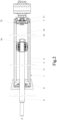
- Fig. 1 schematically illustrates a fragment of an exemplary vehicle suspension comprising a damper 1 of the present invention attached to a vehicle chassis 101 by means of a top mount 102 and a plurality of screws 103 disposed on the periphery of the upper surface of the top mount 102.
- the top mount 102 is connected to a coil spring 104 and a piston rod 5 of the damper 1.
- the external tube 2 of the damper 1 is connected to the steering knuckle 105 supporting the vehicle wheel 106.
- Fig. 2 presents an embodiment of a twin-tube damper 1 according to the present invention that may be employed in a typical motor vehicle suspension.
- the damper 1 comprises an external tube 2 and a main tube 3 filled with viscous working liquid inside of which a piston assembly 4a is attached to a piston rod 5.
- the piston rod 5 extends outside the main tube 3 through a sealed piston rod guide 6 is movably disposed along an axis A.
- the damper 1 is also provided with a base valve assembly 7 fixed at the other end of the main tube 3.
- the piston assembly 4a makes a sliding fit with the inner surface of the main tube 3 and divides the tube 3 into a rebound chamber 11 (between the piston rod guide 6 and the piston assembly 4a) and a compression chamber 12 (between the piston assembly 4a and the base valve assembly 7).
- An additional compensation chamber 13 is located at the other side of the base valve assembly 7.
- the base valve assembly 7 is provided with compression 71 and rebound 72 valve assemblies to control the flow of working liquid passing between the compression chamber 12 and the compensation chamber 13 while the piston assembly 4a is in motion. Nonetheless, as shall be recognised by those skilled in the art from the following description, the invention is also applicable other damper constructions, including mono-tube dampers provided with a gas compensation chamber separated with a slidable diaphragm from the compression chamber 12.
- compression refers to these elements or parts of elements which are adjacent to or face the compression chamber 12 or, in a case of working liquid flow direction, it refers to this flow direction that takes place during the compression stroke of the damper.
- rebound refers to these elements or these parts of particular elements which are adjacent to or face the rebound chamber 11 or, in a case of working liquid flow direction, it refers to this flow direction that takes place during the rebound stroke of the damper.
- the piston assembly according to the present invention is provided with compression valve assemblies 41c, 42c and rebound valve assemblies 41r, 42r to control the flow of working liquid passing between the rebound chamber 11 and the compression chamber 12 while the piston assembly 4a is in motion.
- Each valve assembly 41, 42 includes a deflectable-disc valve 41 and a blow-off valve 42.
- the embodiment of the piston assembly 4a is symmetric with respect to the plane perpendicular to the axis A; compression valve assemblies 41c, 42c are mirror images of the rebound valve assemblies 41r, 42r and are made of the same components. This significantly simplifies the construction of the piston assembly 4a.
- the piston assembly 4a comprises two sleeve-shaped members 44a provided with central openings 443.
- a narrowed section 51 of the piston rod 5 passes through these openings 443 and a nut 52 is screwed on a threaded end of this narrowed section 51 securing the piston assembly 4a tightly to the piston rod 5.
- Each sleeve-shaped member 44a has a cylindrical section 444 and the cylindrical sections 444 of both sleeve-shaped members 44a face each other with a certain annular gap 447 (cf. Figs. 9, 10 ) in between.
- a sleeve 46 adjoining the narrowed section 51 of the piston rod 5 provides support for the sleeve-shaped members 44a.
- An annular seal 45 is disposed radially outside of the sleeve-shaped member 44a and disposed within two adjoining annular groves 445 formed in the cylindrical sections 444, closing this annular gap and sealing against the main tube 3 with a sliding fit.
- Sleeve-shaped members 44a and the sleeve 46 of the piston rod 5 define an internal, substantially cylindrical chamber 43.
- Each sleeve-shaped member 44a is provided with a plurality of blow-off valve flow passages 442 spaced at equal angular intervals, which are radially proximal, and a plurality of deflectable-disc valve flow passages 441 spaced at equal angular intervals, and which are radially distal.
- the deflectable-disc valve 41 comprises a deflectable disc 411 that covers the radially distal flow passages 441 at the external side of the sleeve-shaped member 44a and is provided with a plurality of radially proximal flow passages 4111 corresponding to the blow-off valve flow passages 442 of the sleeve-shaped member 44a.
- the deflectable disc 411 is axially fixed at the narrowed section 51 of the piston rod 5 by means of a spacer 412 and a retainer 413.
- the blow-off valve 42 comprises stack of discs formed by a spacer 421 adjoining the sleeve-shaped member 44a at its internal side, followed by a notched disc 422 provided with a plurality of radially external notches 4221 spaced at equal angular intervals, three discs 423 and a spacer 424.
- radially internal sides of the stacks of discs 422, 423 are clamped by the sleeve 46 to the sleeve-shaped members 44a.
- Each blow-off valve 42 further comprises a spring seat 425, also slidably disposed about the sleeve 46, which abuts the axially internal disc 423.
- a spring 47a disposed within the internal chamber 43 biases the spring seats 425 towards the discs 423 and 422 to cover the blow-off valve flow passages 442 in the sleeve-shaped member 44a.
- the working liquid flows into the chamber 43 through radially proximal flow passages 4111 of the disc 411, blow-off valve flow passages 442 of the sleeve-shaped member 44a, and through a flow channel defined by the external notches 4221 in the notched disc 422 inside the chamber 43.
- the working liquid Flowing out of the chamber 43 the working liquid enters into the deflectable-disc valve flow passages 441 of the sleeve-shaped member 44a on the opposite side of the chamber 43 and forces the disc 411 of the deflectable-disc valve 41 outside the chamber to deflect creating an annular gap restricting the flow and having the width increasing along with the pressure of the working liquid, until the point when the disc 411 abuts the retainer 413 and its further deflection is impossible.
- FIG. 4 and 6 Another embodiment of a piston assembly 4b is shown in Figs. 4 and 6 .
- This embodiment is also symmetric, similarly as in the embodiment of the piston assembly 4a, and the compression valve assemblies 41c, 42c are mirror images of the rebound valve assemblies 41r, 42r and are made of the same components.
- the piston assembly 4b comprises a piston body 48 defining a cylindrical chamber 43.
- the piston body 48 is provided with an annular grove 481 in which an external annular seal 45 is disposed to seal against the main tube 3 with a sliding fit.
- the piston assembly 4b comprises two sleeve-shaped members 44b of a construction similar to sleeve-shaped members 44a of the piston assembly 4a.
- a narrowed section 51 of the piston rod 5 passes through central openings 443 of the sleeve-shaped members 44b and a nut 52 is screwed on a threaded end of this narrowed section 51 securing the piston assembly 4b to the piston rod 5.
- Each sleeve-shaped member 44b is disposed in an annular recess 482 provided in the piston body 48 at the end of the cylindrical chamber 43 and this connection is sealed with an annular o-ring seal 446.
- the deflectable disc valve 41 has the construction similar to the one discussed above with regard to the piston assembly 4a.
- the blow-off valve 42 comprises a spacer 421 adjoining the sleeve-shaped member 44b at its internal side, followed by a deflectable disc 423 and a spring seat 425 disposed slidably about the narrowed section 51 of the piston rod 5 and abutting the disc 423.
- Spring seats 425 comprise cylindrical sections 4251 providing guidance for the spring 47b.
- the piston assembly 4b operation is similar to the operation of the piston assembly 4a discussed above. In this embodiment, however, the working liquid flows into the chamber 43 through radially proximal flow passages 4111 of the disc 411, blow-off valve flow passages 442 of the sleeve-shaped member 44b, and through a flow channel 426 defined by the spacer 421 between the blow-off valve flow passages 442 and the disc 423.
- piston assembly 4d comprises a piston body 48 defining a cylindrical chamber 43 which is closed at the compression and at the rebound side with sleeve-shaped members 44b.
- the piston assembly 4d comprises an insert 49 disposed within an annular recess 482r of the piston assembly 4d at the rebound side of the cylindrical chamber 43 and at the rebound side of the cylindrical chamber 43 the sleeve-shaped member 44b is disposed within an annular recess 492r provided in the insert 49.
- the insert 49 has a radially internal flange 491 within the cylindrical chamber 43 that provides an abutment surface for an additional second spring 47d biasing a spring seat 425 of the rebound blow-off valve 42r along with a main spring 47b which is compressed between the spring seats 425 of the blow-off valves 42c and 42r.
- another embodiment of the piston assembly could be provided with two inserts 49 or without insert but with an internal flange by the piston assembly 4 itself (cf. Fig. 8 ).
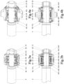
- Figs. 7a and 7b illustrates the functionality of the piston assembly 4d during the compression stroke.
- the working liquid flows via pathway C1 from the compression chamber 12 to the rebound chamber 11 through flow passages 4111 in the deflectable-disc 411, through blow-off valve flow passages 442 of the sleeve-shaped member 44b, through an annular gap between the blow-off valve disc 423 and the rebound side of the blow-off valve flow passages 442; through the cylindrical chamber 43; through the deflectable-disc valve flow passages 441 of the sleeve-shaped member 44b and its pressure forces the deflectable-disc 411 of the compression deflectable-disc valve 41c to deflect.
- a predefined velocity threshold as shown in Fig.
- the working liquid flows via pathway R1 from the rebound chamber 11 to the compression chamber 12 through flow passages 4111 in the deflectable-disc 411, through blow-off valve flow passages 442 of the sleeve-shaped member 44b, through an annular gap between the blow-off valve disc 423 and the compression side of the blow-off valve flow passages 442; through the cylindrical chamber 43; through the deflectable-disc valve flow passages 441 of the sleeve-shaped member 44b and its pressure forces the deflectable-disc 411 of the rebound deflectable-disc valve 41r to deflect. Above a predefined velocity threshold, as shown in Fig.
- FIG. 8 Yet another embodiment of a piston assembly 4e, shown in Fig. 8 , has a construction similar to the piston assemblies 4b and 4d, wherein a piston body 48 is provided in a chamber 43 with a radially internal flange 483. A spring 47e is compressed between this internal flange 483 and a spring seat 425 of a rebound blow-off valve 42r. Another spring 47f is compressed between this internal flange 483 and a spring seat 425 of a compression blow-off valve 42c.
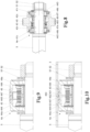
- annular gap 447 present between facing each other cylindrical sections 444 of both sleeve-shaped members 44a creates an opportunity for the working liquid to flow through this gap 447 and act with its pressure on an external annular seal 45 of the piston assembly 4a, leading to disadvantageous increase of friction.
- a sealing arrangement is provided in a form of a thin-walled internal sleeve 448 disposed within an internal chamber 43.
- the internal sleeve 448 abuts the internal wall of the cylindrical sections 444 of the sleeve-shaped members 44a and with a certain axial clearance covers the annular gap 447.
- FIG. 10 Another form of a sealing arrangement is shown in Fig. 10 .
- an annular seal 45 is provided with a narrowed section 451 in the middle defining an annular chamber 453 between the sealing 45 and the main tube 3.
- This narrowed section 451 is provided with a plurality of radial openings 452 spaced at equal angular intervals and which fluidly join an internal chamber 43 of the piston assembly 4a with the annular chamber 453 and balance hydraulic pressure therebetween.
Landscapes
- Engineering & Computer Science (AREA)
- General Engineering & Computer Science (AREA)
- Mechanical Engineering (AREA)
- Physics & Mathematics (AREA)
- Fluid Mechanics (AREA)
- Fluid-Damping Devices (AREA)
Claims (13)
- Ein hydraulischer Dämpfer (1), insbesondere ein hydraulischer Aufhängungsdämpfer für Kraftfahrzeuge, der aus Folgendem besteht:einem mit Arbeitsflüssigkeit gefüllten Rohr (3);einer Kolbenbaugruppe (4), die gleitend im inneren des Rohrs (3) angeordnet ist und das Rohr (3) in eine Rückstoßkammer (11) und eine Druckkammer (12) unterteilt, dadurch gekennzeichnet, dass die Kolbenbaugruppe zwei hülsenförmige Elemente (44), eine Rückstoßventilbaugruppe (41r, 42r) und eine Druckventilbaugruppe (41c, 42c) umfasst, wobei sowohl die Rückstoßventilbaugruppe (41r, 42r) als auch die Druckventilbaugruppe (41c, 42c) ein ablenkbares Scheibenventil (41) und ein Abblaseventil (42) umfasst;einer inneren Kammer (43), die sich zwischen den beiden hülsenförmigen Elementen (44) erstreckt;einer Kolbenstange (5), die an der Kolbenbaugruppe (4) befestigt ist und durch eine abgedichtete Kolbenstangenführung (6) aus dem Rohr (3) herausragt;wobei jedes der hülsenförmigen Elemente (44) eine Vielzahl von Strömungsdurchgängen der Abblaseventile (442), die radial proximal sind, eine Vielzahl von Strömungsdurchgängen der ablenkbaren Scheibenventile (441), die radial distal sind, und eine zentrale Öffnung (443) definiert,wobei die Kolbenstange (5) durch die zentralen Öffnungen (443) in jedem der hülsenförmigen Elemente (44) verläuft;wobei jedes der ablenkbaren Scheibenventile (41) mindestens eine ablenkbare Scheibe (411) enthält, die ein äußeres Ende der Strömungsdurchgänge der ablenkbaren Scheibenventile (441) eines entsprechenden der hülsenförmigen Elemente (44) abdeckt;wobei jede der mindestens einen ablenkbaren Scheibe (411) axial an der Kolbenstange befestigt ist und eine Vielzahl von radial nahen Strömungsdurchgängen (4111) definiert, die den Strömungsdurchgängen der Abblaseventile (442) eines entsprechenden der hülsenförmigen Elemente (44) entsprechen; jedes der Abblaseventile (42) mindestens eine Scheibe (422, 423) aufweist, die an ein inneres Ende der Strömungsdurchgänge der Abblaseventile (442) eines entsprechenden der hülsenförmigen Elemente (44) angrenzt;wobei ein Strömungskanal (4221, 426) die innere Kammer (43) mit den Strömungsdurchgängen der Abblaseventile (442) jedes hülsenförmigen Elements (44) flüssigkeitsmäßig verbindet; undwobei die Kolbenbaugruppe (4) ferner einen Federsitz (425), der an der mindestens einen Scheibe (422, 423) jedes der Abblaseventile (42) anliegt, und mindestens eine Feder (47) umfasst, die in der inneren Kammer (43) angeordnet und so konfiguriert ist, dass sie die Federsitze (425) in Richtung der mindestens einen Scheibe (422, 423) vorspannt.
- Der hydraulische Dämpfer nach Anspruch 1, wobei die hülsenförmigen Elemente (44) jeweils einen zylindrischen Abschnitt (444) umfassen, der sich ringförmig um die innere Kammer (43) der Kolbenbaugruppe (4a) erstreckt, und wobei die Kolbenbaugruppe (4) ferner eine ringförmige Dichtung (45) umfasst, die so konfiguriert ist, dass sie zwischen den zylindrischen Abschnitten (444) und dem Rohr abdichtet.
- Der hydraulische Dämpfer nach Anspruch 1, wobei die Kolbenbaugruppe (4b, 4d, 4e) weiterhin einen Körper (48) umfasst, der die innere Kammer (43) der Kolbenbaugruppe (4b, 4d, 4e) definiert und mit einer ringförmigen Dichtung (45) versehen ist, die so konfiguriert ist, dass sie gegen das Rohr abdichtet.
- Der hydraulische Dämpfer nach einem der Ansprüche 1 bis 3, wobei die mindestens eine Scheibe (422, 423) des Abblaseventils (42) auslenkbar oder verschiebbar ist.
- Der hydraulische Dämpfer nach einem der Ansprüche 1 bis 4, wobei die Kolbenbaugruppe (4d, 4e) weiterhin mindestens einen Innenflansch (483, 491) aufweist und die mindestens eine in der inneren Kammer (23) angeordnete Feder (47e, 47f) zwischen dem Innenflansch (483, 491) und einem der Federsitze (425) zusammengedrückt wird und den einen der Federsitze (425) in Richtung der mindestens einen Scheibe (422, 423) vorspannt.
- Der hydraulische Dämpfer nach Anspruch 5, wobei die Kolbenbaugruppe (4d) weiterhin mindestens einen Einsatz (49) umfasst, der in der inneren Kammer (43) angeordnet ist und den mindestens einen Innenflansch (491) enthält.
- Der hydraulische Dämpfer nach Anspruch 5 oder 6, wobei die Kolbenbaugruppe (4d) weiterhin mindestens eine zweite Feder (47d) umfasst, die in der inneren Kammer (43) angeordnet ist und zwischen dem Innenflansch (483, 491) und einem der Federsitze (425) zusammengedrückt wird und den einen der Federsitze (425) gegen die mindestens eine Scheibe (422, 423) vorspannt.
- Der hydraulische Dämpfer nach einem der Ansprüche 1 bis 7, wobei die innere Kammer (43) zylindrisch ist.
- Der hydraulische Dämpfer nach einem der Ansprüche 1 bis 8, wobei die Rückstoßventilbaugruppe (41r, 42r) und die Druckventilbaugruppe (41c, 42c) aus identischen Teilen hergestellt sind.
- Der hydraulische Dämpfer nach einem der Ansprüche 1 bis 9, wobei der Strömungskanal durch eine Vielzahl von radial äußeren Kerben (4221) der mindestens einen Scheibe (422, 423) des Abblaseventils (42) definiert ist.
- Der hydraulische Dämpfer nach einem der Ansprüche 1 bis 10, wobei der Strömungskanal durch einen Raum definiert ist, der die mindestens eine Scheibe (422, 423) und die Strömungsdurchgänge der Abblaseventile (442) des Abblaseventils (42) trennt.
- Der hydraulische Dämpfer nach einem der Ansprüche 2 bis 11, wobei die zylindrischen Abschnitte (444) der hülsenförmigen Elemente (44a) einen ringförmigen Spalt (447) dazwischen definieren und die Kolbenbaugruppe (4a) ferner eine innere Hülse (448) umfasst, die innerhalb der inneren Kammer (43) angeordnet ist und an eine innere Wand jedes der zylindrischen Abschnitte (444) anstößt und den ringförmigen Spalt (447) abdeckt.
- Der hydraulische Dämpfer nach einem der Ansprüche 2 bis 11, wobei die zylindrischen Abschnitte (444) der hülsenförmigen Elemente (44a) einen ringförmigen Spalt (447) dazwischen definieren, und die ringförmige Dichtung (45) einen verengten Abschnitt (451) umfasst, der eine ringförmige Kammer (453) zwischen der ringförmigen Dichtung (45) und dem Rohr (3) definiert, wobei die ringförmige Dichtung (45) eine Vielzahl von radialen Öffnungen (452) definiert, die die innere Kammer (43) der Kolbenbaugruppe (4a) mit der ringförmigen Kammer (453) verbinden, um den hydraulischen Druck dazwischen auszugleichen.
Applications Claiming Priority (2)
| Application Number | Priority Date | Filing Date | Title |
|---|---|---|---|
| CN202110388034.2A CN113074206B (zh) | 2021-04-12 | 2021-04-12 | 液压阻尼器 |
| US17/670,456 US11898620B2 (en) | 2021-04-12 | 2022-02-12 | Hydraulic damper with piston assembly having blow-off valves |
Publications (2)
| Publication Number | Publication Date |
|---|---|
| EP4075012A1 EP4075012A1 (de) | 2022-10-19 |
| EP4075012B1 true EP4075012B1 (de) | 2025-01-22 |
Family
ID=81306888
Family Applications (1)
| Application Number | Title | Priority Date | Filing Date |
|---|---|---|---|
| EP22167580.4A Active EP4075012B1 (de) | 2021-04-12 | 2022-04-11 | Hydraulischer dämpfer mit kolbenanordnung mit abblaseventilen |
Country Status (3)
| Country | Link |
|---|---|
| EP (1) | EP4075012B1 (de) |
| ES (1) | ES3020059T3 (de) |
| PL (1) | PL4075012T3 (de) |
Family Cites Families (9)
| Publication number | Priority date | Publication date | Assignee | Title |
|---|---|---|---|---|
| GB2314602B (en) | 1996-06-28 | 2000-09-20 | Delphi Espana Automotive Sys | Suspension strut |
| US5823306A (en) | 1996-11-12 | 1998-10-20 | Tenneco Automotive Inc. | Stroke dependent damping |
| US6655512B2 (en) | 2000-12-19 | 2003-12-02 | Delphi Technologies, Inc. | Variable area low speed orifice in a vehicle damper |
| US7097016B2 (en) | 2003-09-05 | 2006-08-29 | Tenneco Automotive Operating Company Inc. | Fulcrum blow off valve for use in a shock absorber |
| DE102005040283A1 (de) * | 2005-08-24 | 2007-03-08 | Zf Friedrichshafen Ag | Schwingungsdämpfer |
| EP2233775B1 (de) | 2009-03-23 | 2012-02-08 | BWI Company Limited S.A. | Hydraulischer Radaufhängungsdämpfer |
| KR101374877B1 (ko) | 2012-06-13 | 2014-03-18 | 주식회사 만도 | 쇽업소버의 피스톤 어셈블리 |
| NL2010038C2 (en) * | 2012-12-21 | 2014-06-24 | Koni Bv | Shock absorber. |
| KR20180083721A (ko) * | 2017-01-13 | 2018-07-23 | 주식회사 만도 | 쇽업소버의 밸브구조 |
-
2022
- 2022-04-11 EP EP22167580.4A patent/EP4075012B1/de active Active
- 2022-04-11 ES ES22167580T patent/ES3020059T3/es active Active
- 2022-04-11 PL PL22167580.4T patent/PL4075012T3/pl unknown
Also Published As
| Publication number | Publication date |
|---|---|
| PL4075012T3 (pl) | 2025-04-22 |
| ES3020059T3 (en) | 2025-05-21 |
| EP4075012A1 (de) | 2022-10-19 |
Similar Documents
| Publication | Publication Date | Title |
|---|---|---|
| US10393211B2 (en) | Hydraulic damper with a hydraulic stop arrangement | |
| US12320404B2 (en) | Damper assembly | |
| US8919505B2 (en) | Hydraulic suspension damper | |
| EP2841792B1 (de) | Hydraulischer aufhängungsdämpfer mit schwimmertellerventil | |
| US11686367B2 (en) | Hydraulic damper and a piston for the hydraulic damper assembly | |
| US11732771B2 (en) | Hydraulic damper assembly and a piston for a hydraulic damper assembly | |
| US11898620B2 (en) | Hydraulic damper with piston assembly having blow-off valves | |
| US12416344B2 (en) | Hydraulic damper with a hydromechanical compression stop assembly | |
| US12410847B2 (en) | Shock absorber | |
| JP7470076B2 (ja) | バルブおよび緩衝器 | |
| US12435771B2 (en) | Shock absorber | |
| EP4075012B1 (de) | Hydraulischer dämpfer mit kolbenanordnung mit abblaseventilen | |
| US10239376B2 (en) | Hydraulic damper with an x-flow piston assembly | |
| CN114738422B (zh) | 阻尼器组件及用于阻尼器组件的活塞 | |
| GB2314602A (en) | A damper having a piston valve with blow-off characteristic | |
| EP3992493A2 (de) | Hydraulische dämpferanordnung und kolben für eine hydraulische dämpferanordnung | |
| EP4163514B1 (de) | Hydraulischer dämpfer mit einer hydromechanischen druckanschlaganordnung | |
| US20250297664A1 (en) | Damper assembly and piston therefor | |
| WO2025258135A1 (ja) | 緩衝器 | |
| CN117072609A (zh) | 阻尼器组件及用于阻尼器的液压压缩止动组件 |
Legal Events
| Date | Code | Title | Description |
|---|---|---|---|
| PUAI | Public reference made under article 153(3) epc to a published international application that has entered the european phase |
Free format text: ORIGINAL CODE: 0009012 |
|
| STAA | Information on the status of an ep patent application or granted ep patent |
Free format text: STATUS: THE APPLICATION HAS BEEN PUBLISHED |
|
| AK | Designated contracting states |
Kind code of ref document: A1 Designated state(s): AL AT BE BG CH CY CZ DE DK EE ES FI FR GB GR HR HU IE IS IT LI LT LU LV MC MK MT NL NO PL PT RO RS SE SI SK SM TR |
|
| STAA | Information on the status of an ep patent application or granted ep patent |
Free format text: STATUS: REQUEST FOR EXAMINATION WAS MADE |
|
| 17P | Request for examination filed |
Effective date: 20230421 |
|
| RBV | Designated contracting states (corrected) |
Designated state(s): AL AT BE BG CH CY CZ DE DK EE ES FI FR GB GR HR HU IE IS IT LI LT LU LV MC MK MT NL NO PL PT RO RS SE SI SK SM TR |
|
| GRAP | Despatch of communication of intention to grant a patent |
Free format text: ORIGINAL CODE: EPIDOSNIGR1 |
|
| STAA | Information on the status of an ep patent application or granted ep patent |
Free format text: STATUS: GRANT OF PATENT IS INTENDED |
|
| INTG | Intention to grant announced |
Effective date: 20240820 |
|
| GRAS | Grant fee paid |
Free format text: ORIGINAL CODE: EPIDOSNIGR3 |
|
| GRAA | (expected) grant |
Free format text: ORIGINAL CODE: 0009210 |
|
| STAA | Information on the status of an ep patent application or granted ep patent |
Free format text: STATUS: THE PATENT HAS BEEN GRANTED |
|
| AK | Designated contracting states |
Kind code of ref document: B1 Designated state(s): AL AT BE BG CH CY CZ DE DK EE ES FI FR GB GR HR HU IE IS IT LI LT LU LV MC MK MT NL NO PL PT RO RS SE SI SK SM TR |
|
| REG | Reference to a national code |
Ref country code: GB Ref legal event code: FG4D |
|
| REG | Reference to a national code |
Ref country code: CH Ref legal event code: EP |
|
| REG | Reference to a national code |
Ref country code: IE Ref legal event code: FG4D |
|
| REG | Reference to a national code |
Ref country code: DE Ref legal event code: R096 Ref document number: 602022009706 Country of ref document: DE |
|
| P01 | Opt-out of the competence of the unified patent court (upc) registered |
Free format text: CASE NUMBER: APP_13137/2025 Effective date: 20250317 |
|
| REG | Reference to a national code |
Ref country code: ES Ref legal event code: FG2A Ref document number: 3020059 Country of ref document: ES Kind code of ref document: T3 Effective date: 20250521 |
|
| REG | Reference to a national code |
Ref country code: NL Ref legal event code: MP Effective date: 20250122 |
|
| PG25 | Lapsed in a contracting state [announced via postgrant information from national office to epo] |
Ref country code: NL Free format text: LAPSE BECAUSE OF FAILURE TO SUBMIT A TRANSLATION OF THE DESCRIPTION OR TO PAY THE FEE WITHIN THE PRESCRIBED TIME-LIMIT Effective date: 20250122 |
|
| PG25 | Lapsed in a contracting state [announced via postgrant information from national office to epo] |
Ref country code: RS Free format text: LAPSE BECAUSE OF FAILURE TO SUBMIT A TRANSLATION OF THE DESCRIPTION OR TO PAY THE FEE WITHIN THE PRESCRIBED TIME-LIMIT Effective date: 20250422 |
|
| PG25 | Lapsed in a contracting state [announced via postgrant information from national office to epo] |
Ref country code: FI Free format text: LAPSE BECAUSE OF FAILURE TO SUBMIT A TRANSLATION OF THE DESCRIPTION OR TO PAY THE FEE WITHIN THE PRESCRIBED TIME-LIMIT Effective date: 20250122 |
|
| PGFP | Annual fee paid to national office [announced via postgrant information from national office to epo] |
Ref country code: PL Payment date: 20250416 Year of fee payment: 4 Ref country code: DE Payment date: 20250429 Year of fee payment: 4 |
|
| PGFP | Annual fee paid to national office [announced via postgrant information from national office to epo] |
Ref country code: ES Payment date: 20250528 Year of fee payment: 4 |
|
| REG | Reference to a national code |
Ref country code: LT Ref legal event code: MG9D |
|
| PG25 | Lapsed in a contracting state [announced via postgrant information from national office to epo] |
Ref country code: NO Free format text: LAPSE BECAUSE OF FAILURE TO SUBMIT A TRANSLATION OF THE DESCRIPTION OR TO PAY THE FEE WITHIN THE PRESCRIBED TIME-LIMIT Effective date: 20250422 Ref country code: IS Free format text: LAPSE BECAUSE OF FAILURE TO SUBMIT A TRANSLATION OF THE DESCRIPTION OR TO PAY THE FEE WITHIN THE PRESCRIBED TIME-LIMIT Effective date: 20250522 |
|
| PGFP | Annual fee paid to national office [announced via postgrant information from national office to epo] |
Ref country code: IT Payment date: 20250430 Year of fee payment: 4 |
|
| REG | Reference to a national code |
Ref country code: AT Ref legal event code: MK05 Ref document number: 1761675 Country of ref document: AT Kind code of ref document: T Effective date: 20250122 |
|
| PG25 | Lapsed in a contracting state [announced via postgrant information from national office to epo] |
Ref country code: HR Free format text: LAPSE BECAUSE OF FAILURE TO SUBMIT A TRANSLATION OF THE DESCRIPTION OR TO PAY THE FEE WITHIN THE PRESCRIBED TIME-LIMIT Effective date: 20250122 |
|
| PG25 | Lapsed in a contracting state [announced via postgrant information from national office to epo] |
Ref country code: LV Free format text: LAPSE BECAUSE OF FAILURE TO SUBMIT A TRANSLATION OF THE DESCRIPTION OR TO PAY THE FEE WITHIN THE PRESCRIBED TIME-LIMIT Effective date: 20250122 Ref country code: PT Free format text: LAPSE BECAUSE OF FAILURE TO SUBMIT A TRANSLATION OF THE DESCRIPTION OR TO PAY THE FEE WITHIN THE PRESCRIBED TIME-LIMIT Effective date: 20250522 |
|
| PGFP | Annual fee paid to national office [announced via postgrant information from national office to epo] |
Ref country code: FR Payment date: 20250423 Year of fee payment: 4 |
|
| PG25 | Lapsed in a contracting state [announced via postgrant information from national office to epo] |
Ref country code: BG Free format text: LAPSE BECAUSE OF FAILURE TO SUBMIT A TRANSLATION OF THE DESCRIPTION OR TO PAY THE FEE WITHIN THE PRESCRIBED TIME-LIMIT Effective date: 20250122 Ref country code: GR Free format text: LAPSE BECAUSE OF FAILURE TO SUBMIT A TRANSLATION OF THE DESCRIPTION OR TO PAY THE FEE WITHIN THE PRESCRIBED TIME-LIMIT Effective date: 20250423 |
|
| PG25 | Lapsed in a contracting state [announced via postgrant information from national office to epo] |
Ref country code: AT Free format text: LAPSE BECAUSE OF FAILURE TO SUBMIT A TRANSLATION OF THE DESCRIPTION OR TO PAY THE FEE WITHIN THE PRESCRIBED TIME-LIMIT Effective date: 20250122 |
|
| PGFP | Annual fee paid to national office [announced via postgrant information from national office to epo] |
Ref country code: RO Payment date: 20250424 Year of fee payment: 4 |
|
| PGFP | Annual fee paid to national office [announced via postgrant information from national office to epo] |
Ref country code: CZ Payment date: 20250417 Year of fee payment: 4 |
|
| PG25 | Lapsed in a contracting state [announced via postgrant information from national office to epo] |
Ref country code: SE Free format text: LAPSE BECAUSE OF FAILURE TO SUBMIT A TRANSLATION OF THE DESCRIPTION OR TO PAY THE FEE WITHIN THE PRESCRIBED TIME-LIMIT Effective date: 20250122 |
|
| PG25 | Lapsed in a contracting state [announced via postgrant information from national office to epo] |
Ref country code: SM Free format text: LAPSE BECAUSE OF FAILURE TO SUBMIT A TRANSLATION OF THE DESCRIPTION OR TO PAY THE FEE WITHIN THE PRESCRIBED TIME-LIMIT Effective date: 20250122 |
|
| PG25 | Lapsed in a contracting state [announced via postgrant information from national office to epo] |
Ref country code: DK Free format text: LAPSE BECAUSE OF FAILURE TO SUBMIT A TRANSLATION OF THE DESCRIPTION OR TO PAY THE FEE WITHIN THE PRESCRIBED TIME-LIMIT Effective date: 20250122 |
|
| PG25 | Lapsed in a contracting state [announced via postgrant information from national office to epo] |
Ref country code: EE Free format text: LAPSE BECAUSE OF FAILURE TO SUBMIT A TRANSLATION OF THE DESCRIPTION OR TO PAY THE FEE WITHIN THE PRESCRIBED TIME-LIMIT Effective date: 20250122 |
|
| REG | Reference to a national code |
Ref country code: DE Ref legal event code: R097 Ref document number: 602022009706 Country of ref document: DE |
|
| PG25 | Lapsed in a contracting state [announced via postgrant information from national office to epo] |
Ref country code: SK Free format text: LAPSE BECAUSE OF FAILURE TO SUBMIT A TRANSLATION OF THE DESCRIPTION OR TO PAY THE FEE WITHIN THE PRESCRIBED TIME-LIMIT Effective date: 20250122 |
|
| REG | Reference to a national code |
Ref country code: CH Ref legal event code: H13 Free format text: ST27 STATUS EVENT CODE: U-0-0-H10-H13 (AS PROVIDED BY THE NATIONAL OFFICE) Effective date: 20251125 |
|
| PLBE | No opposition filed within time limit |
Free format text: ORIGINAL CODE: 0009261 |
|
| STAA | Information on the status of an ep patent application or granted ep patent |
Free format text: STATUS: NO OPPOSITION FILED WITHIN TIME LIMIT |
|
| PG25 | Lapsed in a contracting state [announced via postgrant information from national office to epo] |
Ref country code: LU Free format text: LAPSE BECAUSE OF NON-PAYMENT OF DUE FEES Effective date: 20250411 |
|
| PG25 | Lapsed in a contracting state [announced via postgrant information from national office to epo] |
Ref country code: MC Free format text: LAPSE BECAUSE OF FAILURE TO SUBMIT A TRANSLATION OF THE DESCRIPTION OR TO PAY THE FEE WITHIN THE PRESCRIBED TIME-LIMIT Effective date: 20250122 |
|
| REG | Reference to a national code |
Ref country code: BE Ref legal event code: MM Effective date: 20250430 |
|
| 26N | No opposition filed |
Effective date: 20251023 |
|
| PG25 | Lapsed in a contracting state [announced via postgrant information from national office to epo] |
Ref country code: BE Free format text: LAPSE BECAUSE OF NON-PAYMENT OF DUE FEES Effective date: 20250430 |
|
| PG25 | Lapsed in a contracting state [announced via postgrant information from national office to epo] |
Ref country code: CH Free format text: LAPSE BECAUSE OF NON-PAYMENT OF DUE FEES Effective date: 20250430 |