EP4074571A1 - Electric vehicle - Google Patents
Electric vehicle Download PDFInfo
- Publication number
- EP4074571A1 EP4074571A1 EP21741898.7A EP21741898A EP4074571A1 EP 4074571 A1 EP4074571 A1 EP 4074571A1 EP 21741898 A EP21741898 A EP 21741898A EP 4074571 A1 EP4074571 A1 EP 4074571A1
- Authority
- EP
- European Patent Office
- Prior art keywords
- axle
- speed rotor
- electric
- low
- geared motor
- Prior art date
- Legal status (The legal status is an assumption and is not a legal conclusion. Google has not performed a legal analysis and makes no representation as to the accuracy of the status listed.)
- Granted
Links
Images


Classifications
-
- B—PERFORMING OPERATIONS; TRANSPORTING
- B61—RAILWAYS
- B61C—LOCOMOTIVES; MOTOR RAILCARS
- B61C9/00—Locomotives or motor railcars characterised by the type of transmission system used; Transmission systems specially adapted for locomotives or motor railcars
- B61C9/38—Transmission systems in or for locomotives or motor railcars with electric motor propulsion
- B61C9/48—Transmission systems in or for locomotives or motor railcars with electric motor propulsion with motors supported on vehicle frames and driving axles, e.g. axle or nose suspension
-
- H—ELECTRICITY
- H02—GENERATION; CONVERSION OR DISTRIBUTION OF ELECTRIC POWER
- H02K—DYNAMO-ELECTRIC MACHINES
- H02K7/00—Arrangements for handling mechanical energy structurally associated with dynamo-electric machines, e.g. structural association with mechanical driving motors or auxiliary dynamo-electric machines
- H02K7/14—Structural association with mechanical loads, e.g. with hand-held machine tools or fans
-
- B—PERFORMING OPERATIONS; TRANSPORTING
- B61—RAILWAYS
- B61C—LOCOMOTIVES; MOTOR RAILCARS
- B61C9/00—Locomotives or motor railcars characterised by the type of transmission system used; Transmission systems specially adapted for locomotives or motor railcars
- B61C9/38—Transmission systems in or for locomotives or motor railcars with electric motor propulsion
-
- H—ELECTRICITY
- H02—GENERATION; CONVERSION OR DISTRIBUTION OF ELECTRIC POWER
- H02K—DYNAMO-ELECTRIC MACHINES
- H02K16/00—Machines with more than one rotor or stator
- H02K16/02—Machines with one stator and two or more rotors
-
- F—MECHANICAL ENGINEERING; LIGHTING; HEATING; WEAPONS; BLASTING
- F16—ENGINEERING ELEMENTS AND UNITS; GENERAL MEASURES FOR PRODUCING AND MAINTAINING EFFECTIVE FUNCTIONING OF MACHINES OR INSTALLATIONS; THERMAL INSULATION IN GENERAL
- F16D—COUPLINGS FOR TRANSMITTING ROTATION; CLUTCHES; BRAKES
- F16D3/00—Yielding couplings, i.e. with means permitting movement between the connected parts during the drive
- F16D3/50—Yielding couplings, i.e. with means permitting movement between the connected parts during the drive with the coupling parts connected by one or more intermediate members
- F16D3/72—Yielding couplings, i.e. with means permitting movement between the connected parts during the drive with the coupling parts connected by one or more intermediate members with axially-spaced attachments to the coupling parts
- F16D3/74—Yielding couplings, i.e. with means permitting movement between the connected parts during the drive with the coupling parts connected by one or more intermediate members with axially-spaced attachments to the coupling parts the intermediate member or members being made of rubber or other rubber-like flexible material
Definitions
- the present disclosure relates to an electric-powered vehicle.
- a railway vehicle is required of a reduction in weight of the vehicle for high efficiency, high speed, and maintenance saving, as well as securing an interior space and equipment loading space, or space saving of a drive device for lowering a floor.
- the miniaturization and the weight reduction have been promoted by replacing an induction motor with a permanent magnet motor or replacing an IGBT inverter with a SiC inverter.
- a motor for driving an axle is mounted by installing its housing on the axle and being connected to a chassis beam via an elastic control arm.
- a flux-modulated type (harmonic type) magnetic gear is known as a kind of gear device.
- the magnetic gear includes is an inner circumferential side magnet field and an outer circumferential side magnet field concentrically (coaxially) disposed, and a magnetic pole piece device which has a plurality of magnetic pole pieces (pole pieces) and a plurality of non-magnetic bodies each being disposed with a gap (air gap) between these two magnet fields and alternately arranged in the circumferential direction (see Patent Documents 2 and 3).
- a magnetic flux of magnets of the above-described two magnet fields is modulated by each of the above-described magnetic pole pieces to generate a harmonic magnetic flux, and the above-described two magnet fields are synchronized with the harmonic magnetic flux, thereby operating the flux-modulated type magnetic gear.
- the above-described outer circumferential side magnet field is fixed to function as a stator, as well as the above-described inner circumferential side magnet field is functioned as a high-speed rotor and the above-described magnetic pole piece device is functioned as a low-speed rotor. Then, by rotating the high-speed rotor by a magnetomotive force of a coil, the low-speed rotor rotates according to the reduction ratio.
- a railway vehicle travels on a rail, but if a large load is applied to the rail, damage to the rail, such as wear, is likely to occur accordingly.
- an axle body including an axle and wheels is connected to a bogie for supporting a vehicle body via a spring or the like, and in order to prevent the damage to the rail, it is desirable that the weight of the axle body is small.
- a speed reducer becomes unnecessary, for example, by directly driving the axle with a motor as in Patent Document 1, but the weight of the motor tends to increase and there is a problem in terms of a weight reduction of an electric-powered vehicle.
- the present inventors have considered adopting, as a drive source for the electric-powered vehicle such as the railway vehicle, a magnetic geared motor which can be smaller and lighter than a motor such as a permanent magnet motor.
- the motor is configured to directly be supported by the axle, for example, by installing the motor housing on a bearing as in Patent Document 1, not to mention a load (static load) of the motor when the electric-powered vehicle is stationary, a full load (dynamic load) of the motor associated with traveling of the electric-powered vehicle acts on the axle. Consequently, since the full dynamic load acting on the axle directly acts on the rail for supporting the axle via the wheels (driving wheels), the damage to the rail is likely to occur.
- the axle and the vehicle body side are usually connected via the spring or the like.
- the present inventors have found that it is possible to reduce the dynamic load of the magnetic geared motor acting on the rail (road surface), by suspending and supporting the magnetic geared motor by a vehicle structure such as a bogie of a railway vehicle.
- an object of at least one embodiment of the present invention is to provide the electric-powered vehicle capable of reducing the dynamic load of the magnetic geared motor acting on the axle body.
- An electric-powered vehicle includes: an axle body that includes an axle and drive wheels connected to both ends of the axle; a magnetic geared motor for rotating the axle, the magnetic geared motor including a stator, a low-speed rotor, and a high-speed rotor; a vehicle structure supported by the axle body; a motor support for connecting the vehicle structure and the stator, and supporting the magnetic geared motor by the vehicle structure; and an elastic coupling for coupling the low-speed rotor and the axle such that a rotational force of the low-speed rotor is transmittable to the axle.
- an electric-powered vehicle which is capable of reducing a dynamic load of a magnetic geared motor acting on an axle body.
- an expression of relative or absolute arrangement such as “in a direction”, “along a direction”, “parallel”, “orthogonal”, “centered”, “concentric” and “coaxial” shall not be construed as indicating only the arrangement in a strict literal sense, but also includes a state where the arrangement is relatively displaced by a tolerance, or by an angle or a distance whereby it is possible to achieve the same function.
- an expression of an equal state such as “same”, “equal”, and “uniform” shall not be construed as indicating only the state in which the feature is strictly equal, but also includes a state in which there is a tolerance or a difference that can still achieve the same function.
- an expression of a shape such as a rectangular shape or a tubular shape shall not be construed as only the geometrically strict shape, but also includes a shape with unevenness or chamfered corners within the range in which the same effect can be achieved.
- FIG. 1 is a schematic diagram showing a drive device for an electric-powered vehicle 1 according to an embodiment of the present invention.
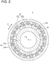
- FIG. 2 is a schematic view of a cross section of a magnetic geared motor 3 along the radial direction according to an embodiment of the present invention.
- FIG. 3 is a view for describing a support mode of the magnetic geared motor 3 in the electric-powered vehicle 1 according to an embodiment of the present invention.
- the electric-powered vehicle 1 is a vehicle that can travel by an electric-powered motor (drive source), such as a railway vehicle, a vehicle of a new transportation system, or an electric car.
- the electric-powered vehicle 1 includes an axle body 2 with an axle 21 extending in a vehicle width direction and drive wheels 22 connected to both ends of the axle 21, the magnetic geared motor 3 for rotating and the above-described axle 21, and an inverter connected to the magnetic geared motor 3.
- the axle 21 is rotary driven as the magnetic geared motor 3 is rotary driven under the control of the inverter, whereby the electric-powered vehicle 1 is configured to travel.
- the electric-powered vehicle 1 may be configured to allow for regenerative braking by the magnetic geared motor, or may be configured to charge a battery 94 with electric power generated by the regenerative braking.
- the above-described magnetic geared motor 3 is configured by integrating a magnetic gear (flux-modulated type magnetic gear) and a motor, and including a stator 31, a low-speed rotor 32, and a high-speed rotor 33.
- the above-described magnetic gear includes an outer diameter side magnet field (stator 31), an inner diameter side magnet field (high-speed rotor 33), and a magnetic pole piece device (low-speed rotor 32), each of which has a cylindrical (annular; the same applies hereinafter) shape as a whole.
- the above-described magnetic gear has a structure where they are disposed at intervals (air gaps Ga) (see FIG. 3 ) of a constant distance from each other in a radial direction c (radial direction) on a same axis 1 (coaxial).
- the outer diameter side magnet field and the inner diameter side magnet field described above, respectively, include magnetic pole pairs (31m, 33m), such as permanent magnets, which are composed of a plurality of N poles and S poles disposed at intervals (regular intervals) on the circumference in a cross section cut along the radial direction c of the magnetic geared motor 3.
- the outer diameter side magnet field (stator 31) includes the plurality of magnetic pole pairs 31m and a stator core 31s which is also in charge of supporting the plurality of magnetic pole pairs 31m.
- the above-described inner diameter side magnet field includes the plurality of magnetic pole pairs 33m and a support member 33s for supporting the plurality of magnetic pole pairs 33m.
- the plurality of magnetic pole pairs 33m are installed over the whole circumference along a circumferential direction a, in the same manner as above.
- the magnetic pole piece device includes a plurality of magnetic pole pieces 32p (pole pieces) disposed at intervals (regular intervals) from each other over the whole circumference in the circumferential direction a.
- a plurality of coils are installed on the outer diameter side magnet field such that magnetic fluxes face the radial direction c and are each used as the stator 31 (stator), and the inner diameter side magnet field (high-speed rotor 33) is rotated by a magnetomotive force of the coils (not shown).
- the magnetic pole piece device (low-speed rotor 32) rotates according to the reduction ratio which is determined by the ratio of the number of pole pairs of the magnetic pole pairs 33m of the inner diameter side magnet field to the number of magnetic pole pieces 32p of the magnetic pole piece device.
- the electric-powered vehicle 1 is a railway vehicle.
- the magnetic geared motor 3 and an inverter 91 are connected by an electric power line.
- the inverter 91 is connected to an overhead line 93 (transmission line) via a transformer 92, and electric power is supplied to the inverter 91. Further, the inverter 91 is connected to the battery 94. Then, the electric power generated by regenerative braking is supplied to the battery 94, and the battery 94 can be charged.
- the electric power generated by the regenerative braking is generally returned to a system side via the overhead line 93 for other railway vehicles, but the battery 94 may directly be charged depending on the condition of the system.
- the electric-powered vehicle 1 shown in FIG. 3 is a railway vehicle.
- Such railway vehicle generally includes a bogie 4a (vehicle structure 4).
- the bogie 4a has a role of supporting a load of a vehicle body (not shown), and a vehicle body (not shown) internally forming a vehicle interior space is mounted on top of the bogie 4a.
- the bogie 4a is connected to the axle 21 by a connecting body 8, thereby assuming the role of absorbing a vibration of the railway vehicle generated by a railway condition, such as a joint of a rail R or traveling on a curve, and of stabilizing the vehicle body (not shown). More specifically, in the embodiment shown in FIG. 3 , each of both ends of the axle 21 and the bogie 4a are connected by the connecting body 8.
- the connecting body 8 includes a bearing 81 for rotatably supporting both ends 21e of the axle 21, and an elastic member 82 (a coil spring in FIG. 3 ) disposed between the bearing 81 and the bogie 4a (vehicle structure 4). Then, the elastic member 82 absorbs an impact or vibration from the side of the rail R and stabilizes the vehicle body (not shown).
- the electric-powered vehicle 1 will be described by taking the above-described railway vehicle as an example.
- the electric-powered vehicle 1 includes the axle body 2 and the magnetic geared motor 3 already described, the vehicle structure 4 (the bogie 4a in FIG. 3 ) supported by the above-described axle body 2, a motor support 5 for connecting the magnetic geared motor 3 and the bogie 4a described above and supporting the magnetic geared motor 3 by the vehicle structure 4 (suspending and supporting downward in FIG. 3 ), and an elastic coupling 6 which is a member for transmitting a rotational force of the low-speed rotor 32 of the magnetic geared motor 3 described above to the axle 21.
- the above-described vehicle structure 4 may be the bogie 4a.
- the above-described vehicle structure 4 may be, for example, a vehicle frame (chassis). Further, the vehicle structure 4 may be supported by the axle 21 via the bearing 81 as shown in FIG. 3 , or may directly be supported by the drive wheels 22 (wheels) instead of the axle 21.
- all (61, 62, 63) of the above-described elastic coupling 6 may each be an elastic body formed of, for example, a rubber member.
- a part of the elastic coupling 6 may include the elastic body 63, and for example, portions mounted on the axle 21 and the low-speed rotor 32, respectively, may be connected via the elastic body 63. That is, as shown in FIG. 3 , the elastic coupling 6 includes the axle mount portion 61 mounted on the axle 21, the motor mount portion 62 mounted on the magnetic geared motor 3 (low-speed rotor 32), and the elastic body 63 for connecting the axle mount portion 61 and the motor mount portion 62.
- the elastic body 63 may be a rubber member, or a spring member such as a leaf spring.
- the axle mount portion 61 is fitted into the axle 21, and the motor mount portion 62 is mounted on the low-speed rotor 32 of the magnetic geared motor 3 by a bolt 61b.
- the elastic body 63 is the spring member, one end of the spring member may be fastened to a flange (not shown) disposed at an axial end of the low-speed rotor 32, and another end of the spring member may be fastened to the axle mount portion 61 joined to the axle 21, by bolts (not shown) inserted into respective bolt holes.
- the low-speed rotor 32 is coupled to the axle 21 by the elastic coupling 6, whereby the axle 21 rotates with the rotation of the low-speed rotor 32.
- a part of the axle 21 extends with a gap Gb with respect to the inner circumferential surface of the high-speed rotor 33, whereby a part of the axle 21 extends non-contactly when the vehicle is stopped. That is, while the axle 21 is disposed in a penetrated state in the high-speed rotor 33 having the cylindrical shape, the high-speed rotor 33 is configured to run idle without contacting the axle 21 when the electric-powered vehicle 1 is traveling.
- the magnetic geared motor 3 is supported below the bogie 4a, and is rigidly suspended and supported by the bogie 4a with the motor support 5.
- the load of the magnetic geared motor 3 does not act directly on the axle 21 but acts indirectly via the bogie 4a. That is, the load of the magnetic geared motor 3 acts on the axle body 2 via the bogie 4a and the connecting body 8, and does not act directly on the axle 21 via the low-speed rotor 32.
- the load when the electric-powered vehicle 1 is stationary naturally acts on the axle body 2
- the load of the magnetic geared motor 3 associated with traveling of the electric-powered vehicle 1 does not act directly on the axle body 2 but acts indirectly on the axle body 2 via the vehicle structure 4 and the connecting body 8.
- the connecting body 8 the dynamic load of the magnetic geared motor 3 acting on the axle body 2
- axle 21 and the low-speed rotor 32 are rigidly coupled instead of the elastic coupling 6, the following inconveniences may occur. More specifically, in the case where the axle 21 and the low-speed rotor 32 are rigidly coupled, if the low-speed rotor 32 is rigidly supported with the side of the stator 31 by a bearing (outer diameter side bearing 7b described later) or the like as shown in FIG. 3 , it is impossible to obtain the effect by the elastic member 82 of the connecting body 8 described above, and the static load and the dynamic load of the magnetic geared motor 3 are applied to the axle 21.
- the electric-powered vehicle 1 further includes an inner diameter side bearing 7a and the outer diameter side bearing 7b, each of which is a rolling bearing.
- the inner diameter side bearing 7a includes a first outer ring fixed to the low-speed rotor 32, a first inner ring fixed to the high-speed rotor 33, and a first rolling element rotatably held between the first outer ring and the first inner ring.
- the outer diameter side bearing 7b includes a second outer ring fixed to the stator 31 (frame portion), a second inner ring fixed to the low-speed rotor 32, and a second rolling element rotatably held between the second outer ring and the second inner ring.
- the outer diameter side bearing 7b connects the stator 31 and the low-speed rotor 32 to allow for a relative rotation thereof, supporting the low-speed rotor 32 by the stator 31.
- the inner diameter side bearing 7a connects the low-speed rotor 32 to allow for a relative rotation thereof, supporting the high-speed rotor 33 by the low-speed rotor 32.
- the magnetic geared motor 3 is supported by the vehicle structure 4, for example, suspended and supported by the vehicle structure 4 (such as the bogie of the railway vehicle or the vehicle frame of the electric car), as well as the low-speed rotor 32 (output shaft) and the axle body 2 are coupled via the elastic coupling 6.
- the vehicle structure 4 such as the bogie of the railway vehicle or the vehicle frame of the electric car
- the low-speed rotor 32 output shaft
- the axle body 2 are coupled via the elastic coupling 6.
- the axle 21 is rotated by the low-speed rotor 32.
- the axle 21 is inclined with respect to the magnetic geared motor 3 depending on the traveling situation, it is possible to absorb such inclination by the elastic coupling 6 while appropriately transmitting power.
- the low-speed rotor 32 is inclined with respect to the surrounding high-speed rotor 33 and the stator 31, it is also possible to protect the magnetic geared motor 3.
- the present invention is not limited to the above-described embodiments, and also includes an embodiment obtained by modifying the above-described embodiments and an embodiment obtained by combining these embodiments as appropriate.
- the magnetic geared motor 3 is suspended and supported by the vehicle structure 4.
- the present invention is not limited to the present embodiment, and the magnetic geared motor 3 may be supported by a method other than suspension, for example, by installation on top of the vehicle structure.
- An electric-powered vehicle (1) includes: an axle body (2) that includes an axle (21) and drive wheels (22) connected to both ends (21e) of the axle (21); a magnetic geared motor (3) for rotating the axle (21), the magnetic geared motor (3) including a stator (31), a low-speed rotor (32), and a high-speed rotor (33); a vehicle structure (4) supported by the axle body (2); a motor support (5) for connecting the vehicle structure (4) and the stator (31), and supporting the magnetic geared motor (3) by the vehicle structure (4); and an elastic coupling (6) for connecting the low-speed rotor (32) and the axle (21) such that a rotational force of the low-speed rotor (32) is transmittable to the axle (21).
- the magnetic geared motor (3) is supported by the vehicle structure (4), for example, suspended and supported by the vehicle structure (4) (such as the bogie (4a) of the railway vehicle or the vehicle frame of the electric car), as well as the low-speed rotor (32) (output shaft) and the axle body (2) are connected via the elastic coupling (6).
- the magnetic geared motor (3) as the drive source of the electric-powered vehicle (1) and supporting the magnetic geared motor (3) by the vehicle structure (4), it is possible to reduce the size and weight of the electric-powered vehicle (1) while reducing the dynamic load of the magnetic geared motor (3) acting on the axle body (2) during traveling of the electric-powered vehicle (1).
- the magnetic geared motor (3) has a coaxial structure where the cylindrical low-speed rotor (32) is sandwiched between the stator (31) on the outer circumferential side and the high-speed rotor (33) on the inner circumferential side while the respective air gaps (Ga) are disposed.
- the magnetic geared motor (3) has a coaxial structure where the cylindrical low-speed rotor (32) is sandwiched between the stator (31) on the outer circumferential side and the high-speed rotor (33) on the inner circumferential side while the respective air gaps (Ga) are disposed.
- the electric-powered vehicle (1) further includes a connecting body (8) for connecting each of the both ends (21e) of the axle (21) and the vehicle structure (4).
- the connecting body (8) includes: a bearing (81) for rotatably supporting the both ends (21e) of the axle (21); and an elastic member (82) disposed between the bearing (81) and the vehicle structure (4).
- the load of the magnetic geared motor (3) acts on the axle body (2) via the vehicle structure (4) and the connecting body (8).
- the connecting body (8) the dynamic load of the magnetic geared motor (3) acting on the axle body (2), and it is possible to reduce the dynamic load as compared with the case where the axle body (2) directly supports the magnetic geared motor (3). Therefore, for example, if the electric-powered vehicle (1) is the railway vehicle, it is possible to suppress wear of or damage to the rail (R) where the drive wheels (22) (wheels) are installed, and it is possible to extend the life of the rail (R).
- the low-speed rotor (3), the high-speed rotor (33), and the stator (31) each have a cylindrical shape
- the low-speed rotor (32) is disposed between the high-speed rotor (33) and the stator (31) disposed on an outer circumferential side of the high-speed rotor (33), and a part of the axle (21) extends without contacting an inner circumferential surface of the high-speed rotor (33) in the high-speed rotor (33).
- the electric-powered vehicle (1) further includes: an inner diameter side bearing (7a) that includes a first outer ring fixed to the low-speed rotor (32), a first inner ring fixed to the high-speed rotor (33), and a first rolling element rotatably held between the first outer ring and the first inner ring; and an outer diameter side bearing (7b) that includes a second outer ring fixed to the stator (31), a second inner ring fixed to the low-speed rotor (32), and a second rolling element rotatably held between the second outer ring and the second inner ring.
- an inner diameter side bearing (7a) that includes a first outer ring fixed to the low-speed rotor (32), a first inner ring fixed to the high-speed rotor (33), and a first rolling element rotatably held between the first outer ring and the first inner ring
- an outer diameter side bearing (7b) that includes a second outer ring fixed to the stator (31), a second inner ring fixed to the low-
- the high-speed rotor (33) and the low-speed rotor (32) are connected to the stator (31) via the two bearings (81).
- the magnetic geared motor (3) it is possible to support the magnetic geared motor (3) by the vehicle structure (4) more appropriately.
- the elastic coupling (6) includes: an axle mount portion (61) mounted on the axle (21); a motor mount portion (62) mounted on the low-speed rotor (32); and an elastic body (63) for connecting the axle mount portion (61) and the motor mount portion (62).
- the elastic coupling (6) can appropriately connect the axle (21) and the low-speed rotor (32) while appropriately transmitting the rotation of the low-speed rotor (32) to the axle (21).
- the elastic body (63) is a rubber member.
- the elastic body (63) is a spring member.
- the electric-powered vehicle (1) is a railway vehicle
- the vehicle structure (4) is a bogie (4a) of the railway vehicle
- the magnetic geared motor (3) is suspended and supported by the motor support (5).
- the electric-powered vehicle (1) is the railway vehicle whose drive source is the magnetic geared motor (3), and the magnetic geared motor (3) is suspended and supported by the bogie (4a) of the railway vehicle.
- the same effects as in the above configurations (1) to (7) are achieved.
Landscapes
- Engineering & Computer Science (AREA)
- Power Engineering (AREA)
- Chemical & Material Sciences (AREA)
- Combustion & Propulsion (AREA)
- Transportation (AREA)
- Mechanical Engineering (AREA)
- Connection Of Motors, Electrical Generators, Mechanical Devices, And The Like (AREA)
- Dynamo-Electric Clutches, Dynamo-Electric Brakes (AREA)
Abstract
Description
- The present disclosure relates to an electric-powered vehicle.
- The present application claims priority on
Japanese Patent Application No. 2020-005600 filed on January 17, 2020 - A railway vehicle is required of a reduction in weight of the vehicle for high efficiency, high speed, and maintenance saving, as well as securing an interior space and equipment loading space, or space saving of a drive device for lowering a floor. So far, the miniaturization and the weight reduction have been promoted by replacing an induction motor with a permanent magnet motor or replacing an IGBT inverter with a SiC inverter. For example, in Patent Document 1, a motor for driving an axle is mounted by installing its housing on the axle and being connected to a chassis beam via an elastic control arm.
- Meanwhile, a flux-modulated type (harmonic type) magnetic gear is known as a kind of gear device. The magnetic gear includes is an inner circumferential side magnet field and an outer circumferential side magnet field concentrically (coaxially) disposed, and a magnetic pole piece device which has a plurality of magnetic pole pieces (pole pieces) and a plurality of non-magnetic bodies each being disposed with a gap (air gap) between these two magnet fields and alternately arranged in the circumferential direction (see
Patent Documents 2 and 3). Then, a magnetic flux of magnets of the above-described two magnet fields is modulated by each of the above-described magnetic pole pieces to generate a harmonic magnetic flux, and the above-described two magnet fields are synchronized with the harmonic magnetic flux, thereby operating the flux-modulated type magnetic gear. For example, in a magnetic geared motor in which the flux-modulated type magnetic gear and a motor are integrated, the above-described outer circumferential side magnet field is fixed to function as a stator, as well as the above-described inner circumferential side magnet field is functioned as a high-speed rotor and the above-described magnetic pole piece device is functioned as a low-speed rotor. Then, by rotating the high-speed rotor by a magnetomotive force of a coil, the low-speed rotor rotates according to the reduction ratio. -
- Patent Document 1:
US6868793B - Patent Document 2:
US9425655B - Patent Document 3:
JP5286373B - For example, a railway vehicle travels on a rail, but if a large load is applied to the rail, damage to the rail, such as wear, is likely to occur accordingly. Generally, in the railway vehicle, an axle body including an axle and wheels is connected to a bogie for supporting a vehicle body via a spring or the like, and in order to prevent the damage to the rail, it is desirable that the weight of the axle body is small. In this respect, a speed reducer becomes unnecessary, for example, by directly driving the axle with a motor as in Patent Document 1, but the weight of the motor tends to increase and there is a problem in terms of a weight reduction of an electric-powered vehicle. Thus, the present inventors have considered adopting, as a drive source for the electric-powered vehicle such as the railway vehicle, a magnetic geared motor which can be smaller and lighter than a motor such as a permanent magnet motor.
- However, if the motor is configured to directly be supported by the axle, for example, by installing the motor housing on a bearing as in Patent Document 1, not to mention a load (static load) of the motor when the electric-powered vehicle is stationary, a full load (dynamic load) of the motor associated with traveling of the electric-powered vehicle acts on the axle. Consequently, since the full dynamic load acting on the axle directly acts on the rail for supporting the axle via the wheels (driving wheels), the damage to the rail is likely to occur. In this respect, in the electric-powered vehicle, the axle and the vehicle body side are usually connected via the spring or the like. However, the present inventors have found that it is possible to reduce the dynamic load of the magnetic geared motor acting on the rail (road surface), by suspending and supporting the magnetic geared motor by a vehicle structure such as a bogie of a railway vehicle.
- In view of the above, an object of at least one embodiment of the present invention is to provide the electric-powered vehicle capable of reducing the dynamic load of the magnetic geared motor acting on the axle body.
- An electric-powered vehicle according to at least one embodiment of the present invention includes: an axle body that includes an axle and drive wheels connected to both ends of the axle; a magnetic geared motor for rotating the axle, the magnetic geared motor including a stator, a low-speed rotor, and a high-speed rotor; a vehicle structure supported by the axle body; a motor support for connecting the vehicle structure and the stator, and supporting the magnetic geared motor by the vehicle structure; and an elastic coupling for coupling the low-speed rotor and the axle such that a rotational force of the low-speed rotor is transmittable to the axle.
- According to at least one embodiment of the present invention, an electric-powered vehicle is provided which is capable of reducing a dynamic load of a magnetic geared motor acting on an axle body.
-
-
FIG. 1 is a schematic diagram showing a drive device for an electric-powered vehicle according to an embodiment of the present invention. -
FIG. 2 is a view for describing a support mode of a magnetic geared motor in the electric-powered vehicle according to an embodiment of the present invention. -
FIG. 3 is a view for describing a support mode of the magnetic geared motor in a railway vehicle (electric-powered vehicle) according to an embodiment of the present invention. - Some embodiments of the present invention will be described below with reference to the accompanying drawings. It is intended, however, that unless particularly identified, dimensions, materials, shapes, relative positions and the like of components described or shown in the drawings as the embodiments shall be interpreted as illustrative only and not intended to limit the scope of the present invention.
- For instance, an expression of relative or absolute arrangement such as "in a direction", "along a direction", "parallel", "orthogonal", "centered", "concentric" and "coaxial" shall not be construed as indicating only the arrangement in a strict literal sense, but also includes a state where the arrangement is relatively displaced by a tolerance, or by an angle or a distance whereby it is possible to achieve the same function.
- For instance, an expression of an equal state such as "same", "equal", and "uniform" shall not be construed as indicating only the state in which the feature is strictly equal, but also includes a state in which there is a tolerance or a difference that can still achieve the same function.
- Further, for instance, an expression of a shape such as a rectangular shape or a tubular shape shall not be construed as only the geometrically strict shape, but also includes a shape with unevenness or chamfered corners within the range in which the same effect can be achieved.
- On the other hand, the expressions "comprising", "including", "having", "containing", and "constituting" one constituent component are not exclusive expressions that exclude the presence of other constituent components.
-
FIG. 1 is a schematic diagram showing a drive device for an electric-powered vehicle 1 according to an embodiment of the present invention.FIG. 2 is a schematic view of a cross section of a magnetic gearedmotor 3 along the radial direction according to an embodiment of the present invention. Further,FIG. 3 is a view for describing a support mode of the magnetic gearedmotor 3 in the electric-powered vehicle 1 according to an embodiment of the present invention. - The electric-powered vehicle 1 is a vehicle that can travel by an electric-powered motor (drive source), such as a railway vehicle, a vehicle of a new transportation system, or an electric car. As shown in
FIG. 1 , the electric-powered vehicle 1 includes anaxle body 2 with anaxle 21 extending in a vehicle width direction anddrive wheels 22 connected to both ends of theaxle 21, the magnetic gearedmotor 3 for rotating and the above-describedaxle 21, and an inverter connected to the magnetic gearedmotor 3. Then, theaxle 21 is rotary driven as the magnetic gearedmotor 3 is rotary driven under the control of the inverter, whereby the electric-powered vehicle 1 is configured to travel. The electric-powered vehicle 1 may be configured to allow for regenerative braking by the magnetic geared motor, or may be configured to charge abattery 94 with electric power generated by the regenerative braking. - More specifically, the above-described magnetic geared
motor 3 is configured by integrating a magnetic gear (flux-modulated type magnetic gear) and a motor, and including astator 31, a low-speed rotor 32, and a high-speed rotor 33. Describing in detail, as shown inFIG. 2 , the above-described magnetic gear includes an outer diameter side magnet field (stator 31), an inner diameter side magnet field (high-speed rotor 33), and a magnetic pole piece device (low-speed rotor 32), each of which has a cylindrical (annular; the same applies hereinafter) shape as a whole. Then, when the magnetic pole piece device is disposed between the outer diameter side magnet field and the inner diameter side magnet field, the above-described magnetic gear has a structure where they are disposed at intervals (air gaps Ga) (seeFIG. 3 ) of a constant distance from each other in a radial direction c (radial direction) on a same axis 1 (coaxial). - Further, as shown in
FIG. 2 , the outer diameter side magnet field and the inner diameter side magnet field described above, respectively, include magnetic pole pairs (31m, 33m), such as permanent magnets, which are composed of a plurality of N poles and S poles disposed at intervals (regular intervals) on the circumference in a cross section cut along the radial direction c of the magnetic gearedmotor 3. More specifically, the outer diameter side magnet field (stator 31) includes the plurality ofmagnetic pole pairs 31m and astator core 31s which is also in charge of supporting the plurality ofmagnetic pole pairs 31m. Then, on the cylindrical inner circumferential surface of the outer diameter side magnet field, the plurality ofmagnetic pole pairs 31m are installed over the whole circumference in a state where the magnetic poles face the radial direction c and such that the N poles and the S poles are alternated along the circumferential direction. Likewise, the above-described inner diameter side magnet field (high-speed rotor 33) includes the plurality ofmagnetic pole pairs 33m and asupport member 33s for supporting the plurality ofmagnetic pole pairs 33m. Then, on the cylindrical outer circumferential surface of the inner diameter side magnet field, the plurality ofmagnetic pole pairs 33m are installed over the whole circumference along a circumferential direction a, in the same manner as above. Further, the magnetic pole piece device (low-speed rotor 32) includes a plurality ofmagnetic pole pieces 32p (pole pieces) disposed at intervals (regular intervals) from each other over the whole circumference in the circumferential direction a. - Then, as shown in
FIG. 2 , a plurality of coils (not shown) are installed on the outer diameter side magnet field such that magnetic fluxes face the radial direction c and are each used as the stator 31 (stator), and the inner diameter side magnet field (high-speed rotor 33) is rotated by a magnetomotive force of the coils (not shown). Thus, the magnetic pole piece device (low-speed rotor 32) rotates according to the reduction ratio which is determined by the ratio of the number of pole pairs of themagnetic pole pairs 33m of the inner diameter side magnet field to the number ofmagnetic pole pieces 32p of the magnetic pole piece device. - In the embodiments shown in
FIGs. 1 to 3 , the electric-powered vehicle 1 is a railway vehicle. The magnetic gearedmotor 3 and aninverter 91 are connected by an electric power line. Theinverter 91 is connected to an overhead line 93 (transmission line) via atransformer 92, and electric power is supplied to theinverter 91. Further, theinverter 91 is connected to thebattery 94. Then, the electric power generated by regenerative braking is supplied to thebattery 94, and thebattery 94 can be charged. In the railway vehicle, the electric power generated by the regenerative braking is generally returned to a system side via theoverhead line 93 for other railway vehicles, but thebattery 94 may directly be charged depending on the condition of the system. - Next, a support mode of the magnetic geared
motor 3 in the railway vehicle (electric-powered vehicle 1) having the above-described configuration will be described with reference toFIG. 3 . - The electric-powered vehicle 1 shown in
FIG. 3 is a railway vehicle. Such railway vehicle generally includes abogie 4a (vehicle structure 4). Thebogie 4a has a role of supporting a load of a vehicle body (not shown), and a vehicle body (not shown) internally forming a vehicle interior space is mounted on top of thebogie 4a. - Further, the
bogie 4a is connected to theaxle 21 by a connectingbody 8, thereby assuming the role of absorbing a vibration of the railway vehicle generated by a railway condition, such as a joint of a rail R or traveling on a curve, and of stabilizing the vehicle body (not shown). More specifically, in the embodiment shown inFIG. 3 , each of both ends of theaxle 21 and thebogie 4a are connected by the connectingbody 8. The connectingbody 8 includes abearing 81 for rotatably supporting bothends 21e of theaxle 21, and an elastic member 82 (a coil spring inFIG. 3 ) disposed between the bearing 81 and thebogie 4a (vehicle structure 4). Then, theelastic member 82 absorbs an impact or vibration from the side of the rail R and stabilizes the vehicle body (not shown). - Hereinafter, the electric-powered vehicle 1 will be described by taking the above-described railway vehicle as an example.
- As shown in
FIG. 3 , the electric-powered vehicle 1 includes theaxle body 2 and the magnetic gearedmotor 3 already described, the vehicle structure 4 (thebogie 4a inFIG. 3 ) supported by the above-describedaxle body 2, amotor support 5 for connecting the magnetic gearedmotor 3 and thebogie 4a described above and supporting the magnetic gearedmotor 3 by the vehicle structure 4 (suspending and supporting downward inFIG. 3 ), and anelastic coupling 6 which is a member for transmitting a rotational force of the low-speed rotor 32 of the magnetic gearedmotor 3 described above to theaxle 21. - In the case of the railway vehicle or the vehicle of the new transportation system, the above-described
vehicle structure 4 may be thebogie 4a. In the case of the electric car, the above-describedvehicle structure 4 may be, for example, a vehicle frame (chassis). Further, thevehicle structure 4 may be supported by theaxle 21 via thebearing 81 as shown inFIG. 3 , or may directly be supported by the drive wheels 22 (wheels) instead of theaxle 21. - Further, all (61, 62, 63) of the above-described
elastic coupling 6 may each be an elastic body formed of, for example, a rubber member. Alternatively, a part of theelastic coupling 6 may include theelastic body 63, and for example, portions mounted on theaxle 21 and the low-speed rotor 32, respectively, may be connected via theelastic body 63. That is, as shown inFIG. 3 , theelastic coupling 6 includes the axle mount portion 61 mounted on theaxle 21, themotor mount portion 62 mounted on the magnetic geared motor 3 (low-speed rotor 32), and theelastic body 63 for connecting the axle mount portion 61 and themotor mount portion 62. Theelastic body 63 may be a rubber member, or a spring member such as a leaf spring. - In the embodiment shown in
FIG. 3 , the axle mount portion 61 is fitted into theaxle 21, and themotor mount portion 62 is mounted on the low-speed rotor 32 of the magnetic gearedmotor 3 by abolt 61b. If theelastic body 63 is the spring member, one end of the spring member may be fastened to a flange (not shown) disposed at an axial end of the low-speed rotor 32, and another end of the spring member may be fastened to the axle mount portion 61 joined to theaxle 21, by bolts (not shown) inserted into respective bolt holes. - Then, in the magnetic geared
motor 3 of the electric-powered vehicle 1, the low-speed rotor 32 is coupled to theaxle 21 by theelastic coupling 6, whereby theaxle 21 rotates with the rotation of the low-speed rotor 32. Further, in the high-speed rotor 33, a part of theaxle 21 extends with a gap Gb with respect to the inner circumferential surface of the high-speed rotor 33, whereby a part of theaxle 21 extends non-contactly when the vehicle is stopped. That is, while theaxle 21 is disposed in a penetrated state in the high-speed rotor 33 having the cylindrical shape, the high-speed rotor 33 is configured to run idle without contacting theaxle 21 when the electric-powered vehicle 1 is traveling. By connecting thestator 31 to themotor support 5 in this state, most (all) of the load of the magnetic gearedmotor 3 is supported by thebogie 4a. - That is, in the embodiment shown in
FIG. 3 , the magnetic gearedmotor 3 is supported below thebogie 4a, and is rigidly suspended and supported by thebogie 4a with themotor support 5. Thus, the load of the magnetic gearedmotor 3 does not act directly on theaxle 21 but acts indirectly via thebogie 4a. That is, the load of the magnetic gearedmotor 3 acts on theaxle body 2 via thebogie 4a and the connectingbody 8, and does not act directly on theaxle 21 via the low-speed rotor 32. - With the above configuration, although the load when the electric-powered vehicle 1 is stationary (hereinafter, static load) naturally acts on the
axle body 2, the load of the magnetic gearedmotor 3 associated with traveling of the electric-powered vehicle 1 (hereinafter, dynamic load) does not act directly on theaxle body 2 but acts indirectly on theaxle body 2 via thevehicle structure 4 and the connectingbody 8. Thus, it is possible to absorb, by the connectingbody 8, the dynamic load of the magnetic gearedmotor 3 acting on theaxle body 2, and it is possible to reduce the dynamic load as compared with the case where theaxle body 2 directly supports the magnetic gearedmotor 3. Therefore, for example, if the electric-powered vehicle 1 is the railway vehicle, it is possible to suppress wear of or damage to the rail R where the drive wheels 22 (wheels) are installed, and it is possible to extend the life of the rail R. - Further, if the
axle 21 and the low-speed rotor 32 are rigidly coupled instead of theelastic coupling 6, the following inconveniences may occur. More specifically, in the case where theaxle 21 and the low-speed rotor 32 are rigidly coupled, if the low-speed rotor 32 is rigidly supported with the side of thestator 31 by a bearing (outer diameter side bearing 7b described later) or the like as shown inFIG. 3 , it is impossible to obtain the effect by theelastic member 82 of the connectingbody 8 described above, and the static load and the dynamic load of the magnetic gearedmotor 3 are applied to theaxle 21. At this time, if the rigidity of the connection portion between the low-speed rotor 32 and theaxle 21 is low, the presence of theelastic member 82 of the connectingbody 8 described above also causes inclination of the low-speed rotor 32 in the magnetic gearedmotor 3. Thus, by connecting theaxle 21 and the low-speed rotor 32 with theelastic coupling 6, it is possible to suppress the above-described two movements. - Moreover, in the embodiment shown in
FIG. 3 , the electric-powered vehicle 1 further includes an inner diameter side bearing 7a and the outer diameter side bearing 7b, each of which is a rolling bearing. The inner diameter side bearing 7a includes a first outer ring fixed to the low-speed rotor 32, a first inner ring fixed to the high-speed rotor 33, and a first rolling element rotatably held between the first outer ring and the first inner ring. Further, the outer diameter side bearing 7b includes a second outer ring fixed to the stator 31 (frame portion), a second inner ring fixed to the low-speed rotor 32, and a second rolling element rotatably held between the second outer ring and the second inner ring. - That is, the outer diameter side bearing 7b connects the
stator 31 and the low-speed rotor 32 to allow for a relative rotation thereof, supporting the low-speed rotor 32 by thestator 31. Further, the inner diameter side bearing 7a connects the low-speed rotor 32 to allow for a relative rotation thereof, supporting the high-speed rotor 33 by the low-speed rotor 32. Thus, it is possible to support the magnetic gearedmotor 3 by thevehicle structure 4 more appropriately. - With the above configuration, in the electric-powered vehicle 1, the magnetic geared
motor 3 is supported by thevehicle structure 4, for example, suspended and supported by the vehicle structure 4 (such as the bogie of the railway vehicle or the vehicle frame of the electric car), as well as the low-speed rotor 32 (output shaft) and theaxle body 2 are coupled via theelastic coupling 6. As described above, by using the magnetic gearedmotor 3 as the drive source of the electric-powered vehicle 1 and supporting the magnetic gearedmotor 3 by thevehicle structure 4, it is possible to reduce the size and weight of the electric-powered vehicle 1 while reducing the dynamic load of the magnetic gearedmotor 3 acting during traveling of the electric-powered vehicle 1. - Further, since the low-
speed rotor 32 of the magnetic gearedmotor 3 and theaxle 21 of theaxle body 2 are coupled via theelastic coupling 6, theaxle 21 is rotated by the low-speed rotor 32. Thus, for example, even if theaxle 21 is inclined with respect to the magnetic gearedmotor 3 depending on the traveling situation, it is possible to absorb such inclination by theelastic coupling 6 while appropriately transmitting power. Further, by suppressing that the low-speed rotor 32 is inclined with respect to the surrounding high-speed rotor 33 and thestator 31, it is also possible to protect the magnetic gearedmotor 3. - The present invention is not limited to the above-described embodiments, and also includes an embodiment obtained by modifying the above-described embodiments and an embodiment obtained by combining these embodiments as appropriate.
- In the above-described embodiment, the magnetic geared
motor 3 is suspended and supported by thevehicle structure 4. However, the present invention is not limited to the present embodiment, and the magnetic gearedmotor 3 may be supported by a method other than suspension, for example, by installation on top of the vehicle structure. - (1) An electric-powered vehicle (1) according to at least one embodiment of the present invention includes: an axle body (2) that includes an axle (21) and drive wheels (22) connected to both ends (21e) of the axle (21); a magnetic geared motor (3) for rotating the axle (21), the magnetic geared motor (3) including a stator (31), a low-speed rotor (32), and a high-speed rotor (33); a vehicle structure (4) supported by the axle body (2); a motor support (5) for connecting the vehicle structure (4) and the stator (31), and supporting the magnetic geared motor (3) by the vehicle structure (4); and an elastic coupling (6) for connecting the low-speed rotor (32) and the axle (21) such that a rotational force of the low-speed rotor (32) is transmittable to the axle (21).
- With the above configuration (1), in the electric-powered vehicle (1) which is, for example, the railway vehicle, the vehicle of the new transportation system, or the electric car, the magnetic geared motor (3) is supported by the vehicle structure (4), for example, suspended and supported by the vehicle structure (4) (such as the bogie (4a) of the railway vehicle or the vehicle frame of the electric car), as well as the low-speed rotor (32) (output shaft) and the axle body (2) are connected via the elastic coupling (6). As described above, by using the magnetic geared motor (3) as the drive source of the electric-powered vehicle (1) and supporting the magnetic geared motor (3) by the vehicle structure (4), it is possible to reduce the size and weight of the electric-powered vehicle (1) while reducing the dynamic load of the magnetic geared motor (3) acting on the axle body (2) during traveling of the electric-powered vehicle (1).
- Further, since the low-speed rotor (32) of the magnetic geared motor (3) and the axle (21) of the axle body (2) are connected via the elastic coupling (6), the axle (21) is rotated by the low-speed rotor (32). Thus, for example, even if the axle (21) is inclined with respect to the magnetic geared motor (3) depending on the traveling situation, it is possible to absorb such inclination by the elastic coupling (6) while appropriately transmitting power. Further, the magnetic geared motor (3) has a coaxial structure where the cylindrical low-speed rotor (32) is sandwiched between the stator (31) on the outer circumferential side and the high-speed rotor (33) on the inner circumferential side while the respective air gaps (Ga) are disposed. However, by suppressing that the low-speed rotor (32) is inclined with respect to the surrounding high-speed rotor (33) and the stator (31), it is also possible to protect the magnetic geared motor (3).
- (2) In some embodiments, in the above configuration (1), the electric-powered vehicle (1) further includes a connecting body (8) for connecting each of the both ends (21e) of the axle (21) and the vehicle structure (4). The connecting body (8) includes: a bearing (81) for rotatably supporting the both ends (21e) of the axle (21); and an elastic member (82) disposed between the bearing (81) and the vehicle structure (4).
- With the above configuration (2), the load of the magnetic geared motor (3) acts on the axle body (2) via the vehicle structure (4) and the connecting body (8). Thus, it is possible to absorb, by the connecting body (8), the dynamic load of the magnetic geared motor (3) acting on the axle body (2), and it is possible to reduce the dynamic load as compared with the case where the axle body (2) directly supports the magnetic geared motor (3). Therefore, for example, if the electric-powered vehicle (1) is the railway vehicle, it is possible to suppress wear of or damage to the rail (R) where the drive wheels (22) (wheels) are installed, and it is possible to extend the life of the rail (R).
- (3) In some embodiments, in the above configurations (1) or (2), the low-speed rotor (3), the high-speed rotor (33), and the stator (31) each have a cylindrical shape, the low-speed rotor (32) is disposed between the high-speed rotor (33) and the stator (31) disposed on an outer circumferential side of the high-speed rotor (33), and a part of the axle (21) extends without contacting an inner circumferential surface of the high-speed rotor (33) in the high-speed rotor (33).
- With the above configuration (3), while the axle (21) is disposed in a penetrated state in the high-speed rotor (33) having the cylindrical shape, a part of the axle (21) is configured to extend with the gap (Gb) with respect to the inner circumferential surface of the high-speed rotor (33). Thus, the more appropriate support is possible such that the load of the magnetic geared motor (3) acts via the vehicle structure (4) instead of directly acting on the axle body (2), and it is possible to reduce the dynamic load of the magnetic geared motor (3) acting on the axle body (2) during traveling of the electric-powered vehicle (1).
- (4) In some embodiments, in the above configurations (1) to (3), the electric-powered vehicle (1) further includes: an inner diameter side bearing (7a) that includes a first outer ring fixed to the low-speed rotor (32), a first inner ring fixed to the high-speed rotor (33), and a first rolling element rotatably held between the first outer ring and the first inner ring; and an outer diameter side bearing (7b) that includes a second outer ring fixed to the stator (31), a second inner ring fixed to the low-speed rotor (32), and a second rolling element rotatably held between the second outer ring and the second inner ring.
- With the above configuration (4), the high-speed rotor (33) and the low-speed rotor (32) are connected to the stator (31) via the two bearings (81). Thus, it is possible to support the magnetic geared motor (3) by the vehicle structure (4) more appropriately.
- (5) In some embodiments, in the above configurations (1) to (4), the elastic coupling (6) includes: an axle mount portion (61) mounted on the axle (21); a motor mount portion (62) mounted on the low-speed rotor (32); and an elastic body (63) for connecting the axle mount portion (61) and the motor mount portion (62).
- With the above configuration (5), the elastic coupling (6) can appropriately connect the axle (21) and the low-speed rotor (32) while appropriately transmitting the rotation of the low-speed rotor (32) to the axle (21).
- (6) In some embodiments, in the above configuration (5), the elastic body (63) is a rubber member.
- With the above configuration (6), it is possible to appropriately absorb, by the rubber member, the inclination of the axle (21) with respect to the magnetic geared motor (3).
- (7) In some embodiments, in the above configuration (5), the elastic body (63) is a spring member.
- With the above configuration (7), it is possible to appropriately absorb, by the spring member such as the leaf spring, the inclination of the axle (21) with respect to the magnetic geared motor (3).
- (8) In some embodiments, in the above configurations (1) to (7), the electric-powered vehicle (1) is a railway vehicle, the vehicle structure (4) is a bogie (4a) of the railway vehicle, and the magnetic geared motor (3) is suspended and supported by the motor support (5).
- With the above configuration (8), the electric-powered vehicle (1) is the railway vehicle whose drive source is the magnetic geared motor (3), and the magnetic geared motor (3) is suspended and supported by the bogie (4a) of the railway vehicle. Thus, the same effects as in the above configurations (1) to (7) are achieved.
-
- 1
- Electric-powered vehicle
- 2
- Axle body
- 21
- Axle
- 21e
- End
- 22
- Drive wheel
- 3
- Magnetic geared motor
- 31
- Stator
- 31m
- Magnetic pole pair (stator)
- 31s
- Stator core (stator)
- 32
- Low-speed rotor
- 32p
- Magnetic pole piece
- 33
- High-speed rotor
- 33m
- Magnetic pole pair (high-speed rotor)
- 33s
- Support member (high-speed rotor)
- 4
- Vehicle structure
- 4a
- Bogie
- 5
- Motor support
- 6
- Elastic coupling
- 61
- Axle mount portion
- 61b
- Bolt
- 62
- Motor mount portion
- 63
- Elastic body
- 7a
- Inner diameter side bearing
- 7b
- Outer diameter side bearing
- 8
- Connecting body
- 81
- Bearing
- 82
- Elastic member
- 91
- Inverter
- 92
- Transformer
- 93
- Overhead line
- 94
- Battery
- Ga
- Air gap
- Gb
- Gap (between axle and high-speed rotor)
- a
- Circumferential direction
- c
- Radial direction
- 1
- Axis
- R
- Rail
Claims (8)
- An electric-powered vehicle, comprising:an axle body that includes an axle and drive wheels connected to both ends of the axle;a magnetic geared motor for rotating the axle, the magnetic geared motor including a stator, a low-speed rotor, and a high-speed rotor;a vehicle structure supported by the axle body;a motor support for connecting the vehicle structure and the stator, and supporting the magnetic geared motor by the vehicle structure; andan elastic coupling for coupling the low-speed rotor and the axle such that a rotational force of the low-speed rotor is transmittable to the axle.
- The electric-powered vehicle according to claim 1, further comprising:a connecting body for connecting each of the both ends of the axle and the vehicle structure,wherein the connecting body includes:a bearing for rotatably supporting the both ends of the axle; andan elastic member disposed between the bearing and the vehicle structure.
- The electric-powered vehicle according to claim 1 or 2,wherein the low-speed rotor, the high-speed rotor, and the stator each have a cylindrical shape,wherein the low-speed rotor is disposed between the high-speed rotor and the stator disposed on an outer circumferential side of the high-speed rotor, andwherein a part of the axle extends without contacting an inner circumferential surface of the high-speed rotor in the high-speed rotor.
- The electric-powered vehicle according to any one of claims 1 to 3, further comprising:an inner diameter side bearing that includes a first outer ring fixed to the low-speed rotor, a first inner ring fixed to the high-speed rotor, and a first rolling element rotatably held between the first outer ring and the first inner ring; andan outer diameter side bearing that includes a second outer ring fixed to the stator, a second inner ring fixed to the low-speed rotor, and a second rolling element rotatably held between the second outer ring and the second inner ring.
- The electric-powered vehicle according to any one of claims 1 to 4,
wherein the elastic coupling includes:an axle mount portion mounted on the axle;a motor mount portion mounted on the low-speed rotor; andan elastic body for connecting the axle mount portion and the motor mount portion. - The electric-powered vehicle according to claim 5,
wherein the elastic body is a rubber member. - The electric-powered vehicle according to claim 5,
wherein the elastic body is a spring member. - The electric-powered vehicle according to any one of claims 1 to 7,wherein the electric-powered vehicle is a railway vehicle,wherein the vehicle structure is a bogie of the railway vehicle, andwherein the magnetic geared motor is suspended and supported by the motor support.
Applications Claiming Priority (2)
| Application Number | Priority Date | Filing Date | Title |
|---|---|---|---|
| JP2020005600A JP7493340B2 (en) | 2020-01-17 | 2020-01-17 | Electric vehicles |
| PCT/JP2021/000325 WO2021145264A1 (en) | 2020-01-17 | 2021-01-07 | Electric vehicle |
Publications (3)
| Publication Number | Publication Date |
|---|---|
| EP4074571A1 true EP4074571A1 (en) | 2022-10-19 |
| EP4074571A4 EP4074571A4 (en) | 2023-02-08 |
| EP4074571B1 EP4074571B1 (en) | 2023-12-20 |
Family
ID=76864621
Family Applications (1)
| Application Number | Title | Priority Date | Filing Date |
|---|---|---|---|
| EP21741898.7A Active EP4074571B1 (en) | 2020-01-17 | 2021-01-07 | Electric vehicle |
Country Status (5)
| Country | Link |
|---|---|
| US (1) | US12534114B2 (en) |
| EP (1) | EP4074571B1 (en) |
| JP (1) | JP7493340B2 (en) |
| CN (1) | CN114929546B (en) |
| WO (1) | WO2021145264A1 (en) |
Families Citing this family (7)
| Publication number | Priority date | Publication date | Assignee | Title |
|---|---|---|---|---|
| JP7493340B2 (en) * | 2020-01-17 | 2024-05-31 | 三菱重工業株式会社 | Electric vehicles |
| JP7679012B2 (en) * | 2021-09-14 | 2025-05-19 | 三菱重工業株式会社 | Magnetic geared rotating machine, power generation system, and drive system |
| JP7291283B1 (en) | 2022-09-26 | 2023-06-14 | 三菱重工業株式会社 | magnetic geared electromechanical |
| JP7748069B2 (en) * | 2022-10-28 | 2025-10-02 | 三菱重工業株式会社 | Magnetic gears and magnetically geared electric machines |
| CN115973265B (en) * | 2023-01-05 | 2025-11-25 | 清华大学 | A magnetic screw integrated steer-by-wire system and vehicle |
| GB2632795A (en) * | 2023-08-16 | 2025-02-26 | Transp Ip Holdings Llc | Propulsion and/or braking control system |
| JP2025183660A (en) * | 2024-06-05 | 2025-12-17 | 三菱重工業株式会社 | Protection device, drive system, protection method, program, main control device, and inverter control device |
Family Cites Families (38)
| Publication number | Priority date | Publication date | Assignee | Title |
|---|---|---|---|---|
| US4270622A (en) * | 1979-06-27 | 1981-06-02 | Travis James M | Drive axle for electric vehicle |
| US5680908A (en) * | 1996-01-29 | 1997-10-28 | Reed; Louis | Electric powered vehicle |
| US5893425A (en) * | 1996-07-22 | 1999-04-13 | Finkle; Louis J. | Remote control electric powered skateboard |
| JP3463259B2 (en) * | 1998-06-05 | 2003-11-05 | 東日本旅客鉄道株式会社 | Vehicle drive |
| JP4235929B2 (en) * | 1999-06-24 | 2009-03-11 | 東日本旅客鉄道株式会社 | Vehicle drive device |
| DE10047911A1 (en) * | 2000-09-27 | 2002-04-18 | Siemens Ag | Drive a wheelset |
| JP4013487B2 (en) * | 2001-02-28 | 2007-11-28 | 株式会社日立製作所 | Rotating electric machine and vehicle equipped with the same |
| JP2004297868A (en) * | 2003-03-26 | 2004-10-21 | Railway Technical Res Inst | Synchronous motor for electric railway vehicles |
| DE10345888B4 (en) | 2003-09-30 | 2006-11-23 | Siemens Ag | Electric direct drive |
| GB2437568B (en) * | 2006-04-24 | 2009-02-11 | Univ Sheffield | Electrical machines |
| US8113307B2 (en) * | 2006-11-17 | 2012-02-14 | Holland Ronald A | Electric vehicle drive system |
| GB0800463D0 (en) * | 2008-01-11 | 2008-02-20 | Magnomatics Ltd | Magnetic drive systems |
| CN101330234A (en) * | 2008-04-21 | 2008-12-24 | 上海大学 | Direct-drive composite permanent magnet motor |
| GB0808524D0 (en) * | 2008-05-12 | 2008-06-18 | Magnomatics Ltd | Magnetic pole-piece structure |
| JP5288373B2 (en) | 2008-07-04 | 2013-09-11 | 株式会社アルトエイジ | Chair |
| US20100241298A1 (en) * | 2009-03-20 | 2010-09-23 | Raymond Anthony Sinke | Electric powered outdrive |
| GB2472020A (en) * | 2009-07-21 | 2011-01-26 | Interroll Trommelmotoren Gmbh | A drum motor including a magnetic gear arrangment |
| US8167061B2 (en) * | 2010-01-11 | 2012-05-01 | GM Global Technology Operations LLC | Electric powered cart for moving loads |
| JP5286373B2 (en) | 2011-01-28 | 2013-09-11 | 株式会社日立製作所 | Magnetic gear |
| US9132735B2 (en) * | 2011-02-17 | 2015-09-15 | George Black | Electric car systems |
| US9079482B2 (en) * | 2011-02-25 | 2015-07-14 | Deere & Company | Powered vehicle with an independent and interchangeable powertrain assembly |
| US20120217074A1 (en) * | 2011-02-28 | 2012-08-30 | Rudinec Stephen A | All-Electric Powered Vehicle |
| US9170081B2 (en) * | 2012-02-23 | 2015-10-27 | Oldenburg Group Incorporated | All-electric powered ANFO vehicle |
| CN203094064U (en) * | 2012-12-26 | 2013-07-31 | 南车青岛四方机车车辆股份有限公司 | 100% low floor vehicle independent wheel coupling driving device |
| US9438096B2 (en) * | 2013-07-30 | 2016-09-06 | Praxair Technology, Inc. | Electric motor and magnetic gear |
| FR3014399B1 (en) * | 2013-12-11 | 2017-05-26 | Alstom Transport Sa | BOGIE RAIL VEHICLE ENGINE IN WHICH THE ENGINE IS SUBSTANTIALLY COAXIAL AT THE AXLE |
| EP2883775A1 (en) * | 2013-12-13 | 2015-06-17 | Siemens Aktiengesellschaft | Bogie with wheel set drive mounted on the bearings |
| KR20160019200A (en) * | 2014-08-11 | 2016-02-19 | 엘지전자 주식회사 | Magnetic gear Apparatus |
| CN104600930B (en) * | 2015-01-08 | 2017-06-16 | 东南大学 | Permanent magnet excitation brushless dual-feedback wind power generator |
| US9302723B1 (en) * | 2015-02-19 | 2016-04-05 | Resort Vehicles, Inc. | Interchangeable power train system for electric powered vehicles |
| WO2018151256A1 (en) * | 2017-02-17 | 2018-08-23 | 日本精工株式会社 | Electric vehicle drive device |
| US20180278190A1 (en) * | 2017-03-21 | 2018-09-27 | Inboard Technology, Inc. | Controlling a motorized wheel |
| CN107588158B (en) * | 2017-09-18 | 2021-02-26 | 方祖彭 | Small tooth difference main drive |
| JP2020005600A (en) | 2018-07-11 | 2020-01-16 | 国立研究開発法人産業技術総合研究所 | Novel recombinant bacteriophage |
| WO2020185614A1 (en) * | 2019-03-08 | 2020-09-17 | Neutron Holdings, Inc. | An electric-powered personal transport vehicle |
| US11377074B2 (en) * | 2019-09-27 | 2022-07-05 | Omid BEIK | Electric powered landing gear system |
| JP7493340B2 (en) * | 2020-01-17 | 2024-05-31 | 三菱重工業株式会社 | Electric vehicles |
| KR102398447B1 (en) * | 2021-08-31 | 2022-05-13 | 한국교통대학교산학협력단 | Direct drive system for railway vehicle with intergrated electric motor and magnetic gear |
-
2020
- 2020-01-17 JP JP2020005600A patent/JP7493340B2/en active Active
-
2021
- 2021-01-07 WO PCT/JP2021/000325 patent/WO2021145264A1/en not_active Ceased
- 2021-01-07 US US17/792,172 patent/US12534114B2/en active Active
- 2021-01-07 CN CN202180008674.4A patent/CN114929546B/en active Active
- 2021-01-07 EP EP21741898.7A patent/EP4074571B1/en active Active
Also Published As
| Publication number | Publication date |
|---|---|
| US20230047288A1 (en) | 2023-02-16 |
| EP4074571A4 (en) | 2023-02-08 |
| WO2021145264A1 (en) | 2021-07-22 |
| CN114929546B (en) | 2024-09-13 |
| JP2021112945A (en) | 2021-08-05 |
| JP7493340B2 (en) | 2024-05-31 |
| EP4074571B1 (en) | 2023-12-20 |
| CN114929546A (en) | 2022-08-19 |
| US12534114B2 (en) | 2026-01-27 |
Similar Documents
| Publication | Publication Date | Title |
|---|---|---|
| EP4074571B1 (en) | Electric vehicle | |
| US10131218B2 (en) | In-wheel motor for a vehicle and a vehicle comprising the motor | |
| EP3406019B1 (en) | Wheel for a road vehicle | |
| RU2666504C2 (en) | Pivoting bogie having resting against the support assemblies wheel pair drive | |
| JP6389935B2 (en) | Electric motor or generator system | |
| US11565582B2 (en) | In-wheel motor driving apparatus | |
| US9948159B2 (en) | Stator supporting structure for rotating electrical machine and rotating electrical machine including the same | |
| JP2004535965A (en) | Direct drive for wheelset | |
| CN118019655A (en) | Electric drive axle | |
| SG174675A1 (en) | Thin type traction machine for elevator and elevator device | |
| EP0937585B1 (en) | Wheel arrangement | |
| US11845474B2 (en) | Arrangement for a rail vehicle | |
| CN109572400B (en) | A kind of wheel, vehicle traveling device and mining truck | |
| US20190252960A1 (en) | Electric motor drive system for powering vehicle wheels | |
| CN113819143B (en) | Mixed strutting arrangement of high-speed train bogie and bogie | |
| US7624686B2 (en) | Permanent magnetic levitation bogie apparatus | |
| JP2815727B2 (en) | Drive unit for railway vehicles | |
| KR101596657B1 (en) | A railway vehicles truck equipped with direct drive motor with carbon fiber fabric housing | |
| US11641139B2 (en) | Lubricant supported electric motor | |
| CN106712365A (en) | Combined bearing magnetic suspension motor/electric spindle | |
| CN111277059A (en) | Traction running systems for rail vehicles | |
| KR20150025809A (en) | A carbon fiber fabric housing in A railway car direct drive motor | |
| RU2784743C1 (en) | Motor-in-wheel for an aircraft | |
| CN210327193U (en) | Split type in-wheel motor, wheel and vehicle | |
| JP3463259B2 (en) | Vehicle drive |
Legal Events
| Date | Code | Title | Description |
|---|---|---|---|
| STAA | Information on the status of an ep patent application or granted ep patent |
Free format text: STATUS: THE INTERNATIONAL PUBLICATION HAS BEEN MADE |
|
| PUAI | Public reference made under article 153(3) epc to a published international application that has entered the european phase |
Free format text: ORIGINAL CODE: 0009012 |
|
| STAA | Information on the status of an ep patent application or granted ep patent |
Free format text: STATUS: REQUEST FOR EXAMINATION WAS MADE |
|
| 17P | Request for examination filed |
Effective date: 20220712 |
|
| AK | Designated contracting states |
Kind code of ref document: A1 Designated state(s): AL AT BE BG CH CY CZ DE DK EE ES FI FR GB GR HR HU IE IS IT LI LT LU LV MC MK MT NL NO PL PT RO RS SE SI SK SM TR |
|
| A4 | Supplementary search report drawn up and despatched |
Effective date: 20230110 |
|
| RIC1 | Information provided on ipc code assigned before grant |
Ipc: F16D 3/58 19680901ALI20230103BHEP Ipc: F16D 3/50 19680901ALI20230103BHEP Ipc: H02K 21/12 19680901ALI20230103BHEP Ipc: H02K 16/02 19740701ALI20230103BHEP Ipc: B61C 9/38 19680901AFI20230103BHEP |
|
| DAV | Request for validation of the european patent (deleted) | ||
| DAX | Request for extension of the european patent (deleted) | ||
| GRAP | Despatch of communication of intention to grant a patent |
Free format text: ORIGINAL CODE: EPIDOSNIGR1 |
|
| STAA | Information on the status of an ep patent application or granted ep patent |
Free format text: STATUS: GRANT OF PATENT IS INTENDED |
|
| INTG | Intention to grant announced |
Effective date: 20230706 |
|
| GRAS | Grant fee paid |
Free format text: ORIGINAL CODE: EPIDOSNIGR3 |
|
| GRAA | (expected) grant |
Free format text: ORIGINAL CODE: 0009210 |
|
| STAA | Information on the status of an ep patent application or granted ep patent |
Free format text: STATUS: THE PATENT HAS BEEN GRANTED |
|
| AK | Designated contracting states |
Kind code of ref document: B1 Designated state(s): AL AT BE BG CH CY CZ DE DK EE ES FI FR GB GR HR HU IE IS IT LI LT LU LV MC MK MT NL NO PL PT RO RS SE SI SK SM TR |
|
| REG | Reference to a national code |
Ref country code: GB Ref legal event code: FG4D |
|
| REG | Reference to a national code |
Ref country code: DE Ref legal event code: R096 Ref document number: 602021007926 Country of ref document: DE |
|
| REG | Reference to a national code |
Ref country code: CH Ref legal event code: EP |
|
| REG | Reference to a national code |
Ref country code: IE Ref legal event code: FG4D |
|
| PG25 | Lapsed in a contracting state [announced via postgrant information from national office to epo] |
Ref country code: GR Free format text: LAPSE BECAUSE OF FAILURE TO SUBMIT A TRANSLATION OF THE DESCRIPTION OR TO PAY THE FEE WITHIN THE PRESCRIBED TIME-LIMIT Effective date: 20240321 |
|
| REG | Reference to a national code |
Ref country code: LT Ref legal event code: MG9D |
|
| PG25 | Lapsed in a contracting state [announced via postgrant information from national office to epo] |
Ref country code: LT Free format text: LAPSE BECAUSE OF FAILURE TO SUBMIT A TRANSLATION OF THE DESCRIPTION OR TO PAY THE FEE WITHIN THE PRESCRIBED TIME-LIMIT Effective date: 20231220 |
|
| REG | Reference to a national code |
Ref country code: NL Ref legal event code: MP Effective date: 20231220 |
|
| PG25 | Lapsed in a contracting state [announced via postgrant information from national office to epo] |
Ref country code: ES Free format text: LAPSE BECAUSE OF FAILURE TO SUBMIT A TRANSLATION OF THE DESCRIPTION OR TO PAY THE FEE WITHIN THE PRESCRIBED TIME-LIMIT Effective date: 20231220 |
|
| PG25 | Lapsed in a contracting state [announced via postgrant information from national office to epo] |
Ref country code: LT Free format text: LAPSE BECAUSE OF FAILURE TO SUBMIT A TRANSLATION OF THE DESCRIPTION OR TO PAY THE FEE WITHIN THE PRESCRIBED TIME-LIMIT Effective date: 20231220 Ref country code: GR Free format text: LAPSE BECAUSE OF FAILURE TO SUBMIT A TRANSLATION OF THE DESCRIPTION OR TO PAY THE FEE WITHIN THE PRESCRIBED TIME-LIMIT Effective date: 20240321 Ref country code: FI Free format text: LAPSE BECAUSE OF FAILURE TO SUBMIT A TRANSLATION OF THE DESCRIPTION OR TO PAY THE FEE WITHIN THE PRESCRIBED TIME-LIMIT Effective date: 20231220 Ref country code: ES Free format text: LAPSE BECAUSE OF FAILURE TO SUBMIT A TRANSLATION OF THE DESCRIPTION OR TO PAY THE FEE WITHIN THE PRESCRIBED TIME-LIMIT Effective date: 20231220 Ref country code: BG Free format text: LAPSE BECAUSE OF FAILURE TO SUBMIT A TRANSLATION OF THE DESCRIPTION OR TO PAY THE FEE WITHIN THE PRESCRIBED TIME-LIMIT Effective date: 20240320 |
|
| REG | Reference to a national code |
Ref country code: AT Ref legal event code: MK05 Ref document number: 1642245 Country of ref document: AT Kind code of ref document: T Effective date: 20231220 |
|
| PG25 | Lapsed in a contracting state [announced via postgrant information from national office to epo] |
Ref country code: NL Free format text: LAPSE BECAUSE OF FAILURE TO SUBMIT A TRANSLATION OF THE DESCRIPTION OR TO PAY THE FEE WITHIN THE PRESCRIBED TIME-LIMIT Effective date: 20231220 |
|
| PG25 | Lapsed in a contracting state [announced via postgrant information from national office to epo] |
Ref country code: SE Free format text: LAPSE BECAUSE OF FAILURE TO SUBMIT A TRANSLATION OF THE DESCRIPTION OR TO PAY THE FEE WITHIN THE PRESCRIBED TIME-LIMIT Effective date: 20231220 Ref country code: RS Free format text: LAPSE BECAUSE OF FAILURE TO SUBMIT A TRANSLATION OF THE DESCRIPTION OR TO PAY THE FEE WITHIN THE PRESCRIBED TIME-LIMIT Effective date: 20231220 Ref country code: NO Free format text: LAPSE BECAUSE OF FAILURE TO SUBMIT A TRANSLATION OF THE DESCRIPTION OR TO PAY THE FEE WITHIN THE PRESCRIBED TIME-LIMIT Effective date: 20240320 Ref country code: NL Free format text: LAPSE BECAUSE OF FAILURE TO SUBMIT A TRANSLATION OF THE DESCRIPTION OR TO PAY THE FEE WITHIN THE PRESCRIBED TIME-LIMIT Effective date: 20231220 Ref country code: LV Free format text: LAPSE BECAUSE OF FAILURE TO SUBMIT A TRANSLATION OF THE DESCRIPTION OR TO PAY THE FEE WITHIN THE PRESCRIBED TIME-LIMIT Effective date: 20231220 Ref country code: HR Free format text: LAPSE BECAUSE OF FAILURE TO SUBMIT A TRANSLATION OF THE DESCRIPTION OR TO PAY THE FEE WITHIN THE PRESCRIBED TIME-LIMIT Effective date: 20231220 |
|
| PG25 | Lapsed in a contracting state [announced via postgrant information from national office to epo] |
Ref country code: IS Free format text: LAPSE BECAUSE OF FAILURE TO SUBMIT A TRANSLATION OF THE DESCRIPTION OR TO PAY THE FEE WITHIN THE PRESCRIBED TIME-LIMIT Effective date: 20240420 |
|
| PG25 | Lapsed in a contracting state [announced via postgrant information from national office to epo] |
Ref country code: CZ Free format text: LAPSE BECAUSE OF FAILURE TO SUBMIT A TRANSLATION OF THE DESCRIPTION OR TO PAY THE FEE WITHIN THE PRESCRIBED TIME-LIMIT Effective date: 20231220 Ref country code: AT Free format text: LAPSE BECAUSE OF FAILURE TO SUBMIT A TRANSLATION OF THE DESCRIPTION OR TO PAY THE FEE WITHIN THE PRESCRIBED TIME-LIMIT Effective date: 20231220 |
|
| PG25 | Lapsed in a contracting state [announced via postgrant information from national office to epo] |
Ref country code: SK Free format text: LAPSE BECAUSE OF FAILURE TO SUBMIT A TRANSLATION OF THE DESCRIPTION OR TO PAY THE FEE WITHIN THE PRESCRIBED TIME-LIMIT Effective date: 20231220 |
|
| PG25 | Lapsed in a contracting state [announced via postgrant information from national office to epo] |
Ref country code: SM Free format text: LAPSE BECAUSE OF FAILURE TO SUBMIT A TRANSLATION OF THE DESCRIPTION OR TO PAY THE FEE WITHIN THE PRESCRIBED TIME-LIMIT Effective date: 20231220 Ref country code: SK Free format text: LAPSE BECAUSE OF FAILURE TO SUBMIT A TRANSLATION OF THE DESCRIPTION OR TO PAY THE FEE WITHIN THE PRESCRIBED TIME-LIMIT Effective date: 20231220 Ref country code: RO Free format text: LAPSE BECAUSE OF FAILURE TO SUBMIT A TRANSLATION OF THE DESCRIPTION OR TO PAY THE FEE WITHIN THE PRESCRIBED TIME-LIMIT Effective date: 20231220 Ref country code: IT Free format text: LAPSE BECAUSE OF FAILURE TO SUBMIT A TRANSLATION OF THE DESCRIPTION OR TO PAY THE FEE WITHIN THE PRESCRIBED TIME-LIMIT Effective date: 20231220 Ref country code: IS Free format text: LAPSE BECAUSE OF FAILURE TO SUBMIT A TRANSLATION OF THE DESCRIPTION OR TO PAY THE FEE WITHIN THE PRESCRIBED TIME-LIMIT Effective date: 20240420 Ref country code: EE Free format text: LAPSE BECAUSE OF FAILURE TO SUBMIT A TRANSLATION OF THE DESCRIPTION OR TO PAY THE FEE WITHIN THE PRESCRIBED TIME-LIMIT Effective date: 20231220 Ref country code: CZ Free format text: LAPSE BECAUSE OF FAILURE TO SUBMIT A TRANSLATION OF THE DESCRIPTION OR TO PAY THE FEE WITHIN THE PRESCRIBED TIME-LIMIT Effective date: 20231220 Ref country code: AT Free format text: LAPSE BECAUSE OF FAILURE TO SUBMIT A TRANSLATION OF THE DESCRIPTION OR TO PAY THE FEE WITHIN THE PRESCRIBED TIME-LIMIT Effective date: 20231220 |
|
| PG25 | Lapsed in a contracting state [announced via postgrant information from national office to epo] |
Ref country code: PL Free format text: LAPSE BECAUSE OF FAILURE TO SUBMIT A TRANSLATION OF THE DESCRIPTION OR TO PAY THE FEE WITHIN THE PRESCRIBED TIME-LIMIT Effective date: 20231220 Ref country code: PT Free format text: LAPSE BECAUSE OF FAILURE TO SUBMIT A TRANSLATION OF THE DESCRIPTION OR TO PAY THE FEE WITHIN THE PRESCRIBED TIME-LIMIT Effective date: 20240422 |
|
| PG25 | Lapsed in a contracting state [announced via postgrant information from national office to epo] |
Ref country code: PT Free format text: LAPSE BECAUSE OF FAILURE TO SUBMIT A TRANSLATION OF THE DESCRIPTION OR TO PAY THE FEE WITHIN THE PRESCRIBED TIME-LIMIT Effective date: 20240422 Ref country code: PL Free format text: LAPSE BECAUSE OF FAILURE TO SUBMIT A TRANSLATION OF THE DESCRIPTION OR TO PAY THE FEE WITHIN THE PRESCRIBED TIME-LIMIT Effective date: 20231220 |
|
| REG | Reference to a national code |
Ref country code: CH Ref legal event code: PL |
|
| PG25 | Lapsed in a contracting state [announced via postgrant information from national office to epo] |
Ref country code: LU Free format text: LAPSE BECAUSE OF NON-PAYMENT OF DUE FEES Effective date: 20240107 |
|
| REG | Reference to a national code |
Ref country code: DE Ref legal event code: R097 Ref document number: 602021007926 Country of ref document: DE |
|
| PG25 | Lapsed in a contracting state [announced via postgrant information from national office to epo] |
Ref country code: LU Free format text: LAPSE BECAUSE OF NON-PAYMENT OF DUE FEES Effective date: 20240107 Ref country code: MC Free format text: LAPSE BECAUSE OF FAILURE TO SUBMIT A TRANSLATION OF THE DESCRIPTION OR TO PAY THE FEE WITHIN THE PRESCRIBED TIME-LIMIT Effective date: 20231220 |
|
| PG25 | Lapsed in a contracting state [announced via postgrant information from national office to epo] |
Ref country code: DK Free format text: LAPSE BECAUSE OF FAILURE TO SUBMIT A TRANSLATION OF THE DESCRIPTION OR TO PAY THE FEE WITHIN THE PRESCRIBED TIME-LIMIT Effective date: 20231220 |
|
| PG25 | Lapsed in a contracting state [announced via postgrant information from national office to epo] |
Ref country code: BE Free format text: LAPSE BECAUSE OF NON-PAYMENT OF DUE FEES Effective date: 20240131 |
|
| PG25 | Lapsed in a contracting state [announced via postgrant information from national office to epo] |
Ref country code: CH Free format text: LAPSE BECAUSE OF NON-PAYMENT OF DUE FEES Effective date: 20240131 |
|
| PLBE | No opposition filed within time limit |
Free format text: ORIGINAL CODE: 0009261 |
|
| STAA | Information on the status of an ep patent application or granted ep patent |
Free format text: STATUS: NO OPPOSITION FILED WITHIN TIME LIMIT |
|
| PG25 | Lapsed in a contracting state [announced via postgrant information from national office to epo] |
Ref country code: SI Free format text: LAPSE BECAUSE OF FAILURE TO SUBMIT A TRANSLATION OF THE DESCRIPTION OR TO PAY THE FEE WITHIN THE PRESCRIBED TIME-LIMIT Effective date: 20231220 |
|
| PG25 | Lapsed in a contracting state [announced via postgrant information from national office to epo] |
Ref country code: SI Free format text: LAPSE BECAUSE OF FAILURE TO SUBMIT A TRANSLATION OF THE DESCRIPTION OR TO PAY THE FEE WITHIN THE PRESCRIBED TIME-LIMIT Effective date: 20231220 Ref country code: DK Free format text: LAPSE BECAUSE OF FAILURE TO SUBMIT A TRANSLATION OF THE DESCRIPTION OR TO PAY THE FEE WITHIN THE PRESCRIBED TIME-LIMIT Effective date: 20231220 Ref country code: CH Free format text: LAPSE BECAUSE OF NON-PAYMENT OF DUE FEES Effective date: 20240131 Ref country code: BE Free format text: LAPSE BECAUSE OF NON-PAYMENT OF DUE FEES Effective date: 20240131 |
|
| REG | Reference to a national code |
Ref country code: BE Ref legal event code: MM Effective date: 20240131 |
|
| 26N | No opposition filed |
Effective date: 20240923 |
|
| PG25 | Lapsed in a contracting state [announced via postgrant information from national office to epo] |
Ref country code: IE Free format text: LAPSE BECAUSE OF NON-PAYMENT OF DUE FEES Effective date: 20240107 |
|
| PG25 | Lapsed in a contracting state [announced via postgrant information from national office to epo] |
Ref country code: IE Free format text: LAPSE BECAUSE OF NON-PAYMENT OF DUE FEES Effective date: 20240107 |
|
| PG25 | Lapsed in a contracting state [announced via postgrant information from national office to epo] |
Ref country code: CY Free format text: LAPSE BECAUSE OF FAILURE TO SUBMIT A TRANSLATION OF THE DESCRIPTION OR TO PAY THE FEE WITHIN THE PRESCRIBED TIME-LIMIT; INVALID AB INITIO Effective date: 20210107 |
|
| PG25 | Lapsed in a contracting state [announced via postgrant information from national office to epo] |
Ref country code: HU Free format text: LAPSE BECAUSE OF FAILURE TO SUBMIT A TRANSLATION OF THE DESCRIPTION OR TO PAY THE FEE WITHIN THE PRESCRIBED TIME-LIMIT; INVALID AB INITIO Effective date: 20210107 |
|
| PG25 | Lapsed in a contracting state [announced via postgrant information from national office to epo] |
Ref country code: TR Free format text: LAPSE BECAUSE OF FAILURE TO SUBMIT A TRANSLATION OF THE DESCRIPTION OR TO PAY THE FEE WITHIN THE PRESCRIBED TIME-LIMIT Effective date: 20231220 |
|
| PGFP | Annual fee paid to national office [announced via postgrant information from national office to epo] |
Ref country code: GB Payment date: 20251127 Year of fee payment: 6 |
|
| PGFP | Annual fee paid to national office [announced via postgrant information from national office to epo] |
Ref country code: FR Payment date: 20251128 Year of fee payment: 6 |
|
| PGFP | Annual fee paid to national office [announced via postgrant information from national office to epo] |
Ref country code: DE Payment date: 20251203 Year of fee payment: 6 |