EP4074548B1 - Rückspiegel - Google Patents
Rückspiegel Download PDFInfo
- Publication number
- EP4074548B1 EP4074548B1 EP20900524.8A EP20900524A EP4074548B1 EP 4074548 B1 EP4074548 B1 EP 4074548B1 EP 20900524 A EP20900524 A EP 20900524A EP 4074548 B1 EP4074548 B1 EP 4074548B1
- Authority
- EP
- European Patent Office
- Prior art keywords
- layer
- transparent adhesive
- view mirror
- adhesive layer
- electrochromic film
- Prior art date
- Legal status (The legal status is an assumption and is not a legal conclusion. Google has not performed a legal analysis and makes no representation as to the accuracy of the status listed.)
- Active
Links
Images
Classifications
-
- B—PERFORMING OPERATIONS; TRANSPORTING
- B60—VEHICLES IN GENERAL
- B60R—VEHICLES, VEHICLE FITTINGS, OR VEHICLE PARTS, NOT OTHERWISE PROVIDED FOR
- B60R1/00—Optical viewing arrangements; Real-time viewing arrangements for drivers or passengers using optical image capturing systems, e.g. cameras or video systems specially adapted for use in or on vehicles
- B60R1/02—Rear-view mirror arrangements
- B60R1/08—Rear-view mirror arrangements involving special optical features, e.g. avoiding blind spots, e.g. convex mirrors; Side-by-side associations of rear-view and other mirrors
- B60R1/083—Anti-glare mirrors, e.g. "day-night" mirrors
- B60R1/088—Anti-glare mirrors, e.g. "day-night" mirrors using a cell of electrically changeable optical characteristic, e.g. liquid-crystal or electrochromic mirrors
-
- G—PHYSICS
- G02—OPTICS
- G02F—OPTICAL DEVICES OR ARRANGEMENTS FOR THE CONTROL OF LIGHT BY MODIFICATION OF THE OPTICAL PROPERTIES OF THE MEDIA OF THE ELEMENTS INVOLVED THEREIN; NON-LINEAR OPTICS; FREQUENCY-CHANGING OF LIGHT; OPTICAL LOGIC ELEMENTS; OPTICAL ANALOGUE/DIGITAL CONVERTERS
- G02F1/00—Devices or arrangements for the control of the intensity, colour, phase, polarisation or direction of light arriving from an independent light source, e.g. switching, gating or modulating; Non-linear optics
- G02F1/01—Devices or arrangements for the control of the intensity, colour, phase, polarisation or direction of light arriving from an independent light source, e.g. switching, gating or modulating; Non-linear optics for the control of the intensity, phase, polarisation or colour
- G02F1/15—Devices or arrangements for the control of the intensity, colour, phase, polarisation or direction of light arriving from an independent light source, e.g. switching, gating or modulating; Non-linear optics for the control of the intensity, phase, polarisation or colour based on an electrochromic effect
- G02F1/153—Constructional details
- G02F1/155—Electrodes
-
- G—PHYSICS
- G02—OPTICS
- G02F—OPTICAL DEVICES OR ARRANGEMENTS FOR THE CONTROL OF LIGHT BY MODIFICATION OF THE OPTICAL PROPERTIES OF THE MEDIA OF THE ELEMENTS INVOLVED THEREIN; NON-LINEAR OPTICS; FREQUENCY-CHANGING OF LIGHT; OPTICAL LOGIC ELEMENTS; OPTICAL ANALOGUE/DIGITAL CONVERTERS
- G02F1/00—Devices or arrangements for the control of the intensity, colour, phase, polarisation or direction of light arriving from an independent light source, e.g. switching, gating or modulating; Non-linear optics
- G02F1/01—Devices or arrangements for the control of the intensity, colour, phase, polarisation or direction of light arriving from an independent light source, e.g. switching, gating or modulating; Non-linear optics for the control of the intensity, phase, polarisation or colour
- G02F1/15—Devices or arrangements for the control of the intensity, colour, phase, polarisation or direction of light arriving from an independent light source, e.g. switching, gating or modulating; Non-linear optics for the control of the intensity, phase, polarisation or colour based on an electrochromic effect
- G02F1/153—Constructional details
- G02F1/161—Gaskets; Spacers; Sealing of cells; Filling or closing of cells
Definitions
- the present application belongs to the technical field of automobile parts, for example, a rear-view mirror.
- the core material of electrochromic technology is a liquid gel electrolyte, which makes the rear-view mirrors have low output and high prices. Only some high-end automobiles can be equipped with the rear-view mirrors. Rear-view mirrors using electrochromic films have been used by companies. The core materials of the rear-view mirrors have all-solid-state structures, which can effectively solve the problems of output and price.
- the CN 107 380 072 A discloses an electrochromic rearview mirror structure.
- the electrochromic rearview mirror structure comprises a rearview mirror body, wherein the rearview mirror body comprises a glass upper piece, a glass lower piece and an electrochromic film; the electrochromic film is arranged between the glass upper piece and the glass lower piece; and reflective coatings are respectively formed on the upper surface of the glass lower piece or the lower surface of the glass lower piece.
- the electrochromic film is arranged between the glass upper piece and the glass lower piece, so that electrochromism is realized.
- the present application provides a rear-view mirror, which can effectively fix a thin-film device and enable the thin-film device to change color stably during use.
- the problem of the present invention is solved by a rear-view mirror according to the independent claim 1.
- the dependent claims refer to further advantageous developments of the present invention.
- the rear-view mirror includes an electrochromic film, a first glass layer, a second glass layer, a first transparent adhesive layer, a second transparent adhesive layer and a sealing structure layer.
- the first glass layer and the second glass layer are located on two faces of the electrochromic film respectively, the first transparent adhesive layer is located between the first glass layer and the electrochromic film, the second transparent adhesive layer is located between the second glass layer and the electrochromic film, and the sealing structure layer is located on edges of the first glass layer and the second glass layer, the sealing structure layer, the first glass layer and the second glass layer form a sealing structure, and the electrochromic film is sealed in the sealing structure.
- the sealing structure layer comprises a sealing layer and a structure layer, the sealing layer and the structure layer are disposed adjacent to each other, and the sealing layer is disposed closer to the electrochromic film than the structure layer, and the sealing layer is located between the first glass layer and the second glass layer.
- a rear-view mirror in an embodiment of the present application, includes an electrochromic film, a first glass layer, a second glass layer, a first transparent adhesive layer, a second transparent adhesive layer and a sealing structure layer.
- the first glass layer and the second glass layer are located on two faces of the electrochromic film respectively, the first transparent adhesive layer is located between the first glass layer and the electrochromic film, the second transparent adhesive layer is located between the second glass layer and the electrochromic film, the sealing structure layer is located on edges of the first glass layer and the second glass layer, the sealing structure layer, the first glass layer and the second glass layer form a sealing structure, and the electrochromic film is sealed in the sealing structure.
- the sealing structure layer seals the peripheral side of the electrochromic film, which greatly improves waterproof performance and can prevent the displacement between the first glass layer, the electrochromic film, and the second glass layer.
- a direction perpendicular to the first glass layer is regarded as a longitudinal direction and a direction parallel to the first glass layer is regarded as a transverse direction.
- the sealing structure layer enhances the longitudinal adhesive force between the first glass layer and the second glass layer and on the other hand, greatly improves the transverse stability of the first glass layer, the electrochromic film, and the second glass layer, thereby providing a good shock absorption effect for the rear-view mirror and avoiding the relative displacement between multiple layers of the rear-view mirror.
- the sealing structure layer includes a sealing layer and a structure layer which are disposed adjacent to each other, the sealing layer is disposed on a side facing the electrochromic film, and the structure layer is disposed on a side facing away from the electrochromic film.
- the sealing layer has good viscoelasticity, and can absorb forces generated by the vibration in the transverse direction and the longitudinal direction when the rear-view mirror vibrates, thereby producing a good shock absorption effect and preventing the relative displacement between the multiple layers of the rear-view mirror.
- the structure layer has good structural strength and relatively good aging and wear resistance, and the structure layer can improve the structural stability of the rear-view mirror.
- the material of the sealing layer includes at least one of silicone adhesive, butyl rubber, or epoxy adhesive.
- the preceding materials each have a very low water vapor transmission rate.
- the sealing layer has two features: firstly, the sealing layer having a very low water vapor transmission rate which can ensure that the electrochromic film has excellent waterproof performance, and an excellent ability to block gases which prevents an internal device from failing because of oxidation; and secondly, the sealing layer has a good viscoelasticity which can absorb the forces generated by the vibration in the transverse direction and the longitudinal direction when the rear-view mirror vibrates, thereby producing the good shock absorption effect and preventing the relative displacement between the multiple layers of the rear-view mirror.
- the material of the structure layer includes at least one of structural silicone adhesive or structural epoxy adhesive.
- the structure layer has the good structural strength, the good adhesive strength to glass, and the relatively good aging and wear resistance so that the structural stability and the service life of the rear-view mirror can be improved.
- the values of the thickness of the sealing layer and the thickness of the structure layer are not limited, and in embodiments of the present application, the sealing layer and the structure layer each have a thickness of 0.5 mm to 1.8 mm. Based on the overall concept of the present application, the thickness of the sealing layer and the thickness of the structure layer may be adjusted according to requirements of products of the present application. Though the thickness of the sealing layer and the thickness of the structure layer are outside the preceding range, the thicknesses should be considered to fall within the scope of the present application.
- the sealing layer is located on the peripheral side faces of the first transparent adhesive layer, the electrochromic film, and the second transparent adhesive layer.
- the sealing layer, the first transparent adhesive layer, and the second transparent adhesive layer form a sealed adhesive frame.
- the sealing layer can provide good fixing effects in the longitudinal direction and the transverse direction, thereby better fixing the electrochromic film and absorbing shocks for the electrochromic film.
- the outer structure layer enhances the stability of the structure.
- the sealing layer is located between an edge of the first transparent adhesive layer and an edge of the second transparent adhesive layer, and is disposed on the peripheral side face of the electrochromic film.
- the sealing layer, the first transparent adhesive layer, and the second transparent adhesive layer form the sealed adhesive frame.
- the sealing layer can provide the good fixing effects in the longitudinal direction and the transverse direction, thereby better fixing the electrochromic film and absorbing the shocks for the electrochromic film.
- the outer structure layer enhances the stability of the structure.
- the peripheral edges of the first transparent adhesive layer and the peripheral edge of the second transparent adhesive layer adhere to each other so that the electrochromic film is sealed between the first transparent adhesive layer and the second transparent adhesive layer.
- the sealing layer is located on the peripheral side faces of the first transparent adhesive layer and the second transparent adhesive layer.
- the first transparent adhesive layer and the second transparent adhesive layer seal the electrochromic film inside, greatly reducing the possibility of the misalignment between internal layers of the electrochromic film (such as an electrolyte layer, an ion storage layer, and a color-changing layer) when the rear-view mirror vibrates.
- the sealing layer provides the good fixing effects in the longitudinal direction and the transverse direction, thereby better fixing the electrochromic film and absorbing the shocks for the electrochromic film.
- the outer structure layer enhances the stability of the structure.
- the thickness of the structure layer is not less than the thickness of the sealing layer and not greater than the sum of the thickness of the first glass layer, the thickness of the first transparent adhesive layer, the thickness of the electrochromic film, the thickness of the second transparent adhesive layer, and the thickness of the second glass layer.
- the material of the first transparent adhesive layer includes at least one of optically clear adhesive (OCA), solid optically clear adhesive (SCA), ethylene-vinyl acetate (EVA) copolymer, or polyvinyl butyral (PVB); and the material of the second transparent adhesive layer includes at least one of the OCA, the SCA, the ethylene-vinyl acetate copolymer, or the polyvinyl butyral.
- OCA optically clear adhesive
- SCA solid optically clear adhesive
- EVA ethylene-vinyl acetate copolymer
- PVB polyvinyl butyral
- the thickness of the first transparent adhesive layer and the thickness of the second transparent adhesive layer are not limited in the present application.
- the first transparent adhesive layer and the second transparent adhesive layer each have a thickness of 0.1 mm to 0.8 mm. Sufficient stickiness between layers is ensured without causing a product to be excessively thick as a whole.
- the thickness of the first transparent adhesive layer and the thickness of the second transparent adhesive layer may be adjusted according to the requirements of the products of the present application. Though the thicknesses are outside the preceding preferable range, the thicknesses should be considered to fall within the scope of the present application.
- the face of the second glass layer facing the second transparent adhesive layer is coated with a reflective layer.
- the reflective layer may cause the second glass layer to be a specular reflector.
- the specular reflectance of the second glass layer is not limited in the present application.
- the specular reflectance is 80% to 99.9%.
- the specular reflectance of the second glass layer is adjusted according to the requirements of the products of the present application. Though the specular reflectance of the second glass layer is outside the preceding preferable range, the specular reflectance should be considered to fall within the scope of the present application.
- the rear-view mirror further includes an electrode connected to the electrochromic film and led out from the sealing structure layer.
- the rear-view mirror further includes fixing strips on the face of the second glass layer facing away from the electrochromic film, where the fixing strips are configured to fix the rear-view mirror on a platform, and the number of the fixing strips is not less than one. For example, one, two, three, or four fixing strips are used.
- the fixing strips can better fix the whole rear-view mirror, mitigate the influence of vibration on the whole mirror, and prevent the relative displacement of the whole mirror.
- a fixing strip is a double-sided foam tape.
- Foam has a great final adhesive force, long-term durability, and temperature resistance, and can also be bonded to an irregular surface so that the surface flatness of the platform is not excessively required.
- the rear-view mirror provided in the embodiment of the present application has the first transparent adhesive layer, the second transparent adhesive layer, and the sealing structure layer so that the electrochromic film is well fixed, and the relative vibration and distortion between the first glass layer, the electrochromic film, and the second glass layer, and the relative vibration and distortion between the multiple layers inside the electrochromic film are prevented.
- the electrochromic film changes color stably during use, will not be affected by the mechanical vibration of an automobile, and artificial external forces, mitigates the influence of the vibration on the rear-view mirror during the traveling of a vehicle, and has good waterproof performance.
- the fixing strips can better fix the whole rear-view mirror, mitigate the influence of the vibration on the whole mirror, and prevent the relative displacement of the whole mirror.
- the rear-view mirror provided in the embodiment of the present application can more effectively fix the electrochromic film, reduces the influence of the vibration on the electrochromic film during the traveling of the automobile, and has good shock absorption performance. Additionally, the rear-view mirror provided in the embodiment of the present application has the first transparent adhesive layer, the second transparent adhesive layer, and the sealing structure layer so that the resistance of the electrochromic film in the rear-view mirror to water and gases in the environment can be effectively improved, thereby having better waterproof performance.
- a method for preparing a rear-view mirror (applicable to the case where a first transparent adhesive layer and a second transparent adhesive layer are made of the ethylene-vinyl acetate copolymer or the polyvinyl butyral) is provided.
- the method includes steps described below.
- the sealant in step 1 does not completely cover edges of the glass layers, and part of the edges may be left to facilitate the preparation of the sealing structure layer in step 2.
- the first glass layer and the second glass layer described in step 1 are cleaned and dried before use.
- the sealant described in step 1 includes any one or a combination of at least two of the silicone adhesives, the butyl rubber, or the epoxy adhesive.
- the butyl rubber is a butyl rubber strip.
- the height of the butyl rubber strip is 1.1 to 1.3 times as the total thickness of the first transparent adhesive layer, the electrochromic film, and the second transparent adhesive layer, for example, 1.1, 1.2, or 1.3 times.
- step 1 The encapsulation described in step 1 is performed at a temperature of 120 °C to 140 °C, for example, 120 °C, 125 °C, 130 °C, 135 °C, or 140 °C.
- step 1 The encapsulation described in step 1 is performed under a vacuum in which the vacuum degree is higher than 90 kPa.
- the evacuation time of the encapsulation described in step 1 is 400s to 600s, for example, 400s, 450s, 500s, 550s, 600s, or the like.
- the lamination pressure of the encapsulation described in step 1 is 0.05 MPa to 0.1 MPa, for example, 0.05 MPa, 0.06 MPa, 0.07 MPa, 0.08 MPa, 0.09 MPa, 0.1 MPa, or the like.
- the lamination may be performed by a laminator.
- the lamination time of the encapsulation described in step 1 is 400 s to 1200 s, for example, 400 s, 600 s, 800 s, 1000 s, 1200 s, or the like.
- an electrode is connected to the electrochromic film described in step 2.
- step 2 the structure of the sealing structure layer is prepared as below: the structure formed after the encapsulation by the sealant described in step 1 is used as a sealing layer.
- a structural adhesive is dispensed and cured on edges of the first glass layer and the second glass layer to form the structure layer so that the rear-view mirror is obtained.
- the sealing layer of the rear-view mirror obtained by the method is located on side faces of the first transparent adhesive layer, the electrochromic film, and the second transparent adhesive layer.
- the structure layer is disposed on the sealing layer. The advantages are simple steps, less equipment, and low requirements. When a sealant strip is disposed, leads will not be affected.
- the preparation method further includes: fixing strips are attached to the face of the second glass layer of the rear-view mirror facing the second transparent adhesive layer, and the rear-view mirror is fixed on the platform with the fixing strips.
- the preparation method includes steps described below.
- a method for preparing a rear-view mirror (applicable to the case where a first transparent adhesive layer and a second transparent adhesive layer are made of the OCA or the SCA) is provided.
- the method includes steps described below.
- the first glass layer and the second glass layer described in step 1 are cleaned and dried before use.
- An electrode is connected to the electrochromic film described in step 2.
- the method for bonding and preparing the sealing structure layer described in step 2 includes: a sealant strip is disposed on an edge of the first transparent adhesive layer described in step 1, and an edge of the second transparent adhesive layer described in step 1; the electrochromic film, the first glass layer with the first transparent adhesive layer, and the second glass layer with the second transparent adhesive layer are bonded; the bonded device is evacuated so that a sealing layer is formed; and structural adhesive is dispensed and cured on edges of the first glass layer and the second glass layer so that a structure layer is formed.
- the method for bonding and preparing the sealing structure layer described in step 2 includes: the first glass layer with the first transparent adhesive layer and the second glass layer with the second transparent adhesive layer described in step 1 and the electrochromic filmare bonded; the bonded device is evacuated; a sealant is dispensed and cured at positions around the first glass layer and the second glass layer facing the first transparent adhesive layer, the electrochromic film, and the second transparent adhesive layer so that a sealing layer is formed; and structural adhesive is dispensed and cured on the sealing layer so that a structure layer is formed.
- the sealing layer of the rear-view mirror obtained by the method is located on side faces of the first transparent adhesive layer, the electrochromic film, and the second transparent adhesive layer.
- the structure layer is disposed on the sealing layer.
- sealant strips When used, sealant strips may be arranged in two layers, and the electrode is led out in the middle of the two layers. Therefore, the preceding sealant strips are used so that the total thickness of the two layers of the sealant strips is greater than the total thickness of the transparent adhesive layers and the electrochromic film before sealing. After lamination, the total thickness of the two layers of the sealant strips can be the same as the total thickness of the transparent adhesive layers and the electrochromic film so as to implement a better sealing function.
- the evacuation is performed at a temperature of 115 °C to 125 °C, for example, 115 °C, 116 °C, 117 °C, 118 °C, 119 °C, 120 °C, 121 °C, 122 °C, 123 °C, 124 °C, 125 °C, or the like.
- the sealant can be melted.
- upper and lower layers of sealants are bonded so that the sealants can also implement a good sealing function at the electrode.
- the preparation method further includes: fixing strips are attached to the face of the second glass layer of the rear-view mirror facing away from the electrochromic film, and the rear-view mirror is fixed on the platform with the fixing strips.
- the preparation method includes steps described below.
- the sealant strip is disposed on the edge of the first transparent adhesive layer described in step 1 and the edge of the second transparent adhesive layer described in step 1; the electrochromic film, the first glass layer with the first transparent adhesive layer, and the second glass layer with the second transparent adhesive layer are bonded; the bonded device is evacuated at the temperature of 115 °C to 125 °C so that the sealing layer is formed; and the structural adhesive is dispensed and cured on the edges of the first glass layer and the second glass layer so that the structure layer is formed and the rear-view mirror is obtained.
- the first glass layer with the first transparent adhesive layer and the second glass layer with the second transparent adhesive layer described in step 1 and the electrochromic film are bonded; the bonded device is evacuated at the temperature of 115 °C to 125 °C; the sealant is dispensed and cured at the positions around the first glass layer and the second glass layer facing the first transparent adhesive layer, the electrochromic film, and the second transparent adhesive layer so that the sealing layer is formed; and the structural adhesive is dispensed and cured on the sealing layer so that the structure layer is formed and the rear-view mirror is obtained.
- the fixing strips are attached to the face of the second glass layer of the rear-view mirror described in step 2 facing away from the electrochromic film, and the rear-view mirror is fixed on the platform with the fixing strips.
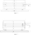
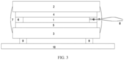
- FIG. 1 is a structural diagram of the rear-view mirror
- the rear-view mirror includes an electrochromic film 1, a first glass layer 2, a second glass layer 3, a first transparent adhesive layer 4, a second transparent adhesive layer 5 and a sealing structure layer.
- the first glass layer 2 and the second glass layer 3 are located on two faces of the electrochromic film 1 respectively, the first transparent adhesive layer 4 is located between the first glass layer 2 and the electrochromic film 1, the second transparent adhesive layer 5 is located between the second glass layer 3 and the electrochromic film 1, the sealing structure layer is located on edges of the first glass layer 2 and the second glass layer 3, the sealing structure layer, the first glass layer 2 and the second glass layer 3 form a sealing structure, and the electrochromic film 1 is sealed in the sealing structure.
- the sealing structure layer includes a sealing layer 6 and a structure layer 7.
- the sealing layer 6 is further connected to side faces of the first transparent adhesive layer 2, the electrochromic film 1, and the second transparent adhesive layer 3.
- the structure layer 7 is located on the side of the sealing layer 6 facing away from the electrochromic film 1.
- the electrochromic film 1 is further connected to an electrode 8 led out from the sealing structure layer.
- the rear-view mirror further includes two fixing strips 9 on the face of the second glass layer 3 facing away from the electrochromic film 1, where the fixing strips 9 fix the rear-view mirror on a platform 10.
- both the first transparent adhesive layer 4 and the second transparent adhesive layer 5 are the polyvinyl butyral (PVB), the first transparent adhesive layer 4 has a thickness of 0.76 mm, and the second transparent adhesive layer 5 has a thickness of 0.76 mm.
- the second glass layer 3 has a face bonded to the second transparent adhesive layer 5, where the face is coated with a reflective layer, and the reflective layer adjusts the specular reflectance of the second glass layer 3 to 99.9%.
- the sealing layer 6 is made of the butyl rubber and has a thickness of 1.8 mm.
- the structure layer 7 is made of the structural epoxy adhesive and has a thickness equal to or slightly greater than 1.8 mm. It suffices that the thickness of the structure layer 7 is not less than the thickness of the sealing layer 6 and not greater than the total thickness of the first glass layer 2, the first transparent adhesive layer 4, the electrochromic film 1, the second transparent adhesive layer 5, and the second glass layer 3.
- fixing strips 9 are double-sided foam tapes and the number of fixing strips 9 is two.
- a method for preparing the preceding rear-view mirror is further provided. The method includes steps described below.
- the electrochromic film 1 is well fixed, and the relative vibration and distortion are prevented.
- the electrochromic film changes the color stably during use, will not be affected by the mechanical vibration of the automobile, and the artificial external forces, mitigates the influence of the vibration on the rear-view mirror during the traveling of the vehicle, has the good waterproof performance and the excellent ability to block the gases, and prevents the internal device from failing because of the oxidation.
- the fixing strips better fix the whole rear-view mirror, mitigate the influence of the vibration on the whole mirror, and prevent the relative displacement of the whole mirror.
- the rear-view mirror provided in this embodiment is the same as the rear-view mirror in embodiment four except for features described below.
- the rear-view mirror in this embodiment differs from the rear-view mirror in embodiment four in that in the rear-view mirror provided in this embodiment, two sides of the electrochromic film 1 are narrower than the first transparent adhesive layer 4 and the second transparent adhesive layer 5, and the sides of the first transparent adhesive layer 4 and the second transparent adhesive layer 5 adhere to each other to enclose the electrochromic film 1 therein.
- Both the first transparent adhesive layer 4 and the second transparent adhesive layer 5 are films of ethylene-vinyl acetate (EVA) copolymers.
- EVA ethylene-vinyl acetate
- the first transparent adhesive layer 4 has a thickness of 0.38 mm
- the second transparent adhesive layer 5 has a thickness of 0.38 mm.
- the second glass layer 3 has a face bonded to the second transparent adhesive layer 5, where the face is coated with a reflective layer, and the reflective layer adjusts the specular reflectance of the second glass layer 3 to 80%.
- the sealing layer 6 is made of the silicone adhesive and has a thickness of 1.0 mm.
- the structure layer 7 is made of the structural epoxy adhesive and has a thickness of 1.0 mm.
- a fixing strip 9 is the double-sided foam tape.
- a method for preparing the preceding rear-view mirror is further provided. The method includes steps described below.
- the electrochromic film 1 is well fixed, and the relative vibration and distortion are prevented.
- the electrochromic film 1 changes the color stably during use, will not be affected by the mechanical vibration of the automobile, and the artificial external forces, mitigates the influence of the vibration on the rear-view mirror during the traveling of the vehicle, has the good waterproof performance and the excellent ability to block the gases, and prevents the internal device from failing because of the oxidation.
- the fixing strips better fix the whole rear-view mirror, mitigate the influence of the vibration on the whole mirror, and prevent the relative displacement of the whole mirror.
- the rear-view mirror provided in this embodiment is the same as the rear-view mirror in embodiment four except for features described below.
- the rear-view mirror in this embodiment differs from the rear-view mirror in embodiment four in that two sides of the electrochromic film 1 are narrower than the first transparent adhesive layer 4 and the second transparent adhesive layer 5, and the sealing layer 6 is located between the first transparent adhesive layer 4 and the second transparent adhesive layer 5 to seal sides of the electrochromic film 1.
- the first transparent adhesive layer 4 is the OCA and has a thickness of 0.1 mm.
- the second transparent adhesive layer 5 is the OCA and has a thickness of 0.1 mm.
- the second glass layer 3 has a face bonded to the second transparent adhesive layer 5, where the face is coated with a reflective layer, and the reflective layer adjusts the specular reflectance of the second glass layer 3 to 90%.
- the sealing layer 6 is made of the butyl rubber and has a thickness of 0.5 mm.
- the structure layer 7 is made of the structural silicone adhesive and has a thickness of 0.5 mm.
- the method includes steps described below.
- the electrochromic film 1 is well fixed, and the peripheral edges of the first transparent adhesive layer and the second transparent adhesive layer adhere to each other to seal the electrochromic film inside.
- the displacement between layers of the electrochromic film for example, the displacement between the electrolyte layer and the electrochromic layer, the displacement between the dielectric layer and the ion storage layer, and the like can be effectively avoided.
- the relative vibration and distortion are prevented.
- the electrochromic film changes the color stably during use, will not be affected by the mechanical vibration of the automobile, and the artificial external forces, mitigates the influence of the vibration on the rear-view mirror during the traveling of the vehicle, has the good waterproof performance and the excellent ability to block the gases, and prevents the internal device from failing because of the oxidation.
- the fixing strips better fix the whole rear-view mirror, mitigate the influence of the vibration on the whole mirror, and prevent the relative displacement of the whole mirror.
- the rear-view mirror provided in this embodiment is the same as the rear-view mirror in embodiment five except for features described below.
- the rear-view mirror in this embodiment differs from the rear-view mirror in embodiment five in that the first transparent adhesive layer 4 is the SCA and has a thickness of 0.2 mm, and the second transparent adhesive layer 5 is the SCA and has a thickness of 0.2 mm.
- the sealing layer 6 is made of the epoxy adhesive and has a thickness of 0.5 mm.
- the structure layer 7 is made of the structural silicone adhesive and has a thickness of 0.5 mm.
- a method for preparing the preceding rear-view mirror is further provided. The method includes steps described below.
- the electrochromic film 1 is well fixed, and the relative vibration and distortion are prevented.
- the electrochromic film changes the color stably during use, will not be affected by the mechanical vibration of the automobile, and the artificial external forces, mitigates the influence of the vibration on the rear-view mirror during the traveling of the vehicle, has the good waterproof performance and the excellent ability to block the gases, and prevents the internal device from failing because of the oxidation.
- the fixing strips better fix the whole rear-view mirror, mitigate the influence of the vibration on the whole mirror, and prevent the relative displacement of the whole mirror.
- the rear-view mirror provided in the comparative example is the same as the rear-view mirror in embodiment four except that the rear-view mirror provided in the comparative example does not have a sealing structure layer (that is, the sealant strip is not attached around the first glass layer during preparation, and operation in step 2 in embodiment four is not performed).
- the electrochromic film of the rear-view mirror provided in this comparative example shows a rapid decrease in performance due to water permeation, affecting the safety in use since there is no sealing structure layer formed by a sealing layer and a structure layer in the comparative example.
- the first glass layer and the second glass layer are displaced laterally and longitudinally due to an external force. Considering the strength of an adhesive force, a thin-film device with a weak adhesive force will fall off so that the rear-view mirror will fail.
- a waterproof test at 85 °C and 85 % RH is performed on the products in embodiments four to seven and the product in the comparative example for 1000 hours to determine whether the products are qualified.
- a test method and a criterion for determining whether the products are qualified are as follows: a constant temperature and humidity chamber is used to perform the test; a cobalt chloride paper for detecting a water content is used to take the place of the thin-film device; a specimen is stored at 85 °C and 85 % relative humidity for 1000 hours; the paper is taken out every 200 hours for observing whether the color of the paper in the specimen is changed; and a product is qualified if the paper is still blue and the product is unqualified if the paper becomes white or purplish-red.
- a waterproof test at 52 °C and 98 % RH is performed on the products in embodiments four to seven and the product in the comparative example for 1000 hours to determine whether the products are qualified.
- a test method and a criterion for determining whether the products are qualified are as follows: the constant temperature and humidity chamber is used to perform the test; the cobalt chloride paper for detecting the water content is used to take the place of the thin-film device; a specimen is stored at 52 °C and 98 % relative humidity for 1000 hours; the paper is taken out every 200 hours for observing whether the color of the paper in the specimen is changed; and a product is qualified if the paper is still blue and the product is unqualified if the paper becomes white or purplish-red.
- a 700 N tensile strength test is performed on the products in embodiments four to seven and the product in the comparative example as the characterization of the shock absorption performance.
- a test method and a criterion for determining whether the products are qualified are as follows: a tensile machine is used to apply a 700 N load to an outer side of the first glass layer 2 and an outer side of the second glass layer 3 for 10 s; and it is checked whether the glass layers of a specimen are cracked and there is a film falling off, a bubble, or a cracked edge in the specimen, and it is qualified if there is no change. Greater tensile strength of the rear-view mirror indicates that the relative displacement between the multiple layers of the rear-view mirror and even the direct detachment of a layer will not occur under the action of a relatively great external force. When used in automobiles, the rear-view mirrors with the greater tensile strength have better shock absorption performance.
- Table 1 Results of the Waterproof Test at 85 °C and 85 % RH Results of the Waterproof Test at 52 °C and 98 % RH Results of the 700 N Tensile Strength Test Embodiment four Qualified Qualified Qualified Embodiment five Qualified Qualified Qualified Embodiment six Qualified Qualified Qualified Embodiment seven Qualified Qualified Qualified Comparative example Unqualified (the paper becomes purplish-red.) Unqualified (the paper becomes purplish-red.) Unqualified (the film falls off and the specimen is divided into two halves.)
- the first transparent adhesive layer, the second transparent adhesive layer, and the sealing structure layer cooperate with each other, thereby preventing the relative vibration and distortion, producing a good shock adsorption effect for the electrochromic film, and having the water-proof performance.
- the fixing strips can better fix the whole rear-view mirror so that the influence of the vibration on the whole mirror can be mitigated, and the relative displacement of the whole mirror can be prevented.
- the specimen has no sealing structure layer and therefore has a poor shock absorption effect and does not have the waterproof performance.
Landscapes
- Physics & Mathematics (AREA)
- Nonlinear Science (AREA)
- Engineering & Computer Science (AREA)
- General Physics & Mathematics (AREA)
- Optics & Photonics (AREA)
- Chemical & Material Sciences (AREA)
- Crystallography & Structural Chemistry (AREA)
- Multimedia (AREA)
- Mechanical Engineering (AREA)
- Electrochromic Elements, Electrophoresis, Or Variable Reflection Or Absorption Elements (AREA)
Claims (11)
- Rückspiegel, umfassend eine elektrochrome Folie (1), eine erste Glasschicht (2), eine zweite Glasschicht (3), eine erste transparente Klebstoffschicht (4), eine zweite transparente Klebstoffschicht (5) und eine Versiegelungsstrukturschicht, wobeiSich die erste Glasschicht (2) und die zweite Glasschicht (3) jeweils auf beiden Seiten der elektrochromen Folie (1) befinden,die erste transparente Klebstoffschicht (4) zwischen der ersten Glasschicht (2) und der elektrochromen Folie (1) angeordnet ist,die zweite transparente Klebstoffschicht (5) zwischen der zweiten Glasschicht (3) und der elektrochromen Folie (1) angeordnet ist,die Versiegelungsstrukturschicht an Rändern der ersten Glasschicht (2) und der zweiten Glasschicht (3) angeordnet ist, wobei die Versiegelungsstrukturschicht, die erste Glasschicht (2) und die zweite Glasschicht (3) eine Versiegelungsstruktur bilden und die elektrochrome Folie (1) in der Versiegelungsstruktur versiegelt ist, unddie Versiegelungsstrukturschicht eine Versiegelungsschicht (6) und eine Strukturschicht (7) umfasst, wobei die Versiegelungsschicht (6) und die Strukturschicht (7) benachbart zueinander angeordnet sind und die Versiegelungsschicht (6) näher zur elektrochromen Folie (1) hin angeordnet ist als die Strukturschicht (7), dadurch gekennzeichnet, dassdie Versiegelungsschicht (6) zwischen der ersten Glasschicht (2) und der zweiten Glasschicht (3) angeordnet ist.
- Rückspiegel nach Anspruch 1, wobei ein Material der Versiegelungsschicht (6) mindestens eines der Materialien Silikonklebstoff, Butylkautschuk oder Epoxidklebstoff umfasst.
- Rückspiegel nach Anspruch 1, wobei ein Material der Strukturschicht (7) mindestens eines der Materialien struktureller Silikonklebstoff oder struktureller Epoxidklebstoff umfasst.
- Rückspiegel nach Anspruch 1, wobei die Versiegelungsschicht (6) an peripheren Seitenflächen der ersten transparenten Klebstoffschicht (4), der elektrochromen Folie (1) und der zweiten transparenten Klebstoffschicht (5) angeordnet ist.
- Rückspiegel nach Anspruch 1, wobei die Versiegelungsschicht (6) zwischen einer Kante der ersten transparenten Klebstoffschicht (4) und einer Kante der zweiten transparenten Klebstoffschicht (5) angeordnet ist und sich an einer peripheren Seitenfläche der elektrochromen Folie (1) befindet.
- Rückspiegel nach Anspruch 1, wobei eine Kante der ersten transparenten Klebstoffschicht (4) und eine Kante der zweiten transparenten Klebstoffschicht (5) miteinander verklebt sind, um eine Versiegelungsstruktur zu bilden, wobei die elektrochrome Folie (1) in der durch die erste transparente Klebstoffschicht (4) und die zweite transparente Klebstoffschicht (5) gebildeten Versiegelungsstruktur angeordnet ist und die Versiegelungsschicht (6) an peripheren Seitenflächen der ersten transparenten Klebstoffschicht (4) und der zweiten transparenten Klebstoffschicht (5) angeordnet ist.
- Rückspiegel nach Anspruch 1, wobei eine Dicke der Strukturschicht (7) nicht geringer ist als eine Dicke der Versiegelungsschicht (6) und nicht größer ist als eine Summe aus einer Dicke der ersten Glasschicht (2), einer Dicke der ersten transparenten Klebstoffschicht (4), einer Dicke der elektrochromen Folie (1), einer Dicke der zweiten transparenten Klebstoffschicht (5) und einer Dicke der zweiten Glasschicht (3).
- Rückspiegel nach Anspruch 1, wobei ein Material der ersten transparenten Klebstoffschicht (4) mindestens eines der Materialien optisch klarer Klebstoff, fester optisch klarer Klebstoff, Ethylen-Vinylacetat-Copolymer oder Polyvinylbutyral umfasst; und wobei ein Material der zweiten transparenten Klebstoffschicht (5) mindestens eines der Materialien optisch klarer Klebstoff, fester optisch klarer Klebstoff, Ethylen-Vinylacetat-Copolymer oder Polyvinylbutyral umfasst.
- Rückspiegel nach Anspruch 1, wobei eine der zweiten transparenten Klebstoffschicht (5) zugewandte Fläche der zweiten Glasschicht (3) mit einer reflektierenden Schicht beschichtet ist.
- Rückspiegel nach Anspruch 1, ferner umfassend eine Elektrode (8), die mit der elektrochromen Folie (1) verbunden und aus der Versiegelungsstrukturschicht herausgeführt ist.
- Rückspiegel nach Anspruch 1, ferner umfassend Befestigungsleisten (9), die auf einer von der elektrochromen Folie (1) abgewandten Fläche der zweiten Glasschicht (3) angeordnet sind, wobei die Befestigungsleisten (9) dazu ausgelegt sind, den Rückspiegel auf einer Plattform (10) zu befestigen, und wobei eine Anzahl der Befestigungsleisten (9) nicht weniger als eins beträgt.
Applications Claiming Priority (2)
| Application Number | Priority Date | Filing Date | Title |
|---|---|---|---|
| CN201911283125.9A CN110901540A (zh) | 2019-12-13 | 2019-12-13 | 一种后视镜 |
| PCT/CN2020/134745 WO2021115294A1 (zh) | 2019-12-13 | 2020-12-09 | 后视镜 |
Publications (4)
| Publication Number | Publication Date |
|---|---|
| EP4074548A1 EP4074548A1 (de) | 2022-10-19 |
| EP4074548A4 EP4074548A4 (de) | 2024-02-07 |
| EP4074548C0 EP4074548C0 (de) | 2025-05-28 |
| EP4074548B1 true EP4074548B1 (de) | 2025-05-28 |
Family
ID=69825442
Family Applications (1)
| Application Number | Title | Priority Date | Filing Date |
|---|---|---|---|
| EP20900524.8A Active EP4074548B1 (de) | 2019-12-13 | 2020-12-09 | Rückspiegel |
Country Status (4)
| Country | Link |
|---|---|
| US (1) | US12409780B2 (de) |
| EP (1) | EP4074548B1 (de) |
| CN (1) | CN110901540A (de) |
| WO (1) | WO2021115294A1 (de) |
Families Citing this family (6)
| Publication number | Priority date | Publication date | Assignee | Title |
|---|---|---|---|---|
| CN110901540A (zh) * | 2019-12-13 | 2020-03-24 | 深圳市光羿科技有限公司 | 一种后视镜 |
| CN114637150B (zh) | 2020-12-16 | 2023-10-20 | 深圳市光羿科技有限公司 | 一种电致变色器件 |
| EP4343417A4 (de) * | 2021-05-17 | 2025-05-28 | Hoya Lens Thailand Ltd. | Elektrochromes element und brillenglas |
| CN115729006A (zh) * | 2021-08-31 | 2023-03-03 | 深圳市光羿科技有限公司 | 一种电致变色器件及其制备方法和应用 |
| CN113625497B (zh) * | 2021-09-16 | 2024-06-18 | 苏州伯宇科技有限公司 | 一种电致变色镜片的贴合工艺及电致变色镜片 |
| CN118778296A (zh) * | 2024-08-08 | 2024-10-15 | 福耀玻璃工业集团股份有限公司 | 调光组件及其制备方法、车辆 |
Family Cites Families (18)
| Publication number | Priority date | Publication date | Assignee | Title |
|---|---|---|---|---|
| US5086351A (en) * | 1989-07-13 | 1992-02-04 | M&T Chemicals, Inc. | Electrochromic elements, materials for use in such element, processes for making such elements and such materials and use of such element in an electrochromic glass device |
| US20060158735A1 (en) * | 2004-02-20 | 2006-07-20 | Tonar William L | Electro-optic device having a self-cleaning hydrophilic coating |
| US7064882B2 (en) * | 2002-09-30 | 2006-06-20 | Gentex Corporation | Electrochromic devices having no positional offset between substrates |
| US7310177B2 (en) | 2002-09-20 | 2007-12-18 | Donnelly Corporation | Electro-optic reflective element assembly |
| TWI236985B (en) * | 2004-01-19 | 2005-08-01 | Exon Science Inc | Rearview mirror |
| US7706046B2 (en) * | 2004-06-08 | 2010-04-27 | Gentex Corporation | Rearview mirror element having a circuit mounted to the rear surface of the element |
| AU2008201373B1 (en) * | 2008-03-26 | 2009-07-23 | University Of South Australia | Processes for producing electrochromic substrates and electrochromic articles made therefrom |
| CN201607593U (zh) * | 2010-01-11 | 2010-10-13 | 大连东方科脉电子有限公司 | 一种染料液晶防眩目汽车后视镜 |
| CN102862337B (zh) * | 2012-10-15 | 2015-09-02 | 中航华东光电有限公司 | 一种光学膜组制作方法 |
| US9669764B2 (en) * | 2013-10-16 | 2017-06-06 | Magna Mirrors Of America, Inc. | Vehicular mirror reflective element with electrochromic film |
| CN104570535A (zh) * | 2013-10-24 | 2015-04-29 | 力光兴科技股份有限公司 | 电致变色汽车后视镜体结构及其制造方法 |
| US10520780B2 (en) * | 2016-12-21 | 2019-12-31 | Southwall Technologies Inc. | Electroactive device provided with a trilayer bus bar |
| CN207123692U (zh) * | 2017-06-29 | 2018-03-20 | 常州雅谱新材料有限公司 | 一种无位错电致变色防眩目外后视镜镜片 |
| CN107380072A (zh) * | 2017-07-27 | 2017-11-24 | 信利光电股份有限公司 | 一种电致变色后视镜结构 |
| US11092867B2 (en) * | 2017-12-29 | 2021-08-17 | Gentex Corporation | Polarized electrochromic device |
| EP3543780B1 (de) * | 2018-03-19 | 2020-08-12 | Oktopolymer Llc | Elektrochrome vorrichtung und verfahren zu deren herstellung |
| CN211567810U (zh) * | 2019-12-13 | 2020-09-25 | 深圳市光羿科技有限公司 | 一种后视镜 |
| CN110901540A (zh) * | 2019-12-13 | 2020-03-24 | 深圳市光羿科技有限公司 | 一种后视镜 |
-
2019
- 2019-12-13 CN CN201911283125.9A patent/CN110901540A/zh active Pending
-
2020
- 2020-12-09 WO PCT/CN2020/134745 patent/WO2021115294A1/zh not_active Ceased
- 2020-12-09 US US17/784,698 patent/US12409780B2/en active Active
- 2020-12-09 EP EP20900524.8A patent/EP4074548B1/de active Active
Also Published As
| Publication number | Publication date |
|---|---|
| US12409780B2 (en) | 2025-09-09 |
| CN110901540A (zh) | 2020-03-24 |
| EP4074548A1 (de) | 2022-10-19 |
| US20230021346A1 (en) | 2023-01-26 |
| EP4074548C0 (de) | 2025-05-28 |
| WO2021115294A1 (zh) | 2021-06-17 |
| EP4074548A4 (de) | 2024-02-07 |
Similar Documents
| Publication | Publication Date | Title |
|---|---|---|
| EP4074548B1 (de) | Rückspiegel | |
| EP3388403B1 (de) | Verbundglas | |
| EP4484157A1 (de) | Dimmanordnung und herstellungsverfahren dafür sowie fahrzeug | |
| EP2117050B1 (de) | Rückseitenschutzfolie für eine solarzelle und solarzellenmodul damit | |
| CN105473526B (zh) | 多层玻璃 | |
| US11119378B2 (en) | Dimming laminate and multiple glass | |
| US20160312523A1 (en) | Laminated glass | |
| EP2302447A1 (de) | Verfahren zur Herstelllung eines elektrochromen Sicherheitsglases | |
| US20090159117A1 (en) | Hot melt sealant containing desiccant for use in photovoltaic modules | |
| US20240009970A1 (en) | Laminated liquid crystal glazing and method for producing same | |
| JP2003050406A (ja) | エレクトロクロミック安全性ガラス品 | |
| CN217077465U (zh) | 封装胶膜及光伏组件 | |
| CN110010715B (zh) | 一种多层封装胶膜 | |
| CN211567810U (zh) | 一种后视镜 | |
| CN114597275B (zh) | 太阳能电池组件及其制造方法 | |
| WO2017142784A1 (en) | Improved electrical feed through holes for photovoltaic modules | |
| CN119562604A (zh) | 光伏组件及光伏组件的制备方法 | |
| WO2012165170A1 (ja) | 太陽電池用裏面保護シートとそれを備えた太陽電池モジュール | |
| US20250083418A1 (en) | Laminated glazing having a functional film | |
| CN115926641A (zh) | 一种支撑型封装胶膜 | |
| JPS615583A (ja) | 太陽電池モジユ−ル | |
| JPH10119184A (ja) | 透明積層体 | |
| JPH0617958B2 (ja) | エレクトロクロミック表示素子の製造方法 | |
| CN220044082U (zh) | 薄膜型太阳能电池的边缘封装结构 | |
| CN223711971U (zh) | 一种电致变色器件和终端产品 |
Legal Events
| Date | Code | Title | Description |
|---|---|---|---|
| STAA | Information on the status of an ep patent application or granted ep patent |
Free format text: STATUS: THE INTERNATIONAL PUBLICATION HAS BEEN MADE |
|
| PUAI | Public reference made under article 153(3) epc to a published international application that has entered the european phase |
Free format text: ORIGINAL CODE: 0009012 |
|
| STAA | Information on the status of an ep patent application or granted ep patent |
Free format text: STATUS: REQUEST FOR EXAMINATION WAS MADE |
|
| 17P | Request for examination filed |
Effective date: 20220601 |
|
| AK | Designated contracting states |
Kind code of ref document: A1 Designated state(s): AL AT BE BG CH CY CZ DE DK EE ES FI FR GB GR HR HU IE IS IT LI LT LU LV MC MK MT NL NO PL PT RO RS SE SI SK SM TR |
|
| DAV | Request for validation of the european patent (deleted) | ||
| DAX | Request for extension of the european patent (deleted) | ||
| A4 | Supplementary search report drawn up and despatched |
Effective date: 20240109 |
|
| RIC1 | Information provided on ipc code assigned before grant |
Ipc: G02F 1/153 20060101ALI20240103BHEP Ipc: B60R 1/08 20060101AFI20240103BHEP |
|
| GRAP | Despatch of communication of intention to grant a patent |
Free format text: ORIGINAL CODE: EPIDOSNIGR1 |
|
| STAA | Information on the status of an ep patent application or granted ep patent |
Free format text: STATUS: GRANT OF PATENT IS INTENDED |
|
| INTG | Intention to grant announced |
Effective date: 20241218 |
|
| GRAS | Grant fee paid |
Free format text: ORIGINAL CODE: EPIDOSNIGR3 |
|
| GRAA | (expected) grant |
Free format text: ORIGINAL CODE: 0009210 |
|
| STAA | Information on the status of an ep patent application or granted ep patent |
Free format text: STATUS: THE PATENT HAS BEEN GRANTED |
|
| AK | Designated contracting states |
Kind code of ref document: B1 Designated state(s): AL AT BE BG CH CY CZ DE DK EE ES FI FR GB GR HR HU IE IS IT LI LT LU LV MC MK MT NL NO PL PT RO RS SE SI SK SM TR |
|
| REG | Reference to a national code |
Ref country code: GB Ref legal event code: FG4D |
|
| REG | Reference to a national code |
Ref country code: CH Ref legal event code: EP |
|
| REG | Reference to a national code |
Ref country code: IE Ref legal event code: FG4D Ref country code: DE Ref legal event code: R096 Ref document number: 602020052117 Country of ref document: DE |
|
| U01 | Request for unitary effect filed |
Effective date: 20250625 |
|
| U07 | Unitary effect registered |
Designated state(s): AT BE BG DE DK EE FI FR IT LT LU LV MT NL PT RO SE SI Effective date: 20250701 |
|
| PG25 | Lapsed in a contracting state [announced via postgrant information from national office to epo] |
Ref country code: ES Free format text: LAPSE BECAUSE OF FAILURE TO SUBMIT A TRANSLATION OF THE DESCRIPTION OR TO PAY THE FEE WITHIN THE PRESCRIBED TIME-LIMIT Effective date: 20250528 |
|
| PG25 | Lapsed in a contracting state [announced via postgrant information from national office to epo] |
Ref country code: NO Free format text: LAPSE BECAUSE OF FAILURE TO SUBMIT A TRANSLATION OF THE DESCRIPTION OR TO PAY THE FEE WITHIN THE PRESCRIBED TIME-LIMIT Effective date: 20250828 Ref country code: GR Free format text: LAPSE BECAUSE OF FAILURE TO SUBMIT A TRANSLATION OF THE DESCRIPTION OR TO PAY THE FEE WITHIN THE PRESCRIBED TIME-LIMIT Effective date: 20250829 |
|
| PG25 | Lapsed in a contracting state [announced via postgrant information from national office to epo] |
Ref country code: PL Free format text: LAPSE BECAUSE OF FAILURE TO SUBMIT A TRANSLATION OF THE DESCRIPTION OR TO PAY THE FEE WITHIN THE PRESCRIBED TIME-LIMIT Effective date: 20250528 |
|
| PG25 | Lapsed in a contracting state [announced via postgrant information from national office to epo] |
Ref country code: HR Free format text: LAPSE BECAUSE OF FAILURE TO SUBMIT A TRANSLATION OF THE DESCRIPTION OR TO PAY THE FEE WITHIN THE PRESCRIBED TIME-LIMIT Effective date: 20250528 |
|
| PG25 | Lapsed in a contracting state [announced via postgrant information from national office to epo] |
Ref country code: RS Free format text: LAPSE BECAUSE OF FAILURE TO SUBMIT A TRANSLATION OF THE DESCRIPTION OR TO PAY THE FEE WITHIN THE PRESCRIBED TIME-LIMIT Effective date: 20250828 |
|
| PG25 | Lapsed in a contracting state [announced via postgrant information from national office to epo] |
Ref country code: IS Free format text: LAPSE BECAUSE OF FAILURE TO SUBMIT A TRANSLATION OF THE DESCRIPTION OR TO PAY THE FEE WITHIN THE PRESCRIBED TIME-LIMIT Effective date: 20250928 |
|
| PGFP | Annual fee paid to national office [announced via postgrant information from national office to epo] |
Ref country code: GB Payment date: 20251219 Year of fee payment: 6 |
|
| PG25 | Lapsed in a contracting state [announced via postgrant information from national office to epo] |
Ref country code: SM Free format text: LAPSE BECAUSE OF FAILURE TO SUBMIT A TRANSLATION OF THE DESCRIPTION OR TO PAY THE FEE WITHIN THE PRESCRIBED TIME-LIMIT Effective date: 20250528 |
|
| PG25 | Lapsed in a contracting state [announced via postgrant information from national office to epo] |
Ref country code: CZ Free format text: LAPSE BECAUSE OF FAILURE TO SUBMIT A TRANSLATION OF THE DESCRIPTION OR TO PAY THE FEE WITHIN THE PRESCRIBED TIME-LIMIT Effective date: 20250528 |
|
| PG25 | Lapsed in a contracting state [announced via postgrant information from national office to epo] |
Ref country code: SK Free format text: LAPSE BECAUSE OF FAILURE TO SUBMIT A TRANSLATION OF THE DESCRIPTION OR TO PAY THE FEE WITHIN THE PRESCRIBED TIME-LIMIT Effective date: 20250528 |
|
| U20 | Renewal fee for the european patent with unitary effect paid |
Year of fee payment: 6 Effective date: 20251230 |
|
| PLBE | No opposition filed within time limit |
Free format text: ORIGINAL CODE: 0009261 |
|
| STAA | Information on the status of an ep patent application or granted ep patent |
Free format text: STATUS: NO OPPOSITION FILED WITHIN TIME LIMIT |
|
| REG | Reference to a national code |
Ref country code: CH Ref legal event code: L10 Free format text: ST27 STATUS EVENT CODE: U-0-0-L10-L00 (AS PROVIDED BY THE NATIONAL OFFICE) Effective date: 20260409 |