EP4074418A1 - Electrode catalyst for fuel cell, electrode catalyst layer for fuel cell, membrane/electrode assembly, and fuel cell - Google Patents
Electrode catalyst for fuel cell, electrode catalyst layer for fuel cell, membrane/electrode assembly, and fuel cell Download PDFInfo
- Publication number
- EP4074418A1 EP4074418A1 EP20886178.1A EP20886178A EP4074418A1 EP 4074418 A1 EP4074418 A1 EP 4074418A1 EP 20886178 A EP20886178 A EP 20886178A EP 4074418 A1 EP4074418 A1 EP 4074418A1
- Authority
- EP
- European Patent Office
- Prior art keywords
- electrode
- electrode catalyst
- equal
- fuel battery
- catalyst
- Prior art date
- Legal status (The legal status is an assumption and is not a legal conclusion. Google has not performed a legal analysis and makes no representation as to the accuracy of the status listed.)
- Pending
Links
- 239000003054 catalyst Substances 0.000 title claims abstract description 285
- 239000000446 fuel Substances 0.000 title claims abstract description 127
- 239000012528 membrane Substances 0.000 title claims description 33
- 239000013335 mesoporous material Substances 0.000 claims abstract description 101
- 239000002923 metal particle Substances 0.000 claims abstract description 79
- 238000000034 method Methods 0.000 claims abstract description 24
- 238000004438 BET method Methods 0.000 claims abstract description 12
- 238000000696 nitrogen adsorption--desorption isotherm Methods 0.000 claims abstract description 12
- 239000007789 gas Substances 0.000 claims description 38
- 229920000554 ionomer Polymers 0.000 claims description 38
- 239000005518 polymer electrolyte Substances 0.000 claims description 31
- 238000009792 diffusion process Methods 0.000 claims description 26
- OKTJSMMVPCPJKN-UHFFFAOYSA-N Carbon Chemical compound [C] OKTJSMMVPCPJKN-UHFFFAOYSA-N 0.000 claims description 20
- 239000006229 carbon black Substances 0.000 claims description 11
- 239000002041 carbon nanotube Substances 0.000 claims description 10
- 229910021393 carbon nanotube Inorganic materials 0.000 claims description 10
- 239000010410 layer Substances 0.000 description 103
- 230000000694 effects Effects 0.000 description 40
- 230000006866 deterioration Effects 0.000 description 29
- VNWKTOKETHGBQD-UHFFFAOYSA-N methane Chemical compound C VNWKTOKETHGBQD-UHFFFAOYSA-N 0.000 description 27
- 239000011148 porous material Substances 0.000 description 25
- 230000004048 modification Effects 0.000 description 17
- 238000012986 modification Methods 0.000 description 17
- 239000002245 particle Substances 0.000 description 17
- XLYOFNOQVPJJNP-UHFFFAOYSA-N water Substances O XLYOFNOQVPJJNP-UHFFFAOYSA-N 0.000 description 17
- BASFCYQUMIYNBI-UHFFFAOYSA-N platinum Chemical compound [Pt] BASFCYQUMIYNBI-UHFFFAOYSA-N 0.000 description 13
- 238000010248 power generation Methods 0.000 description 13
- 239000011347 resin Substances 0.000 description 13
- 229920005989 resin Polymers 0.000 description 13
- 238000010298 pulverizing process Methods 0.000 description 12
- IJGRMHOSHXDMSA-UHFFFAOYSA-N Atomic nitrogen Chemical compound N#N IJGRMHOSHXDMSA-UHFFFAOYSA-N 0.000 description 11
- 230000000052 comparative effect Effects 0.000 description 11
- LFQSCWFLJHTTHZ-UHFFFAOYSA-N Ethanol Chemical compound CCO LFQSCWFLJHTTHZ-UHFFFAOYSA-N 0.000 description 10
- MCMNRKCIXSYSNV-UHFFFAOYSA-N Zirconium dioxide Chemical compound O=[Zr]=O MCMNRKCIXSYSNV-UHFFFAOYSA-N 0.000 description 10
- 239000011324 bead Substances 0.000 description 9
- 229910052799 carbon Inorganic materials 0.000 description 8
- 238000005342 ion exchange Methods 0.000 description 8
- 230000002776 aggregation Effects 0.000 description 7
- 238000004220 aggregation Methods 0.000 description 7
- 239000003575 carbonaceous material Substances 0.000 description 6
- 238000006243 chemical reaction Methods 0.000 description 6
- 238000009826 distribution Methods 0.000 description 6
- 239000003273 ketjen black Substances 0.000 description 5
- 229910052757 nitrogen Inorganic materials 0.000 description 5
- 229910052697 platinum Inorganic materials 0.000 description 5
- 239000002002 slurry Substances 0.000 description 5
- 238000003756 stirring Methods 0.000 description 5
- UFHFLCQGNIYNRP-UHFFFAOYSA-N Hydrogen Chemical compound [H][H] UFHFLCQGNIYNRP-UHFFFAOYSA-N 0.000 description 4
- 239000010408 film Substances 0.000 description 4
- 239000001257 hydrogen Substances 0.000 description 4
- 229910052739 hydrogen Inorganic materials 0.000 description 4
- 239000007788 liquid Substances 0.000 description 4
- 229910052751 metal Inorganic materials 0.000 description 4
- 239000002184 metal Substances 0.000 description 4
- 239000012046 mixed solvent Substances 0.000 description 4
- 230000002940 repellent Effects 0.000 description 4
- 239000005871 repellent Substances 0.000 description 4
- 239000007787 solid Substances 0.000 description 4
- KDLHZDBZIXYQEI-UHFFFAOYSA-N Palladium Chemical compound [Pd] KDLHZDBZIXYQEI-UHFFFAOYSA-N 0.000 description 3
- QVGXLLKOCUKJST-UHFFFAOYSA-N atomic oxygen Chemical compound [O] QVGXLLKOCUKJST-UHFFFAOYSA-N 0.000 description 3
- 239000002737 fuel gas Substances 0.000 description 3
- 239000003456 ion exchange resin Substances 0.000 description 3
- 229920003303 ion-exchange polymer Polymers 0.000 description 3
- 239000000463 material Substances 0.000 description 3
- 239000007800 oxidant agent Substances 0.000 description 3
- 230000001590 oxidative effect Effects 0.000 description 3
- 239000001301 oxygen Substances 0.000 description 3
- 229910052760 oxygen Inorganic materials 0.000 description 3
- 230000035699 permeability Effects 0.000 description 3
- 239000002904 solvent Substances 0.000 description 3
- 238000001179 sorption measurement Methods 0.000 description 3
- 238000001132 ultrasonic dispersion Methods 0.000 description 3
- NWUYHJFMYQTDRP-UHFFFAOYSA-N 1,2-bis(ethenyl)benzene;1-ethenyl-2-ethylbenzene;styrene Chemical compound C=CC1=CC=CC=C1.CCC1=CC=CC=C1C=C.C=CC1=CC=CC=C1C=C NWUYHJFMYQTDRP-UHFFFAOYSA-N 0.000 description 2
- 229920000049 Carbon (fiber) Polymers 0.000 description 2
- 238000003775 Density Functional Theory Methods 0.000 description 2
- 229920000557 Nafion® Polymers 0.000 description 2
- XUIMIQQOPSSXEZ-UHFFFAOYSA-N Silicon Chemical compound [Si] XUIMIQQOPSSXEZ-UHFFFAOYSA-N 0.000 description 2
- 230000004888 barrier function Effects 0.000 description 2
- 239000004917 carbon fiber Substances 0.000 description 2
- 239000004020 conductor Substances 0.000 description 2
- 230000001186 cumulative effect Effects 0.000 description 2
- 239000006185 dispersion Substances 0.000 description 2
- 238000001035 drying Methods 0.000 description 2
- 238000003487 electrochemical reaction Methods 0.000 description 2
- UQSQSQZYBQSBJZ-UHFFFAOYSA-N fluorosulfonic acid Chemical compound OS(F)(=O)=O UQSQSQZYBQSBJZ-UHFFFAOYSA-N 0.000 description 2
- 239000010931 gold Substances 0.000 description 2
- 230000006872 improvement Effects 0.000 description 2
- 238000004519 manufacturing process Methods 0.000 description 2
- 238000005259 measurement Methods 0.000 description 2
- 239000004570 mortar (masonry) Substances 0.000 description 2
- 229920001343 polytetrafluoroethylene Polymers 0.000 description 2
- 239000004810 polytetrafluoroethylene Substances 0.000 description 2
- 238000006479 redox reaction Methods 0.000 description 2
- 229910052710 silicon Inorganic materials 0.000 description 2
- 239000010703 silicon Substances 0.000 description 2
- 239000007921 spray Substances 0.000 description 2
- 230000008961 swelling Effects 0.000 description 2
- 239000013032 Hydrocarbon resin Substances 0.000 description 1
- 241000282320 Panthera leo Species 0.000 description 1
- KJTLSVCANCCWHF-UHFFFAOYSA-N Ruthenium Chemical compound [Ru] KJTLSVCANCCWHF-UHFFFAOYSA-N 0.000 description 1
- BQCADISMDOOEFD-UHFFFAOYSA-N Silver Chemical compound [Ag] BQCADISMDOOEFD-UHFFFAOYSA-N 0.000 description 1
- ATJFFYVFTNAWJD-UHFFFAOYSA-N Tin Chemical compound [Sn] ATJFFYVFTNAWJD-UHFFFAOYSA-N 0.000 description 1
- RTAQQCXQSZGOHL-UHFFFAOYSA-N Titanium Chemical compound [Ti] RTAQQCXQSZGOHL-UHFFFAOYSA-N 0.000 description 1
- QCWXUUIWCKQGHC-UHFFFAOYSA-N Zirconium Chemical compound [Zr] QCWXUUIWCKQGHC-UHFFFAOYSA-N 0.000 description 1
- 239000006230 acetylene black Substances 0.000 description 1
- 230000009471 action Effects 0.000 description 1
- 229910045601 alloy Inorganic materials 0.000 description 1
- 239000000956 alloy Substances 0.000 description 1
- 229910052782 aluminium Inorganic materials 0.000 description 1
- XAGFODPZIPBFFR-UHFFFAOYSA-N aluminium Chemical compound [Al] XAGFODPZIPBFFR-UHFFFAOYSA-N 0.000 description 1
- 238000004458 analytical method Methods 0.000 description 1
- 239000012298 atmosphere Substances 0.000 description 1
- 230000015572 biosynthetic process Effects 0.000 description 1
- 230000008859 change Effects 0.000 description 1
- 238000004891 communication Methods 0.000 description 1
- 239000000470 constituent Substances 0.000 description 1
- 238000001816 cooling Methods 0.000 description 1
- 238000013461 design Methods 0.000 description 1
- 229910001873 dinitrogen Inorganic materials 0.000 description 1
- 230000002708 enhancing effect Effects 0.000 description 1
- 238000011156 evaluation Methods 0.000 description 1
- 239000004744 fabric Substances 0.000 description 1
- 238000001914 filtration Methods 0.000 description 1
- PCHJSUWPFVWCPO-UHFFFAOYSA-N gold Chemical compound [Au] PCHJSUWPFVWCPO-UHFFFAOYSA-N 0.000 description 1
- 229910052737 gold Inorganic materials 0.000 description 1
- 238000010438 heat treatment Methods 0.000 description 1
- 229920006270 hydrocarbon resin Polymers 0.000 description 1
- 238000011065 in-situ storage Methods 0.000 description 1
- 229910052741 iridium Inorganic materials 0.000 description 1
- GKOZUEZYRPOHIO-UHFFFAOYSA-N iridium atom Chemical compound [Ir] GKOZUEZYRPOHIO-UHFFFAOYSA-N 0.000 description 1
- 229910052758 niobium Inorganic materials 0.000 description 1
- 239000010955 niobium Substances 0.000 description 1
- GUCVJGMIXFAOAE-UHFFFAOYSA-N niobium atom Chemical compound [Nb] GUCVJGMIXFAOAE-UHFFFAOYSA-N 0.000 description 1
- UYXRCZUOJAYSQR-UHFFFAOYSA-N nitric acid;platinum Chemical compound [Pt].O[N+]([O-])=O UYXRCZUOJAYSQR-UHFFFAOYSA-N 0.000 description 1
- 239000012299 nitrogen atmosphere Substances 0.000 description 1
- 229910052763 palladium Inorganic materials 0.000 description 1
- 229920000642 polymer Polymers 0.000 description 1
- 229920005597 polymer membrane Polymers 0.000 description 1
- -1 polytetrafluoroethylene Polymers 0.000 description 1
- 229910052707 ruthenium Inorganic materials 0.000 description 1
- 229910052709 silver Inorganic materials 0.000 description 1
- 239000004332 silver Substances 0.000 description 1
- 239000002356 single layer Substances 0.000 description 1
- 229910052715 tantalum Inorganic materials 0.000 description 1
- GUVRBAGPIYLISA-UHFFFAOYSA-N tantalum atom Chemical compound [Ta] GUVRBAGPIYLISA-UHFFFAOYSA-N 0.000 description 1
- 239000010409 thin film Substances 0.000 description 1
- 229910052718 tin Inorganic materials 0.000 description 1
- 239000011135 tin Substances 0.000 description 1
- 229910052719 titanium Inorganic materials 0.000 description 1
- 239000010936 titanium Substances 0.000 description 1
- 238000012546 transfer Methods 0.000 description 1
- 238000005406 washing Methods 0.000 description 1
- 229910052726 zirconium Inorganic materials 0.000 description 1
Images


Classifications
-
- H—ELECTRICITY
- H01—ELECTRIC ELEMENTS
- H01M—PROCESSES OR MEANS, e.g. BATTERIES, FOR THE DIRECT CONVERSION OF CHEMICAL ENERGY INTO ELECTRICAL ENERGY
- H01M4/00—Electrodes
- H01M4/86—Inert electrodes with catalytic activity, e.g. for fuel cells
- H01M4/90—Selection of catalytic material
- H01M4/9075—Catalytic material supported on carriers, e.g. powder carriers
- H01M4/9083—Catalytic material supported on carriers, e.g. powder carriers on carbon or graphite
-
- B01J35/618—
-
- B01J35/647—
-
- H—ELECTRICITY
- H01—ELECTRIC ELEMENTS
- H01M—PROCESSES OR MEANS, e.g. BATTERIES, FOR THE DIRECT CONVERSION OF CHEMICAL ENERGY INTO ELECTRICAL ENERGY
- H01M4/00—Electrodes
- H01M4/86—Inert electrodes with catalytic activity, e.g. for fuel cells
- H01M4/8605—Porous electrodes
-
- H—ELECTRICITY
- H01—ELECTRIC ELEMENTS
- H01M—PROCESSES OR MEANS, e.g. BATTERIES, FOR THE DIRECT CONVERSION OF CHEMICAL ENERGY INTO ELECTRICAL ENERGY
- H01M4/00—Electrodes
- H01M4/86—Inert electrodes with catalytic activity, e.g. for fuel cells
- H01M4/8605—Porous electrodes
- H01M4/8621—Porous electrodes containing only metallic or ceramic material, e.g. made by sintering or sputtering
-
- H—ELECTRICITY
- H01—ELECTRIC ELEMENTS
- H01M—PROCESSES OR MEANS, e.g. BATTERIES, FOR THE DIRECT CONVERSION OF CHEMICAL ENERGY INTO ELECTRICAL ENERGY
- H01M4/00—Electrodes
- H01M4/86—Inert electrodes with catalytic activity, e.g. for fuel cells
- H01M4/8647—Inert electrodes with catalytic activity, e.g. for fuel cells consisting of more than one material, e.g. consisting of composites
- H01M4/8657—Inert electrodes with catalytic activity, e.g. for fuel cells consisting of more than one material, e.g. consisting of composites layered
-
- H—ELECTRICITY
- H01—ELECTRIC ELEMENTS
- H01M—PROCESSES OR MEANS, e.g. BATTERIES, FOR THE DIRECT CONVERSION OF CHEMICAL ENERGY INTO ELECTRICAL ENERGY
- H01M4/00—Electrodes
- H01M4/86—Inert electrodes with catalytic activity, e.g. for fuel cells
- H01M4/90—Selection of catalytic material
- H01M4/92—Metals of platinum group
- H01M4/925—Metals of platinum group supported on carriers, e.g. powder carriers
- H01M4/926—Metals of platinum group supported on carriers, e.g. powder carriers on carbon or graphite
-
- H—ELECTRICITY
- H01—ELECTRIC ELEMENTS
- H01M—PROCESSES OR MEANS, e.g. BATTERIES, FOR THE DIRECT CONVERSION OF CHEMICAL ENERGY INTO ELECTRICAL ENERGY
- H01M8/00—Fuel cells; Manufacture thereof
- H01M8/10—Fuel cells with solid electrolytes
-
- H—ELECTRICITY
- H01—ELECTRIC ELEMENTS
- H01M—PROCESSES OR MEANS, e.g. BATTERIES, FOR THE DIRECT CONVERSION OF CHEMICAL ENERGY INTO ELECTRICAL ENERGY
- H01M8/00—Fuel cells; Manufacture thereof
- H01M8/10—Fuel cells with solid electrolytes
- H01M8/1004—Fuel cells with solid electrolytes characterised by membrane-electrode assemblies [MEA]
-
- H—ELECTRICITY
- H01—ELECTRIC ELEMENTS
- H01M—PROCESSES OR MEANS, e.g. BATTERIES, FOR THE DIRECT CONVERSION OF CHEMICAL ENERGY INTO ELECTRICAL ENERGY
- H01M8/00—Fuel cells; Manufacture thereof
- H01M8/10—Fuel cells with solid electrolytes
- H01M2008/1095—Fuel cells with polymeric electrolytes
-
- H—ELECTRICITY
- H01—ELECTRIC ELEMENTS
- H01M—PROCESSES OR MEANS, e.g. BATTERIES, FOR THE DIRECT CONVERSION OF CHEMICAL ENERGY INTO ELECTRICAL ENERGY
- H01M4/00—Electrodes
- H01M4/86—Inert electrodes with catalytic activity, e.g. for fuel cells
- H01M4/90—Selection of catalytic material
- H01M4/92—Metals of platinum group
- H01M4/921—Alloys or mixtures with metallic elements
-
- Y—GENERAL TAGGING OF NEW TECHNOLOGICAL DEVELOPMENTS; GENERAL TAGGING OF CROSS-SECTIONAL TECHNOLOGIES SPANNING OVER SEVERAL SECTIONS OF THE IPC; TECHNICAL SUBJECTS COVERED BY FORMER USPC CROSS-REFERENCE ART COLLECTIONS [XRACs] AND DIGESTS
- Y02—TECHNOLOGIES OR APPLICATIONS FOR MITIGATION OR ADAPTATION AGAINST CLIMATE CHANGE
- Y02E—REDUCTION OF GREENHOUSE GAS [GHG] EMISSIONS, RELATED TO ENERGY GENERATION, TRANSMISSION OR DISTRIBUTION
- Y02E60/00—Enabling technologies; Technologies with a potential or indirect contribution to GHG emissions mitigation
- Y02E60/30—Hydrogen technology
- Y02E60/50—Fuel cells
Definitions
- the present disclosure relates to an electrode catalyst for a fuel battery, an electrode catalyst layer of a fuel battery, a membrane-electrode assembly, and a fuel battery.
- a solid polymer fuel battery including a proton-conductive solid polymer membrane includes a membrane-electrode assembly for subjecting hydrogencontaining fuel gas and oxygen-containing oxidant gas to an electrochemical reaction (a power generation reaction).
- an electrode catalyst layer constituting the membrane-electrode assembly is formed by applying a catalyst paste to a polymer electrolyte membrane or another such base material and thereafter performing drying.
- This catalyst paste is formed by dispersing a catalyst and a polymer electrolyte having proton conductivity (hereafter referred to as an "ionomer") in a solvent such as water or an alcohol.
- a catalyst metal such as platinum is supported on a conductive material such as carbon black.
- catalyst metal particles are supported in a carrier formed of mesoporous carbon.
- the present disclosure has been made in light of the problem described above and has an object to provide an electrode catalyst for a fuel battery, an electrode catalyst layer of a fuel battery, a membrane-electrode assembly, and a fuel battery that are capable of reducing the deterioration of the catalyst activity to a greater extent than in the related art.
- an electrode catalyst for a fuel battery includes a mesoporous material and catalyst metal particles supported at least in the mesoporous material.
- the mesoporous material before supporting the catalyst metal particles, has mesopores having a mode radius of greater than or equal to 1 nm and less than or equal to 25 nm and has a value of greater than 0.90, the value being determined by dividing a specific surface area S 1-25 (m 2 /g) of the mesopores obtained by analyzing a nitrogen adsorption-desorption isotherm according to a BJH method, the mesopores having a radius of greater than or equal to 1 nm and less than or equal to 25 nm, by a BET specific surface area (m 2 /g) evaluated according to a BET method.
- an electrode catalyst layer of a fuel battery includes the electrode catalyst for a fuel battery and an ionomer.
- the electrode catalyst for a fuel battery includes a mesoporous material and catalyst metal particles supported at least in the mesoporous material.
- the mesoporous material has mesopores having a mode radius of greater than or equal to 1 nm and less than or equal to 25 nm and has a value of greater than 0.90, the value being determined by dividing a specific surface area S 1-25 (m 2 /g) of the mesopores obtained by analyzing a nitrogen adsorption-desorption isotherm according to a BJH method, the mesopores having a radius of greater than or equal to 1 nm and less than or equal to 25 nm, by a BET specific surface area (m 2 /g) evaluated according to a BET method.
- a membrane-electrode assembly includes a polymer electrolyte membrane; and a fuel electrode and an air electrode respectively disposed on both main surfaces of the polymer electrolyte membrane, the fuel electrode and the air electrode each including an electrode catalyst layer and a gas diffusion layer.
- at least the electrode catalyst layer of the air electrode includes the electrode catalyst layer of a fuel battery including the electrode catalyst for a fuel battery and an ionomer.
- the electrode catalyst for a fuel battery includes a mesoporous material and catalyst metal particles supported at least in the mesoporous material.
- the mesoporous material has mesopores having a mode radius of greater than or equal to 1 nm and less than or equal to 25 nm and has a value of greater than 0.90, the value being determined by dividing a specific surface area S 1-25 (m 2 /g) of the mesopores obtained by analyzing a nitrogen adsorption-desorption isotherm according to a BJH method, the mesopores having a radius of greater than or equal to 1 nm and less than or equal to 25 nm, by a BET specific surface area (m 2 /g) evaluated according to a BET method.
- one aspect of a fuel battery according to the present disclosure includes the membrane-electrode assembly including a polymer electrolyte membrane; and a fuel electrode and an air electrode respectively disposed on both main surfaces of the polymer electrolyte membrane, the fuel electrode and the air electrode each including an electrode catalyst layer and a gas diffusion layer.
- the electrode catalyst layer of the air electrode includes the electrode catalyst layer of a fuel battery including the electrode catalyst for a fuel battery and an ionomer.
- the electrode catalyst for a fuel battery includes a mesoporous material and catalyst metal particles supported at least in the mesoporous material.
- the mesoporous material has mesopores having a mode radius of greater than or equal to 1 nm and less than or equal to 25 nm and has a value of greater than 0.90, the value being determined by dividing a specific surface area S 1-25 (m 2 /g) of the mesopores obtained by analyzing a nitrogen adsorption-desorption isotherm according to a BJH method, the mesopores having a radius of greater than or equal to 1 nm and less than or equal to 25 nm, by a BET specific surface area (m 2 /g) evaluated according to a BET method.
- the present disclosure has an effect where the electrode catalyst for a fuel battery, the electrode catalyst layer of a fuel battery, the membrane-electrode assembly, and the fuel battery are capable of reducing the deterioration of the catalyst activity to a greater extent than in the related art.
- the present inventors have repeatedly conducted intensive studies on the deterioration of the catalyst activity in the existing techniques disclosed in PTL 1 to 3. As a result, the inventors have focused on the fact that the ratio of the surface area of mesopores to the whole surface area of a mesoporous carbon carrier contributes to the deterioration of the catalyst activity of catalyst metal particles that is caused by an ionomer.
- the inventors have found that the deterioration of the catalyst activity is reduced by, before a mesoporous material supports catalyst metal particles, making the mesoporous material have a value of greater than 0.90, the value being determined by dividing a specific surface area S 1-25 (m 2 /g) of mesopores obtained by analysis according to a BJH method, the mesopores having a radius of greater than or equal to 1 nm and less than or equal to 25 nm, by a BET specific surface area (m 2 /g) evaluated according to a BET method.
- the present disclosure has been made based on this knowledge. Accordingly, the present disclosure specifically provides the aspects described below.
- An electrode catalyst for a fuel battery includes a mesoporous material and catalyst metal particles supported at least in the mesoporous material, where, before supporting the catalyst metal particles, the mesoporous material may have mesopores having a mode radius of greater than or equal to 1 nm and less than or equal to 25 nm and may have a value of greater than 0.90, the value being determined by dividing a specific surface area S 1-25 (m 2 /g) of the mesopores obtained by analyzing a nitrogen adsorption-desorption isotherm according to a BJH method, the mesopores having a radius of greater than or equal to 1 nm and less than or equal to 25 nm, by a BET specific surface area (m 2 /g) evaluated according to a BET method.
- catalyst metal particles can be supported in the mesopores of the mesoporous material. Furthermore, for example, even when an ionomer is in contact with the electrode catalyst, because the ionomer is less likely to enter the mesopores, the surface area of the catalyst metal particles covered with the ionomer can be reduced. Thus, the deterioration of the catalyst activity of the electrode catalyst due to the covering of the catalyst metal particles with the ionomer can be reduced.
- the mesopores of the mesoporous material may have a mode radius of greater than 1.65 nm.
- the BET specific surface area of the mesoporous material may be greater than or equal to 1500 (m 2 /g). Aggregation of the catalyst metal particles supported in the mesoporous material is reduced to a greater extent in the case of the mesoporous material having a BET specific surface area of greater than or equal to 1500 (m 2 /g) than in the case of a mesoporous material having a BET specific surface area of less than 1500 (m 2 /g). Thus, the decrease in the specific surface area of the catalyst metal particles due to aggregation is reduced, and accordingly, the deterioration of the catalyst activity of the electrode catalyst can be reduced.
- the catalyst metal particles supported in the mesopores may be greater than or equal to 0.90. According to this structure, for example, even when an ionomer is in contact with the electrode catalyst, the deterioration of the catalyst activity of the electrode catalyst due to the covering of the catalyst metal particles with the ionomer can be reduced.
- An electrode catalyst layer of a fuel battery according to a fifth aspect of the present disclosure may include at least the electrode catalyst for a fuel battery according to any one of the first to the fourth aspects and at least an ionomer. According to this structure, because the deterioration of the catalyst activity of the electrode catalyst due to the covering of the catalyst metal particles with the ionomer is reduced, the deterioration of the catalyst activity of the electrode catalyst layer due to the ionomer can be prevented or reduced.
- An electrode catalyst layer of a fuel battery according to a sixth aspect of the present disclosure in the fifth aspect, may include at least one of carbon black or carbon nanotubes.
- the drainage properties of the electrode catalyst layer is enhanced, and the deterioration of the catalyst activity of and the gas diffusivity in the electrode catalyst layer due to water can be reduced.
- the electrical resistance between the mesoporous material particles can be reduced.
- a membrane-electrode assembly may include a polymer electrolyte membrane; and a fuel electrode and an air electrode respectively disposed on both main surfaces of the polymer electrolyte membrane, the fuel electrode and the air electrode each including an electrode catalyst layer and a gas diffusion layer, where at least the electrode catalyst layer of the air electrode may include the electrode catalyst layer of a fuel battery according to the fifth or the sixth aspect.
- a fuel battery according to an eighth aspect of the present disclosure may include the membrane-electrode assembly according to the seventh aspect. According to this structure, because the deterioration of the catalyst activity of the membrane-electrode assembly is reduced, the deterioration of the catalyst activity of the fuel battery can be reduced.
- an electrode catalyst 1 for a fuel battery includes a mesoporous material 2 and catalyst metal particles 3 supported at least in the mesoporous material 2.
- the mesoporous material 2 is formed of a porous material having many mesopores 4 and is a carrier in which the catalyst metal particles 3 are supported.
- the mesoporous material 2 has, for example a particle shape, but is not limited thereto.
- the average particle diameter of the mesoporous material 2 is, for example, greater than or equal to 200 nm.
- the average particle diameter is the median diameter (D50) of the particle size distribution of the mesoporous material 2.
- examples of the mesoporous material 2 include mesoporous carbon and oxides of, for example, titanium, tin, niobium, tantalum, zirconium, aluminum, and silicon (silicon).
- the mesopores 4 are pores formed in the mesoporous material 2, open at the outer surface of the mesoporous material 2, and extend from the opening into the mesoporous material 2. Some of a plurality of the mesopores 4 or all the mesopores 4 may penetrate through the mesoporous material 2. Before the mesoporous material 2 supports the catalyst metal particles 3, the mesopores 4 have a mode radius of greater than or equal to 1 nm and less than or equal to 25 nm.
- the mode radius refers to the most frequent diameter in a diameter distribution of the mesopores 4 of the mesoporous material 2 (the radius corresponding to a maximum value).
- the radius of the mesopore 4 is half the dimension thereof in the direction perpendicular to the direction in which the mesopore 4 extends.
- the mode radius of the mesopores 4 may be greater than or equal to 3 nm and less than or equal to 6 nm, and furthermore, may be greater than or equal to 3 nm and less than or equal to 4 nm.
- the mode radius of the mesopores 4 is greater than or equal to 3 nm, gas is likely to pass through the mesopores 4.
- the mode radius is less than or equal to 4 nm, for example, even in the case where an ionomer is in contact with the electrode catalyst 1, the ionomer is less likely to enter the mesopores 4.
- the pore volume of the mesopores 4 may be greater than or equal to 1.0 cm 3 /g and less than or equal to 3.0 cm 3 /g.
- the pore volume of the mesopores 4 is greater than or equal to 1.0 cm 3 /g, many catalyst metal particles 3 can be supported in the mesoporous material 2 (i.e., the mesopores 4).
- the mesoporous material 2 is capable of having high strength as a structural body.
- the pore volume and the mode radius of the mesopores 4 are determined by analyzing nitrogen adsorption-desorption isotherm measurement data according to a method such as a BJH method, a Non-Localized Density Functional Theory (NLDFT) method, or a Quenched Solid Density Functional Theory (QSDFT) method.
- a method such as a BJH method, a Non-Localized Density Functional Theory (NLDFT) method, or a Quenched Solid Density Functional Theory (QSDFT) method.
- the mesoporous material 2 Before supporting the catalyst metal particles 3, the mesoporous material 2 has a pore surface area ratio of greater than 0.90.
- the pore surface area ratio (S 1-25 /Sa) is a value determined by dividing a specific surface area S 1-25 (m 2 /g) of the mesopores 4, the mesopores 4 having a radius of greater than or equal to 1 nm and less than or equal to 25 nm, by a BET specific surface area Sa (m 2 /g) evaluated according to a BET method.
- the specific surface area S 1-25 of the mesopores 4 is obtained by analyzing a nitrogen adsorption-desorption isotherm of the mesoporous material 2 according to a Barrett-Joyner-Halenda (BJH) method.
- This nitrogen adsorption-desorption isotherm is measured by causing the mesoporous material 2 to adsorb nitrogen at a predetermined temperature such as a liquid nitrogen temperature.
- the specific surface area S 1-25 is the inner surface area per unit weight of the mesoporous material 2, and the inner surface of the mesoporous material 2 is a surface of the mesoporous material 2 defining the mesopores 4, the mesopores 4 having a radius of greater than or equal to 1 nm and less than or equal to 25 nm.
- the BET specific surface area Sa is obtained by evaluating the mesoporous material 2 according to a Brunauer-Emmett-Teller (BET) method and is the whole surface (inner surface and outer surface) area per unit weight of the mesoporous material 2.
- BET Brunauer-Emmett-Teller
- the surface area of the mesoporous material 2 is determined by applying a BET equation to a region of a nitrogen adsorption-desorption isotherm, the region being a region of a relative pressure of greater than or equal to 0.05 and less than or equal to 0.35.
- the outer surface of the mesoporous material 2 is, of the whole surface of the mesoporous material 2, a surface other than the inner surface.
- the production method for the mesoporous material 2 is not particularly limited, but, for example, a method disclosed in PTL 3 can be suitably used.
- the mesoporous material 2 produced according to the method has mesopores 4 having a large pore volume and a structure in which the mesopores 4 are in communication with one another.
- the mesoporous material 2 easily supports the catalyst metal particles 3 in the mesopores 4, and gas is likely to be supplied to the catalyst metal particles 3 supported in the mesoporous material 2.
- the average particle diameter of the mesoporous material 2 may be adjusted by pulverization treatment.
- a pulverization method such as a wet bead mill, a dry bead mill, a wet ball mill, a dry ball mill, a wet jet mill, or a dry jet mill is used.
- the mesoporous material 2 is likely to be pulverized to a small particle diameter.
- the catalyst metal particles 3 are supported at least in the mesoporous material 2. That is, the catalyst metal particles 3 are supported at the inner surface of the mesoporous material 2, in the mesopores 4. The catalyst metal particles 3 may be supported or unsupported at the outer surface of the mesoporous material 2.
- the catalyst metal particles 3 are formed of, for example, platinum (Pt), ruthenium (Ru), palladium (Pd), iridium (Ir), silver (Ag), or gold (Au).
- the platinum and alloys thereof have a high catalyst activity for an oxidation-reduction reaction and good durability in a power generation environment of a fuel battery, and are thus appropriate as the electrode catalyst 1 for a fuel battery.
- the average particle diameter of the catalyst metal particles 3 is, for example, greater than or equal to 1 nm and less than or equal to 20 nm, and furthermore, may be greater than or equal to 1 nm and less than or equal to 10 nm.
- the average particle diameter of the catalyst metal particles 3 is less than or equal to 10 nm, the surface area per unit weight (specific surface area) of the catalyst metal particles 3 is large, and thus the catalyst activity of the catalyst metal particles 3 is high.
- the average particle diameter of the catalyst metal particles 3 is greater than or equal to 1 nm, the catalyst metal particles 3 are chemically stabilized, and, for example, are less likely to melt even in a power generation environment of a fuel battery.
- the weight ratio of the catalyst metal particles 3 to the weight of the mesoporous material 2 may be greater than or equal to 0.65 and less than or equal to 1.5.
- the weight ratio is greater than or equal to 0.65, the amount of a catalyst metal required for a fuel battery can be obtained without increasing the thickness of an electrode catalyst layer including the electrode catalyst 1.
- the weight ratio is less than or equal to 1.5, the amount of the catalyst metal particles 3 per unit area of the mesoporous material 2 is not excessively large, and thus the catalyst metal particles 3 are less likely to aggregate and are likely to be diffused to the surface of the mesoporous material 2.
- the mesoporous material 2 before supporting the catalyst metal particles 3, the mesoporous material 2 has the mesopores 4 having a mode radius of greater than or equal to 1 nm and less than or equal to 25 nm and has a value of greater than 0.90, the value being determined by dividing a specific surface area S 1-25 (m 2 /g) of the mesopores 4 obtained by analyzing a nitrogen adsorption-desorption isotherm according to a BJH method, the mesopores 4 having a radius of greater than or equal to 1 nm and less than or equal to 25 nm, by a BET specific surface area (m 2 /g) evaluated according to a BET method.
- the electrode catalyst 1 in which the mesoporous material 2 has a pore surface area ratio (S 1-25 /Sa) of greater than 0.90 more catalyst metal particles 3 can be supported at the inner surface of the mesoporous material 2, in the mesopores 4, than in the case of an electrode catalyst in which the mesoporous material 2 has a pore surface area ratio of less than or equal to 0.90. Furthermore, for example, even when an ionomer is in contact with the electrode catalyst 1, because the ionomer is less likely to enter the mesopores 4, the specific surface of the catalyst metal particles 3 covered with the ionomer can be reduced. Thus, the deterioration of the catalyst activity of the electrode catalyst 1 due to the covering of the catalyst metal particles 3 with the ionomer can be reduced.
- the mesopores 4 of the mesoporous material 2 may have a mode radius of greater than 1.65 nm.
- the mode radius of the mesopores 4 may be less than or equal to 25 nm, less than or equal to 6 nm, and less than or equal to 4 nm.
- the mesoporous material 2 in which the mesopores 4 have a mode radius of greater than 1.65 nm is less likely to aggregate even under severe conditions during the operation of a fuel battery than a mesoporous material in which the mesopores 4 have a mode radius of less than or equal to 1.65 nm.
- the decrease in the specific surface area of the mesoporous material 2 and that of the catalyst metal particles 3 supported in the mesoporous material 2 due to aggregation is reduced, and accordingly, the deterioration of the catalyst activity of the electrode catalyst 1 can be reduced.
- the mesopores 4 are less likely to be blocked by the catalyst metal particles 3.
- the water is drained through the gap between the catalyst metal particles 3 and the inner circumferential surface of the mesoporous material 2.
- the deterioration of the catalyst activity that is caused by the decrease in the specific surface area of the catalyst metal particles 3 due to water can be reduced.
- gas is supplied through the mesopores 4 to the catalyst metal particles 3, the deterioration of the power generation performance of the fuel battery can be prevented or reduced.
- the BET specific surface area of the mesoporous material 2 may be greater than or equal to 1500 (m 2 /g).
- Aggregation of the catalyst metal particles 3 supported in the mesoporous material 2 is reduced to a greater extent in the case of the mesoporous material 2 having a BET specific surface area of greater than or equal to 1500 (m 2 /g) than in the case of a mesoporous material 2 having a BET specific surface area of less than 1500 (m 2 /g).
- the decrease in the specific surface area of the catalyst metal particles 3 due to aggregation is reduced, and accordingly, the deterioration of the catalyst activity of the electrode catalyst 1 can be reduced.
- the catalyst metal particles 3 supported in the mesopores 4 may be greater than or equal to 0.90.
- an Na number of the catalyst metal particles 3 are supported at the surface of the mesoporous material 2, and of this surface, an No number of the catalyst metal particles 3 are supported at the outer surface and an Ni number of the catalyst metal particles 3 are supported at the inner surface.
- the ratio of the number of the catalyst metal particles 3 supported at the outer surface to the number of the catalyst metal particles 3 supported at the whole surface (No/Na) is less than 0.10, and the ratio of the number of the catalyst metal particles 3 supported at the inner surface to the number of the catalyst metal particles 3 supported at the whole surface (Ni/Na) is greater than or equal to 0.90.
- the specific surface area of the catalyst metal particles 3 covered with the ionomer can be kept smaller than in the case of an electrode catalyst 1 having an Ni/Na of less than 0.90.
- the decrease in the specific surface area of the catalyst metal particles 3 due to the ionomer is reduced, and accordingly, the deterioration of the catalyst activity of the electrode catalyst 1 can be reduced.
- an electrode catalyst layer 5 of a fuel battery according to a second embodiment includes the electrode catalyst 1 and an ionomer 6.
- the electrode catalyst 1 is at least one of the electrode catalysts for a fuel battery according to the first embodiment or Modifications 1 to 3 thereof.
- the electrode catalyst layer 5 is, for example, a thin film and may have a flat shape having a small thickness.
- the ionomer 6 is a polymer electrolyte covering the outer surface of the electrode catalyst 1 and having proton conductivity and is formed of, for example, an ion exchange resin.
- ion exchange resins a perfluorosulfonic acid resin has high proton conductivity and is stably present even in a power generation environment of a fuel battery, and thus it is suitably used as the ionomer 6 of the electrode catalyst layer 5 of a fuel battery.
- the fuel battery is capable of obtaining high power generation performance due to the proton conductivity of the ionomer 6.
- the ion exchange capacity of an ion exchange resin may be greater than or equal to 0.9 milliequivalent/g of dry resin and less than or equal to 2.0 milliequivalent/g of dry resin.
- the ion exchange capacity is greater than or equal to 0.9 milliequivalent/g of dry resin, the ionomer 6 is likely to obtain high proton conductivity.
- the ion exchange capacity is less than or equal to 2.0 milliequivalent/g of dry resin, the swelling of the resin due to water content is prevented or reduced, and the gas diffusivity in the electrode catalyst layer 5 is less likely to be inhibited.
- the electrode catalyst layer 5 is produced according to a production method commonly used for fuel batteries.
- the catalyst metal particles 3 are supported in the mesoporous material 2 to thereby form the electrode catalyst 1 for a fuel battery.
- This electrode catalyst 1 and the ionomer 6 are dispersed in a solvent containing water and/or an alcohol. This dispersion is applied to the base materials such as a polymer electrolyte membrane, gas diffusion layers, and various transfer films and thereafter dried to thereby form the electrode catalyst layer 5.
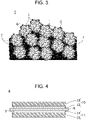
- the electrode catalyst layer 5 of a fuel battery according to Modification 4 may further include at least one carbon material 7 of carbon black or carbon nanotubes in addition to the structure according to the second embodiment.
- the average particle diameter of the carbon material 7 is smaller than the average particle diameter of the mesoporous material 2, and is, for example, greater than or equal to 10 nm and less than or equal to 100 nm.
- the carbon material 7 is disposed between the mesoporous material particles 2 adjacent to one another and fills the gap between them.
- the carbon material 7 which are carbon black and/or carbon nanotubes causes a capillary phenomenon, it prevents the stagnation of water in the gap between the mesoporous material 2 particles. As a result, the drainage properties of the electrode catalyst layer 5 are enhanced, and accordingly, the efficiency of a power generation reaction of a fuel battery can be enhanced. Furthermore, because the carbon material 7 has conductivity, it aids the conductivity between the mesoporous material 2 particles. As a result, the resistance of the electrode catalyst layer 5 is reduced, and accordingly, the efficiency of the power generation reaction of the fuel battery can be enhanced.
- a membrane-electrode assembly 8 includes a polymer electrolyte membrane 9; and a fuel electrode 10 and an air electrode 11.
- the fuel electrode 10 and the air electrode 11 are respectively disposed on both main surfaces of the polymer electrolyte membrane 9, the fuel electrode 10 and the air electrode 11 each including an electrode catalyst layer and a gas diffusion layer.
- At least the electrode catalyst layer of the air electrode 11 includes the electrode catalyst layer 5 of a fuel battery according to the second embodiment or Modification 4 thereof.
- the polymer electrolyte membrane 9 combines proton conductivity and gas barrier properties, and examples thereof include ion exchange fluororesin membranes or ion exchange hydrocarbon resin membranes. Among these, a perfluorosulfonic acid resin membrane has high proton conductivity and is capable of being stably present, for example, even in a power generation environment of a fuel battery, and thus it is preferable as the polymer electrolyte membrane 9.
- the electrode catalyst layer 5 includes a pair of surfaces (main surfaces), and the dimension between them (film thickness) is, for example, greater than or equal to 5 ⁇ m and less than or equal to 50 ⁇ m.
- film thickness is, for example, greater than or equal to 5 ⁇ m and less than or equal to 50 ⁇ m.
- the film thickness is greater than or equal to 5 ⁇ m, the polymer electrolyte membrane 9 is capable of obtaining high gas barrier properties.
- the film thickness is less than or equal to 50 ⁇ m, the polymer electrolyte membrane 9 is capable of obtaining high proton conductivity.
- the fuel electrode 10 is disposed on a first main surface of the pair of the main surfaces of the polymer electrolyte membrane 9 and the air electrode 11 is disposed on a second main surface of the pair of the main surfaces of the polymer electrolyte membrane 9.
- the fuel electrode 10 and the air electrode 11 have the polymer electrolyte membrane 9 interposed therebetween.
- the air electrode 11 is a cathode electrode of the fuel battery and includes an electrode catalyst layer (a second electrode catalyst layer 14) and a gas diffusion layer (a second gas diffusion layer 15).
- a first surface of the second electrode catalyst layer 14 is disposed on the second main surface of the polymer electrolyte membrane 9 and a first surface of the second gas diffusion layer 15 is disposed on a second surface of the second electrode catalyst layer 14.
- a water repellent layer may be disposed between the first gas diffusion layer 13 and the first electrode catalyst layer 12 and between the second gas diffusion layer 15 and the second electrode catalyst layer 14.
- the water repellent layer is a layer for enhancing the liquid permeability (drainage properties).
- the water repellent layer is formed of, for example, a conductive material such as carbon black and a water repellent resin such as polytetrafluoroethylene (PTFE) as a main component.
- PTFE polytetrafluoroethylene
- Each of the electrode catalyst layers 12 and 14 is a layer accelerating the rate of a power generation reaction of the electrodes.
- the first electrode catalyst layer 12 may include the electrode catalyst layer 5 and may have the same structure as a commonly used existing electrode catalyst layer in the membrane-electrode assembly 8 of a fuel battery. Because the second electrode catalyst layer 14 is constituted by the electrode catalyst layer 5, the deterioration of the catalyst activity of the membrane-electrode assembly 8 can be reduced.
- a fuel battery 16 according to a fourth embodiment includes the membrane-electrode assembly 8 according to the third embodiment.
- the fuel battery 16 is constituted by a single cell having one cell, but may be constituted by a stack of a plurality of cells, the cells being layered.
- the membrane-electrode assembly 8 is interposed between a pair of separators 17 and 18.
- a first separator 17 is disposed on the fuel electrode 10 and has a surface facing a second surface of the first gas diffusion layer 13 (a surface of the first gas diffusion layer 13 facing away from the first electrode catalyst layer 12 side).
- This surface includes a supply channel for supplying fuel gas such as hydrogen to the fuel electrode 10.
- a second separator 18 is disposed on the air electrode 11 and has a surface facing a second surface of the second gas diffusion layer 15 (a surface of the gas diffusion layer 15 facing away from the second electrode catalyst layer 14 side).
- This surface includes a supply channel for supplying oxidant gas such as air to the air electrode 11.
- mesoporous carbon having a design pore size of 10 nm (CNovel, manufactured by Toyo Tanso Co., Ltd.) was used as a mesoporous material. This mesoporous carbon was placed into a mixed solvent containing equal amounts of water and ethanol to thereby adjust a slurry having a solid concentration of 1 wt%. Pulverization treatment was thereafter performed on the mesoporous carbon.
- the average particle diameter of the mesoporous carbon was adjusted by dry pulverization treatment.
- the same method as with the electrode catalyst of Example 1 was performed to form the electrode catalyst of Example 2.
- the BET specific surface area Sa was determined by evaluating the mesoporous carbon according to a BET method.
- the pore surface area ratio (S 1-25 /Sa) was obtained by dividing the specific surface area S 1-25 (m 2 /g) of the mesopores 4 by the BET specific surface area Sa (m 2 /g) of the mesoporous carbon.
- the specific surface area S 1-25 and the mode radius of the mesopores of the mesoporous carbon, before the mesoporous carbon supported the catalyst metal, were determined from an adsorption isotherm of nitrogen gas at a liquid nitrogen temperature. Specifically, using a physical adsorption apparatus (Autosorb-iQ2, manufactured by Anton Paar GmbH), the nitrogen adsorption isotherm of the mesoporous carbon was measured, and using an analysis software accompanying the apparatus, the cumulative pore size distribution (S vs D) and the log differential pore size distribution (dS/d(logD) vs D) were calculated according to a BJH method.
- the specific surface area S 1-25 of the mesopores of the mesoporous carbon was calculated from the numerical data of the cumulative pore size distribution. Furthermore, the peak maximum value of the log differential pore size distribution was determined as the mode radius of the mesoporous carbon.
- the electrode catalysts of Examples 1 and 2 and Comparative Examples 1 and 2 were each obtained.
- Each electrode catalyst and Ketjen black (EC300J, manufactured by Lion Specialty Chemicals Co., Ltd) having half the weight of the mesoporous carbon contained in each electrode catalyst were placed into a mixed solvent containing equal amounts of water and ethanol, and stirring was performed.
- an ionomer (Nafion, manufactured by Dupont, Inc.) was placed such that the weight ratio of the ionomer to the total carbon (mesoporous carbon + Ketjen black) would be 0.8, and ultrasonic dispersion treatment was performed.
- the catalyst ink thus obtained was applied to a first main surface of a polymer electrolyte membrane (GORE-SELECT III, manufactured by W. L. Gore and Associates G. K.) according to a spray method to thereby form a second electrode catalyst layer.
- a polymer electrolyte membrane GORE-SELECT III, manufactured by W. L. Gore and Associates G. K.
- a commercially available platinum-supporting carbon black catalyst (TEC10E50E, manufactured by TANAKA Kikinzoku Kogyo K. K.) was placed into a mixed solvent containing equal amounts of water and ethanol, and stirring was performed.
- an ionomer Nafion, manufactured by Dupont, Inc.
- This catalyst ink was applied to a second main surface of the polymer electrolyte membrane (a surface facing away from the second electrode catalyst layer side) according to a spray method to thereby form a first electrode catalyst layer.
- a first gas diffusion layer (GDL25BC, manufactured by SGL Carbon Japan Co., Ltd.) was disposed on the first electrode catalyst layer, and a second gas diffusion layer (GDL25BC, manufactured by SGL Carbon Japan Co., Ltd.) was disposed on the second electrode catalyst layer.
- a pressure of 7 kgf/cm 2 was applied at a high temperature of 140°C for 5 minutes to thereby form a membrane-electrode assembly.
- the membrane-electrode assembly obtained was interposed between separators each including a flow channel having a serpentine shape. This interposed structure was fitted into a predetermined jig to thereby form a fuel battery of a single cell.
- the temperature of the fuel battery obtained was kept at 80°C, and hydrogen having a dew point of 80°C was supplied to a fuel electrode and oxygen having a dew point of 80°C was supplied to an air electrode.
- the hydrogen and the oxygen were each supplied at a flow rate sufficiently larger than the amount to be consumed by an electrochemical reaction (oxidation-reduction reaction) of the fuel battery.
- each voltage of the fuel battery was measured during constant current operation.
- the electrical resistance of the fuel battery was measured in-situ.
- a current value at 0.9 V was read and was thereafter normalized by the platinum amount contained in the electrode catalyst layer of the air electrode to thereby obtain the index of the catalyst activity. This is called a mass activity at 0.9 V (A/g-Pt) and is commonly used as an index indicating the catalyst activity of a fuel battery.
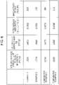
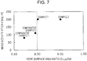
- the table of Fig. 6 and the graph of Fig. 7 illustrate the relationship between the pore surface area ratio (S 1-25 /Sa) of the mesoporous carbon and the mass activity at 0.9 V (A/g-Pt) of the fuel batteries in the cases of the fuel batteries including the electrode catalysts of Examples 1 and 2 and Comparative Examples 1 and 2. As presented, it is revealed that the fuel batteries including the electrode catalysts of Examples 1 and 2 have a higher mass activity at 0.9 V than the fuel batteries including the electrode catalysts of Comparative Examples 1 and 2.
- the decrease in the specific surface area of the catalyst metal particles due to the ionomer is reduced to a greater extent and the catalyst activity of the fuel batteries is higher than in the cases of the mesoporous carbon having a pore surface area ratio of less than or equal to 0.90 before supporting the catalyst metal particles.
- Modification 2 is applicable to Modification 1.
- Modification 3 is applicable to Modifications 1 and 2 and a combination of these.
- the electrode catalyst for a fuel battery, the electrode catalyst layer of a fuel battery, the membrane-electrode assembly, and the fuel battery according to the present disclosure are useful as, for example, an electrode catalyst for a fuel battery, an electrode catalyst layer of a fuel battery, a membrane-electrode assembly, and a fuel battery that are capable of reducing the deterioration of the catalyst activity to a greater extent than in the related art.
Abstract
Description
- The present disclosure relates to an electrode catalyst for a fuel battery, an electrode catalyst layer of a fuel battery, a membrane-electrode assembly, and a fuel battery.
- A solid polymer fuel battery including a proton-conductive solid polymer membrane includes a membrane-electrode assembly for subjecting hydrogencontaining fuel gas and oxygen-containing oxidant gas to an electrochemical reaction (a power generation reaction).
- In general, an electrode catalyst layer constituting the membrane-electrode assembly is formed by applying a catalyst paste to a polymer electrolyte membrane or another such base material and thereafter performing drying. This catalyst paste is formed by dispersing a catalyst and a polymer electrolyte having proton conductivity (hereafter referred to as an "ionomer") in a solvent such as water or an alcohol. In the catalyst, a catalyst metal such as platinum is supported on a conductive material such as carbon black. For example, according to
PTL 1 to 3, catalyst metal particles are supported in a carrier formed of mesoporous carbon. -
- PTL 1:
Japanese Patent No. 6150936 - PTL 2:
Japanese Patent No. 5998275 - PTL 3:
Japanese Patent No. 5998277 - However, in the related art (
PTL 1 to 3), room for improvement still exists in terms of reducing the deterioration of the catalyst activity. - The present disclosure has been made in light of the problem described above and has an object to provide an electrode catalyst for a fuel battery, an electrode catalyst layer of a fuel battery, a membrane-electrode assembly, and a fuel battery that are capable of reducing the deterioration of the catalyst activity to a greater extent than in the related art.
- To resolve the problem described above, one aspect of an electrode catalyst for a fuel battery according to the present disclosure includes a mesoporous material and catalyst metal particles supported at least in the mesoporous material. In the electrode catalyst for a fuel battery, before supporting the catalyst metal particles, the mesoporous material has mesopores having a mode radius of greater than or equal to 1 nm and less than or equal to 25 nm and has a value of greater than 0.90, the value being determined by dividing a specific surface area S1-25 (m2/g) of the mesopores obtained by analyzing a nitrogen adsorption-desorption isotherm according to a BJH method, the mesopores having a radius of greater than or equal to 1 nm and less than or equal to 25 nm, by a BET specific surface area (m2/g) evaluated according to a BET method.
- To resolve the problem described above, one aspect of an electrode catalyst layer of a fuel battery according to the present disclosure includes the electrode catalyst for a fuel battery and an ionomer. The electrode catalyst for a fuel battery includes a mesoporous material and catalyst metal particles supported at least in the mesoporous material. In the electrode catalyst for a fuel battery, before supporting the catalyst metal particles, the mesoporous material has mesopores having a mode radius of greater than or equal to 1 nm and less than or equal to 25 nm and has a value of greater than 0.90, the value being determined by dividing a specific surface area S1-25 (m2/g) of the mesopores obtained by analyzing a nitrogen adsorption-desorption isotherm according to a BJH method, the mesopores having a radius of greater than or equal to 1 nm and less than or equal to 25 nm, by a BET specific surface area (m2/g) evaluated according to a BET method.
- To resolve the problem described above, one aspect of a membrane-electrode assembly according to the present disclosure includes a polymer electrolyte membrane; and a fuel electrode and an air electrode respectively disposed on both main surfaces of the polymer electrolyte membrane, the fuel electrode and the air electrode each including an electrode catalyst layer and a gas diffusion layer. In the membrane-electrode assembly, at least the electrode catalyst layer of the air electrode includes the electrode catalyst layer of a fuel battery including the electrode catalyst for a fuel battery and an ionomer. The electrode catalyst for a fuel battery includes a mesoporous material and catalyst metal particles supported at least in the mesoporous material. In the electrode catalyst for a fuel battery, before supporting the catalyst metal particles, the mesoporous material has mesopores having a mode radius of greater than or equal to 1 nm and less than or equal to 25 nm and has a value of greater than 0.90, the value being determined by dividing a specific surface area S1-25 (m2/g) of the mesopores obtained by analyzing a nitrogen adsorption-desorption isotherm according to a BJH method, the mesopores having a radius of greater than or equal to 1 nm and less than or equal to 25 nm, by a BET specific surface area (m2/g) evaluated according to a BET method.
- To resolve the problem described above, one aspect of a fuel battery according to the present disclosure includes the membrane-electrode assembly including a polymer electrolyte membrane; and a fuel electrode and an air electrode respectively disposed on both main surfaces of the polymer electrolyte membrane, the fuel electrode and the air electrode each including an electrode catalyst layer and a gas diffusion layer. In the membrane-electrode assembly, at least the electrode catalyst layer of the air electrode includes the electrode catalyst layer of a fuel battery including the electrode catalyst for a fuel battery and an ionomer. The electrode catalyst for a fuel battery includes a mesoporous material and catalyst metal particles supported at least in the mesoporous material. In the electrode catalyst for a fuel battery, before supporting the catalyst metal particles, the mesoporous material has mesopores having a mode radius of greater than or equal to 1 nm and less than or equal to 25 nm and has a value of greater than 0.90, the value being determined by dividing a specific surface area S1-25 (m2/g) of the mesopores obtained by analyzing a nitrogen adsorption-desorption isotherm according to a BJH method, the mesopores having a radius of greater than or equal to 1 nm and less than or equal to 25 nm, by a BET specific surface area (m2/g) evaluated according to a BET method.
- The present disclosure has an effect where the electrode catalyst for a fuel battery, the electrode catalyst layer of a fuel battery, the membrane-electrode assembly, and the fuel battery are capable of reducing the deterioration of the catalyst activity to a greater extent than in the related art.
-
- [
Fig. 1] Fig. 1 is a view schematically illustrating an example of an electrode catalyst for a fuel battery according to a first embodiment. - [
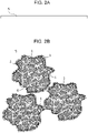
Fig. 2] Fig. 2A is a view schematically illustrating an example of an electrode catalyst layer of a fuel battery according to a second embodiment.Fig. 2B is an enlarged view of a portion ofFig. 2A . - [
Fig. 3] Fig. 3 is a view schematically illustrating a portion of an example of an electrode catalyst layer of a fuel battery according toModification 4 of the second embodiment. - [
Fig. 4] Fig. 4 is a sectional view schematically illustrating an example of a membrane-electrode assembly according to a third embodiment. - [
Fig. 5] Fig. 5 is a sectional view schematically illustrating an example of a fuel battery according to a fourth embodiment. - [
Fig. 6] Fig. 6 is a table illustrating the catalyst activity of fuel batteries respectively including the electrode catalyst of Example 1, Example 2, Comparative Example 1, and Comparative Example 2. - [
Fig. 7] Fig. 7 is a graph illustrating the relationship between the pore surface area ratio of mesoporous carbon and the catalyst activity of the fuel batteries in the cases of the fuel batteries respectively including the electrode catalyst of Example 1, Example 2, Comparative Example 1, and Comparative Example 2. - The present inventors have repeatedly conducted intensive studies on the deterioration of the catalyst activity in the existing techniques disclosed in
PTL 1 to 3. As a result, the inventors have focused on the fact that the ratio of the surface area of mesopores to the whole surface area of a mesoporous carbon carrier contributes to the deterioration of the catalyst activity of catalyst metal particles that is caused by an ionomer. Thus, the inventors have found that the deterioration of the catalyst activity is reduced by, before a mesoporous material supports catalyst metal particles, making the mesoporous material have a value of greater than 0.90, the value being determined by dividing a specific surface area S1-25 (m2/g) of mesopores obtained by analysis according to a BJH method, the mesopores having a radius of greater than or equal to 1 nm and less than or equal to 25 nm, by a BET specific surface area (m2/g) evaluated according to a BET method. The present disclosure has been made based on this knowledge. Accordingly, the present disclosure specifically provides the aspects described below. - An electrode catalyst for a fuel battery according to a first aspect of the present disclosure includes a mesoporous material and catalyst metal particles supported at least in the mesoporous material, where, before supporting the catalyst metal particles, the mesoporous material may have mesopores having a mode radius of greater than or equal to 1 nm and less than or equal to 25 nm and may have a value of greater than 0.90, the value being determined by dividing a specific surface area S1-25 (m2/g) of the mesopores obtained by analyzing a nitrogen adsorption-desorption isotherm according to a BJH method, the mesopores having a radius of greater than or equal to 1 nm and less than or equal to 25 nm, by a BET specific surface area (m2/g) evaluated according to a BET method.
- According to this structure, many catalyst metal particles can be supported in the mesopores of the mesoporous material. Furthermore, for example, even when an ionomer is in contact with the electrode catalyst, because the ionomer is less likely to enter the mesopores, the surface area of the catalyst metal particles covered with the ionomer can be reduced. Thus, the deterioration of the catalyst activity of the electrode catalyst due to the covering of the catalyst metal particles with the ionomer can be reduced.
- In an electrode catalyst for a fuel battery according to a second aspect of the present disclosure, in the first aspect, the mesopores of the mesoporous material may have a mode radius of greater than 1.65 nm.
- According to this structure, aggregation even under severe conditions during the operation of a fuel battery is prevented or reduced to a greater extent in the case of the mesoporous material in which the mesopores have a mode radius of greater than 1.65 nm than in the case of a mesoporous material in which the mesopores have a mode radius of less than or equal to 1.65 nm. Thus, the decrease in the specific surface area of the mesoporous material and that of the catalyst metal particles supported in the mesoporous material due to aggregation is reduced, and accordingly, the deterioration of the catalyst activity of the electrode catalyst can be reduced.
- In an electrode catalyst for a fuel battery according to a third aspect of the present disclosure, in the first or the second aspect, the BET specific surface area of the mesoporous material may be greater than or equal to 1500 (m2/g). Aggregation of the catalyst metal particles supported in the mesoporous material is reduced to a greater extent in the case of the mesoporous material having a BET specific surface area of greater than or equal to 1500 (m2/g) than in the case of a mesoporous material having a BET specific surface area of less than 1500 (m2/g). Thus, the decrease in the specific surface area of the catalyst metal particles due to aggregation is reduced, and accordingly, the deterioration of the catalyst activity of the electrode catalyst can be reduced.
- In an electrode catalyst for a fuel battery according to a fourth aspect of the present disclosure, in any one of the first to the third aspects, among the catalyst metal particles supported in the mesoporous material, the catalyst metal particles supported in the mesopores may be greater than or equal to 0.90. According to this structure, for example, even when an ionomer is in contact with the electrode catalyst, the deterioration of the catalyst activity of the electrode catalyst due to the covering of the catalyst metal particles with the ionomer can be reduced.
- An electrode catalyst layer of a fuel battery according to a fifth aspect of the present disclosure may include at least the electrode catalyst for a fuel battery according to any one of the first to the fourth aspects and at least an ionomer. According to this structure, because the deterioration of the catalyst activity of the electrode catalyst due to the covering of the catalyst metal particles with the ionomer is reduced, the deterioration of the catalyst activity of the electrode catalyst layer due to the ionomer can be prevented or reduced.
- An electrode catalyst layer of a fuel battery according to a sixth aspect of the present disclosure, in the fifth aspect, may include at least one of carbon black or carbon nanotubes. According to this structure, due to the carbon black and/or the carbon nanotubes, the drainage properties of the electrode catalyst layer is enhanced, and the deterioration of the catalyst activity of and the gas diffusivity in the electrode catalyst layer due to water can be reduced. Furthermore, due to the carbon black and/or the carbon nanotubes, the electrical resistance between the mesoporous material particles can be reduced.
- A membrane-electrode assembly according to a seventh aspect of the present disclosure may include a polymer electrolyte membrane; and a fuel electrode and an air electrode respectively disposed on both main surfaces of the polymer electrolyte membrane, the fuel electrode and the air electrode each including an electrode catalyst layer and a gas diffusion layer, where at least the electrode catalyst layer of the air electrode may include the electrode catalyst layer of a fuel battery according to the fifth or the sixth aspect. According to this structure, because the deterioration of the catalyst activity of the electrode catalyst layer is reduced, the deterioration of the catalyst activity of the membrane-electrode assembly can be reduced.
- A fuel battery according to an eighth aspect of the present disclosure may include the membrane-electrode assembly according to the seventh aspect. According to this structure, because the deterioration of the catalyst activity of the membrane-electrode assembly is reduced, the deterioration of the catalyst activity of the fuel battery can be reduced.
- Hereafter, embodiments of the present disclosure will be described with reference to the drawings. Hereafter, throughout all the drawings, the same reference signs are assigned to the same or corresponding constituent members, and the description thereof may be omitted.
- As illustrated in
Fig. 1 , anelectrode catalyst 1 for a fuel battery according to a first embodiment includes amesoporous material 2 andcatalyst metal particles 3 supported at least in themesoporous material 2. - The
mesoporous material 2 is formed of a porous material havingmany mesopores 4 and is a carrier in which thecatalyst metal particles 3 are supported. Themesoporous material 2 has, for example a particle shape, but is not limited thereto. The average particle diameter of themesoporous material 2 is, for example, greater than or equal to 200 nm. The average particle diameter is the median diameter (D50) of the particle size distribution of themesoporous material 2. Furthermore, examples of themesoporous material 2 include mesoporous carbon and oxides of, for example, titanium, tin, niobium, tantalum, zirconium, aluminum, and silicon (silicon). - The
mesopores 4 are pores formed in themesoporous material 2, open at the outer surface of themesoporous material 2, and extend from the opening into themesoporous material 2. Some of a plurality of themesopores 4 or all themesopores 4 may penetrate through themesoporous material 2. Before themesoporous material 2 supports thecatalyst metal particles 3, themesopores 4 have a mode radius of greater than or equal to 1 nm and less than or equal to 25 nm. The mode radius refers to the most frequent diameter in a diameter distribution of themesopores 4 of the mesoporous material 2 (the radius corresponding to a maximum value). The radius of themesopore 4 is half the dimension thereof in the direction perpendicular to the direction in which themesopore 4 extends. - The mode radius of the
mesopores 4 may be greater than or equal to 3 nm and less than or equal to 6 nm, and furthermore, may be greater than or equal to 3 nm and less than or equal to 4 nm. When the mode radius of themesopores 4 is greater than or equal to 3 nm, gas is likely to pass through themesopores 4. When the mode radius is less than or equal to 4 nm, for example, even in the case where an ionomer is in contact with theelectrode catalyst 1, the ionomer is less likely to enter themesopores 4. - The pore volume of the
mesopores 4 may be greater than or equal to 1.0 cm3/g and less than or equal to 3.0 cm3/g. When the pore volume of themesopores 4 is greater than or equal to 1.0 cm3/g, manycatalyst metal particles 3 can be supported in the mesoporous material 2 (i.e., the mesopores 4). When the pore volume is less than or equal to 3.0 cm3/g, themesoporous material 2 is capable of having high strength as a structural body. - The pore volume and the mode radius of the
mesopores 4 are determined by analyzing nitrogen adsorption-desorption isotherm measurement data according to a method such as a BJH method, a Non-Localized Density Functional Theory (NLDFT) method, or a Quenched Solid Density Functional Theory (QSDFT) method. - Before supporting the
catalyst metal particles 3, themesoporous material 2 has a pore surface area ratio of greater than 0.90. The pore surface area ratio (S1-25/Sa) is a value determined by dividing a specific surface area S1-25 (m2/g) of themesopores 4, themesopores 4 having a radius of greater than or equal to 1 nm and less than or equal to 25 nm, by a BET specific surface area Sa (m2/g) evaluated according to a BET method. - The specific surface area S1-25 of the
mesopores 4 is obtained by analyzing a nitrogen adsorption-desorption isotherm of themesoporous material 2 according to a Barrett-Joyner-Halenda (BJH) method. This nitrogen adsorption-desorption isotherm is measured by causing themesoporous material 2 to adsorb nitrogen at a predetermined temperature such as a liquid nitrogen temperature. The specific surface area S1-25 is the inner surface area per unit weight of themesoporous material 2, and the inner surface of themesoporous material 2 is a surface of themesoporous material 2 defining themesopores 4, themesopores 4 having a radius of greater than or equal to 1 nm and less than or equal to 25 nm. - The BET specific surface area Sa is obtained by evaluating the
mesoporous material 2 according to a Brunauer-Emmett-Teller (BET) method and is the whole surface (inner surface and outer surface) area per unit weight of themesoporous material 2. For example, according to the BET method, the surface area of themesoporous material 2 is determined by applying a BET equation to a region of a nitrogen adsorption-desorption isotherm, the region being a region of a relative pressure of greater than or equal to 0.05 and less than or equal to 0.35. The outer surface of themesoporous material 2 is, of the whole surface of themesoporous material 2, a surface other than the inner surface. - The production method for the
mesoporous material 2 is not particularly limited, but, for example, a method disclosed inPTL 3 can be suitably used. Themesoporous material 2 produced according to the method hasmesopores 4 having a large pore volume and a structure in which themesopores 4 are in communication with one another. Thus, themesoporous material 2 easily supports thecatalyst metal particles 3 in themesopores 4, and gas is likely to be supplied to thecatalyst metal particles 3 supported in themesoporous material 2. - The average particle diameter of the
mesoporous material 2 may be adjusted by pulverization treatment. In the pulverization treatment, for example, a pulverization method such as a wet bead mill, a dry bead mill, a wet ball mill, a dry ball mill, a wet jet mill, or a dry jet mill is used. Among these, according to pulverization treatment using a wet bead mill, themesoporous material 2 is likely to be pulverized to a small particle diameter. - The
catalyst metal particles 3 are supported at least in themesoporous material 2. That is, thecatalyst metal particles 3 are supported at the inner surface of themesoporous material 2, in themesopores 4. Thecatalyst metal particles 3 may be supported or unsupported at the outer surface of themesoporous material 2. - The
catalyst metal particles 3 are formed of, for example, platinum (Pt), ruthenium (Ru), palladium (Pd), iridium (Ir), silver (Ag), or gold (Au). The platinum and alloys thereof have a high catalyst activity for an oxidation-reduction reaction and good durability in a power generation environment of a fuel battery, and are thus appropriate as theelectrode catalyst 1 for a fuel battery. - The average particle diameter of the
catalyst metal particles 3 is, for example, greater than or equal to 1 nm and less than or equal to 20 nm, and furthermore, may be greater than or equal to 1 nm and less than or equal to 10 nm. When the average particle diameter of thecatalyst metal particles 3 is less than or equal to 10 nm, the surface area per unit weight (specific surface area) of thecatalyst metal particles 3 is large, and thus the catalyst activity of thecatalyst metal particles 3 is high. When the average particle diameter of thecatalyst metal particles 3 is greater than or equal to 1 nm, thecatalyst metal particles 3 are chemically stabilized, and, for example, are less likely to melt even in a power generation environment of a fuel battery. - The weight ratio of the
catalyst metal particles 3 to the weight of themesoporous material 2 may be greater than or equal to 0.65 and less than or equal to 1.5. When the weight ratio is greater than or equal to 0.65, the amount of a catalyst metal required for a fuel battery can be obtained without increasing the thickness of an electrode catalyst layer including theelectrode catalyst 1. When the weight ratio is less than or equal to 1.5, the amount of thecatalyst metal particles 3 per unit area of themesoporous material 2 is not excessively large, and thus thecatalyst metal particles 3 are less likely to aggregate and are likely to be diffused to the surface of themesoporous material 2. - As in this structure, before supporting the
catalyst metal particles 3, themesoporous material 2 has themesopores 4 having a mode radius of greater than or equal to 1 nm and less than or equal to 25 nm and has a value of greater than 0.90, the value being determined by dividing a specific surface area S1-25 (m2/g) of themesopores 4 obtained by analyzing a nitrogen adsorption-desorption isotherm according to a BJH method, themesopores 4 having a radius of greater than or equal to 1 nm and less than or equal to 25 nm, by a BET specific surface area (m2/g) evaluated according to a BET method. - In the case of the
electrode catalyst 1 in which themesoporous material 2 has a pore surface area ratio (S1-25/Sa) of greater than 0.90, morecatalyst metal particles 3 can be supported at the inner surface of themesoporous material 2, in themesopores 4, than in the case of an electrode catalyst in which themesoporous material 2 has a pore surface area ratio of less than or equal to 0.90. Furthermore, for example, even when an ionomer is in contact with theelectrode catalyst 1, because the ionomer is less likely to enter themesopores 4, the specific surface of thecatalyst metal particles 3 covered with the ionomer can be reduced. Thus, the deterioration of the catalyst activity of theelectrode catalyst 1 due to the covering of thecatalyst metal particles 3 with the ionomer can be reduced. - In an
electrode catalyst 1 for a fuel battery according toModification 1, in the first embodiment, themesopores 4 of themesoporous material 2 may have a mode radius of greater than 1.65 nm. In this case, the mode radius of themesopores 4 may be less than or equal to 25 nm, less than or equal to 6 nm, and less than or equal to 4 nm. - The
mesoporous material 2 in which themesopores 4 have a mode radius of greater than 1.65 nm is less likely to aggregate even under severe conditions during the operation of a fuel battery than a mesoporous material in which themesopores 4 have a mode radius of less than or equal to 1.65 nm. Thus, the decrease in the specific surface area of themesoporous material 2 and that of thecatalyst metal particles 3 supported in themesoporous material 2 due to aggregation is reduced, and accordingly, the deterioration of the catalyst activity of theelectrode catalyst 1 can be reduced. - Even when the
catalyst metal particles 3 having a particle diameter of greater than or equal to 1 nm are supported at the inner surface of themesoporous material 2, in themesopores 4, themesopores 4 are less likely to be blocked by thecatalyst metal particles 3. Thus, for example, even when water is produced during a power generation reaction of a fuel battery, the water is drained through the gap between thecatalyst metal particles 3 and the inner circumferential surface of themesoporous material 2. Thus, the deterioration of the catalyst activity that is caused by the decrease in the specific surface area of thecatalyst metal particles 3 due to water can be reduced. Furthermore, because gas is supplied through themesopores 4 to thecatalyst metal particles 3, the deterioration of the power generation performance of the fuel battery can be prevented or reduced. - In an
electrode catalyst 1 for a fuel battery according toModification 2, in the first embodiment andModification 1, the BET specific surface area of themesoporous material 2 may be greater than or equal to 1500 (m2/g). - Aggregation of the
catalyst metal particles 3 supported in themesoporous material 2 is reduced to a greater extent in the case of themesoporous material 2 having a BET specific surface area of greater than or equal to 1500 (m2/g) than in the case of amesoporous material 2 having a BET specific surface area of less than 1500 (m2/g). Thus, the decrease in the specific surface area of thecatalyst metal particles 3 due to aggregation is reduced, and accordingly, the deterioration of the catalyst activity of theelectrode catalyst 1 can be reduced. - In an
electrode catalyst 1 for a fuel battery according toModification 3, in the first embodiment andModifications catalyst metal particles 3 supported in themesoporous material 2, thecatalyst metal particles 3 supported in themesopores 4 may be greater than or equal to 0.90. - Thus, an Na number of the
catalyst metal particles 3 are supported at the surface of themesoporous material 2, and of this surface, an No number of thecatalyst metal particles 3 are supported at the outer surface and an Ni number of thecatalyst metal particles 3 are supported at the inner surface. The ratio of the number of thecatalyst metal particles 3 supported at the outer surface to the number of thecatalyst metal particles 3 supported at the whole surface (No/Na) is less than 0.10, and the ratio of the number of thecatalyst metal particles 3 supported at the inner surface to the number of thecatalyst metal particles 3 supported at the whole surface (Ni/Na) is greater than or equal to 0.90. Thus, in the case of theelectrode catalyst 1 having an Ni/Na of greater than or equal to 0.90, for example, when an ionomer is in contact with theelectrode catalyst 1, the specific surface area of thecatalyst metal particles 3 covered with the ionomer can be kept smaller than in the case of anelectrode catalyst 1 having an Ni/Na of less than 0.90. Thus, the decrease in the specific surface area of thecatalyst metal particles 3 due to the ionomer is reduced, and accordingly, the deterioration of the catalyst activity of theelectrode catalyst 1 can be reduced. - As illustrated in
Figs. 2A and 2B , anelectrode catalyst layer 5 of a fuel battery according to a second embodiment includes theelectrode catalyst 1 and anionomer 6. Theelectrode catalyst 1 is at least one of the electrode catalysts for a fuel battery according to the first embodiment orModifications 1 to 3 thereof. Theelectrode catalyst layer 5 is, for example, a thin film and may have a flat shape having a small thickness. - The
ionomer 6 is a polymer electrolyte covering the outer surface of theelectrode catalyst 1 and having proton conductivity and is formed of, for example, an ion exchange resin. Among ion exchange resins, a perfluorosulfonic acid resin has high proton conductivity and is stably present even in a power generation environment of a fuel battery, and thus it is suitably used as theionomer 6 of theelectrode catalyst layer 5 of a fuel battery. For example, when theelectrode catalyst layer 5 is used for a fuel battery, the fuel battery is capable of obtaining high power generation performance due to the proton conductivity of theionomer 6. - The ion exchange capacity of an ion exchange resin may be greater than or equal to 0.9 milliequivalent/g of dry resin and less than or equal to 2.0 milliequivalent/g of dry resin. When the ion exchange capacity is greater than or equal to 0.9 milliequivalent/g of dry resin, the
ionomer 6 is likely to obtain high proton conductivity. When the ion exchange capacity is less than or equal to 2.0 milliequivalent/g of dry resin, the swelling of the resin due to water content is prevented or reduced, and the gas diffusivity in theelectrode catalyst layer 5 is less likely to be inhibited. - In the
electrode catalyst 1, before supporting thecatalyst metal particles 3, themesoporous material 2 has a pore surface area ratio of greater than 0.90. Thus, the decrease in the specific surface area of thecatalyst metal particles 3 due to theionomer 6 is reduced, and accordingly, the deterioration of the catalyst activity of theelectrode catalyst layer 5 due to theionomer 6 can be prevented or reduced. - The
electrode catalyst layer 5 is produced according to a production method commonly used for fuel batteries. For example, thecatalyst metal particles 3 are supported in themesoporous material 2 to thereby form theelectrode catalyst 1 for a fuel battery. Thiselectrode catalyst 1 and theionomer 6 are dispersed in a solvent containing water and/or an alcohol. This dispersion is applied to the base materials such as a polymer electrolyte membrane, gas diffusion layers, and various transfer films and thereafter dried to thereby form theelectrode catalyst layer 5. - As illustrated in
Fig. 3 , theelectrode catalyst layer 5 of a fuel battery according toModification 4 may further include at least onecarbon material 7 of carbon black or carbon nanotubes in addition to the structure according to the second embodiment. - Examples of the carbon black include Ketjen black, acetylene black, Vulcan, and Black Pearls. Among these, Ketjen black is capable of forming an effective drainage path in the
electrode catalyst layer 5 even with a small amount added, because an aggregate of Ketjen black is linearly developed. Examples of the carbon nanotubes include single-layer carbon nanotubes and multilayer carbon nanotubes. - The average particle diameter of the
carbon material 7 is smaller than the average particle diameter of themesoporous material 2, and is, for example, greater than or equal to 10 nm and less than or equal to 100 nm. Thecarbon material 7 is disposed between themesoporous material particles 2 adjacent to one another and fills the gap between them. - Thus, because the
carbon material 7 which are carbon black and/or carbon nanotubes causes a capillary phenomenon, it prevents the stagnation of water in the gap between themesoporous material 2 particles. As a result, the drainage properties of theelectrode catalyst layer 5 are enhanced, and accordingly, the efficiency of a power generation reaction of a fuel battery can be enhanced. Furthermore, because thecarbon material 7 has conductivity, it aids the conductivity between themesoporous material 2 particles. As a result, the resistance of theelectrode catalyst layer 5 is reduced, and accordingly, the efficiency of the power generation reaction of the fuel battery can be enhanced. - As illustrated in
Fig. 4 , a membrane-electrode assembly 8 according to a third embodiment includes apolymer electrolyte membrane 9; and afuel electrode 10 and anair electrode 11. Thefuel electrode 10 and theair electrode 11 are respectively disposed on both main surfaces of thepolymer electrolyte membrane 9, thefuel electrode 10 and theair electrode 11 each including an electrode catalyst layer and a gas diffusion layer. At least the electrode catalyst layer of theair electrode 11 includes theelectrode catalyst layer 5 of a fuel battery according to the second embodiment orModification 4 thereof. - The
polymer electrolyte membrane 9 combines proton conductivity and gas barrier properties, and examples thereof include ion exchange fluororesin membranes or ion exchange hydrocarbon resin membranes. Among these, a perfluorosulfonic acid resin membrane has high proton conductivity and is capable of being stably present, for example, even in a power generation environment of a fuel battery, and thus it is preferable as thepolymer electrolyte membrane 9. - The
polymer electrolyte membrane 9 is interposed between thefuel electrode 10 and theair electrode 11, and enables the ionic (proton) conduction between them. The ion exchange capacity of thepolymer electrolyte membrane 9 is greater than or equal to 0.9 milliequivalent/g of dry resin and less than or equal to 2.0 milliequivalent/g of dry resin. When the ion exchange capacity is greater than or equal to 0.9 milliequivalent/g of dry resin, thepolymer electrolyte membrane 9 is likely to obtain high proton conductivity. When the ion exchange capacity is less than or equal to 2.0 milliequivalent/g of dry resin, in thepolymer electrolyte membrane 9, the swelling of the resin due to water content is prevented or reduced, and accordingly, the dimensional change of thepolymer electrolyte membrane 9 is prevented or reduced. - The
electrode catalyst layer 5 includes a pair of surfaces (main surfaces), and the dimension between them (film thickness) is, for example, greater than or equal to 5 µm and less than or equal to 50 µm. When the film thickness is greater than or equal to 5 µm, thepolymer electrolyte membrane 9 is capable of obtaining high gas barrier properties. When the film thickness is less than or equal to 50 µm, thepolymer electrolyte membrane 9 is capable of obtaining high proton conductivity. - The
fuel electrode 10 is disposed on a first main surface of the pair of the main surfaces of thepolymer electrolyte membrane 9 and theair electrode 11 is disposed on a second main surface of the pair of the main surfaces of thepolymer electrolyte membrane 9. Thefuel electrode 10 and theair electrode 11 have thepolymer electrolyte membrane 9 interposed therebetween. - The
fuel electrode 10 is an anode electrode of a fuel battery and includes an electrode catalyst layer (a first electrode catalyst layer 12) and a gas diffusion layer (a first gas diffusion layer 13). A first surface of the firstelectrode catalyst layer 12 is disposed on the first main surface of thepolymer electrolyte membrane 9 and a first surface of the firstgas diffusion layer 13 is disposed on a second surface of the firstelectrode catalyst layer 12. - The
air electrode 11 is a cathode electrode of the fuel battery and includes an electrode catalyst layer (a second electrode catalyst layer 14) and a gas diffusion layer (a second gas diffusion layer 15). A first surface of the secondelectrode catalyst layer 14 is disposed on the second main surface of thepolymer electrolyte membrane 9 and a first surface of the secondgas diffusion layer 15 is disposed on a second surface of the secondelectrode catalyst layer 14. - Each of the gas diffusion layers 13 and 15 is a layer combining a current collecting action and gas permeability. Each of the gas diffusion layers 13 and 15 is, for example, a material excelling in conductivity and gas and liquid permeability, and examples thereof include porous materials such as carbon paper, carbon fiber cloth, and carbon fiber felt.
- A water repellent layer may be disposed between the first
gas diffusion layer 13 and the firstelectrode catalyst layer 12 and between the secondgas diffusion layer 15 and the secondelectrode catalyst layer 14. The water repellent layer is a layer for enhancing the liquid permeability (drainage properties). The water repellent layer is formed of, for example, a conductive material such as carbon black and a water repellent resin such as polytetrafluoroethylene (PTFE) as a main component. - Each of the electrode catalyst layers 12 and 14 is a layer accelerating the rate of a power generation reaction of the electrodes. The first
electrode catalyst layer 12 may include theelectrode catalyst layer 5 and may have the same structure as a commonly used existing electrode catalyst layer in the membrane-electrode assembly 8 of a fuel battery. Because the secondelectrode catalyst layer 14 is constituted by theelectrode catalyst layer 5, the deterioration of the catalyst activity of the membrane-electrode assembly 8 can be reduced. - As illustrated in
Fig. 5 , afuel battery 16 according to a fourth embodiment includes the membrane-electrode assembly 8 according to the third embodiment. InFig. 5 , thefuel battery 16 is constituted by a single cell having one cell, but may be constituted by a stack of a plurality of cells, the cells being layered. - The membrane-
electrode assembly 8 is interposed between a pair ofseparators separators first separator 17 is disposed on thefuel electrode 10 and has a surface facing a second surface of the first gas diffusion layer 13 (a surface of the firstgas diffusion layer 13 facing away from the firstelectrode catalyst layer 12 side). This surface includes a supply channel for supplying fuel gas such as hydrogen to thefuel electrode 10. Asecond separator 18 is disposed on theair electrode 11 and has a surface facing a second surface of the second gas diffusion layer 15 (a surface of thegas diffusion layer 15 facing away from the secondelectrode catalyst layer 14 side). This surface includes a supply channel for supplying oxidant gas such as air to theair electrode 11. - Thus, fuel gas and oxidant gas supplied to the
fuel battery 16 are subjected to a power generation reaction in the membrane-electrode assembly 8. In the membrane-electrode assembly 8, the firstelectrode catalyst layer 12 thereof includes theelectrode catalyst layer 5, and thus the deterioration of the catalyst activity is reduced. Accordingly, the deterioration of the catalyst activity of thefuel battery 16 is reduced, and thus thefuel battery 16 is capable of preventing or reducing the deterioration of the power generation efficiency. - Commercially available mesoporous carbon having a design pore size of 10 nm (CNovel, manufactured by Toyo Tanso Co., Ltd.) was used as a mesoporous material. This mesoporous carbon was placed into a mixed solvent containing equal amounts of water and ethanol to thereby adjust a slurry having a solid concentration of 1 wt%. Pulverization treatment was thereafter performed on the mesoporous carbon. Here, zirconia beads having a diameter of 0.5 mm were placed into the slurry, and the pulverization treatment was performed using a medium stirring wet bead mill (LABSTAR Mini, manufactured by Ashizawa Finetech Ltd.) under the condition of a circumferential speed of 12 m/s for 20 minutes. The zirconia beads were recovered from the slurry subjected to the pulverization treatment and the solvent was vaporized, and thereafter the aggregate obtained was ground using a mortar to thereby form a carbon carrier.
- A total of 1 g of the carbon carrier obtained was placed into 400 mL of a mixed solvent of water and ethanol in a ratio (weight ratio) of 3:1, and thereafter ultrasonic dispersion was performed for 15 minutes. After dispersion, under stirring in a nitrogen atmosphere, a 14 wt% dinitrodiamine platinum nitric acid solution was added dropwise thereto such that platinum would be 50 wt% with respect to the carbon carrier, and heat stirring was performed at 80°C for 6 hours. After cooling, filtration washing was performed, and thereafter drying was performed at 80°C for 15 hours. The aggregate obtained was ground using a mortar, and heat treatment was performed in an atmosphere of nitrogen:hydrogen = 85:15 at 220°C for 2 hours to thereby form an electrode catalyst of Example 1.
- In the case of an electrode catalyst of Example 2, the average particle diameter of the mesoporous carbon was adjusted by dry pulverization treatment. Other than this, the same method as with the electrode catalyst of Example 1 was performed to form the electrode catalyst of Example 2.
- Furthermore, other than the conditions for the pulverization treatment performed on the mesoporous carbon, the same method as with the electrode catalyst of Example 1 was performed to form electrode catalysts of Comparative Examples 1 and 2. That is, in Example 1, the pulverization treatment was performed using zirconia beads having a diameter of 0.5 mm under the condition of a circumferential speed of 12 m/s for 20 minutes. On the other hand, in the case of the electrode catalyst of Comparative Example 1, the pulverization treatment was performed using zirconia beads having a diameter of 0.3 mm under the condition of a circumferential speed of 12 m/s for 60 minutes. In the case of the electrode catalyst of Comparative Example 2, the pulverization treatment was performed using zirconia beads having a diameter of 0.5 mm under the condition of a circumferential speed of 12 m/s for 60 minutes.
- As illustrated in
Fig. 6 , with respect to the electrode catalysts of Examples 1 and 2 and Comparative Examples 1 and 2, the specific surface area S1-25 (m2/g) of mesopores of the mesoporous carbon and the BET specific surface area Sa (m2/g) and the pore surface area ratio (S1-25/Sa) of the mesoporous carbon, before the mesoporous carbon supported a catalyst metal, were obtained. The BET specific surface area Sa was determined by evaluating the mesoporous carbon according to a BET method. The pore surface area ratio (S1-25/Sa) was obtained by dividing the specific surface area S1-25 (m2/g) of themesopores 4 by the BET specific surface area Sa (m2/g) of the mesoporous carbon. - The specific surface area S1-25 and the mode radius of the mesopores of the mesoporous carbon, before the mesoporous carbon supported the catalyst metal, were determined from an adsorption isotherm of nitrogen gas at a liquid nitrogen temperature. Specifically, using a physical adsorption apparatus (Autosorb-iQ2, manufactured by Anton Paar GmbH), the nitrogen adsorption isotherm of the mesoporous carbon was measured, and using an analysis software accompanying the apparatus, the cumulative pore size distribution (S vs D) and the log differential pore size distribution (dS/d(logD) vs D) were calculated according to a BJH method. The specific surface area S1-25 of the mesopores of the mesoporous carbon was calculated from the numerical data of the cumulative pore size distribution. Furthermore, the peak maximum value of the log differential pore size distribution was determined as the mode radius of the mesoporous carbon.
- As described above, the electrode catalysts of Examples 1 and 2 and Comparative Examples 1 and 2 were each obtained. Each electrode catalyst and Ketjen black (EC300J, manufactured by Lion Specialty Chemicals Co., Ltd) having half the weight of the mesoporous carbon contained in each electrode catalyst were placed into a mixed solvent containing equal amounts of water and ethanol, and stirring was performed. Into the slurry obtained, an ionomer (Nafion, manufactured by Dupont, Inc.) was placed such that the weight ratio of the ionomer to the total carbon (mesoporous carbon + Ketjen black) would be 0.8, and ultrasonic dispersion treatment was performed. The catalyst ink thus obtained was applied to a first main surface of a polymer electrolyte membrane (GORE-SELECT III, manufactured by W. L. Gore and Associates G. K.) according to a spray method to thereby form a second electrode catalyst layer.
- Furthermore, a commercially available platinum-supporting carbon black catalyst (TEC10E50E, manufactured by TANAKA Kikinzoku Kogyo K. K.) was placed into a mixed solvent containing equal amounts of water and ethanol, and stirring was performed. Into the slurry obtained, an ionomer (Nafion, manufactured by Dupont, Inc.) was placed such that the weight ratio of the ionomer to the carbon would be 0.8, and ultrasonic dispersion treatment was performed to thereby obtain a catalyst ink. This catalyst ink was applied to a second main surface of the polymer electrolyte membrane (a surface facing away from the second electrode catalyst layer side) according to a spray method to thereby form a first electrode catalyst layer.
- Subsequently, a first gas diffusion layer (GDL25BC, manufactured by SGL Carbon Japan Co., Ltd.) was disposed on the first electrode catalyst layer, and a second gas diffusion layer (GDL25BC, manufactured by SGL Carbon Japan Co., Ltd.) was disposed on the second electrode catalyst layer. To the structure obtained, a pressure of 7 kgf/cm2 was applied at a high temperature of 140°C for 5 minutes to thereby form a membrane-electrode assembly.
- The membrane-electrode assembly obtained was interposed between separators each including a flow channel having a serpentine shape. This interposed structure was fitted into a predetermined jig to thereby form a fuel battery of a single cell.
- The temperature of the fuel battery obtained was kept at 80°C, and hydrogen having a dew point of 80°C was supplied to a fuel electrode and oxygen having a dew point of 80°C was supplied to an air electrode. Here, the hydrogen and the oxygen were each supplied at a flow rate sufficiently larger than the amount to be consumed by an electrochemical reaction (oxidation-reduction reaction) of the fuel battery.
- Here, using an electronic load apparatus (PLZ-664WA, manufactured by Kikusui Electronics Corporation) each voltage of the fuel battery was measured during constant current operation. During this measurement, using a lowresistance meter having a fixed frequency of 1 kHz, the electrical resistance of the fuel battery was measured in-situ. From the current-voltage curve corrected using an electrical resistance component of the fuel battery, a current value at 0.9 V was read and was thereafter normalized by the platinum amount contained in the electrode catalyst layer of the air electrode to thereby obtain the index of the catalyst activity. This is called a mass activity at 0.9 V (A/g-Pt) and is commonly used as an index indicating the catalyst activity of a fuel battery.
- The table of
Fig. 6 and the graph ofFig. 7 illustrate the relationship between the pore surface area ratio (S1-25/Sa) of the mesoporous carbon and the mass activity at 0.9 V (A/g-Pt) of the fuel batteries in the cases of the fuel batteries including the electrode catalysts of Examples 1 and 2 and Comparative Examples 1 and 2. As presented, it is revealed that the fuel batteries including the electrode catalysts of Examples 1 and 2 have a higher mass activity at 0.9 V than the fuel batteries including the electrode catalysts of Comparative Examples 1 and 2. That is, in the cases of the mesoporous carbon having a pore surface area ratio of greater than 0.90 before supporting the catalyst metal particles, the decrease in the specific surface area of the catalyst metal particles due to the ionomer is reduced to a greater extent and the catalyst activity of the fuel batteries is higher than in the cases of the mesoporous carbon having a pore surface area ratio of less than or equal to 0.90 before supporting the catalyst metal particles. - Thus, all the embodiments described above may be combined with one another as long as they do not exclude one another. For example,
Modification 2 is applicable toModification 1. Furthermore,Modification 3 is applicable toModifications - From the description above, many improvements and other embodiments of the present disclosure are apparent to those skilled in the art. Thus, it is to be interpreted that the above description is provided merely as an example to explain the best mode of practicing the present disclosure to those skilled in the art. Without departing from the spirit of the present disclosure, the details of the structure and/or the function thereof can be substantially changed.
- The electrode catalyst for a fuel battery, the electrode catalyst layer of a fuel battery, the membrane-electrode assembly, and the fuel battery according to the present disclosure are useful as, for example, an electrode catalyst for a fuel battery, an electrode catalyst layer of a fuel battery, a membrane-electrode assembly, and a fuel battery that are capable of reducing the deterioration of the catalyst activity to a greater extent than in the related art.
-
- 1
- electrode catalyst
- 2
- mesoporous material
- 3
- catalyst metal particle
- 4
- mesopore
- 5
- electrode catalyst layer
- 6
- ionomer
- 7
- carbon material (carbon black, carbon nanotubes)
- 8
- electrode assembly
- 9
- polymer electrolyte membrane
- 10
- fuel electrode
- 11
- air electrode
- 12
- first electrode catalyst layer (electrode catalyst layer)
- 13
- first gas diffusion layer (gas diffusion layer)
- 14
- second electrode catalyst layer (electrode catalyst layer)
- 15
- second gas diffusion layer (gas diffusion layer)
- 16
- fuel battery
- 17
- separator
- 18
- separator
Claims (8)
- An electrode catalyst for a fuel battery, comprising:a mesoporous material; andcatalyst metal particles supported at least in the mesoporous material,wherein, before supporting the catalyst metal particles,the mesoporous material has mesopores having a mode radius of greater than or equal to 1 nm and less than or equal to 25 nm and has a value of greater than 0.90, the value being determined by dividing a specific surface area S1-25 (m2/g) of the mesopores obtained by analyzing a nitrogen adsorption-desorption isotherm according to a BJH method, the mesopores having a radius of greater than or equal to 1 nm and less than or equal to 25 nm, by a BET specific surface area (m2/g) evaluated according to a BET method.
- The electrode catalyst for a fuel battery according to Claim 1, wherein the mesopores of the mesoporous material have a mode radius of greater than 1.65 nm.
- The electrode catalyst for a fuel battery according to Claim 1 or 2, wherein the BET specific surface area of the mesoporous material is greater than or equal to 1500 (m2/g).
- The electrode catalyst for a fuel battery according to any one of Claims 1 to 3, wherein, among the catalyst metal particles supported in the mesoporous material, the catalyst metal particles supported in the mesopores are greater than or equal to 0.90.
- An electrode catalyst layer of a fuel battery comprising at least the electrode catalyst for a fuel battery according to any one of Claims 1 to 4 and at least an ionomer.
- The electrode catalyst layer of a fuel battery according to Claim 5, comprising at least one of carbon black or carbon nanotubes.
- A membrane-electrode assembly comprising:a polymer electrolyte membrane; anda fuel electrode and an air electrode respectively disposed on both main surfaces of the polymer electrolyte membrane, the fuel electrode and the air electrode each including an electrode catalyst layer and a gas diffusion layer,wherein at least the electrode catalyst layer of the air electrode includes the electrode catalyst layer of a fuel battery according to Claim 5 or 6.
- A fuel battery comprising the membrane-electrode assembly according to Claim 7.
Applications Claiming Priority (3)
| Application Number | Priority Date | Filing Date | Title |
|---|---|---|---|
| JP2019224819 | 2019-12-12 | ||
| JP2020169841 | 2020-10-07 | ||
| PCT/JP2020/040475 WO2021117369A1 (en) | 2019-12-12 | 2020-10-28 | Electrode catalyst for fuel cell, electrode catalyst layer for fuel cell, membrane/electrode assembly, and fuel cell |
Publications (2)
| Publication Number | Publication Date |
|---|---|
| EP4074418A1 true EP4074418A1 (en) | 2022-10-19 |
| EP4074418A4 EP4074418A4 (en) | 2023-08-09 |
Family
ID=76329745
Family Applications (1)
| Application Number | Title | Priority Date | Filing Date |
|---|---|---|---|
| EP20886178.1A Pending EP4074418A4 (en) | 2019-12-12 | 2020-10-28 | Electrode catalyst for fuel cell, electrode catalyst layer for fuel cell, membrane/electrode assembly, and fuel cell |
Country Status (5)
| Country | Link |
|---|---|
| US (1) | US20220021005A1 (en) |
| EP (1) | EP4074418A4 (en) |
| JP (1) | JP6931808B1 (en) |
| CN (1) | CN113207317A (en) |
| WO (1) | WO2021117369A1 (en) |
Family Cites Families (11)
| Publication number | Priority date | Publication date | Assignee | Title |
|---|---|---|---|---|
| JPS6094937A (en) | 1983-10-28 | 1985-05-28 | Agency Of Ind Science & Technol | Dihydroxydicarboxylic acid having cyclohexane ring and its ester |
| JPWO2014167981A1 (en) * | 2013-04-11 | 2017-02-16 | ソニー株式会社 | Electrode, manufacturing method thereof, and secondary battery |
| EP2991142B1 (en) * | 2013-04-25 | 2017-05-03 | Nissan Motor Co., Ltd. | Catalyst, electrode catalyst layer using said catalyst, membrane electrode assembly, and fuel cell |
| WO2014175106A1 (en) | 2013-04-25 | 2014-10-30 | 日産自動車株式会社 | Electrode and fuel cell electrode catalyst layer containing same |
| WO2014175098A1 (en) * | 2013-04-25 | 2014-10-30 | 日産自動車株式会社 | Catalyst, electrode catalyst layer using said catalyst, membrane electrode assembly, and fuel cell |
| JP6309386B2 (en) * | 2014-07-31 | 2018-04-11 | 旭化成株式会社 | Carbon catalyst and method for producing the same |
| JP7094075B2 (en) * | 2016-05-18 | 2022-07-01 | 日本製鉄株式会社 | Carbon material for catalyst carrier, catalyst for polymer electrolyte fuel cell, catalyst layer for polymer electrolyte fuel cell, and polymer electrolyte fuel cell |
| JP6566331B2 (en) * | 2017-04-17 | 2019-08-28 | パナソニックIpマネジメント株式会社 | Electrocatalyst layer for electrochemical device, membrane / electrode assembly for electrochemical device, electrochemical device, and method for producing electrode catalyst layer for electrochemical device |
| EP3476475B1 (en) * | 2017-10-27 | 2022-04-06 | Heraeus Battery Technology GmbH | Production of a porous carbon product |
| KR102455117B1 (en) * | 2017-11-16 | 2022-10-14 | 닛신보 홀딩스 가부시키 가이샤 | Cathode, Membrane Electrode Assembly and Battery |
| JP6572416B1 (en) * | 2018-03-26 | 2019-09-11 | 大豊精機株式会社 | Conductive nanofiber member, fuel cell member, fuel cell, and method of manufacturing conductive nanofiber member |
-
2020
- 2020-10-28 CN CN202080005423.6A patent/CN113207317A/en active Pending
- 2020-10-28 WO PCT/JP2020/040475 patent/WO2021117369A1/en unknown
- 2020-10-28 JP JP2021502907A patent/JP6931808B1/en active Active
- 2020-10-28 EP EP20886178.1A patent/EP4074418A4/en active Pending
-
2021
- 2021-05-19 US US17/324,577 patent/US20220021005A1/en active Pending
Also Published As
| Publication number | Publication date |
|---|---|
| US20220021005A1 (en) | 2022-01-20 |
| JP6931808B1 (en) | 2021-09-08 |
| CN113207317A (en) | 2021-08-03 |
| WO2021117369A1 (en) | 2021-06-17 |
| EP4074418A4 (en) | 2023-08-09 |
| JPWO2021117369A1 (en) | 2021-06-17 |
Similar Documents
| Publication | Publication Date | Title |
|---|---|---|
| US10790526B2 (en) | Electrode catalyst layer of electrochemical device, membrane electrode assembly of electrochemical device, and electrochemical device | |
| US11367879B2 (en) | Electrode catalyst of electrochemical device, electrode catalyst layer of electrochemical device, membrane electrode assembly of electrochemical device, electrochemical device, method for manufacturing electrode catalyst of electrochemical device, and method for manufacturing membrane electrode assembly of electrochemical device | |
| EP3520161B1 (en) | Cathode electrode design for electrochemical fuel cells | |
| WO2014175098A1 (en) | Catalyst, electrode catalyst layer using said catalyst, membrane electrode assembly, and fuel cell | |
| EP2991142A1 (en) | Catalyst, electrode catalyst layer using said catalyst, membrane electrode assembly, and fuel cell | |
| JP2008186798A (en) | Electrolyte membrane-electrode assembly | |
| JP4133654B2 (en) | Polymer electrolyte fuel cell | |
| JP6222530B2 (en) | Catalyst layer for fuel cell and fuel cell | |
| WO2010070994A1 (en) | Anode catalyst layer for solid polymer fuel cell | |
| US20190074522A1 (en) | Catalyst electrode layer, membrane-electrode assembly, and fuel cell | |
| EP3553862B1 (en) | Membrane catalyst layer assembly of electrochemical device, membrane electrode assembly, electrochemical device, method for manufacturing membrane catalyst layer assembly of electrochemical device | |
| JP5596277B2 (en) | Membrane electrode assembly and fuel cell | |
| JP2005174835A (en) | Electrode | |
| EP4074418A1 (en) | Electrode catalyst for fuel cell, electrode catalyst layer for fuel cell, membrane/electrode assembly, and fuel cell | |
| JP4271127B2 (en) | Electrode structure of polymer electrolyte fuel cell | |
| JP2006079840A (en) | Electrode catalyst for fuel cell, and mea for fuel cell using this | |
| WO2021131386A1 (en) | Electrode catalyst and electrode catalyst layer of electrochemical device, film/electrode assembly, and electrochemical device | |
| JP5458774B2 (en) | Electrolyte membrane-electrode assembly | |
| JP2007250214A (en) | Electrode catalyst and its manufacturing method | |
| JP2023011964A (en) | Electrode catalyst and electrode catalyst layer for electrochemical device, membrane/electrode assembly, and electrochemical device | |
| JP2021108262A (en) | Manufacturing method electrode for fuel cell | |
| JP2010146762A (en) | Catalyst layer of solid polymer fuel cell |
Legal Events
| Date | Code | Title | Description |
|---|---|---|---|
| STAA | Information on the status of an ep patent application or granted ep patent |
Free format text: STATUS: UNKNOWN |
|
| STAA | Information on the status of an ep patent application or granted ep patent |
Free format text: STATUS: THE INTERNATIONAL PUBLICATION HAS BEEN MADE |
|
| PUAI | Public reference made under article 153(3) epc to a published international application that has entered the european phase |
Free format text: ORIGINAL CODE: 0009012 |
|
| STAA | Information on the status of an ep patent application or granted ep patent |
Free format text: STATUS: REQUEST FOR EXAMINATION WAS MADE |
|
| 17P | Request for examination filed |
Effective date: 20220531 |
|
| AK | Designated contracting states |
Kind code of ref document: A1 Designated state(s): AL AT BE BG CH CY CZ DE DK EE ES FI FR GB GR HR HU IE IS IT LI LT LU LV MC MK MT NL NO PL PT RO RS SE SI SK SM TR |
|
| RIN1 | Information on inventor provided before grant (corrected) |
Inventor name: WADA, TOMOKATSU Inventor name: SHINTANI, HARUHIKO Inventor name: MIYATA, NOBUHIRO |
|
| DAV | Request for validation of the european patent (deleted) | ||
| DAX | Request for extension of the european patent (deleted) | ||
| A4 | Supplementary search report drawn up and despatched |
Effective date: 20230706 |
|
| RIC1 | Information provided on ipc code assigned before grant |
Ipc: H01M 8/1004 20160101ALI20230630BHEP Ipc: B01J 23/42 20060101ALI20230630BHEP Ipc: H01M 8/10 20160101ALI20230630BHEP Ipc: H01M 4/90 20060101ALI20230630BHEP Ipc: H01M 4/86 20060101ALI20230630BHEP Ipc: B01J 35/10 20060101AFI20230630BHEP Ipc: H01M 4/92 20060101ALI20230630BHEP |