EP4074366B1 - Vorrichtungen zur verwaltung von durch wechselfelder induzierten temperaturen - Google Patents
Vorrichtungen zur verwaltung von durch wechselfelder induzierten temperaturen Download PDFInfo
- Publication number
- EP4074366B1 EP4074366B1 EP22177338.5A EP22177338A EP4074366B1 EP 4074366 B1 EP4074366 B1 EP 4074366B1 EP 22177338 A EP22177338 A EP 22177338A EP 4074366 B1 EP4074366 B1 EP 4074366B1
- Authority
- EP
- European Patent Office
- Prior art keywords
- electrodes
- patient
- tumor
- transducer arrays
- electric field
- Prior art date
- Legal status (The legal status is an assumption and is not a legal conclusion. Google has not performed a legal analysis and makes no representation as to the accuracy of the status listed.)
- Active
Links
Images


Classifications
-
- A—HUMAN NECESSITIES
- A61—MEDICAL OR VETERINARY SCIENCE; HYGIENE
- A61N—ELECTROTHERAPY; MAGNETOTHERAPY; RADIATION THERAPY; ULTRASOUND THERAPY
- A61N1/00—Electrotherapy; Circuits therefor
- A61N1/18—Applying electric currents by contact electrodes
- A61N1/32—Applying electric currents by contact electrodes alternating or intermittent currents
- A61N1/36—Applying electric currents by contact electrodes alternating or intermittent currents for stimulation
- A61N1/36002—Cancer treatment, e.g. tumour
-
- A—HUMAN NECESSITIES
- A61—MEDICAL OR VETERINARY SCIENCE; HYGIENE
- A61N—ELECTROTHERAPY; MAGNETOTHERAPY; RADIATION THERAPY; ULTRASOUND THERAPY
- A61N1/00—Electrotherapy; Circuits therefor
- A61N1/02—Details
- A61N1/04—Electrodes
- A61N1/0404—Electrodes for external use
- A61N1/0472—Structure-related aspects
- A61N1/0476—Array electrodes (including any electrode arrangement with more than one electrode for at least one of the polarities)
-
- A—HUMAN NECESSITIES
- A61—MEDICAL OR VETERINARY SCIENCE; HYGIENE
- A61N—ELECTROTHERAPY; MAGNETOTHERAPY; RADIATION THERAPY; ULTRASOUND THERAPY
- A61N1/00—Electrotherapy; Circuits therefor
- A61N1/18—Applying electric currents by contact electrodes
- A61N1/32—Applying electric currents by contact electrodes alternating or intermittent currents
- A61N1/36—Applying electric currents by contact electrodes alternating or intermittent currents for stimulation
- A61N1/36014—External stimulators, e.g. with patch electrodes
- A61N1/3603—Control systems
-
- A—HUMAN NECESSITIES
- A61—MEDICAL OR VETERINARY SCIENCE; HYGIENE
- A61N—ELECTROTHERAPY; MAGNETOTHERAPY; RADIATION THERAPY; ULTRASOUND THERAPY
- A61N1/00—Electrotherapy; Circuits therefor
- A61N1/40—Applying electric fields by inductive or capacitive coupling ; Applying radio-frequency signals
-
- A—HUMAN NECESSITIES
- A61—MEDICAL OR VETERINARY SCIENCE; HYGIENE
- A61N—ELECTROTHERAPY; MAGNETOTHERAPY; RADIATION THERAPY; ULTRASOUND THERAPY
- A61N1/00—Electrotherapy; Circuits therefor
- A61N1/40—Applying electric fields by inductive or capacitive coupling ; Applying radio-frequency signals
- A61N1/403—Applying electric fields by inductive or capacitive coupling ; Applying radio-frequency signals for thermotherapy, e.g. hyperthermia
Definitions
- Tumor Treating Fields are low intensity (e.g., 1-3 V/cm) alternating electric fields within the intermediate frequency range (100-300 kHz). This non-invasive treatment targets solid tumors and is described in U.S. Pat. No. 7,565,205 .
- TTFields disrupt cell division through physical interactions with key molecules during mitosis.
- TTFields therapy is an approved mono-treatment for recurrent glioblastoma and approved combination therapy with chemotherapy for newly diagnosed patients.
- These electric fields are induced non-invasively by transducer arrays (e.g., arrays of electrodes) placed directly on the patient's scalp. TTFields also appear to be beneficial for treating tumors in other parts of the body.
- Disparities in tissue types and geometries may reduce the efficacy of alternating electric fields when applied to a target region.
- the alternating electric fields applied by transducer arrays may produce heat.
- the heat generated by electrodes of a transducer array may cause patient discomfort at a tissue-transducer interface, such as on the surface of the skin.
- US-A-2018/0001075 discloses arrays for longitudinal delivery of TTFields to a body, in which first and second sets of electrodes are affixed at respective positions longitudinally prior and subsequent to a target region, and an AC voltage is applied between these sets of electrodes.
- US-A-10265530 discloses implantable stimulators for applying one or more electrical impulses to targeted excitable tissue, such as nerves.
- US-A-5873849 discloses electrode arrays having at least three individually-addressable electrodes disposed so as to form a triangle in a plane intersecting the electrodes.
- WO-A-2014/025394 discloses a percutaneous catheter system for use within the human body and an ablation catheter for ablating a selected tissue region within the body of a subject.
- the ablation catheter can include electrodes positioned within a central portion, and each electrode of the ablation catheter can be activated independently to apply ablative energy to the selected tissue region.
- US-A-2019/0223946 discloses systems and methods for neuromodulation therapy, and can include intravascularly positioning a plurality of ablation electrodes within a blood vessel lumen at a treatment site.
- the method can include analyzing a renal neuromodulation target site of a patient to obtain patient-specific data related to the renal neuromodulation target site, and, based on the patient specific data, delivering neuromodulation treatment to the patient via one or more of the ablation electrodes.
- the present invention provides the apparatus of claim 1.
- TTFields also referred to herein as alternating electric fields, are established as an anti-mitotic cancer treatment modality because they interfere with proper microtubule assembly during metaphase and eventually destroy the cells during telophase and cytokinesis.
- the efficacy increases with increasing field strength and the optimal frequency are cancer cell line dependent with 200 kHz being the frequency for which inhibition of glioma cell growth caused by TTFields is highest.
- non-invasive devices were developed with capacitively coupled transducers that are placed directly at the skin region close to the tumor, for example, for patients with Glioblastoma Multiforme (GBM), the most common primary, malignant brain tumor in humans.
- GBM Glioblastoma Multiforme
- TTFields are typically delivered through two pairs of transducer arrays that generate perpendicular fields within the treated tumor. More specifically, one pair of transducer arrays may be located to the left and right (LR) of the tumor, and the other pair of transducer arrays may be located anterior and posterior (AP) to the tumor. Cycling the field between these two directions (e.g., LR and AP) ensures that a maximal range of cell orientations is targeted. Other positions of transducer arrays are contemplated beyond perpendicular fields.
- asymmetric positioning of three transducer arrays is contemplated wherein one pair of the three transducer arrays may deliver alternating electric fields and then another pair of the three transducer arrays may deliver the alternating electric fields, and the remaining pair of the three transducer arrays may deliver the alternating electric fields.
- Array placement optimization may be performed by "rule of thumb” (e.g., placing the arrays on the scalp as close to the tumor as possible), measurements describing the geometry of the patient's head, tumor dimensions, and/or tumor location. Measurements used as input may be derived from imaging data.
- Imaging data is intended to include any type of visual data, such as for example, single-photon emission computed tomography (SPECT) image data, x-ray computed tomography (x-ray CT) data, magnetic resonance imaging (MRI) data, positron emission tomography (PET) data, data that can be captured by an optical instrument (e.g., a photographic camera, a charge-coupled device (CCD) camera, an infrared camera, etc.), and the like.
- image data may include 3D data obtained from or generated by a 3D scanner (e.g., point cloud data). Optimization can rely on an understanding of how the electric field distributes within the head as a function of the positions of the array and, in some aspects, take account for variations in the electrical property distributions within the heads of different patients.
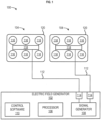
- FIG. 1 shows an example apparatus 100 for electrotherapeutic treatment.
- the apparatus 100 may be a portable, battery or power supply operated device which produces alternating electric fields within the body by means of non-invasive surface transducer arrays.
- the apparatus 100 may comprise an electric field generator 102 and one or more transducer arrays 104.
- the apparatus 100 may be configured to generate tumor treatment fields (TTFields) (e.g., at 150 kHz) via the electric field generator 102 and deliver the TTFields to an area of the body through the one or more transducer arrays 104.
- the electric field generator 102 may be a battery and/or power supply operated device.
- the one or more transducer arrays 104 are uniformly shaped. In an embodiment, the one or more transducer arrays 104 are not uniformly shaped.
- the electric field generator 102 may comprise a processor 106 in communication with a signal generator 108.
- the electric field generator 102 may comprise control software 110 configured for controlling the performance of the processor 106 and the signal generator 108.
- the signal generator 108 may generate one or more electric signals in the shape of waveforms or trains of pulses.
- the signal generator 108 may be configured to generate an alternating voltage waveform at frequencies in the range from about 50 kHz to about 500 kHz (preferably from about 100 kHz to about 300 kHz) (e.g., the TTFields).
- the voltages are such that the electric field intensity in tissue to be treated is in the range of about 0.1 V/cm to about 10 V/cm.
- One or more outputs 114 of the electric field generator 102 may be coupled to one or more conductive leads 112 that are attached at one end thereof to the signal generator 108.
- the opposite ends of the conductive leads 112 are connected to the one or more transducer arrays 104 that are activated by the electric signals (e.g., waveforms).
- the conductive leads 112 may comprise standard isolated conductors with a flexible metal shield and can grounded to prevent the spread of the electric field generated by the conductive leads 112.
- the one or more outputs 114 may be operated sequentially.
- Output parameters of the signal generator 108 may comprise, for example, an intensity of the field, a frequency of the waves (e.g., treatment frequency), and a maximum allowable temperature of the one or more transducer arrays 104.
- the output parameters may be set and/or determined by the control software 110 in conjunction with the processor 106. After determining a desired (e.g., optimal) treatment frequency, the control software 110 may cause the processor 106 to send a control signal to the signal generator 108 that causes the signal generator 108 to output the desired treatment frequency to the one or more transducer arrays 104.
- a desired (e.g., optimal) treatment frequency the control software 110 may cause the processor 106 to send a control signal to the signal generator 108 that causes the signal generator 108 to output the desired treatment frequency to the one or more transducer arrays 104.
- the one or more transducer arrays 104 may be configured in a variety of shapes and positions to generate an electric field of the desired configuration, direction, and intensity at a target volume to focus treatment.
- the one or more transducer arrays 104 may be configured to deliver two perpendicular field directions through a volume of interest.
- the one or more transducer arrays 104 arrays may comprise one or more electrodes 116.
- the one or more electrodes 116 may be made from any material with a high dielectric constant.
- the one or more electrodes 116 may comprise, for example, one or more insulated ceramic discs.
- the electrodes 116 may be biocompatible and coupled to a flexible circuit board 118.
- the electrodes 116 may be configured to not come into direct contact with the skin as the electrodes 116 are separated from the skin by a layer of conductive hydrogel (not shown) (similar to that found on electrocardiogram pads).
- the electrodes 116, the hydrogel, and the flexible circuit board 118 may be attached to a hypoallergenic medical adhesive bandage 120 to keep the one or more transducer arrays 104 in place on the body and in continuous direct contact with the skin.
- Each transducer array 104 may comprise one or more thermistors (not shown), for example, 8 thermistors, (accuracy ⁇ 1°C ) to measure skin temperature beneath the transducer arrays 104.
- the thermistors may be configured to measure skin temperature periodically, for example, every second.
- the thermistors may be read by the control software 110 while the TTFields are not being delivered to avoid any interference with the temperature measurements.
- the control software 110 can increase current until the current reaches maximal treatment current (for example, 4 Amps peak-to-peak). If the temperature reaches Tmax + 0.3°C and continues to rise, the control software 110 can lower the current. If the temperature rises to 41°C, the control software 110 can shut off the TTFields therapy and an overheating alarm can be triggered.
- Tmax a pre-set maximum temperature
- maximal treatment current for example, 4 Amps peak-to-peak
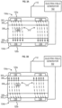
- the one or more transducer arrays 104 may vary in size and may comprise varying numbers of electrodes 116, based on patient body sizes and/or different therapeutic treatments.
- small transducer arrays may comprise 13 electrodes each
- large transducer arrays may comprise 20 electrodes each, with the electrodes serially interconnected in each array.
- each transducer array may comprise 9 electrodes each, with the electrodes serially interconnected in each array.
- transducer arrays 104 are contemplated and may also be used, including, for example, transducer arrays that use ceramic elements that are not disc-shaped, and transducer arrays that use non-ceramic dielectric materials positioned over a plurality of flat conductors. Examples of the latter include polymer films disposed over pads on a printed circuit board or over flat pieces of metal. Transducer arrays that use electrode elements that are not capacitively coupled may also be used. In this situation, each element of the transducer array would be implemented using a region of a conductive material that is configured for placement against a subject/patient's body, with no insulating dielectric layer disposed between the conductive elements and the body.
- transducer arrays may also be used. Any transducer array (or similar device/component) configuration, arrangement, type, and/or the like may be used for the methods and systems described herein as long as the transducer array (or similar device/component) configuration, arrangement, type, and/or the like is (a) capable of delivering TTFields to a subject/patient's body and (b) and may be positioned arranged, and/or placed on a portion of a patient/subject's body as described herein.
- Status of the apparatus 100 and monitored parameters may be stored a memory (not shown) and can be transferred to a computing device over a wired or wireless connection.
- the apparatus 100 may comprise a display (not shown) for displaying visual indicators, such as, power on, treatment on, alarms, and low battery.
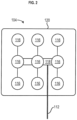
- FIG. 3A and FIG. 3B illustrate an example application of the apparatus 100.
- a transducer array 104a and a transducer array 104b are shown, each incorporated into a hypoallergenic medical adhesive bandage 120a and 120b, respectively.
- the hypoallergenic medical adhesive bandages 120a and 120b are applied to skin surface 302.
- a tumor 304 is located below the skin surface 302 and bone tissue 306 and is located within brain tissue 308.
- the electric field generator 102 causes the transducer array 104a and the transducer array 104b to generate alternating electric fields 310 within the brain tissue 308 that disrupt rapid cell division exhibited by cancer cells of the tumor 304.
- the alternating electric fields 310 have been shown in non-clinical experiments to arrest the proliferation of tumor cells and/or to destroy them.
- the alternating electric fields 310 takes advantage of the special characteristics, geometrical shape, and rate of dividing cancer cells, which make them susceptible to the effects of the alternating electric fields 310.
- the alternating electric fields 310 alter their polarity at an intermediate frequency (on the order of 100-300 kHz).
- the frequency used for a particular treatment may be specific to the cell type being treated (e.g., 150 kHz for MPM).
- the alternating electric fields 310 have been shown to disrupt mitotic spindle microtubule assembly and to lead to dielectrophoretic dislocation of intracellular macromolecules and organelles during cytokinesis. These processes lead to the physical disruption of the cell membrane and programmed cell death (apoptosis).
- alternating electric fields 310 may be delivered through two pairs of transducer arrays 104 that generate perpendicular fields within the treated tumor.
- Theory and modeling predict that the directional, tumor-killing effect of the alternating electric fields 310 is due to their disruption of cellular structures whose spatial orientation renders them maximally susceptible to the disruptive effect when they are parallel to the alternating electric fields 310.
- theory and modeling predict that changing the direction of the alternating electric fields 310 multiple times in specific directions will have the maximal disruptive effect on the cellular structures, with each added change of direction reducing the variance of electric field strength received by the cellular structure.
- one pair of transducer arrays 104 may be located to the left and right (LR) of the tumor, and the other pair of transducer arrays 104 may be located anterior and posterior (AP) to the tumor.
- the alternating electric fields 310 may be delivered according to a symmetric setup of transducer arrays 104 (e.g., four total transducer arrays 104, two matched pairs). In another embodiment, the alternating electric fields 310 may be delivered according to an asymmetric setup of transducer arrays 104 (e.g., three total transducer arrays 104 ).
- An asymmetric setup of transducer arrays 104 may engage two of the three transducer arrays 104 to deliver the alternating electric fields 310 and then switch to another two of the three transducer arrays 104 to deliver the alternating electric fields 310, and the like.
- subsets of transducer arrays 104 may be used to achieve more changes of direction of the alternating electric fields 310 than are possible by using the full transducer array 104 in each location.
- the changes of direction of electric fields 310 via transducer arrays, or their subset transducers would attempt to attain the following angles for each number of directions: 90 degrees in two dimensions for two directions, 90 degrees in three directions, all orthogonal to each other, in three dimensions, and the dihedral angle of the tetrahedron ( ⁇ 70.53 degrees) in three dimensions with four changes.
- Electric fields may heat tissue (e.g., the skin surface 302, etc.) under and/or near transducers.
- tissue e.g., the skin surface 302, etc.
- the conductivity of tissues may vary according to orientation to an imposed field causing inhomogeneous concentrations of field strength.
- an electric field may be reduced in strength and efficacy (e.g., shunted, etc.) due to the presence of conductive body fluids such as cerebrospinal fluid (CSF).
- the apparatus 100 may be configured to reduce and/or eliminate instances of tissue heating at the tranducer-tissue interface.
- the apparatus 100 may be configured to cyclically activate and deactivate electrodes of a transducer array to alter the direction and/or duration of an electric field (e.g., to impose alignment or orthogonality with cell axes within a region-or interest (ROI)) and reduce high-temperature points at the transducer-skin interface by allowing deactivated electrodes to cool to the desired temperature, such as a threshold temperature.
- An optimal interval at which to alter field direction may be determined by analysis of a tissue model that includes tissue/information from a plurality of patients.
- Optimal parameters for field strength, frequency, and duration may be determined according to variations in the geometry of various tissue samples the electric field generator 102 may be configured to 'sweep' through various parameter ranges and determine the effect of the parameters on an efficacious dose at a target ROI (e.g., tumor, etc.).
- a target ROI e.g., tumor, etc.
- a random selection of angles at optimal duty cycles determined by the electric field generator 102 such as a 50 ms duty cycle and/or a or temperature-limited duty cycle, may optimize the average therapeutic dose delivered to a target ROI (e.g., tumor, etc.).
- the electric field generator 102 may activate/deactivate cathode and anode combinations of the transducer arrays 104 based on the location/placement of the transducer arrays 104 and relative orientation to the geometric center of the target ROI.
- the apparatus 100 may include one or more thermistors that indicate the temperature state of the one or more electrodes 116 of the transducer arrays 104.
- a feedback loop may be established between the one or more thermistors and the processor 106 and/or the control software 110.
- the electric field generator 102 based on the feedback loop, may be configured to optimally maximize current and/or voltage delivered to the transducer arrays 104 by cycling patterns of electric field amplitude changes at fixed or variable cycle lengths.
- the electric field generator 102 may cyclically and simultaneously deactivate (e.g., turn off amplitude, etc.) one or more electrodes of the transducer arrays 104 with the highest sensed temperatures and activate (e.g., turn on amplitude, etc.) one or more electrodes of the transducer arrays 104 according to a function of electrode temperature and an available selection of angles between electrodes of the transducer arrays 104.
- the function of electrode temperature and interelectrode angle may be a weighted product of temperature multiplied by a function of the angle between the difference in temperature between two electrodes and an angle between lines drawn from centers of the two electrodes to the geometric center of a target ROI.
- electrodes of the transducer arrays 104 may be activated for durations of decreasing increments such that the temperature of the activated electrodes approaches an asymptotic limit.
- the decreasing increments of the durations may be based on a difference between the asymptotic limit and the temperature of the activated electrodes at a given point in time.
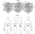
- the transducer arrays 104 may be placed on a patient's head. As shown in FIG. 4B , the transducer arrays 104 may be placed on a patient's abdomen. As shown in FIG. 5A , the transducer arrays 104 may be placed on a patient's torso. As shown in FIG. 5B , the transducer arrays 104 may be placed on a patient's pelvis. Placement of the transducer arrays 104 on other portions of a patient's body (e.g., arm, leg, etc.) are specifically contemplated.
- a patient's body e.g., arm, leg, etc.
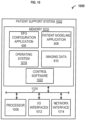
- FIG. 6 is a block diagram depicting non-limiting examples of a system 600 comprising a patient support system 602.
- the patient support system 602 can comprise one or multiple computers configured to operate and/or store an electric field generator (EFG) configuration application 606, a patient modeling application 608, and/or imaging data 610.
- EFG electric field generator
- the patient support system 602 can comprise, for example, a computing device.
- the patient support system 602 can comprise, for example, a laptop computer, a desktop computer, a mobile phone (e.g., a smartphone), a tablet, and the like.
- the patient modeling application 608 may be configured to generate a three dimensional model of a portion of a body of a patient (e.g., a patient model) according to the imaging data 610.
- the imaging data 610 may comprise any type of visual data, for example, single-photon emission computed tomography (SPECT) image data, x-ray computed tomography (x-ray CT) data, magnetic resonance imaging (MRI) data, positron emission tomography (PET) data, data that can be captured by an optical instrument (e.g., a photographic camera, a charge-coupled device (CCD) camera, an infrared camera, etc.), and the like.
- SPECT single-photon emission computed tomography
- x-ray CT x-ray computed tomography
- MRI magnetic resonance imaging
- PET positron emission tomography
- an optical instrument e.g., a photographic camera, a charge-coupled device (CCD) camera, an infrared camera, etc.
- image data may include 3D data obtained from or generated by a 3D scanner (e.g., point cloud data).
- the patient modeling application 608 may also be configured to generate a three-dimensional array layout map based on the patient model and one or more electric field simulations.
- the imaging data 610 may be analyzed by the patient modeling application 608 to identify a region of interest that comprises a tumor.
- the imaging frameworks based on anatomical head models using Finite Element Method (FEM) simulations may be used. These simulations yield realistic head models based on magnetic resonance imaging (MRI) measurements and compartmentalize tissue types such as skull, white matter, gray matter, and cerebrospinal fluid (CSF) within the head.
- MRI magnetic resonance imaging
- CSF cerebrospinal fluid
- Each tissue type may be assigned dielectric properties for relative conductivity and permittivity, and simulations may be run whereby different transducer array configurations are applied to the surface of the model to understand how an externally applied electric field, of preset frequency, will distribute throughout any portion of a patient's body, for example, the brain.
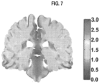
- the results of these simulations employing paired array configurations, a constant current, and a preset frequency of 200 kHz, have demonstrated that electric field distributions are relatively non-uniform throughout the brain and that electric field intensities exceeding 1 V/cm are generated in most tissue compartments except CSF. These results are obtained assuming total currents with a peak-to-peak value of 1800 milliamperes (mA) at the transducer array-scalp interface.
- mA milliamperes
- FIG. 7 illustrates electric field magnitude and distribution (in V/cm) shown in the coronal view from a finite element method simulation model. This simulation employs a left-right paired transducer array configuration.
- the patient modeling application 608 may be configured to determine a desired (e.g., optimal) transducer array layout for a patient based on the location and extent of the tumor. For example, initial morphometric head size measurements may be determined from the T1 sequences of a brain MRI, using axial and coronal views. Postcontrast axial and coronal MRI slices may be selected to demonstrate the maximal diameter of enhancing lesions. Employing measures of head size and distances from predetermined fiducial markers to tumor margins, varying permutations, and combinations of paired array layouts may be assessed to generate the configuration which delivers maximal electric field intensity to the tumor site. As shown in FIG. 8A , the output may be a three-dimensional array layout map 800. The three-dimensional array layout map 800 may be used by the patient and/or caregiver in arranging arrays on the scalp during the normal course of TTFields therapy as shown in FIG. 8B .
- the patient modeling application 608 can be configured to determine the three-dimensional array layout map for a patient.
- MRI measurements of the portion of the patient that is to receive the transducer arrays may be determined.
- the MRI measurements may be received via a standard Digital Imaging and Communications in Medicine (DICOM) viewer.
- DICOM Digital Imaging and Communications in Medicine
- MRI measurement determination may be performed automatically, for example by way of artificial intelligence techniques, or may be performed manually, for example by way of a physician.
- Manual MRI measurement determination may comprise receiving and/or providing MRI data via a DICOM viewer.
- the MRI data may comprise scans of the portion of the patient that contains a tumor.
- the MRI data may comprise scans of the head that comprise one or more of a right frontotemporal tumor, a right parieto-temporal tumor, a left frontotemporal tumor, a left parieto-occipital tumor, and/or a multi-focal midline tumor.
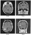
- FIG. 9A, FIG. 9B, FIG. 9C, and FIG. 9D show example MRI data showing scans of the head of a patient.
- FIG. 9A, FIG. 9B, FIG. 9C, and FIG. 9D show example MRI data showing scans of the head of a patient.
- FIG. 9A shows an axial T1 sequence slice containing the most apical image, including orbits used to measure head size.
- FIG. 9B shows a coronal T1 sequence slice selecting image at the level of ear canal used to measure head size.
- FIG. 9C shows a postcontrast T1 axial image shows maximal enhancing tumor diameter used to measure tumor location.
- FIG. 9D shows a postcontrast T1 coronal image shows maximal enhancing tumor diameter used to measure tumor location.
- MRI measurements may commence from fiducial markers at the outer margin of the scalp and extend tangentially from a right-, anterior-, superior origin. Morphometric head size may be estimated from the axial T1 MRI sequence selecting the most apical image which still included the orbits (or the image directly above the superior edge of the orbits)
- the MRI measurements may comprise, for example, one or more head size measurements and/or tumor measurements.
- one or more MRI measurements may be rounded to the nearest millimeter and may be provided to a transducer array placement module (e.g., software) for analysis. The MRI measurements may then be used to generate the three-dimensional array layout map (e.g., three-dimensional array layout map 800 ).
- the MRI measurements may comprise one or more head size measurements such as: a maximal anteroposterior (A-P) head size, commencing measurement from the outer margin of the scalp; a maximal width of the head perpendicular to the A-P measurement: right to left lateral distance; and/or a distance from the far most right margin of the scalp to the anatomical midline.
- A-P anteroposterior
- the MRI measurements may comprise one or more head size measurements such as coronal view head size measurements.
- Coronal view head size measurements may be obtained on the T1 MRI sequence selecting the image at the level of the ear canal ( FIG. 9B ).
- the coronal view head size measurements may comprise one or more of: a vertical measurement from the apex of the scalp to an orthogonal line delineating the inferior margin of the temporal lobes; a maximal right to left lateral head width; and/or a distance from the far right margin of the scalp to the anatomical midline.
- the MRI measurements may comprise one or more tumor measurements, such as tumor location measurements.
- the tumor location measurements may be made using T1 postcontrast MRI sequences, firstly on the axial image demonstrating maximal enhancing tumor diameter ( FIG. 9C ).
- the tumor location measurements may comprise one or more of: a maximal A-P head size, excluding the nose; a maximal right to left lateral diameter, measured perpendicular to the A-P distance; a distance from the right margin of the scalp to the anatomical midline; a distance from the right margin of the scalp to the closest tumor margin, measured parallel to the right-left lateral distance and perpendicular to the A-P measurement; a distance from the right margin of the scalp to the farthest tumor margin, measured parallel to the right-left lateral distance, perpendicular to the A-P measurement; a distance from the front of the head, measured parallel to the A-P measurement, to the closest tumor margin; and/or a distance from the front of the head, measured parallel to the A-P measurement, to the
- the one or more tumor measurements may comprise coronal view tumor measurements.
- the coronal view tumor measurements may comprise identifying the postcontrast T1 MRI slice featuring the maximal diameter of tumor enhancement ( FIG. 9D ).
- the coronal view tumor measurements may comprise one or more of: a maximal distance from the apex of the scalp to the inferior margin of the cerebrum.
- MRI measurements may be used, particularly when the tumor is present in another portion of the patient's body.
- the MRI measurements may be used by the patient modeling application 608 to generate a patient model.
- the patient model may then be used to determine the three-dimensional array layout map (e.g., three-dimensional array layout map 800).
- a healthy head model may be generated which serves as a deformable template from which patient models can be created.
- the tumor may be segmented from the patient's MRI data (e.g., the one or more MRI measurements). Segmenting the MRI data identifies the tissue type in each voxel, and electric properties may be assigned to each tissue type based on empirical data. Table 1 shows standard electrical properties of tissues that may be used in simulations.
- the region of the tumor in the patient MRI data may be masked, and non-rigid registration algorithms may be used to register the remaining regions of the patient head on to a 3D discrete image representing the deformable template of the healthy head model.
- This process yields a non-rigid transformation that maps the healthy portion of the patient's head in to the template space, as well as the inverse transformation that maps the template in to the patient space.
- the inverse transformation is applied to the 3D deformable template to yield an approximation of the patient head in the absence of a tumor.
- the tumor referred to as a region-of-interest (ROI)
- ROI region-of-interest
- the patient model may be a digital representation in three dimensional space of the portion of the patient's body, including internal structures, such as tissues, organs, tumors, etc.
- Table 1 Tissue Type Conductivity, S/m Relative Permittivity Scalp 0.3 5000 Skull 0.08 200 Cerebrospinal fluid 1.79 110 Gray matter 0.25 3000 White matter 0.12 2000 Enhancing tumor 0.24 2000 Enhancing nontumor 0.36 1170 Resection cavity 1.79 110 Necrotic tumor 1 110 Hematoma 0.3 2000 Ischemia 0.18 2500 Atrophy 1 110 Air 0 0 0
- TTFields Delivery of TTFields may then be simulated by the patient modeling application 608 using the patient model. Simulated electric field distributions, dosimetry, and simulation-based analysis are described in U.S. Patent Publication No. 20190117956 A1 and Publication " Correlation of Tumor treating Fields Dosimetry to Survival Outcomes in Newly Diagnosed Glioblastoma: A Large-Scale Numerical Simulation-based Analysis of Data from the Phase 3 EF-14 randomized Trial” by Ballo, et al. (2019 ).
- a reference coordinate system may be defined.
- a transversal plane may initially be defined by conventional LR and AP positioning of the transducer arrays.
- the left-right direction may be defined as the x-axis
- the AP direction may be defined as the y-axis
- the craniocaudal direction normal to the XY-plane may be defined as the Z-axis.
- transducer arrays may be virtually placed on the patient model with their centers and longitudinal axes in the XY-plane.
- a pair of transducer arrays may be systematically rotated around the z-axis of the head model, e.g., in the XY-plane, from 0 to 180 degrees, thereby covering the entire circumference of the head (by symmetry).
- the rotation interval may be, for example, 15 degrees, corresponding to approximately 2 cm translations, giving a total of twelve different positions in the range of 180 degrees. Other rotation intervals are contemplated.
- Electric field distribution calculations may be performed for each transducer array position relative to tumor coordinates.
- Electric field distribution in the patient model may be determined by the patient modeling application 608 using a finite element (FE) approximation of electrical potential.
- FE finite element
- the quantities defining a time-varying electromagnetic field are given by the complex Maxwell equations.
- Dirichlet boundary conditions were used with the electric potential was set to (arbitrarily chosen) fixed values at each set of electrode arrays.
- the electric (vector) field was calculated as the numerical gradient of the electric potential and the current density (vector field) was computed from the electric field using Ohm's law.
- the potential difference of the electric field values and the current densities were linearly rescaled to ensure a total peak-to-peak amplitude for each array pair of 1.8 A, calculated as the (numerical) surface integral of the normal current density components over all triangular surface elements on the active electrode discs. This corresponds to the current level used for clinical TTFields therapy by the Optune ® device.
- the "dose” of TTFields was calculated as the intensity (L2 norm) of the field vectors.
- the modeled current is assumed to be provided by two separate and sequentially active sources each connected to a pair of 3x3 transducer arrays.
- the left and posterior arrays may be defined to be sources in the simulations, while the right and anterior arrays were the corresponding sinks, respectively.
- this choice is arbitrary and does not influence the results.
- An average electric field strength generated by transducer arrays placed at multiple locations on the patient may be determined by the patient modeling application 608 for one or more tissue types.
- the transducer array position that corresponds to the highest average electric field strength in the tumor tissue type(s) may be selected as a desired (e.g., optimal) transducer array position for the patient.
- one or more candidate positions for a transducer array(s) may be excluded as a result of a physical condition of the patient. For example, one or more candidate positions may be excluded based on areas of skin irritation, scars, surgical sites, discomfort, etc.
- the transducer array position that corresponds to the highest average electric field strength in the tumor tissue type(s), after excluding one or more candidate positions, may be selected as a desired (e.g., optimal) transducer array position for the patient.
- a transducer array position may be selected that results in less than the maximum possible average electric field strength.
- the patient model may be modified to include an indication of the desired transducer array position.
- the resulting patient model comprising the indication(s) of the desired transducer array position(s), may be referred to as the three-dimensional array layout map (e.g., three-dimensional array layout map 600 ).
- the three-dimensional array layout map may thus comprise a digital representation, in three-dimensional space, of the portion of the patient's body, an indication of tumor location, an indication of a position for placement of one or more transducer arrays, combinations thereof, and the like.
- the three-dimensional array layout map may be provided to the patient in a digital form and/or a physical form.
- the patient, and/or a patient caregiver, may use the three-dimensional array layout map to affix one or more transducer arrays to an associated portion of the patient's body (e.g., head).
- FIG. 10 is a block diagram depicting an environment 1000 comprising a non-limiting example of the patient support system 104. In an aspect, some or all steps of any described method may be performed on a computing device as described herein.
- the patient support system 104 can comprise one or multiple computers configured to store one or more of the EFG configuration application 606, the patient modeling application 608, the imaging data 610, and the like.
- the patient support system 104 can be a digital computer that, in terms of hardware architecture, generally includes a processor 1008, memory system 1010, input/output (I/O) interfaces 1012, and network interfaces 1014. These components ( 1008, 1010, 1012, and 1014 ) are communicatively coupled via a local interface 1016.
- the local interface 1016 can be, for example, but not limited to, one or more buses or other wired or wireless connections, as is known in the art.
- the local interface 1016 can have additional elements, which are omitted for simplicity, such as controllers, buffers (caches), drivers, repeaters, and receivers, to enable communications. Further, the local interface may include address, control, and/or data connections to enable appropriate communications among the aforementioned components.
- the processor 1008 can be a hardware device for executing software, particularly that stored in memory system 1010.
- the processor 1008 can be any custom made or commercially available processor, a central processing unit (CPU), an auxiliary processor among several processors associated with the patient support system 1002, a semiconductor-based microprocessor (in the form of a microchip or chipset), or generally any device for executing software instructions.
- the processor 1008 can be configured to execute software stored within the memory system 1010, to communicate data to and from the memory system 1010, and to generally control operations of the patient support system 1002 pursuant to the software.
- the I/O interfaces 1012 can be used to receive user input from and/or for providing system output to one or more devices or components.
- User input can be provided via, for example, a keyboard and/or a mouse.
- System output can be provided via a display device and a printer (not shown).
- I/O interfaces 1012 can include, for example, a serial port, a parallel port, a Small Computer System Interface (SCSI), an IR interface, an RF interface, and/or a universal serial bus (USB) interface.
- the network interface 1014 can be used to transmit and receive from the patient support system 1002.
- the network interface 1014 may include, for example, a 10BaseT Ethernet Adaptor, a 100BaseT Ethernet Adaptor, a LAN PHY Ethernet Adaptor, a Token Ring Adaptor, a wireless network adapter (e.g., WiFi), or any other suitable network interface device.
- the network interface 1014 may include address, control, and/or data connections to enable appropriate communications.
- the memory system 1010 can include any one or combination of volatile memory elements (e.g., random access memory (RAM, such as DRAM, SRAM, SDRAM, etc.)) and nonvolatile memory elements (e.g., ROM, hard drive, tape, CDROM, DVDROM, etc.). Moreover, the memory system 1010 may incorporate electronic, magnetic, optical, and/or other types of storage media. Note that the memory system 1010 can have a distributed architecture, where various components are situated remote from one another, but can be accessed by the processor 1008.
- the software in memory system 1010 may include one or more software programs, each of which comprises an ordered listing of executable instructions for implementing logical functions.
- the software in the memory system 1010 of the patient support system 1002 can comprise the EFG configuration application 606, the patient modeling application 608, the imaging data 610, and a suitable operating system (O/S) 1018.
- the operating system 1018 essentially controls the execution of other computer programs, and provides scheduling, input-output control, file and data management, memory management, and communication control and related services.
- EFG configuration application 606, the patient modeling application 608, the imaging data 610, and/or the control software 110 can be stored on or transmitted across some form of computer readable media. Any of the disclosed methods can be performed by computer readable instructions embodied on computer readable media.
- Computer readable media can be any available media that can be accessed by a computer.
- Computer readable media can comprise “computer storage media” and “communications media.”
- “Computer storage media” can comprise volatile and nonvolatile, removable and non-removable media implemented in any methods or technology for storage of information such as computer readable instructions, data structures, program modules, or other data.
- Exemplary computer storage media can comprise RAM, ROM, EEPROM, flash memory or other memory technology, CD-ROM, digital versatile disks (DVD) or other optical storage, magnetic cassettes, magnetic tape, magnetic disk storage or other magnetic storage devices, or any other medium which can be used to store the desired information and which can be accessed by a computer.
- one or more of the apparatus 100, the patient support system 602, the patient modeling application 608, and/any other device/component described herein can be configured to perform a method 1100 comprising, at 1110, causing cyclical application of a first electric field via a first transducer array in a first direction and a second electric field via a second transducer array in a second direction, opposite the first direction, wherein the first transducer array comprises a first plurality of electrodes and the second transducer array comprises a second plurality of electrodes.
- the first electric field and the second electric field may be applied with a frequency between 50 and 500 kHz and electric field strength of at least 1 V/cm to a tumor.
- the cyclical application may include applying the first electric field for between 20 and 500 ms in the first direction and the second electric field for between 20 and 500 ms in the second direction during each cycle.
- the method 1100 includes, during the cyclical application, at 1120, deactivating, based on a temperature associated with the one or more electrodes of the first plurality of electrodes or one or more electrodes of the second plurality of electrodes satisfying a threshold, the one or more electrodes of the first plurality of electrodes or the one or more electrodes of the second plurality of electrodes, and at 1130, activating, based on a temperature associated with the deactivated one or more electrodes of the first plurality of electrodes or the deactivated one or more electrodes of the second plurality of electrodes no longer satisfying the threshold, the deactivated one or more electrodes of the first plurality of electrodes or the deactivated one or more electrodes of the second plurality of electrodes.
- the method 1100 includes determining that the temperature associated with the one or more electrodes of the first plurality of electrodes or the one or more electrodes of the second plurality of electrodes satisfies the threshold.
- the method 1100 includes determining that the temperature associated with the deactivated one or more electrodes of the first plurality of electrodes or the deactivated one or more electrodes of the second plurality of electrodes no longer satisfies the threshold.
- the method 1100 may include, during the cyclical application, selectively deactivating, one or more electrodes of the first plurality of electrodes or one or more electrodes of the second plurality of electrodes, to adjust an angle at which the first electric field or the second electric field is applied to the region of interest.
- selectively deactivating the one or more electrodes of the first plurality of electrodes or the one or more electrodes of the second plurality of electrodes may be based on a random selection of angles at an optimal duty cycle.
- selectively deactivating the one or more electrodes of the first plurality of electrodes or the one or more electrodes of the second plurality of electrodes may be based on a random selection of angles at a temperature-limited duty cycle.
- selectively deactivating the one or more electrodes of the first plurality of electrodes or the one or more electrodes of the second plurality of electrodes may be based on the selection of angles that are orthogonal relative to a geometric center of the region of interest. In some instances, selectively deactivating the one or more electrodes of the first plurality of electrodes or the one or more electrodes of the second plurality of electrodes may be based on the selection of angles that are orthogonal relative to pairs of cathode electrodes and anode electrodes that are orthogonal to each other. In some instances, selectively deactivating the one or more electrodes of the first plurality of electrodes or the one or more electrodes of the second plurality of electrodes may be based on the selection of angles that are most distant from previous angles used within a current duty cycle.
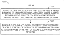
- one or more of the apparatus 100, the patient support system 602, the patient modeling application 608, and/any other device/component described herein can be configured to perform a method 1200 comprising, at 1210, causing cyclical application of a first electric field via a first transducer array in a first direction and a second electric field via a second transducer array in a second direction, opposite the first direction, to a region of interest, wherein the first transducer array comprises a first plurality of electrodes and the second transducer array comprises a second plurality of electrodes.
- selectively deactivating, one or more electrodes of the first plurality of electrodes or one or more electrodes of the second plurality of electrodes to adjust an angle at which the first electric field or the second electric field is applied to the region of interest.
- selectively deactivating the one or more electrodes of the first plurality of electrodes or the one or more electrodes of the second plurality of electrodes may be based on a random selection of angles at an optimal duty cycle.
- selectively deactivating the one or more electrodes of the first plurality of electrodes or the one or more electrodes of the second plurality of electrodes may be based on a random selection of angles at a temperature-limited duty cycle.
- selectively deactivating the one or more electrodes of the first plurality of electrodes or the one or more electrodes of the second plurality of electrodes may be based on the selection of angles that are orthogonal relative to a geometric center of the region of interest.
- selectively deactivating the one or more electrodes of the first plurality of electrodes or the one or more electrodes of the second plurality of electrodes may be based on the selection of angles that are orthogonal relative to pairs of cathode electrodes and anode electrodes that are orthogonal to each other.
- selectively deactivating the one or more electrodes of the first plurality of electrodes or the one or more electrodes of the second plurality of electrodes may be based on the selection of angles that are most distant from previous angles used within a current duty cycle.
- the method 1200 includes, during the cyclical application, deactivating, based on a temperature associated with the one or more electrodes of the first plurality of electrodes or the one or more electrodes of the second plurality of electrodes satisfying a threshold, the one or more electrodes of the first plurality of electrodes or the one or more electrodes of the second plurality of electrodes, and activating, based on a temperature associated with the deactivated one or more electrodes of the first plurality of electrodes or the deactivated one or more electrodes of the second plurality of electrodes no longer satisfying the threshold, the deactivated one or more electrodes of the first plurality of electrodes or the deactivated one or more electrodes of the second plurality of electrodes.
- selectively deactivating the one or more electrodes of the first plurality of electrodes or the one or more electrodes of the second plurality of electrodes may be based on a random selection of angles at an optimal duty cycle and a temperature associated deactivation state of one or more electrodes.
- selectively deactivating the one or more electrodes of the first plurality of electrodes or the one or more electrodes of the second plurality of electrodes may be based on a random selection of angles at a temperature-limited duty cycle and a temperature associated deactivation state of one or more electrodes.
- selectively deactivating the one or more electrodes of the first plurality of electrodes or the one or more electrodes of the second plurality of electrodes may be based on the selection of angles that are orthogonal relative to a geometric center of the region of interest and a temperature associated deactivation state of one or more electrodes.
- selectively deactivating the one or more electrodes of the first plurality of electrodes or the one or more electrodes of the second plurality of electrodes may be based on the selection of angles that are orthogonal relative to pairs of cathode electrodes and anode electrodes that are orthogonal to each other and a temperature associated deactivation state of one or more electrodes.
- selectively deactivating the one or more electrodes of the first plurality of electrodes or the one or more electrodes of the second plurality of electrodes may be based on the selection of angles that are most distant from previous angles used within a current duty cycle.
- selectively deactivating the one or more electrodes of the first plurality of electrodes or the one or more electrodes of the second plurality of electrodes may be based on a weighted product of temperature multiplied by a function of the angle between the temperature difference.
Landscapes
- Health & Medical Sciences (AREA)
- Life Sciences & Earth Sciences (AREA)
- Engineering & Computer Science (AREA)
- Biomedical Technology (AREA)
- Nuclear Medicine, Radiotherapy & Molecular Imaging (AREA)
- Radiology & Medical Imaging (AREA)
- Animal Behavior & Ethology (AREA)
- General Health & Medical Sciences (AREA)
- Public Health (AREA)
- Veterinary Medicine (AREA)
- Hospice & Palliative Care (AREA)
- Oncology (AREA)
- Biophysics (AREA)
- Heart & Thoracic Surgery (AREA)
- Magnetic Resonance Imaging Apparatus (AREA)
- Control Of Heat Treatment Processes (AREA)
- Control Of Temperature (AREA)
- Electrotherapy Devices (AREA)
- Non-Silver Salt Photosensitive Materials And Non-Silver Salt Photography (AREA)
- Investigating Or Analyzing Materials By The Use Of Electric Means (AREA)
- Inert Electrodes (AREA)
- Crystals, And After-Treatments Of Crystals (AREA)
Claims (6)
- Vorrichtung zur elektrotherapeutischen Behandlung eines Bereiches von Interesse, welche umfasst:eine erste und eine zweite Wandleranordnung (104), worin die erste Wandleranordnung (104) mehrere erste Elektroden (1 16) umfasst und die zweite Wandleranordnung (104) mehrere zweite Elektroden (116) umfasst; undeinen elektrischen Feldgenerator (102), der ausgestaltet ist, ein zyklisches Anlegen eines ersten und eines zweiten elektrischen Feldes in einer ersten und einer zweiten, unterschiedlichen Richtung über die erste und die zweite Wandleranordnung (104) an einen Bereich von Interesse zu bewirken;dadurch gekennzeichnet, dass während des zyklischen Anlegens, basierend auf einer Temperatur, die mit einer oder mehreren Elektroden (116) der mehreren ersten Elektroden (116) oder einer oder mehreren Elektroden (116) der mehreren zweiten Elektroden (116) verbunden ist, eine oder mehrere Elektroden (116, ) der mehreren ersten Elektroden (116) oder eine oder mehrere Elektroden (116) der mehreren zweiten Elektroden (116), die einen Schwellenwert erfüllen, selektiv deaktiviert werden und eine oder mehrere Elektroden (116) der mehreren ersten Elektroden (116) oder eine oder mehrere Elektroden (116) der mehreren zweiten Elektroden (116), die den Schwellenwert nicht erfüllen, selektiv aktiviert werden, um einen Winkel einzustellen, mit dem das erste elektrische Feld oder das zweite elektrische Feld an den Bereich von Interesse angelegt wird.
- Vorrichtung nach Anspruch 1, worin die eine oder die mehreren Elektroden (116) der mehreren ersten Elektroden (116) oder die eine oder die mehreren Elektroden (116) der mehreren zweiten Elektroden (116) auf der Grundlage einer zufälligen Auswahl von Winkeln bei einem optimalen Arbeitszyklus selektiv deaktiviert werden.
- Vorrichtung nach Anspruch 1, worin die eine oder die mehreren Elektroden (116) der mehreren ersten Elektroden (116) oder die eine oder die mehreren Elektroden (116) der mehreren zweiten Elektroden (116) auf der Grundlage einer zufälligen Auswahl von Winkeln bei einem temperaturbegrenzten Arbeitszyklus selektiv deaktiviert werden.
- Vorrichtung nach Anspruch 1, worin die eine oder die mehreren Elektroden (116) der mehreren ersten Elektroden (116) oder die eine oder die mehreren Elektroden (116) der mehreren zweiten Elektroden (116) selektiv deaktiviert werden, basierend auf der Auswahl von Winkeln, die eines oder mehreres sind von: am weitesten entfernt von den vorhergehenden Winkeln, die innerhalb eines aktuellen Arbeitszyklus verwendet wurden, und orthogonal relativ zu einem geometrischen Zentrum des Bereiches von Interesse.
- Vorrichtung nach Anspruch 1, worin die eine oder die mehreren Elektroden (116) der mehreren ersten Elektroden (116) oder die eine oder die mehreren Elektroden (116) der mehreren zweiten Elektroden (116) selektiv deaktiviert werden, basierend auf der Auswahl von Winkeln, die eines oder mehreres sind von: am weitesten von den vorhergehenden Winkeln, die innerhalb eines aktuellen Arbeitszyklus verwendet werden, und orthogonal zu Paaren von Kathoden- und Anodenelektroden (116), die orthogonal zueinander stehen.
- Vorrichtung nach Anspruch 1, worin die eine oder die mehreren Elektroden (116) der mehreren ersten Elektroden (116) oder die eine oder die mehreren Elektroden (116) der mehreren zweiten Elektroden (116) selektiv deaktiviert werden, basierend auf einem gewichteten Produkt der Temperatur, multipliziert mit einer Funktion eines Winkels zwischen einer Temperaturdifferenz zwischen zwei Wandleranordnungen (104) und einem Winkel zwischen Linien, die von den Zentren der beiden Wandleranordnungen (104) zum geometrischen Zentrum der geschätzten Zielposition gezogen werden.
Applications Claiming Priority (4)
| Application Number | Priority Date | Filing Date | Title |
|---|---|---|---|
| US201962955747P | 2019-12-31 | 2019-12-31 | |
| US17/118,056 US12121739B2 (en) | 2019-12-31 | 2020-12-10 | Methods, systems, and apparatuses for managing temperatures induced by alternating fields |
| EP20870439.5A EP4051369A2 (de) | 2019-12-31 | 2020-12-29 | Verfahren, systeme und vorrichtungen zur verwaltung von durch wechselfelder induzierten temperaturen |
| PCT/IB2020/001142 WO2021136972A2 (en) | 2019-12-31 | 2020-12-29 | Methods, systems, and apparatuses for managing temperatures induced by alternating fields |
Related Parent Applications (2)
| Application Number | Title | Priority Date | Filing Date |
|---|---|---|---|
| EP20870439.5A Division-Into EP4051369A2 (de) | 2019-12-31 | 2020-12-29 | Verfahren, systeme und vorrichtungen zur verwaltung von durch wechselfelder induzierten temperaturen |
| EP20870439.5A Division EP4051369A2 (de) | 2019-12-31 | 2020-12-29 | Verfahren, systeme und vorrichtungen zur verwaltung von durch wechselfelder induzierten temperaturen |
Publications (3)
| Publication Number | Publication Date |
|---|---|
| EP4074366A1 EP4074366A1 (de) | 2022-10-19 |
| EP4074366C0 EP4074366C0 (de) | 2024-08-14 |
| EP4074366B1 true EP4074366B1 (de) | 2024-08-14 |
Family
ID=76545774
Family Applications (2)
| Application Number | Title | Priority Date | Filing Date |
|---|---|---|---|
| EP20870439.5A Withdrawn EP4051369A2 (de) | 2019-12-31 | 2020-12-29 | Verfahren, systeme und vorrichtungen zur verwaltung von durch wechselfelder induzierten temperaturen |
| EP22177338.5A Active EP4074366B1 (de) | 2019-12-31 | 2020-12-29 | Vorrichtungen zur verwaltung von durch wechselfelder induzierten temperaturen |
Family Applications Before (1)
| Application Number | Title | Priority Date | Filing Date |
|---|---|---|---|
| EP20870439.5A Withdrawn EP4051369A2 (de) | 2019-12-31 | 2020-12-29 | Verfahren, systeme und vorrichtungen zur verwaltung von durch wechselfelder induzierten temperaturen |
Country Status (11)
| Country | Link |
|---|---|
| US (2) | US12121739B2 (de) |
| EP (2) | EP4051369A2 (de) |
| JP (1) | JP2023508588A (de) |
| KR (1) | KR20220124198A (de) |
| CN (1) | CN114845767A (de) |
| AU (1) | AU2020416736A1 (de) |
| BR (1) | BR112022012962A2 (de) |
| CA (1) | CA3163318A1 (de) |
| IL (1) | IL294385B1 (de) |
| MX (1) | MX2022006219A (de) |
| WO (1) | WO2021136972A2 (de) |
Families Citing this family (8)
| Publication number | Priority date | Publication date | Assignee | Title |
|---|---|---|---|---|
| AU2017289870B2 (en) * | 2016-06-30 | 2021-12-23 | Novocure Gmbh | Arrays for longitudinal delivery of TTFields to a body |
| CN114534091B (zh) * | 2022-02-17 | 2022-09-09 | 湖南安泰康成生物科技有限公司 | 利用电场抑制肿瘤增殖的设备及其控制装置 |
| CN114724680A (zh) * | 2022-03-22 | 2022-07-08 | 河北普尼医疗科技有限公司 | 基于人工智能深度学习的治疗方法及系统 |
| US20240108892A1 (en) * | 2022-09-30 | 2024-04-04 | Novocure Gmbh | Changing the Orientation of Tumor Treating Fields (TTFields) by Adjusting the Amplitudes of Two or More Electric Fields that Are All In-Phase with Each Other |
| KR20240129583A (ko) | 2023-02-20 | 2024-08-27 | 주식회사 필드큐어 | 대상체에 전기장을 전달하는 임베디드 전극 |
| US20240325753A1 (en) * | 2023-03-31 | 2024-10-03 | Novocure Gmbh | Applying Tumor Treating Fields (TTFields) to a Body Part in at Least Three Different Directions Using Five Arrays of Electrode Elements |
| WO2025202973A1 (en) * | 2024-03-29 | 2025-10-02 | Novocure Gmbh | Applying alternating electric fields to multiple regions of interest within a body |
| US20250303151A1 (en) * | 2024-03-29 | 2025-10-02 | Novocure Gmbh | Applying Alternating Electric Fields to a Subject's Body in Multiple Directions, with Certain Directions Being Prioritized |
Citations (2)
| Publication number | Priority date | Publication date | Assignee | Title |
|---|---|---|---|---|
| WO2014025394A1 (en) * | 2012-08-09 | 2014-02-13 | University Of Iowa Research Foundation | Catheters, catheter systems, and methods for puncturing through a tissue structure |
| US20190223946A1 (en) * | 2018-01-24 | 2019-07-25 | Medtronic Ardian Luxembourg S.A.R.L. | Systems, devices, and associated methods for neuromodulation in heterogeneous tissue environments |
Family Cites Families (76)
| Publication number | Priority date | Publication date | Assignee | Title |
|---|---|---|---|---|
| US4228809A (en) * | 1977-10-06 | 1980-10-21 | Rca Corporation | Temperature controller for a microwave heating system |
| US5081988A (en) | 1982-05-19 | 1992-01-21 | Purdue Research Foundation | Exercise responive cardiac pacemaker |
| CA1244889A (en) | 1983-01-24 | 1988-11-15 | Kureha Chemical Ind Co Ltd | HYPERTHERMIA DEVICE |
| US5938597A (en) | 1995-05-04 | 1999-08-17 | Stratbucker; Robert A. | Electrocardiograph bioelectric interface system and method of use |
| US5873849A (en) | 1997-04-24 | 1999-02-23 | Ichor Medical Systems, Inc. | Electrodes and electrode arrays for generating electroporation inducing electrical fields |
| US5974344A (en) | 1998-03-02 | 1999-10-26 | Shoemaker, Ii; Charles | Wound care electrode |
| US6558378B2 (en) | 1998-05-05 | 2003-05-06 | Cardiac Pacemakers, Inc. | RF ablation system and method having automatic temperature control |
| US7089054B2 (en) | 2002-10-02 | 2006-08-08 | Standen Ltd. | Apparatus and method for treating a tumor or the like |
| US7146210B2 (en) | 2000-02-17 | 2006-12-05 | Standen Ltd. | Apparatus and method for optimizing tumor treatment efficiency by electric fields |
| US7565206B2 (en) | 2000-02-17 | 2009-07-21 | Standen Ltd. | Treating a tumor or the like with electric fields at different orientations |
| US6868289B2 (en) | 2002-10-02 | 2005-03-15 | Standen Ltd. | Apparatus for treating a tumor or the like and articles incorporating the apparatus for treatment of the tumor |
| US7016725B2 (en) | 2001-11-06 | 2006-03-21 | Standen Ltd. | Method and apparatus for destroying dividing cells |
| US7136699B2 (en) | 2002-10-02 | 2006-11-14 | Standen, Ltd. | Apparatus for destroying dividing cells |
| CN1416466A (zh) | 2000-02-17 | 2003-05-07 | 约朗姆·帕尔蒂 | 破坏正在分裂的细胞的方法和装置 |
| US8447395B2 (en) | 2000-02-17 | 2013-05-21 | Novocure Ltd | Treating bacteria with electric fields |
| US7599746B2 (en) | 2000-02-17 | 2009-10-06 | Standen Ltd | Apparatus and method for preventing the spread of cancerous metastases and for elimination of metastases |
| US8175698B2 (en) | 2000-02-17 | 2012-05-08 | Novocure Ltd. | Treating bacteria with electric fields |
| US7171276B2 (en) | 2001-06-29 | 2007-01-30 | Abbott Laboratories | Hydrogel and scrim assembly for use with electro-acupuncture device with stimulation electrodes |
| US20040122500A1 (en) | 2002-12-19 | 2004-06-24 | Kimberly-Clark Worldwide, Inc. | Electrode for utilizing edge effect to create uniform current density |
| US20050222646A1 (en) | 2004-04-06 | 2005-10-06 | Kai Kroll | Method and device for treating cancer with modified output electrical therapy |
| CN1976738B (zh) | 2004-04-23 | 2010-09-01 | 诺沃库勒有限公司 | 使用不同频率的电场治疗肿瘤等 |
| DK1833552T3 (da) | 2004-12-07 | 2010-08-02 | Standen Ltd | Elektroder til anbringelse af et elektrisk felt in-vivo i en længere tidsperiode |
| EP1754512A3 (de) * | 2005-08-18 | 2008-03-05 | Neurotherm, Inc. | Verfahren und Vorrichtung zur Diagnose und Behandlung von neuronalen Störungen |
| US20070093788A1 (en) | 2005-09-30 | 2007-04-26 | Darrick Carter | Iontophoresis method and apparatus for systemic delivery of active agents |
| PT1933937E (pt) | 2005-10-03 | 2015-04-23 | Novocure Ltd | Optimização de características de um campo eléctrico para aumentar o efeito do campo em células proliferantes |
| US8019414B2 (en) | 2006-04-05 | 2011-09-13 | Novocure Ltd. | Treating cancer using electromagnetic fields in combination with other treatment regimens |
| US8700176B2 (en) | 2006-07-27 | 2014-04-15 | Pollogen Ltd. | Apparatus and method for non-invasive treatment of skin tissue |
| US8465533B2 (en) | 2007-03-06 | 2013-06-18 | Novocure Limited | Treating cancer using electromagnetic fields in combination with photodynamic therapy |
| PT2183024T (pt) | 2007-08-14 | 2019-08-01 | Novocure Ltd | Tratando parasitas com campos elétricos |
| US8715203B2 (en) | 2007-09-17 | 2014-05-06 | Novocure Limited | Composite electrode |
| US9149386B2 (en) * | 2008-08-19 | 2015-10-06 | Niveus Medical, Inc. | Devices and systems for stimulation of tissues |
| US20100100093A1 (en) * | 2008-09-16 | 2010-04-22 | Lazure Technologies, Llc. | System and method for controlled tissue heating for destruction of cancerous cells |
| US8295902B2 (en) | 2008-11-11 | 2012-10-23 | Shifamed Holdings, Llc | Low profile electrode assembly |
| US9155589B2 (en) | 2010-07-30 | 2015-10-13 | Boston Scientific Scimed, Inc. | Sequential activation RF electrode set for renal nerve ablation |
| US10779875B2 (en) | 2013-05-06 | 2020-09-22 | Novocure Gmbh | Optimizing treatment using TTfields by changing the frequency during the course of long term tumor treatment |
| US9655669B2 (en) | 2013-05-06 | 2017-05-23 | Novocure Limited | Optimizing treatment using TTFields by changing the frequency during the course of long term tumor treatment |
| EP3057521B1 (de) | 2013-10-18 | 2020-03-25 | Boston Scientific Scimed, Inc. | Ballonkatheter mit flexiblen leitungsdrähten |
| EP3119473A1 (de) | 2014-03-17 | 2017-01-25 | The United States of America, as represented by The Secretary, Department of Health and Human Services | System mit elektromagnetfeldgenerator mit spulen zur behandlung von tumoren und verfahren zur gewebebehandlung |
| US10639098B2 (en) | 2014-05-06 | 2020-05-05 | Cosman Instruments, Llc | Electrosurgical generator |
| US10265530B1 (en) | 2014-05-29 | 2019-04-23 | Stimwave Technologies Incorporated | Simulation with electrode arrays |
| US20190117963A1 (en) * | 2014-07-25 | 2019-04-25 | Loyalty Based Innovations, LLC | Apparatus and method for treating multiple tumors in patients with metastatic disease by electric fields |
| US9833617B2 (en) * | 2014-07-25 | 2017-12-05 | Loyalty Based Innovations, LLC | Apparatus and method for treating multiple tumors in patients with metastatic disease by electric fields |
| EP3302682A1 (de) | 2015-05-29 | 2018-04-11 | Cerevast Medical Inc. | Verfahren und vorrichtung zur transdermalen elektrischen stimulation |
| US9910453B2 (en) | 2015-09-25 | 2018-03-06 | Novocure Limited | High voltage, high efficiency sine wave generator with pre-set frequency and adjustable amplitude |
| US10188851B2 (en) | 2015-10-28 | 2019-01-29 | Novocure Limited | TTField treatment with optimization of electrode positions on the head based on MRI-based conductivity measurements |
| IL296167A (en) | 2016-02-21 | 2022-11-01 | Tech Innosphere Eng Ltd | Noninvasive electric brain stimulation system |
| US10821283B2 (en) | 2016-04-04 | 2020-11-03 | Novocure Gmbh | Reducing motility of cancer cells using tumor treating fields (TTFields) |
| AU2017289870B2 (en) | 2016-06-30 | 2021-12-23 | Novocure Gmbh | Arrays for longitudinal delivery of TTFields to a body |
| CA2972699A1 (en) | 2016-07-10 | 2018-01-10 | Novocure Limited | Synchronizing tumor cells to the g2/m phase using ttfields combined with taxane or other anti-microtubule agents |
| US11097101B2 (en) | 2016-08-18 | 2021-08-24 | Novocure Gmbh | Temperature measurement in arrays for delivering TTFields |
| WO2018057953A2 (en) | 2016-09-23 | 2018-03-29 | Beth Isreal Deaconess Medical Center, Inc. | System and methods for cancer treatment using alternating electric fields |
| PL3554631T3 (pl) | 2016-12-13 | 2022-09-12 | Novocure Gmbh | Leczenie pacjentów polami ttfields ze zoptymalizowanymi pozycjami elektrod z wykorzystaniem odkształcalnych matryc |
| CN110178029B (zh) | 2017-01-19 | 2021-11-16 | 诺沃库勒有限责任公司 | 用于在施加TTFields的同时在显微镜下观察细胞培养物的系统 |
| CN107281635B (zh) | 2017-07-26 | 2024-01-16 | 江苏海莱新创医疗科技有限公司 | 电极理疗装置和电极定位方法 |
| CO2018001283A1 (es) | 2018-02-07 | 2019-08-09 | Panacea Quantum Leap Tech Llc | Método de estimulación de tejidos con campos eléctricos y magnéticos por barrido en frecuencia |
| EP3773726B1 (de) | 2018-04-09 | 2024-06-05 | Novocure GmbH | Behandlung von tumoren mit ttfields und einem aurora-kinase-inhibitor |
| KR102687814B1 (ko) | 2018-04-10 | 2024-07-24 | 지브 봄존 | 서로 다른 반복 시간을 가지는 두 개의 MRI 이미지들로부터 얻어진 1MHz 미만 저주파 교류 전도도 추산치 |
| DK3838333T3 (da) | 2018-07-03 | 2023-03-27 | Univ Leland Stanford Junior | Anvendelse af elektriske vekselfelter til forøgelse af cellmembranpermeabilitet |
| US11179322B2 (en) | 2018-07-10 | 2021-11-23 | Novocure Gmbh | Methods and compositions for treating tumors with TTFields and sorafenib |
| EP3820562A1 (de) | 2018-07-10 | 2021-05-19 | Novocure GmbH | Hemmung der viralen infektion mit alternierenden elektrischen feldern |
| MX2020013431A (es) | 2018-07-18 | 2021-05-27 | Novocure Gmbh | Uso de densidad de perdida de potencia y mediciones relacionadas para cuantificar la dosis de campos de tratamiento de tumores (ttfield). |
| CN112618956B (zh) | 2018-08-23 | 2025-06-27 | 诺沃库勒有限责任公司 | 使用交变电场来提高血脑屏障的通透性 |
| US11160977B2 (en) | 2018-09-04 | 2021-11-02 | Novocure Gmbh | Delivering tumor treating fields (TTFields) to the infratentorial brain |
| CN112770806B (zh) | 2018-09-07 | 2025-12-05 | 诺沃库勒有限责任公司 | 使用交变电场治疗自身免疫性疾病以减少t细胞的增殖 |
| US20200108031A1 (en) | 2018-10-05 | 2020-04-09 | Novocure Gmbh | Treating Tumors Using TTFields Combined with ABT-751 |
| JP7282411B2 (ja) | 2018-10-23 | 2023-05-29 | ザ ボード オブ トラスティーズ オブ ザ レランド スタンフォード ジュニア ユニバーシティー | 交流電場を使用する、幹細胞に基づく療法におけるテラトーマ形成の予防及び処置 |
| JP7148722B2 (ja) | 2018-10-25 | 2022-10-05 | ゼーヴ・ボンゾン | 被験者の脊椎構造体に対する交番電界(例えばTTField)の送達 |
| US20200146586A1 (en) | 2018-11-14 | 2020-05-14 | Novocure Gmbh | Creating Accurate Computational Head Models of Patients Using Datasets Combining MRI and CT Images |
| EP4019080B1 (de) | 2018-11-19 | 2025-06-25 | Novocure GmbH | Arrays zur abgabe von tumorbehandlungsfeldern (ttfields) mit selektiv adressierbaren unterelementen |
| CN118079235A (zh) | 2018-11-29 | 2024-05-28 | 诺沃库勒有限责任公司 | 用于递送TTField(肿瘤治疗场)的增强灵活性换能器阵列 |
| US11276171B2 (en) | 2019-01-08 | 2022-03-15 | Novocure Gmbh | Evaluating quality of segmentation of an image into different types of tissue for planning treatment using tumor treating fields (TTFields) |
| EP3911299A1 (de) | 2019-02-22 | 2021-11-24 | Novocure GmbH | Behandlung von magenkrebs mittels ttfields kombiniert mit xelox oder folfox |
| EP3974022B1 (de) | 2019-02-26 | 2024-04-17 | Novocure GmbH | Bestimmung einer frequenz für eine ttfields-behandlung basierend auf einem physikalischen parameter von zielkrebszellen |
| PL3917423T3 (pl) | 2019-02-27 | 2025-03-31 | Novocure Gmbh | Dostarczanie pól leczących guzy (pól elektrycznych do leczenia nowotworów ttfields) za pomocą wszczepialnych szyków przetworników |
| US11911610B2 (en) | 2019-03-29 | 2024-02-27 | Novocure Gmbh | Methods for restoring sensitivity to TTFields in TTFields-resistant cancer cells with PTGER3 inhibitors |
| CN113966243A (zh) | 2019-04-17 | 2022-01-21 | 诺沃库勒有限责任公司 | 在不损害隔离的情况下从隔离的系统上传数据 |
-
2020
- 2020-12-10 US US17/118,056 patent/US12121739B2/en active Active
- 2020-12-29 WO PCT/IB2020/001142 patent/WO2021136972A2/en not_active Ceased
- 2020-12-29 EP EP20870439.5A patent/EP4051369A2/de not_active Withdrawn
- 2020-12-29 JP JP2022540524A patent/JP2023508588A/ja active Pending
- 2020-12-29 IL IL294385A patent/IL294385B1/en unknown
- 2020-12-29 EP EP22177338.5A patent/EP4074366B1/de active Active
- 2020-12-29 MX MX2022006219A patent/MX2022006219A/es unknown
- 2020-12-29 BR BR112022012962A patent/BR112022012962A2/pt unknown
- 2020-12-29 AU AU2020416736A patent/AU2020416736A1/en active Pending
- 2020-12-29 CA CA3163318A patent/CA3163318A1/en active Pending
- 2020-12-29 KR KR1020227026203A patent/KR20220124198A/ko active Pending
- 2020-12-29 CN CN202080091139.5A patent/CN114845767A/zh active Pending
-
2024
- 2024-09-13 US US18/885,370 patent/US20250025713A1/en active Pending
Patent Citations (2)
| Publication number | Priority date | Publication date | Assignee | Title |
|---|---|---|---|---|
| WO2014025394A1 (en) * | 2012-08-09 | 2014-02-13 | University Of Iowa Research Foundation | Catheters, catheter systems, and methods for puncturing through a tissue structure |
| US20190223946A1 (en) * | 2018-01-24 | 2019-07-25 | Medtronic Ardian Luxembourg S.A.R.L. | Systems, devices, and associated methods for neuromodulation in heterogeneous tissue environments |
Also Published As
| Publication number | Publication date |
|---|---|
| MX2022006219A (es) | 2022-06-22 |
| EP4074366C0 (de) | 2024-08-14 |
| US20250025713A1 (en) | 2025-01-23 |
| AU2020416736A1 (en) | 2022-06-16 |
| KR20220124198A (ko) | 2022-09-13 |
| IL294385A (en) | 2022-08-01 |
| IL294385B1 (en) | 2025-09-01 |
| WO2021136972A2 (en) | 2021-07-08 |
| JP2023508588A (ja) | 2023-03-02 |
| US20210196967A1 (en) | 2021-07-01 |
| BR112022012962A2 (pt) | 2022-09-06 |
| NZ788865A (en) | 2024-11-29 |
| CN114845767A (zh) | 2022-08-02 |
| WO2021136972A9 (en) | 2021-08-26 |
| US12121739B2 (en) | 2024-10-22 |
| EP4051369A2 (de) | 2022-09-07 |
| CA3163318A1 (en) | 2021-07-08 |
| EP4074366A1 (de) | 2022-10-19 |
Similar Documents
| Publication | Publication Date | Title |
|---|---|---|
| EP4099336B1 (de) | Verfahren und vorrichtungen zur optimierung der platzierung einer wandleranordnung | |
| EP4074366B1 (de) | Vorrichtungen zur verwaltung von durch wechselfelder induzierten temperaturen | |
| US12131428B2 (en) | Methods, systems, and apparatuses for image segmentation | |
| TWI868290B (zh) | 用於組合腫瘤治療場和心理健康治療之方法、系統及設備 | |
| WO2021069966A1 (en) | Methods, systems, and apparatuses for guiding transducer array placement | |
| HK40073660B (en) | Apparatuses for managing temperatures induced by alternating fields | |
| HK40073660A (en) | Apparatuses for managing temperatures induced by alternating fields | |
| HK40077930B (en) | Methods and apparatuses for optimizing transducer array placement | |
| HK40077930A (en) | Methods and apparatuses for optimizing transducer array placement | |
| HK40077688A (en) | Methods, systems, and apparatuses for image segmentation | |
| HK40076919A (en) | Methods, systems, and apparatuses for image segmentation | |
| HK40074630B (en) | Methods and apparatuses for optimizing transducer array placement | |
| HK40074630A (en) | Methods and apparatuses for optimizing transducer array placement | |
| HK40071311A (en) | Methods, systems, and apparatuses for image segmentation | |
| HK40071311B (en) | Methods, systems, and apparatuses for image segmentation |
Legal Events
| Date | Code | Title | Description |
|---|---|---|---|
| PUAI | Public reference made under article 153(3) epc to a published international application that has entered the european phase |
Free format text: ORIGINAL CODE: 0009012 |
|
| STAA | Information on the status of an ep patent application or granted ep patent |
Free format text: STATUS: THE APPLICATION HAS BEEN PUBLISHED |
|
| STAA | Information on the status of an ep patent application or granted ep patent |
Free format text: STATUS: REQUEST FOR EXAMINATION WAS MADE |
|
| AC | Divisional application: reference to earlier application |
Ref document number: 4051369 Country of ref document: EP Kind code of ref document: P |
|
| AK | Designated contracting states |
Kind code of ref document: A1 Designated state(s): AL AT BE BG CH CY CZ DE DK EE ES FI FR GB GR HR HU IE IS IT LI LT LU LV MC MK MT NL NO PL PT RO RS SE SI SK SM TR |
|
| 17P | Request for examination filed |
Effective date: 20220927 |
|
| RBV | Designated contracting states (corrected) |
Designated state(s): AL AT BE BG CH CY CZ DE DK EE ES FI FR GB GR HR HU IE IS IT LI LT LU LV MC MK MT NL NO PL PT RO RS SE SI SK SM TR |
|
| REG | Reference to a national code |
Ref country code: HK Ref legal event code: DE Ref document number: 40073660 Country of ref document: HK |
|
| STAA | Information on the status of an ep patent application or granted ep patent |
Free format text: STATUS: EXAMINATION IS IN PROGRESS |
|
| 17Q | First examination report despatched |
Effective date: 20230629 |
|
| GRAP | Despatch of communication of intention to grant a patent |
Free format text: ORIGINAL CODE: EPIDOSNIGR1 |
|
| STAA | Information on the status of an ep patent application or granted ep patent |
Free format text: STATUS: GRANT OF PATENT IS INTENDED |
|
| GRAS | Grant fee paid |
Free format text: ORIGINAL CODE: EPIDOSNIGR3 |
|
| INTG | Intention to grant announced |
Effective date: 20240319 |
|
| GRAA | (expected) grant |
Free format text: ORIGINAL CODE: 0009210 |
|
| STAA | Information on the status of an ep patent application or granted ep patent |
Free format text: STATUS: THE PATENT HAS BEEN GRANTED |
|
| AC | Divisional application: reference to earlier application |
Ref document number: 4051369 Country of ref document: EP Kind code of ref document: P |
|
| AK | Designated contracting states |
Kind code of ref document: B1 Designated state(s): AL AT BE BG CH CY CZ DE DK EE ES FI FR GB GR HR HU IE IS IT LI LT LU LV MC MK MT NL NO PL PT RO RS SE SI SK SM TR |
|
| REG | Reference to a national code |
Ref country code: GB Ref legal event code: FG4D |
|
| REG | Reference to a national code |
Ref country code: CH Ref legal event code: EP |
|
| REG | Reference to a national code |
Ref country code: DE Ref legal event code: R096 Ref document number: 602020036013 Country of ref document: DE |
|
| REG | Reference to a national code |
Ref country code: IE Ref legal event code: FG4D |
|
| U01 | Request for unitary effect filed |
Effective date: 20240904 |
|
| U07 | Unitary effect registered |
Designated state(s): AT BE BG DE DK EE FI FR IT LT LU LV MT NL PT RO SE SI Effective date: 20240923 |
|
| PG25 | Lapsed in a contracting state [announced via postgrant information from national office to epo] |
Ref country code: NO Free format text: LAPSE BECAUSE OF FAILURE TO SUBMIT A TRANSLATION OF THE DESCRIPTION OR TO PAY THE FEE WITHIN THE PRESCRIBED TIME-LIMIT Effective date: 20241114 |
|
| PG25 | Lapsed in a contracting state [announced via postgrant information from national office to epo] |
Ref country code: PL Free format text: LAPSE BECAUSE OF FAILURE TO SUBMIT A TRANSLATION OF THE DESCRIPTION OR TO PAY THE FEE WITHIN THE PRESCRIBED TIME-LIMIT Effective date: 20240814 Ref country code: GR Free format text: LAPSE BECAUSE OF FAILURE TO SUBMIT A TRANSLATION OF THE DESCRIPTION OR TO PAY THE FEE WITHIN THE PRESCRIBED TIME-LIMIT Effective date: 20241115 |
|
| PG25 | Lapsed in a contracting state [announced via postgrant information from national office to epo] |
Ref country code: IS Free format text: LAPSE BECAUSE OF FAILURE TO SUBMIT A TRANSLATION OF THE DESCRIPTION OR TO PAY THE FEE WITHIN THE PRESCRIBED TIME-LIMIT Effective date: 20241214 |
|
| PG25 | Lapsed in a contracting state [announced via postgrant information from national office to epo] |
Ref country code: HR Free format text: LAPSE BECAUSE OF FAILURE TO SUBMIT A TRANSLATION OF THE DESCRIPTION OR TO PAY THE FEE WITHIN THE PRESCRIBED TIME-LIMIT Effective date: 20240814 |
|
| PG25 | Lapsed in a contracting state [announced via postgrant information from national office to epo] |
Ref country code: ES Free format text: LAPSE BECAUSE OF FAILURE TO SUBMIT A TRANSLATION OF THE DESCRIPTION OR TO PAY THE FEE WITHIN THE PRESCRIBED TIME-LIMIT Effective date: 20240814 Ref country code: RS Free format text: LAPSE BECAUSE OF FAILURE TO SUBMIT A TRANSLATION OF THE DESCRIPTION OR TO PAY THE FEE WITHIN THE PRESCRIBED TIME-LIMIT Effective date: 20241114 |
|
| PG25 | Lapsed in a contracting state [announced via postgrant information from national office to epo] |
Ref country code: RS Free format text: LAPSE BECAUSE OF FAILURE TO SUBMIT A TRANSLATION OF THE DESCRIPTION OR TO PAY THE FEE WITHIN THE PRESCRIBED TIME-LIMIT Effective date: 20241114 Ref country code: PL Free format text: LAPSE BECAUSE OF FAILURE TO SUBMIT A TRANSLATION OF THE DESCRIPTION OR TO PAY THE FEE WITHIN THE PRESCRIBED TIME-LIMIT Effective date: 20240814 Ref country code: NO Free format text: LAPSE BECAUSE OF FAILURE TO SUBMIT A TRANSLATION OF THE DESCRIPTION OR TO PAY THE FEE WITHIN THE PRESCRIBED TIME-LIMIT Effective date: 20241114 Ref country code: IS Free format text: LAPSE BECAUSE OF FAILURE TO SUBMIT A TRANSLATION OF THE DESCRIPTION OR TO PAY THE FEE WITHIN THE PRESCRIBED TIME-LIMIT Effective date: 20241214 Ref country code: HR Free format text: LAPSE BECAUSE OF FAILURE TO SUBMIT A TRANSLATION OF THE DESCRIPTION OR TO PAY THE FEE WITHIN THE PRESCRIBED TIME-LIMIT Effective date: 20240814 Ref country code: GR Free format text: LAPSE BECAUSE OF FAILURE TO SUBMIT A TRANSLATION OF THE DESCRIPTION OR TO PAY THE FEE WITHIN THE PRESCRIBED TIME-LIMIT Effective date: 20241115 Ref country code: ES Free format text: LAPSE BECAUSE OF FAILURE TO SUBMIT A TRANSLATION OF THE DESCRIPTION OR TO PAY THE FEE WITHIN THE PRESCRIBED TIME-LIMIT Effective date: 20240814 |
|
| U21 | Renewal fee for the european patent with unitary effect paid with additional fee |
Year of fee payment: 5 Effective date: 20250127 |
|
| PG25 | Lapsed in a contracting state [announced via postgrant information from national office to epo] |
Ref country code: SM Free format text: LAPSE BECAUSE OF FAILURE TO SUBMIT A TRANSLATION OF THE DESCRIPTION OR TO PAY THE FEE WITHIN THE PRESCRIBED TIME-LIMIT Effective date: 20240814 |
|
| PG25 | Lapsed in a contracting state [announced via postgrant information from national office to epo] |
Ref country code: CZ Free format text: LAPSE BECAUSE OF FAILURE TO SUBMIT A TRANSLATION OF THE DESCRIPTION OR TO PAY THE FEE WITHIN THE PRESCRIBED TIME-LIMIT Effective date: 20240814 |
|
| PG25 | Lapsed in a contracting state [announced via postgrant information from national office to epo] |
Ref country code: SK Free format text: LAPSE BECAUSE OF FAILURE TO SUBMIT A TRANSLATION OF THE DESCRIPTION OR TO PAY THE FEE WITHIN THE PRESCRIBED TIME-LIMIT Effective date: 20240814 |
|
| PGFP | Annual fee paid to national office [announced via postgrant information from national office to epo] |
Ref country code: GB Payment date: 20250120 Year of fee payment: 5 |
|
| RAP4 | Party data changed (patent owner data changed or rights of a patent transferred) |
Owner name: NOVOCURE GMBH |
|
| U1H | Name or address of the proprietor changed after the registration of the unitary effect |
Owner name: NOVOCURE GMBH; CH |
|
| PLBE | No opposition filed within time limit |
Free format text: ORIGINAL CODE: 0009261 |
|
| STAA | Information on the status of an ep patent application or granted ep patent |
Free format text: STATUS: NO OPPOSITION FILED WITHIN TIME LIMIT |
|
| PG25 | Lapsed in a contracting state [announced via postgrant information from national office to epo] |
Ref country code: MC Free format text: LAPSE BECAUSE OF FAILURE TO SUBMIT A TRANSLATION OF THE DESCRIPTION OR TO PAY THE FEE WITHIN THE PRESCRIBED TIME-LIMIT Effective date: 20240814 |
|
| 26N | No opposition filed |
Effective date: 20250515 |
|
| REG | Reference to a national code |
Ref country code: CH Ref legal event code: PL |
|
| PG25 | Lapsed in a contracting state [announced via postgrant information from national office to epo] |
Ref country code: CH Free format text: LAPSE BECAUSE OF NON-PAYMENT OF DUE FEES Effective date: 20241231 |
|
| PG25 | Lapsed in a contracting state [announced via postgrant information from national office to epo] |
Ref country code: IE Free format text: LAPSE BECAUSE OF NON-PAYMENT OF DUE FEES Effective date: 20241229 |