EP4074358B1 - Medical tubes - Google Patents
Medical tubes Download PDFInfo
- Publication number
- EP4074358B1 EP4074358B1 EP22159110.0A EP22159110A EP4074358B1 EP 4074358 B1 EP4074358 B1 EP 4074358B1 EP 22159110 A EP22159110 A EP 22159110A EP 4074358 B1 EP4074358 B1 EP 4074358B1
- Authority
- EP
- European Patent Office
- Prior art keywords
- tube
- conduit
- opening
- sheath
- wall
- Prior art date
- Legal status (The legal status is an assumption and is not a legal conclusion. Google has not performed a legal analysis and makes no representation as to the accuracy of the status listed.)
- Active
Links
Images


Classifications
-
- A—HUMAN NECESSITIES
- A61—MEDICAL OR VETERINARY SCIENCE; HYGIENE
- A61M—DEVICES FOR INTRODUCING MEDIA INTO, OR ONTO, THE BODY; DEVICES FOR TRANSDUCING BODY MEDIA OR FOR TAKING MEDIA FROM THE BODY; DEVICES FOR PRODUCING OR ENDING SLEEP OR STUPOR
- A61M16/00—Devices for influencing the respiratory system of patients by gas treatment, e.g. ventilators; Tracheal tubes
- A61M16/08—Bellows; Connecting tubes ; Water traps; Patient circuits
- A61M16/0875—Connecting tubes
-
- A—HUMAN NECESSITIES
- A61—MEDICAL OR VETERINARY SCIENCE; HYGIENE
- A61M—DEVICES FOR INTRODUCING MEDIA INTO, OR ONTO, THE BODY; DEVICES FOR TRANSDUCING BODY MEDIA OR FOR TAKING MEDIA FROM THE BODY; DEVICES FOR PRODUCING OR ENDING SLEEP OR STUPOR
- A61M16/00—Devices for influencing the respiratory system of patients by gas treatment, e.g. ventilators; Tracheal tubes
- A61M16/0003—Accessories therefor, e.g. sensors, vibrators, negative pressure
-
- A—HUMAN NECESSITIES
- A61—MEDICAL OR VETERINARY SCIENCE; HYGIENE
- A61M—DEVICES FOR INTRODUCING MEDIA INTO, OR ONTO, THE BODY; DEVICES FOR TRANSDUCING BODY MEDIA OR FOR TAKING MEDIA FROM THE BODY; DEVICES FOR PRODUCING OR ENDING SLEEP OR STUPOR
- A61M16/00—Devices for influencing the respiratory system of patients by gas treatment, e.g. ventilators; Tracheal tubes
- A61M16/021—Devices for influencing the respiratory system of patients by gas treatment, e.g. ventilators; Tracheal tubes operated by electrical means
-
- A—HUMAN NECESSITIES
- A61—MEDICAL OR VETERINARY SCIENCE; HYGIENE
- A61M—DEVICES FOR INTRODUCING MEDIA INTO, OR ONTO, THE BODY; DEVICES FOR TRANSDUCING BODY MEDIA OR FOR TAKING MEDIA FROM THE BODY; DEVICES FOR PRODUCING OR ENDING SLEEP OR STUPOR
- A61M16/00—Devices for influencing the respiratory system of patients by gas treatment, e.g. ventilators; Tracheal tubes
- A61M16/06—Respiratory or anaesthetic masks
-
- A—HUMAN NECESSITIES
- A61—MEDICAL OR VETERINARY SCIENCE; HYGIENE
- A61M—DEVICES FOR INTRODUCING MEDIA INTO, OR ONTO, THE BODY; DEVICES FOR TRANSDUCING BODY MEDIA OR FOR TAKING MEDIA FROM THE BODY; DEVICES FOR PRODUCING OR ENDING SLEEP OR STUPOR
- A61M16/00—Devices for influencing the respiratory system of patients by gas treatment, e.g. ventilators; Tracheal tubes
- A61M16/10—Preparation of respiratory gases or vapours
- A61M16/1075—Preparation of respiratory gases or vapours by influencing the temperature
- A61M16/109—Preparation of respiratory gases or vapours by influencing the temperature the humidifying liquid or the beneficial agent
-
- A—HUMAN NECESSITIES
- A61—MEDICAL OR VETERINARY SCIENCE; HYGIENE
- A61M—DEVICES FOR INTRODUCING MEDIA INTO, OR ONTO, THE BODY; DEVICES FOR TRANSDUCING BODY MEDIA OR FOR TAKING MEDIA FROM THE BODY; DEVICES FOR PRODUCING OR ENDING SLEEP OR STUPOR
- A61M16/00—Devices for influencing the respiratory system of patients by gas treatment, e.g. ventilators; Tracheal tubes
- A61M16/10—Preparation of respiratory gases or vapours
- A61M16/1075—Preparation of respiratory gases or vapours by influencing the temperature
- A61M16/1095—Preparation of respiratory gases or vapours by influencing the temperature in the connecting tubes
-
- A—HUMAN NECESSITIES
- A61—MEDICAL OR VETERINARY SCIENCE; HYGIENE
- A61M—DEVICES FOR INTRODUCING MEDIA INTO, OR ONTO, THE BODY; DEVICES FOR TRANSDUCING BODY MEDIA OR FOR TAKING MEDIA FROM THE BODY; DEVICES FOR PRODUCING OR ENDING SLEEP OR STUPOR
- A61M16/00—Devices for influencing the respiratory system of patients by gas treatment, e.g. ventilators; Tracheal tubes
- A61M16/10—Preparation of respiratory gases or vapours
- A61M16/14—Preparation of respiratory gases or vapours by mixing different fluids, one of them being in a liquid phase
- A61M16/16—Devices to humidify the respiration air
-
- A—HUMAN NECESSITIES
- A61—MEDICAL OR VETERINARY SCIENCE; HYGIENE
- A61M—DEVICES FOR INTRODUCING MEDIA INTO, OR ONTO, THE BODY; DEVICES FOR TRANSDUCING BODY MEDIA OR FOR TAKING MEDIA FROM THE BODY; DEVICES FOR PRODUCING OR ENDING SLEEP OR STUPOR
- A61M39/00—Tubes, tube connectors, tube couplings, valves, access sites or the like, specially adapted for medical use
- A61M39/08—Tubes; Storage means specially adapted therefor
-
- B—PERFORMING OPERATIONS; TRANSPORTING
- B29—WORKING OF PLASTICS; WORKING OF SUBSTANCES IN A PLASTIC STATE IN GENERAL
- B29C—SHAPING OR JOINING OF PLASTICS; SHAPING OF MATERIAL IN A PLASTIC STATE, NOT OTHERWISE PROVIDED FOR; AFTER-TREATMENT OF THE SHAPED PRODUCTS, e.g. REPAIRING
- B29C48/00—Extrusion moulding, i.e. expressing the moulding material through a die or nozzle which imparts the desired form; Apparatus therefor
- B29C48/03—Extrusion moulding, i.e. expressing the moulding material through a die or nozzle which imparts the desired form; Apparatus therefor characterised by the shape of the extruded material at extrusion
- B29C48/09—Articles with cross-sections having partially or fully enclosed cavities, e.g. pipes or channels
-
- B—PERFORMING OPERATIONS; TRANSPORTING
- B29—WORKING OF PLASTICS; WORKING OF SUBSTANCES IN A PLASTIC STATE IN GENERAL
- B29C—SHAPING OR JOINING OF PLASTICS; SHAPING OF MATERIAL IN A PLASTIC STATE, NOT OTHERWISE PROVIDED FOR; AFTER-TREATMENT OF THE SHAPED PRODUCTS, e.g. REPAIRING
- B29C48/00—Extrusion moulding, i.e. expressing the moulding material through a die or nozzle which imparts the desired form; Apparatus therefor
- B29C48/03—Extrusion moulding, i.e. expressing the moulding material through a die or nozzle which imparts the desired form; Apparatus therefor characterised by the shape of the extruded material at extrusion
- B29C48/13—Articles with a cross-section varying in the longitudinal direction, e.g. corrugated pipes
-
- A—HUMAN NECESSITIES
- A61—MEDICAL OR VETERINARY SCIENCE; HYGIENE
- A61M—DEVICES FOR INTRODUCING MEDIA INTO, OR ONTO, THE BODY; DEVICES FOR TRANSDUCING BODY MEDIA OR FOR TAKING MEDIA FROM THE BODY; DEVICES FOR PRODUCING OR ENDING SLEEP OR STUPOR
- A61M13/00—Insufflators for therapeutic or disinfectant purposes, i.e. devices for blowing a gas, powder or vapour into the body
- A61M13/003—Blowing gases other than for carrying powders, e.g. for inflating, dilating or rinsing
-
- A—HUMAN NECESSITIES
- A61—MEDICAL OR VETERINARY SCIENCE; HYGIENE
- A61M—DEVICES FOR INTRODUCING MEDIA INTO, OR ONTO, THE BODY; DEVICES FOR TRANSDUCING BODY MEDIA OR FOR TAKING MEDIA FROM THE BODY; DEVICES FOR PRODUCING OR ENDING SLEEP OR STUPOR
- A61M16/00—Devices for influencing the respiratory system of patients by gas treatment, e.g. ventilators; Tracheal tubes
- A61M16/08—Bellows; Connecting tubes ; Water traps; Patient circuits
- A61M16/0816—Joints or connectors
- A61M16/0841—Joints or connectors for sampling
-
- A—HUMAN NECESSITIES
- A61—MEDICAL OR VETERINARY SCIENCE; HYGIENE
- A61M—DEVICES FOR INTRODUCING MEDIA INTO, OR ONTO, THE BODY; DEVICES FOR TRANSDUCING BODY MEDIA OR FOR TAKING MEDIA FROM THE BODY; DEVICES FOR PRODUCING OR ENDING SLEEP OR STUPOR
- A61M16/00—Devices for influencing the respiratory system of patients by gas treatment, e.g. ventilators; Tracheal tubes
- A61M16/10—Preparation of respiratory gases or vapours
- A61M16/1075—Preparation of respiratory gases or vapours by influencing the temperature
-
- A—HUMAN NECESSITIES
- A61—MEDICAL OR VETERINARY SCIENCE; HYGIENE
- A61M—DEVICES FOR INTRODUCING MEDIA INTO, OR ONTO, THE BODY; DEVICES FOR TRANSDUCING BODY MEDIA OR FOR TAKING MEDIA FROM THE BODY; DEVICES FOR PRODUCING OR ENDING SLEEP OR STUPOR
- A61M2205/00—General characteristics of the apparatus
- A61M2205/02—General characteristics of the apparatus characterised by a particular materials
- A61M2205/0238—General characteristics of the apparatus characterised by a particular materials the material being a coating or protective layer
-
- A—HUMAN NECESSITIES
- A61—MEDICAL OR VETERINARY SCIENCE; HYGIENE
- A61M—DEVICES FOR INTRODUCING MEDIA INTO, OR ONTO, THE BODY; DEVICES FOR TRANSDUCING BODY MEDIA OR FOR TAKING MEDIA FROM THE BODY; DEVICES FOR PRODUCING OR ENDING SLEEP OR STUPOR
- A61M2205/00—General characteristics of the apparatus
- A61M2205/33—Controlling, regulating or measuring
- A61M2205/3368—Temperature
-
- A—HUMAN NECESSITIES
- A61—MEDICAL OR VETERINARY SCIENCE; HYGIENE
- A61M—DEVICES FOR INTRODUCING MEDIA INTO, OR ONTO, THE BODY; DEVICES FOR TRANSDUCING BODY MEDIA OR FOR TAKING MEDIA FROM THE BODY; DEVICES FOR PRODUCING OR ENDING SLEEP OR STUPOR
- A61M2205/00—General characteristics of the apparatus
- A61M2205/36—General characteristics of the apparatus related to heating or cooling
- A61M2205/3633—General characteristics of the apparatus related to heating or cooling thermally insulated
-
- A—HUMAN NECESSITIES
- A61—MEDICAL OR VETERINARY SCIENCE; HYGIENE
- A61M—DEVICES FOR INTRODUCING MEDIA INTO, OR ONTO, THE BODY; DEVICES FOR TRANSDUCING BODY MEDIA OR FOR TAKING MEDIA FROM THE BODY; DEVICES FOR PRODUCING OR ENDING SLEEP OR STUPOR
- A61M2205/00—General characteristics of the apparatus
- A61M2205/75—General characteristics of the apparatus with filters
-
- A—HUMAN NECESSITIES
- A61—MEDICAL OR VETERINARY SCIENCE; HYGIENE
- A61M—DEVICES FOR INTRODUCING MEDIA INTO, OR ONTO, THE BODY; DEVICES FOR TRANSDUCING BODY MEDIA OR FOR TAKING MEDIA FROM THE BODY; DEVICES FOR PRODUCING OR ENDING SLEEP OR STUPOR
- A61M2207/00—Methods of manufacture, assembly or production
- A61M2207/10—Device therefor
-
- A—HUMAN NECESSITIES
- A61—MEDICAL OR VETERINARY SCIENCE; HYGIENE
- A61M—DEVICES FOR INTRODUCING MEDIA INTO, OR ONTO, THE BODY; DEVICES FOR TRANSDUCING BODY MEDIA OR FOR TAKING MEDIA FROM THE BODY; DEVICES FOR PRODUCING OR ENDING SLEEP OR STUPOR
- A61M2209/00—Ancillary equipment
- A61M2209/02—Equipment for testing the apparatus
-
- B—PERFORMING OPERATIONS; TRANSPORTING
- B29—WORKING OF PLASTICS; WORKING OF SUBSTANCES IN A PLASTIC STATE IN GENERAL
- B29C—SHAPING OR JOINING OF PLASTICS; SHAPING OF MATERIAL IN A PLASTIC STATE, NOT OTHERWISE PROVIDED FOR; AFTER-TREATMENT OF THE SHAPED PRODUCTS, e.g. REPAIRING
- B29C48/00—Extrusion moulding, i.e. expressing the moulding material through a die or nozzle which imparts the desired form; Apparatus therefor
- B29C48/001—Combinations of extrusion moulding with other shaping operations
- B29C48/0013—Extrusion moulding in several steps, i.e. components merging outside the die
- B29C48/0015—Extrusion moulding in several steps, i.e. components merging outside the die producing hollow articles having components brought in contact outside the extrusion die
- B29C48/0016—Extrusion moulding in several steps, i.e. components merging outside the die producing hollow articles having components brought in contact outside the extrusion die using a plurality of extrusion dies
-
- B—PERFORMING OPERATIONS; TRANSPORTING
- B29—WORKING OF PLASTICS; WORKING OF SUBSTANCES IN A PLASTIC STATE IN GENERAL
- B29C—SHAPING OR JOINING OF PLASTICS; SHAPING OF MATERIAL IN A PLASTIC STATE, NOT OTHERWISE PROVIDED FOR; AFTER-TREATMENT OF THE SHAPED PRODUCTS, e.g. REPAIRING
- B29C48/00—Extrusion moulding, i.e. expressing the moulding material through a die or nozzle which imparts the desired form; Apparatus therefor
- B29C48/15—Extrusion moulding, i.e. expressing the moulding material through a die or nozzle which imparts the desired form; Apparatus therefor incorporating preformed parts or layers, e.g. extrusion moulding around inserts
- B29C48/151—Coating hollow articles
-
- B—PERFORMING OPERATIONS; TRANSPORTING
- B29—WORKING OF PLASTICS; WORKING OF SUBSTANCES IN A PLASTIC STATE IN GENERAL
- B29C—SHAPING OR JOINING OF PLASTICS; SHAPING OF MATERIAL IN A PLASTIC STATE, NOT OTHERWISE PROVIDED FOR; AFTER-TREATMENT OF THE SHAPED PRODUCTS, e.g. REPAIRING
- B29C48/00—Extrusion moulding, i.e. expressing the moulding material through a die or nozzle which imparts the desired form; Apparatus therefor
- B29C48/25—Component parts, details or accessories; Auxiliary operations
- B29C48/30—Extrusion nozzles or dies
- B29C48/303—Extrusion nozzles or dies using dies or die parts movable in a closed circuit, e.g. mounted on movable endless support
-
- B—PERFORMING OPERATIONS; TRANSPORTING
- B29—WORKING OF PLASTICS; WORKING OF SUBSTANCES IN A PLASTIC STATE IN GENERAL
- B29L—INDEXING SCHEME ASSOCIATED WITH SUBCLASS B29C, RELATING TO PARTICULAR ARTICLES
- B29L2023/00—Tubular articles
- B29L2023/005—Hoses, i.e. flexible
- B29L2023/007—Medical tubes other than catheters
-
- B—PERFORMING OPERATIONS; TRANSPORTING
- B29—WORKING OF PLASTICS; WORKING OF SUBSTANCES IN A PLASTIC STATE IN GENERAL
- B29L—INDEXING SCHEME ASSOCIATED WITH SUBCLASS B29C, RELATING TO PARTICULAR ARTICLES
- B29L2031/00—Other particular articles
- B29L2031/753—Medical equipment; Accessories therefor
- B29L2031/7542—Catheters
Definitions
- This disclosure relates generally to tubes suitable for medical use, and in particular to tubes for use in medical circuits suitable for providing gases to and/or removing gases from a patient, such as in positive airway pressure (PAP), respirator, anesthesia, ventilator, and insufflation systems.
- PAP positive airway pressure
- various components transport warm, humidified gases to patients.
- gases inhaled by a patient are delivered from a heater-humidifier through an inspiratory tube.
- tubes can deliver humidified gas (commonly CO 2 ) into the abdominal cavity in insufflation circuits. This can help prevent "drying out” of the patient's internal organs, and can decrease the amount of time needed for recovery from surgery.
- the gases are preferably delivered in a condition having humidity near saturation level and at close to body temperature (usually at a temperature between 33°C and 37°C). Condensation or "rain-out” can form on the inside surfaces of the breathing tubes as the high humidity breathing gases cool and/or come into contact with the relatively cooler breathing tube surface. A need remains for tubing that insulates against heat loss and, for example, allows for improved temperature and/or humidity control in medical circuits.
- US2006254662 discloses a tubing assembly including a conductive corrugated tubing including convolutions of peaks and valleys and a polymer jacket disposed along a length of said corrugated tubing, the polymer jacket including a fire retardant.
- the sheath can comprise an extruded material extruded around at least a portion of the outer surface of the elongate conduit.
- the sheath can comprise a material generally spirally wrapped around at least a portion of the outer surface of the elongate conduit.
- the sheath can comprise a sleeve material sleeved around at least a portion of the outer surface of the elongate conduit.
- the sheath can comprise a sheath wall.
- the sheath wall is stiffer in a first region of the sheath than in a second region of the sheath.
- the sheath wall can be stiffer proximate the first opening of the conduit than the second opening of the conduit.
- the sheath wall can be stiffer proximate the second opening of the conduit than the first opening of the conduit.
- the sheath wall can be stiffer proximate the first opening and second opening of the conduit than in an intermediate region of the conduit.
- a method of delivering humidified gas to a patient can comprise providing a single, corrugated extruded conduit comprising a proximal, patient end, a distal, chamber end, heating elements on or in the conduit wall, a first region adjacent the chamber end with a first stiffness, and a second region adjacent the patient end with a second stiffness, the first stiffness being greater than the second stiffness; connecting the chamber end of the conduit to a chamber, wherein the conduit in the first region extends vertically from the chamber; connecting the patient end of the conduit to a patient interface; and delivering humidified air through the conduit.
- the conduit can have one, some, or all of the properties described above with respect to the medical and breathing tubes, as well as properties described elsewhere in this disclosure.
- the wall can have a thickness between 0.5 mm and 2.0 mm (or about 0.5 mm and about 2.0 mm in the first region).
- the wall can have a thickness between 0.1 mm and 1.0 mm (or about 0.1 mm and about 1.0 mm) in the second region.
- the ratio of flex modulus of the wall in the first region to flex modulus of the wall in the second region can be between about 10:1 and about 250:1.
- the extruded tape can comprise foam.
- the foam can be polymer foam.
- the polymer foam can be closed cell.
- the extruded tape can comprise one or more surface modification agents.
- a surface of the wall facing the lumen can have a surface contact angle less than 50 degrees (or about 50 degrees).
- the method can further comprise spirally winding a reinforcement bead between adjacent turns of the extruded tape.
- the reinforcement bead can comprise one or more conductive filaments.
- the method can further comprises spirally winding one or more conductive filaments around the elongate conduit.
- the vertical extension can define a drain-back length.
- the drain-back length can be between 350 mm and 400 mm (or about 350 mm to about 400 mm).
- the method can further comprise co-extruding one or more conductive filaments, such that the one or more conductive filaments are disposed on or in the conduit.
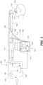
- FIG. 1 shows a breathing circuit according to at least one embodiment, which includes one or more medical tubes.
- Tube is a broad term and is to be given its ordinary and customary meaning to a person of ordinary skill in the art (that is, it is not to be limited to a special or customized meaning) and includes, without limitation, non-cylindrical passageways.
- the breathing circuit incorporates one or more variable-stiffness tubes, which may generally be defined as a tube having distinct stiffness at each end of the tube.
- Such a breathing circuit can be a continuous, variable, or bi-level positive airway pressure (PAP) system or other form of respiratory therapy.
- PAP bi-level positive airway pressure
- Gases can be transported in the circuit of FIG. 1 as follows. Dry gases pass from a ventilator/blower 105 to a humidifier 107, which humidifies the dry gases.
- the humidifier 107 connects to the inlet 109 (the end for receiving humidified gases) of the inspiratory tube 103 via a port 111, thereby supplying humidified gases to the inspiratory tube 103.
- An inspiratory tube is a tube that is configured to deliver breathing gases to a patient, and may be made from a variable-stiffness tube as described in further detail below.
- the gases flow through the inspiratory tube 103 to the outlet 113 (the end for expelling humidified gases), and then to the patient 101 through a patient interface 115 connected to the outlet 113.
- dry gases enter the ventilator/blower 105 through a vent 119.
- a fan 121 can improve gas flow into the ventilator/blower by drawing air or other gases through vent 119.
- the fan 121 can be, for instance, a variable speed fan, where an electronic controller 123 controls the fan speed.
- the function of the electronic controller 123 can be controlled by an electronic master controller 125 in response to inputs from the master controller 125 and a user-set predetermined required value (preset value) of pressure or fan speed via a dial 127.
- the humidifier 107 comprises a humidification chamber 129 containing a volume of water 130 or other suitable humidifying liquid.
- the humidification chamber 129 is removable from the humidifier 107 after use. Removability allows the humidification chamber 129 to be more readily sterilized or disposed.
- the humidification chamber 129 portion of the humidifier 107 can be a unitary construction.
- the body of the humidification chamber 129 can be formed from a non-conductive glass or plastics material.
- the humidification chamber 129 can also include conductive components.
- the humidification chamber 129 can include a highly heat-conductive base (for example, an aluminum base) contacting or associated with a heater plate 131 on the humidifier 107.
- the humidifier 107 may be a standalone humidifier, such as any of the humidifiers in the respiratory humidification range of Fisher & Paykel Healthcare Limited of Auckland, New Zealand.
- Patient interface 115 can be incorporated.
- Patient interface is a broad term and is to be given its ordinary and customary meaning to a person of ordinary skill in the art (that is, it is not to be limited to a special or customized meaning) and includes, without limitation, masks (such as tracheal mask, face masks and nasal masks), cannulas, and nasal pillows.
- a temperature probe 135 can connect to the inspiratory tube 103 near the patient interface 115, or to the patient interface 115. The temperature probe 135 monitors the temperature near or at the patient interface 115.
- a heating filament (not shown) associated with the temperature probe can be used to adjust the temperature of the patient interface 115 and/or inspiratory tube 103 to raise the temperature of the inspiratory tube 103 and/or patient interface 115 above the saturation temperature, thereby reducing the opportunity for unwanted condensation.
- exhaled humidified gases are returned from the patient interface 115 to the ventilator/blower 105 via the expiratory tube 117.
- the expiratory tube 117 can also be a variable-stiffness tube, as described in greater detail below.
- the expiratory tube 117 can also be a medical tube as previously known in the art.
- the expiratory tube 117 can have a temperature probe and/or heating filament, as described above with respect to the inspiratory tube 103, integrated with it to reduce the opportunity for condensation.
- the expiratory tube 117 need not return exhaled gases to the ventilator/blower 105.
- exhaled humidified gases can be passed directly to ambient surroundings or to other ancillary equipment, such as an air scrubber/filter (not shown).
- the expiratory tube is omitted altogether.
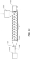
- FIG. 2A shows a longitudinal cross section of example variable-thickness tube 201.
- the medical tube 201 comprises an elongate conduit 203 having a first opening 205, a second opening 207, and a longitudinal axis LA-LA.
- the elongate conduit 203 has a generally cylindrical shape.
- “conduit” is a broad term and is to be given its ordinary and customary meaning to a person of ordinary skill in the art (that is, it is not to be limited to a special or customized meaning) and includes, without limitation, non-cylindrical passageways.
- a lumen 209 extends between the first opening 205 and the second opening 207 along the longitudinal axis LA-LA.
- the conduit 203 is stiffer adjacent the first opening 205 than it is adjacent the second opening 207.
- the conduit 203 comprises a wall 211, extending between the first opening 205 and the second opening 207, and surrounding the lumen 209.
- the wall 211 is stiffer in a first region 213 of the conduit 203 adjacent the first opening 205 than in a second region 215 of the conduit 203 adjacent the second opening 207.
- the wall 211 can be optionally corrugated, or of a corrugate profile. As shown in this example, the corrugation profile can comprise of alternating outer crests (or annular protrusions) and inner troughs (or annular recesses).
- the outer crests can correspond to a location of maximum inner radius and maximum outer radius of the elongate conduit, and the inner troughs can correspond to a location of minimum inner radius and minimum outer radius of the elongate conduit.
- Such corrugations may be of an annular corrugation or spiral corrugation form.
- the wall 211 can be of a smooth or non-corrugated profile.
- the first opening 205 is configured in size and shape to connect to a source of humidified gas, such as a humidifier described above
- the second opening 207 is configured in size and shape to connect to a patient interface.
- one or more ends can be configured to connect to a connection port which facilitates connection to the patient interface and/or humidifier.
- Other configurations can also be desirable.
- the first opening 205 can be configured to connect to a patient interface
- the second opening 207 can be configured to connect to a ventilator/blower, as described above.
- the tube 201 can optionally include one or more conductive (heating or sensing) filaments.
- Optional positions for the filaments are: placed within the lumen, typically in a loose, spiral fashion; placed in close external contact to the tube wall, typically in conjunction with an external sheath to secure the conductive filament(s) in place and prevent heat loss; or embedded in the tube wall.
- the increased stiffness of the tube at one end can lead to better management of condensate by improving "drain back.” Furthermore, the increased stiffness is linked to properties that improve the insulating profile of the wall, such as increased thickness, mass, and/or volume.
- the first end is preferably the humidifier end to better insulate the tube against heat loss where most of the condensation occurs. This configuration also adds stiffness to the tube where it exits the humidifier, so it can maintain a more vertical position for a greater distance, before bending toward the horizontal. In this way, more condensation drains back to the humidifier, rather than entering the breathing tube.
- a thinner tube at the patient end improves flexibility, reduces weight, and improves the comfort of the patient.
- the tubes according to the various embodiments lead to less condensate and also a greater range of ambient conditions where they can be used before condensation build up becomes a substantial issue.
- variable-stiffness tubes described herein can be used as a replacement for tubes previously used in the art, which typically have an average lumen diameter between 10 mm and 30 mm and length ranging between about 1 m and 2.5 m.
- the second region 215 thereof comprises 10% (or about 10%), or 15% (or about 15%) of the total length of the tube 201 (where for example, the total length of the tube 201 is the distance from the first opening 205 to the second opening 207).
- the first region 213 is 0.3-0.7 m (or about 0.3-0.7 m) in length and preferably 0.5 m or thereabout
- the second region 215 is 0.1-0.2 m (or about 0.1-0.2 m) in length and preferably 1.15 m or thereabout
- a third region 221 intermediate the first region 213 and second region 215 is between 1.0-1.5 m in length and preferably 0.15 m or thereabout.
- the first region 213 and second region 215 represent substantial lengths of the tube 201.
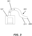
- the stiffness of the first region 213 can be defined in terms of a "drain-back length.”
- the tube 201 when the tube 201 is engaged with a humidifier 107 or other source of humidified gas, the tube 201 is generally upright at the point of engagement.
- the slope of a hypothetical line drawn through the center of the tube 201 is nearly infinite. Without some kind of support holding the tube 201 in this position, the flexibility of the tube 201 naturally causes it to bend at a distance away from the point of engagement.
- the slope of the hypothetical line through the center of the tube 201 gradually decreases as the distance from the point of engagement increases. At a certain distance away from the point of engagement, the slope of the hypothetical line reaches zero.
- the slope of the hypothetical line gradually becomes more negative.
- condensate collecting on the tube's wall 211 surrounding the lumen 209 can theoretically "drain back" into the humidifier 107 under the force of gravity.
- the slope of the hypothetical line is negative, the condensate will theoretically drain away from the humidifier 107.
- the drain-back length 301 can be defined in terms of the distance between the point of connection to a humidifier 107 (or other source of humidity) and the point when the slope of the hypothetical line through the center of the tube 201 is zero.
- the drain-back length 301 is the length of tube 201 measured from the point of connection to a humidifier 107 in which condensate collecting on the wall 211 surrounding the lumen 209 will naturally drain back into the humidifier 107.
- the drain-back length 301 increases. If the first region 213 is less stiff, the drain-back length 301 decreases.
- the drain-back length 301 is 350-400 mm (or about 350-400 mm), e.g., 380 mm (or about 380 mm).
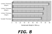
- a study was conducted to assess the effect of stiffness on the ability of the tube 201 to allow condensation on the tube wall 211 to drain back into the humidifier 107.
- a tube 201 with a thick cladding was connected to an AIRVO humidifier manufactured by Fisher & Paykel Healthcare Limited in Auckland, New Zealand.
- the drain-back length was measured to be 380 mm.
- a tube with no cladding was used.
- the drain-back length of 380 mm was replicated using a retort stand to hold the tube in place.
- the AIRVO humidifier was then turned on and run at a flow rate of 15 L/min.
- a small desk fan was placed 40 cm away from the humidifier outlet and turned on to the highest setting. This unrealistic draft condition was imposed to amplify possible condensation.
- Distal to the retort stand the tube was allowed to assume a horizontal position lying on a desk.
- the AIRVO humidifier and fan were left running for 16 hours. After this time, the tube was removed from the AIRVO humidifier, and the tube was weighed.
- condensation forming in this portion of the tube 201 runs back into the humidified gases delivery device.
- Certain embodiments include the realization that forming the tube 201 with a suitable drain-back length 301 provides for this upward extension while obviating the need for a bulky or complex rigid connector.
- several properties can affect the stiffness of the conduit 203. For example, in at least one embodiment, the fact that the conduit 203 is stiffer adjacent the first opening 205 than it is adjacent the second opening 207 results from the wall 211 of the conduit 203 being thicker adjacent the first opening 205 than it is adjacent the second opening 207.
- the first region 213 has an average wall 211 thickness of 0.5-2.0 mm (or about 0.5-2.0 mm), or 1.0-2.0 mm (or about 1.0-2.0 mm), or 1.1-1.6 mm (or about 1.1-1.6 mm), or 1.6 mm (or about 1.6 mm), or 1.58 mm (or about 1.58 mm), or 1.18 mm (or about 1.18 mm).
- the second region 215 has an average wall 211 thickness of 0.1-1.0 mm (or about 0.1-1.0 mm), or 0.1-0.7 mm (or about 0.1-0.7 mm), or 0.1-0.5 mm (or about 0.1-0.5 mm), or 0.2-0.7 mm (or about 0.2-0.7 mm), or 0.3-0.6 mm (or about 0.3-0.6 mm), or 0.30 mm (or about 0.30 mm), 0.33 mm (or about 0.33 mm), 0.37 mm (or about 0.37 mm), 0.50 mm (or about 0.50 mm), 0.53 mm (or about 0.53 mm), 0.54 mm (or about 0.54 mm), or 0.56 mm (or about 0.56 mm).
- a third region 211 intermediate the first region 213 and second region 215 can have an average wall 211 thickness of 0.5-1.0 mm (or about 0.5-1.0 mm), preferably 0.6 mm or thereabout.
- the average wall 211 thickness is at least 25% (or about 25%) greater, at least 100% (or about 100%) greater, or at least 200% (or about 200%) greater in the first region 213 than in the second region 215.
- the ratio of average wall 211 thickness in the first region 213 to the average wall 211 thickness in the second region 221 is 1.5:1-5.5:1 (or about 1.5:1-5.5:1), or 4.5:1-5.0:1 (or about 4.5:1-5.0:1), or 2.0:2.5 (or about 2.0:2.5).
- the ratio can be 4.8:1 (or about 4.8:1), measured at the crests, and 2.2:1 (or about 2.2:1), measured at the troughs.
- the fact that the conduit 203 is stiffer adjacent the first opening 205 than it is adjacent the second opening 207 results from the wall 211 of the conduit 203 having greater mass adjacent the first opening 207 than adjacent the second opening 207.
- the ratio of average wall 211 mass in the first region 213 to the average wall 211 mass of the tube 201 in the second region 215 can be 1.5:1-1.9:1 (or about 1.5:1-1.9:1), or 1.5:1-2:1 (or about 1.5:1-2:1).
- the first region 213 can have an average wall 211 mass of 50-110 g/m (or about 50-110 g/m), or 65-100 g/m (or about 65-100 g/m), or 65-80 g/m (or about 65-80 g/m), or 70 g/m (or about 70 g/m), or 75 g/m (or about 75 g/m).
- the second region 215 can have an average wall 211 mass of 20-50 g/m (or about 20-50 g/m), or 30-50 g/m (or about 30-50 g/m), or 30-45 g/m (or about 30-45 g/m), or 35-45 g/m (or about 35-45 g/m), or 40 g/m (or about 40 g/m), or 42 g/m (or about 42 g/m).
- a third region 221 intermediate the first region 213 and second region 215 can have an average wall 211 mass of 45-65 g/m (or about 45-65 g/m), preferably 50 g/m or thereabout.
- the average wall 211 mass is at least 25% (or about 25%) greater, at least 100% (or about 100%) greater, or at least 200% (or about 200%) greater in the first region 213 than in the second region 215.
- the fact that the conduit 203 is stiffer adjacent the first opening 205 than it is adjacent the second opening 207 results from the wall 211 of the conduit 203 having greater volume adjacent the first opening 207 than adjacent the second opening 207.
- the ratio of average wall 211 volume in the first region 213 to the average wall 211 volume in the second region 215 can be 1.5:1-3.5:1 (or about 1.5:1-3.5:1), or 2.0:1-3.0:1 (or about 2:0:1-3.0:1), or 2.5:1-2.6:1 (or about 2.5:1-2.6:1).
- the first region 213 can have an average wall 211 volume of 1.0-2.0 cm3/cm (or about 1.0-2.0 cm3/cm), or 1.0-1.5 cm3/cm (or about 1.0-1.5 cm3/cm), or 1.20 cm3/cm (or about 1.20 cm3/cm), or 1.17 cm3/cm (or about cm3/cm).
- the second region 215 can have an average wall 211 volume of 0.2-1.0 cm3/cm (or about 0.2-1.0 cm3/cm), or 0.40-0.55 cm3/cm (or about 0.40-0.55 cm3/cm), or 0.45 cm3/cm (or about 0.45 cm3/cm), or 0.50 cm3/cm (or about 0.50 cm3/cm).
- the average wall 211 volume is at least 25% (or about 25%) greater, at least 100% (or about 100%) greater, or at least 200% (or about 200%) greater in the first region 213 than in the second region 215.
- the fact that the conduit 203 is stiffer adjacent the first opening 205 than it is adjacent the second opening 207 results from the wall 211 having a greater flex modulus adjacent the first opening 205 than adjacent the second opening 207.
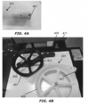
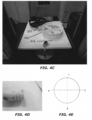
- FIG. 4A-4E illustrates test equipment for measuring the flex modulus of tubes.
- the illustrated equipment comprises a commercially-available Instron machine.
- a plug 401 is inserted into an opening of the tube 201 sample.
- the plug 401 is connected to an arm 403 of test wheel 405.
- the tube 201 is wrapped around the test wheel 405 (which has a diameter of 78mm) and is secured by a support wheel 407 which has a diameter of 75 mm.
- the support wheel 407 touches the tube 201 in order to secure its position. It does not crush the tube 201 sample.
- the location of support wheel 407 is adjusted accordingly by adjusting the position of screws 409 along slots 411 in the supporting frame 413 for the support wheel 407.
- the cord 415 is then pulled at a constant rate of 250 mm per minute for a distance of 100 mm.
- the tensile load on the cord 415 is recorded as a function of distance.
- test is repeated with the tube 201 rotated to each of four orientations about the tube axis (shown in FIGS. 4D and 4E ) to account for asymmetries in the form of the tube 201.
- Testing according to this procedure provides flexure property data for the tube 201.
- Testing a tube 201 with potentially different flex moduli at locations along the tube 201 comprises testing each region of the tube 201 by cutting out the region, mounting the region, and testing according to this procedure.
- the flex modulus is calculated as the gradient of the linear portion of the load versus extension plot created through the test.
- the flex modulus for the test section is the average flex modulus calculated for each of the four orientations.
- FIG. 5A illustrates flexure test data for the four orientations of a section of corrugated tube having a tube weight of 100g/m
- FIG. 5B illustrates flexure test data for the four orientations of a section of corrugated tube having a tube weight of 40g/m.
- FIG. 5C illustrates only the linear portion of the plots of FIG. 5A , with lines of best fit for each orientation of the tube.
- the line of best fit for the tube in a first orientation and has a gradient of 0.3377 N/mm.
- the line of best fit for the tube for a second orientation has a gradient of 0.3652 N/mm.
- the line of best fit for the tube in the third orientation has a gradient of 0.342 N/mm.
- the line of best fit for the tube oriented in the fourth position and has a gradient of 0.3506 N/mm.
- the average gradient, and therefore the flex modulus according to this test calculated for this tube portion is 0.3488 N/mm.
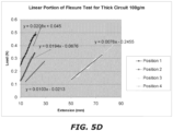
- FIG 5D illustrates an enlarged part of the curves in FIG. 5B , with lines of best fit for each orientation of the tube.
- the line of best fit for the tube in a first orientation has a gradient of 0.0208 N/mm.
- the line of best fit for the tube in a second orientation has a gradient of 0.0194 N/mm.
- the line of best fit for the tube in a third orientation has a gradient of 0.0076 N/mm.
- the line of best fit for the tube oriented in a fourth orientation has a gradient of 0.0103 N/mm.
- the average gradient, and therefore the flex modulus measured according to this test calculated for this tube portion is 0.01452 N/mm.
- the portion of corrugated tube having a tube weight of 40g/m has a test flex modulus of about 0.015 N/mm, while the portion of corrugated tube having a tube weight of 100g/m has a test flex modulus of 0.349 N/mm.
- the flex modulus of the 100g/m sample is more than 20 times the flex modulus of the 40g/m tube.
- the ratio of flex modulus in the first region to that in the second region can be 10:1-250:1 (or about 10:1-250:1), 100:1-220:1 (or about 100:1-220:1), or 170:1-200:1 (or about 170:1-200:1), or 188:1 (or about 188:1), or 185:1 (or about 185:1).
- the average flex modulus is at least 25% (or about 25% greater), at least 100% greater, or at least 200% greater in the first region than in the second region.
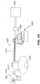
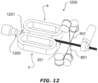
- the system 1001 includes a delivery conduit 1013 that connects between the humidifier chamber 1011 and the patient 1005 peritoneal cavity or surgical site.
- the conduit 1013 is a variable-stiffness tube as described above.
- the conduit 1013 has a first end and second end, the first end being connected to the outlet of the humidifier chamber 1011 and receiving humidified gases from the chamber 1011.
- the second end of the conduit 1013 is placed in the patient 1005 surgical site or peritoneal cavity and humidified insufflation gases travel from the chamber 1011, through the conduit 1013 and into the surgical site to insufflate and expand the surgical site or peritoneal cavity.
- the system also includes a controller (not shown) that regulates the amount of humidity supplied to the gases by controlling the power supplied to the heater base 1009. The controller can also be used to monitor water in the humidifier chamber 1011.
- a smoke evacuation system 1015 is shown leading out of the body cavity of the patient 1005.
- An extruder such as a Welex extruder equipped with a 30-40 mm diameter screw and, typically, a 12-16 mm annular die head with gap of 0.5-1.0mm has been found to be suitable for producing low cost tubes quickly.
- Similar extrusion machines are provided by American Kuhne (Germany), AXON AB Plastics Machinery (Sweden), AMUT (Italy), and Battenfeld (Germany and China).
- a corrugator such as those manufactured and supplied by Unicor ® (Hassfurt, Germany) has been found to be suitable for the corrugation step. Similar machines are provided by OLMAS (Carate Brianza, Italy), Qingdao HUASU Machinery Fabricate Co., Ltd (Qingdao Jiaozhou City, P.R. China), or Top Industry (Chengdu) Co., Ltd. (Chengdu, P.R.of China).
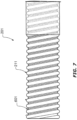
- the molten tube 1109 is passed between a series of rotating molds/blocks on the corrugator after exiting the extruder die head 1111 and is formed into a corrugated tube.
- the molten tube is formed by vacuum applied to the outside of the tube via slots and channels through the blocks and/or pressure applied internally to the tube via an air channel through the center of the extruder die core pin. If internal pressure is applied, a specially shaped long internal rod extending from the die core pin and fitting closely with the inside of the corrugations may be required to prevent air pressure escaping endways along the tube.
- the corrugator speed can be varied to achieve different wall thickness. Slower corrugator speed gives a thicker wall, and faster speed gives a thinner wall.
- the method comprises extruding a tape, wherein a first length of the tape is stiffer that a second length of the tape; spirally winding the extruded tape around a mandrel such that adjacent turns of the extruded tape touch or overlap, thereby forming an elongate conduit having a longitudinal axis, a lumen extending along the longitudinal axis, and a wall surrounding the lumen, wherein the wall is stiffer in a first length of the conduit than in a second length of the conduit.
- the method can also include optionally corrugating the elongate conduit.
- the extrusion process involves mixing or providing of a master batch of extrudate material (i.e. material for extrusion), feeding the master batch to an extrusion die head, extruding the extrudate into a tape.
- a master batch of extrudate material i.e. material for extrusion
- spirally wound conduits can be made with a single helically disposed tape or multiple helically disposed tapes interleaved.
- a reinforcing bead overlays the overlap between turns of tape.
- the bead may provide a helical reinforcement against crushing for the tube and may also provide a source of heat, chemical or mechanical adhesive for fusing or joining the lapped portions of tape.
- a double wall conduit can be constructed by laying additional tape, or portions of the same tape, over the outside, supported on the helical ridge formed by the bead.
- the stiffness of the tube depends upon the stiffness of the tape, and the stiffness of the tube can be adjusted by changing the thickness, mass, volume, flex modulus, etc. of the tape.
- a tube having variable wall thickness along its length may be constructed according to this process by varying the thickness of the tape so that, for example, in a first region, the tape may have a thickness that is greater than in another region, where the thickness may be slightly thinner, and the second region where the thickness may be thinner still.
- Another suitable method for spiral forming comprises extruding a tape having a generally uniform stiffness; spirally winding the extruded tape around a mandrel such that adjacent turns of the extruded tape touch or overlap, thereby forming an elongate conduit having a longitudinal axis, a lumen extending along the longitudinal axis, and a wall surrounding the lumen, wherein the wall is stiffer in a first length of the conduit than in a second length of the conduit.
- the method can includes corrugating the elongate conduit, to provide a conduit having a variable-stiffness wall. For example, the corrugator speed can be varied to achieve different wall thickness. Slower corrugator speed gives a thicker wall, and faster speed gives a thinner wall.
Landscapes
- Health & Medical Sciences (AREA)
- Engineering & Computer Science (AREA)
- Heart & Thoracic Surgery (AREA)
- Life Sciences & Earth Sciences (AREA)
- General Health & Medical Sciences (AREA)
- Biomedical Technology (AREA)
- Pulmonology (AREA)
- Hematology (AREA)
- Veterinary Medicine (AREA)
- Animal Behavior & Ethology (AREA)
- Anesthesiology (AREA)
- Public Health (AREA)
- Emergency Medicine (AREA)
- Mechanical Engineering (AREA)
- Rigid Pipes And Flexible Pipes (AREA)
- Media Introduction/Drainage Providing Device (AREA)
- Infusion, Injection, And Reservoir Apparatuses (AREA)
- Materials For Medical Uses (AREA)
- External Artificial Organs (AREA)
Applications Claiming Priority (3)
| Application Number | Priority Date | Filing Date | Title |
|---|---|---|---|
| US201161547482P | 2011-10-14 | 2011-10-14 | |
| PCT/NZ2012/000184 WO2013055235A1 (en) | 2011-10-14 | 2012-10-12 | Medical tubes and methods of manufacture |
| EP12840138.7A EP2766079B1 (en) | 2011-10-14 | 2012-10-12 | Medical tubes |
Related Parent Applications (1)
| Application Number | Title | Priority Date | Filing Date |
|---|---|---|---|
| EP12840138.7A Division EP2766079B1 (en) | 2011-10-14 | 2012-10-12 | Medical tubes |
Publications (2)
| Publication Number | Publication Date |
|---|---|
| EP4074358A1 EP4074358A1 (en) | 2022-10-19 |
| EP4074358B1 true EP4074358B1 (en) | 2025-03-26 |
Family
ID=48082144
Family Applications (2)
| Application Number | Title | Priority Date | Filing Date |
|---|---|---|---|
| EP22159110.0A Active EP4074358B1 (en) | 2011-10-14 | 2012-10-12 | Medical tubes |
| EP12840138.7A Active EP2766079B1 (en) | 2011-10-14 | 2012-10-12 | Medical tubes |
Family Applications After (1)
| Application Number | Title | Priority Date | Filing Date |
|---|---|---|---|
| EP12840138.7A Active EP2766079B1 (en) | 2011-10-14 | 2012-10-12 | Medical tubes |
Country Status (7)
Families Citing this family (22)
| Publication number | Priority date | Publication date | Assignee | Title |
|---|---|---|---|---|
| AU2003244171B2 (en) | 2002-09-09 | 2007-11-15 | Fisher & Paykel Healthcare Limited | Limb for Breathing Circuit |
| CN108992757B (zh) | 2011-10-14 | 2022-04-12 | 费雪派克医疗保健有限公司 | 医疗管和制造方法 |
| CN104245027B (zh) * | 2012-04-17 | 2017-05-17 | 皇家飞利浦有限公司 | 用于呼吸治疗系统的气体输送导管 |
| EP2657418B1 (en) * | 2012-04-26 | 2015-01-14 | Airbus Operations GmbH | Noise reduction unit for vacuum suction drains |
| CN110025867B (zh) * | 2012-12-04 | 2022-04-08 | 费雪派克医疗保健有限公司 | 医用管以及其制造方法 |
| DE202013103243U1 (de) * | 2013-07-19 | 2014-10-20 | Rehau Ag + Co | Medienleitung, insbesondere zum Transport einer Harnstoff-Wasser-Lösung |
| GB2579322B (en) | 2015-07-24 | 2020-12-02 | Fisher & Paykel Healthcare Ltd | Tracheostomy guard |
| CN109475717A (zh) | 2016-07-21 | 2019-03-15 | 菲舍尔和佩克尔保健有限公司 | 用于呼吸回路的医用管 |
| US10953185B2 (en) * | 2017-03-31 | 2021-03-23 | Koninklijke Philips N.V. | Moisture wicking conduit and system |
| CA3065087A1 (en) * | 2017-05-26 | 2018-11-29 | Fisher & Paykel Healthcare Limited | Neonatal flexible and hybrid medical tubes |
| GB2569802B (en) * | 2017-12-22 | 2021-12-15 | Intersurgical Ag | Medical tubing |
| CN112105410A (zh) * | 2018-01-24 | 2020-12-18 | 菲舍尔和佩克尔保健有限公司 | 用于呼吸回路的医用管 |
| WO2020005772A1 (en) * | 2018-06-25 | 2020-01-02 | Booker Charles Kent | Surface energy enhancing fluid and applications on living tissues |
| USD958968S1 (en) | 2018-11-28 | 2022-07-26 | Fisher & Paykel Healthcare Limited | Breathing tube with mesh |
| WO2020164120A1 (en) * | 2019-02-15 | 2020-08-20 | Vincent Medical (Dong Guan) Manufacturing Co., Ltd. | A breathing circuit having an embedded heating wire and temperature sensor |
| CN110433376A (zh) * | 2019-08-09 | 2019-11-12 | 贾凌 | 一种气道湿化雾化器管道的控温装置 |
| EP4087635A4 (en) * | 2020-01-08 | 2023-09-06 | Giesbrecht, Owen | CLEANABLE RESPIRATORY CIRCUIT |
| EP3861945A1 (en) * | 2020-02-07 | 2021-08-11 | Gyrus ACMI, Inc. d/b/a Olympus Surgical Technologies America | Medical device including flexible shaft with multiple bearings |
| WO2021206568A1 (en) * | 2020-04-09 | 2021-10-14 | Fisher & Paykel Healthcare Limited | A respiratory conduit |
| US20220241568A1 (en) * | 2020-09-10 | 2022-08-04 | Gerard V. Sunnen | Integrated portable apparatus for topical wound therapy, using ambient air for the creation of three bioactive gases that independently and synergistically assist in the resolution of pathogenic dermatological conditions |
| JP2022154079A (ja) * | 2021-03-30 | 2022-10-13 | 福展美科技有限公司 | 呼吸療法においてユーザインタフェースと共に使用される医療用チューブ |
| WO2022246520A1 (en) * | 2021-05-28 | 2022-12-01 | ResMed Pty Ltd | Conduit for use in a respiratory apparatus |
Citations (1)
| Publication number | Priority date | Publication date | Assignee | Title |
|---|---|---|---|---|
| WO2003022342A1 (en) * | 2001-09-13 | 2003-03-20 | Intersurgical Limited | Anti-condensation sheath for breathing tube |
Family Cites Families (46)
| Publication number | Priority date | Publication date | Assignee | Title |
|---|---|---|---|---|
| AT245244B (de) * | 1961-04-07 | 1966-02-25 | Friedrich Hobiger | Verfahren zur Herstellung von Schläuchen mit ungleichen Wandstärken aus thermoplastischem Kunststoff od. dgl. durch Strangpressen und Strangpresse zur Durchführung des Verfahrens |
| US3871373A (en) * | 1972-10-30 | 1975-03-18 | Richard R Jackson | Humidifying gas |
| US4000341A (en) * | 1975-05-23 | 1976-12-28 | Minnesota Mining And Manufacturing Company | Autoclavable, corrugated, respiratory care tubing |
| DE2654001C2 (de) * | 1976-11-27 | 1986-02-06 | Harald 5210 Troisdorf Feuerherm | Vorrichtung zum Herstellen von aus thermoplastischem Kunstoff bestehenden Hohlkörpern |
| US4275724A (en) * | 1979-04-02 | 1981-06-30 | Barry Behrstock | Endotracheal intubation device |
| US5090408A (en) * | 1985-10-18 | 1992-02-25 | Bryan T. Spofford | Transtracheal catheter system and method |
| US4601713A (en) * | 1985-06-11 | 1986-07-22 | Genus Catheter Technologies, Inc. | Variable diameter catheter |
| US5623922A (en) | 1986-09-23 | 1997-04-29 | Smith; Charles A. | Insulated breathing tube |
| US5377670A (en) * | 1986-09-23 | 1995-01-03 | Smith; Charles A. | Insulated breathing tube |
| US5143409A (en) * | 1989-08-30 | 1992-09-01 | Titeflex Corporation | Stress relief device |
| JP2842691B2 (ja) | 1990-02-02 | 1999-01-06 | オーセ プリンテイング システムズ ゲゼルシャフト ミット ベシュレンクテル ハフツング | プリンタまたはコピー機における記録担体の側方位置決め装置 |
| EP0672430A3 (en) * | 1994-03-15 | 1995-12-27 | Fisher & Paykel | Duct for a humidifier. |
| US5848223A (en) * | 1994-05-27 | 1998-12-08 | Steward Plastics, Inc. | Double-walled flexible tubing product with helical support bead and heating conductor and apparatus and method for making |
| DE19805832A1 (de) * | 1998-02-13 | 1999-08-19 | Dyneon Gmbh | Mischungen aus thermoplastischen Fluorpolymeren |
| US6026811A (en) * | 1998-03-12 | 2000-02-22 | Settle; Romaine A. | Protective cover for nasal air supply hose |
| EP1075848B1 (en) | 1999-08-10 | 2005-11-16 | Fisher & Paykel Healthcare Limited | Mouthpiece with bendable extra-oral sealing means |
| WO2001053358A1 (en) * | 2000-01-19 | 2001-07-26 | The Ohio State University Research Foundation | Synthesis of visible light curable (vlc) acid containing polymers |
| BR0102116B1 (pt) * | 2000-05-10 | 2010-09-21 | componente para um membro de circuito de respiração. | |
| US20030132552A1 (en) * | 2000-05-18 | 2003-07-17 | Gamble Jonathan D. | Process for controlling the manufacturing of dimensionally varying tubular members |
| AU1112102A (en) * | 2000-10-16 | 2002-04-29 | Fisher & Paykel Healthcare Ltd | Improvements to apparatus used for the humidification of gases in medical procedures |
| US6895803B2 (en) * | 2000-10-20 | 2005-05-24 | Fisher & Paykel Healthcare Limited | Humidity sensor |
| US6427694B1 (en) * | 2000-11-22 | 2002-08-06 | Mpv-Truma Gesellschaft Fur Medizintechnische Produkte Gmbh | Nasal breathing mask |
| US6926509B2 (en) * | 2002-05-31 | 2005-08-09 | Ndh Medical, Inc. | Apparatus for extruding tubing having a variable wall thickness |
| US7291240B2 (en) | 2002-09-09 | 2007-11-06 | Fisher & Paykel Healthcare Limited | Method of forming a conduit using a wound sacrificial layer |
| US8529719B2 (en) * | 2002-11-15 | 2013-09-10 | Applied Medical Resources Corporation | Method of making medical tubing having variable characteristics using thermal winding |
| US20050165366A1 (en) * | 2004-01-28 | 2005-07-28 | Brustad John R. | Medical tubing having variable characteristics and method of making same |
| US7367364B2 (en) * | 2003-04-08 | 2008-05-06 | Omega Flex, Inc. | Fire retardant jacket for tubing |
| US20050011524A1 (en) * | 2003-07-17 | 2005-01-20 | Marguerite Thomlinson | Nasal interface apparatus |
| EP1778330B1 (en) * | 2004-08-20 | 2020-10-07 | Fisher & Paykel Healthcare Limited | Apparatus for measuring properties of gases supplied to a patient |
| EP1793885B1 (de) * | 2004-09-03 | 2016-09-28 | Löwenstein Medical Technology GmbH + Co. KG | Kunststoffe für medizintechnische geräte |
| CN103463722B (zh) * | 2005-12-15 | 2015-12-09 | 菲舍尔和佩克尔保健有限公司 | 呼吸辅助设备 |
| NZ610731A (en) * | 2006-07-28 | 2015-02-27 | Resmed Ltd | Delivery of respiratory therapy |
| US9855398B2 (en) | 2006-11-08 | 2018-01-02 | Resmed Limited | Humidifier for respiratory apparatus |
| NZ730968A (en) | 2006-11-08 | 2019-01-25 | ResMed Pty Ltd | Conduit for use in a respiratory apparatus |
| US8171935B2 (en) | 2006-11-15 | 2012-05-08 | Vapotherm, Inc. | Nasal cannula with reduced heat loss to reduce rainout |
| AU2008221506B2 (en) * | 2007-09-20 | 2011-01-20 | ResMed Pty Ltd | Retractable Tube for CPAP |
| US8398587B2 (en) | 2008-02-05 | 2013-03-19 | Steerable Instruments B.V.B.A. | Steerable tube |
| AU2009253833A1 (en) * | 2008-06-05 | 2009-12-10 | Resmed Limited | Treatment of respiratory conditions |
| JP2010179025A (ja) | 2009-02-09 | 2010-08-19 | Fujifilm Corp | 内視鏡用可撓管の製造方法 |
| IT1395037B1 (it) * | 2009-08-12 | 2012-09-05 | Covidien Ag | Cartuccia di umidificazione |
| EP2515980B8 (en) * | 2009-12-22 | 2021-05-19 | Fisher & Paykel Healthcare Limited | Components for medical circuits |
| US8978648B2 (en) * | 2010-04-07 | 2015-03-17 | Resmed Limited | Air delivery conduit |
| WO2011149362A1 (en) | 2010-05-25 | 2011-12-01 | Fisher & Paykel Healthcare Limited | Improved breathing tube |
| WO2011162622A1 (en) | 2010-06-22 | 2011-12-29 | Fisher & Paykel Healthcare Limited | Components for medical circuits |
| GB2496569B (en) * | 2010-09-10 | 2014-08-27 | Fisher & Paykel Healthcare Ltd | A component for conveying gases |
| CN108992757B (zh) | 2011-10-14 | 2022-04-12 | 费雪派克医疗保健有限公司 | 医疗管和制造方法 |
-
2012
- 2012-10-12 CN CN201811053334.XA patent/CN108992757B/zh active Active
- 2012-10-12 CA CA3086495A patent/CA3086495A1/en not_active Abandoned
- 2012-10-12 EP EP22159110.0A patent/EP4074358B1/en active Active
- 2012-10-12 CA CA3086509A patent/CA3086509A1/en not_active Withdrawn
- 2012-10-12 EP EP12840138.7A patent/EP2766079B1/en active Active
- 2012-10-12 JP JP2014535687A patent/JP6357101B2/ja active Active
- 2012-10-12 WO PCT/NZ2012/000184 patent/WO2013055235A1/en active Application Filing
- 2012-10-12 US US14/351,344 patent/US10828455B2/en active Active
- 2012-10-12 AU AU2012321401A patent/AU2012321401B2/en active Active
- 2012-10-12 CA CA3086533A patent/CA3086533A1/en not_active Withdrawn
- 2012-10-12 CA CA2852045A patent/CA2852045C/en active Active
- 2012-10-12 CN CN202210728125.0A patent/CN115105707A/zh active Pending
- 2012-10-12 CN CN201811053333.5A patent/CN109045433B/zh active Active
- 2012-10-12 CN CN201280058622.9A patent/CN103987420B/zh active Active
-
2017
- 2017-12-05 AU AU2017272155A patent/AU2017272155B2/en active Active
-
2018
- 2018-06-15 JP JP2018114323A patent/JP6932107B2/ja active Active
-
2020
- 2020-05-26 AU AU2020203451A patent/AU2020203451B2/en active Active
- 2020-09-22 US US17/028,443 patent/US12263307B2/en active Active
-
2021
- 2021-08-17 JP JP2021132531A patent/JP7274541B2/ja active Active
-
2022
- 2022-11-03 AU AU2022263547A patent/AU2022263547B2/en active Active
-
2023
- 2023-05-01 JP JP2023075651A patent/JP2023101520A/ja active Pending
-
2025
- 2025-01-15 US US19/021,650 patent/US20250152899A1/en active Pending
Patent Citations (1)
| Publication number | Priority date | Publication date | Assignee | Title |
|---|---|---|---|---|
| WO2003022342A1 (en) * | 2001-09-13 | 2003-03-20 | Intersurgical Limited | Anti-condensation sheath for breathing tube |
Also Published As
Similar Documents
| Publication | Publication Date | Title |
|---|---|---|
| AU2022263547B2 (en) | Medical tubes and methods of manufacture | |
| US12350874B2 (en) | Component for conveying gases | |
| AU2022204918A1 (en) | A component for conveying gases |
Legal Events
| Date | Code | Title | Description |
|---|---|---|---|
| PUAI | Public reference made under article 153(3) epc to a published international application that has entered the european phase |
Free format text: ORIGINAL CODE: 0009012 |
|
| STAA | Information on the status of an ep patent application or granted ep patent |
Free format text: STATUS: THE APPLICATION HAS BEEN PUBLISHED |
|
| AC | Divisional application: reference to earlier application |
Ref document number: 2766079 Country of ref document: EP Kind code of ref document: P |
|
| AK | Designated contracting states |
Kind code of ref document: A1 Designated state(s): AL AT BE BG CH CY CZ DE DK EE ES FI FR GB GR HR HU IE IS IT LI LT LU LV MC MK MT NL NO PL PT RO RS SE SI SK SM TR |
|
| STAA | Information on the status of an ep patent application or granted ep patent |
Free format text: STATUS: REQUEST FOR EXAMINATION WAS MADE |
|
| 17P | Request for examination filed |
Effective date: 20230417 |
|
| RBV | Designated contracting states (corrected) |
Designated state(s): AL AT BE BG CH CY CZ DE DK EE ES FI FR GB GR HR HU IE IS IT LI LT LU LV MC MK MT NL NO PL PT RO RS SE SI SK SM TR |
|
| P01 | Opt-out of the competence of the unified patent court (upc) registered |
Effective date: 20230526 |
|
| GRAP | Despatch of communication of intention to grant a patent |
Free format text: ORIGINAL CODE: EPIDOSNIGR1 |
|
| STAA | Information on the status of an ep patent application or granted ep patent |
Free format text: STATUS: GRANT OF PATENT IS INTENDED |
|
| INTG | Intention to grant announced |
Effective date: 20240607 |
|
| GRAJ | Information related to disapproval of communication of intention to grant by the applicant or resumption of examination proceedings by the epo deleted |
Free format text: ORIGINAL CODE: EPIDOSDIGR1 |
|
| STAA | Information on the status of an ep patent application or granted ep patent |
Free format text: STATUS: REQUEST FOR EXAMINATION WAS MADE |
|
| GRAP | Despatch of communication of intention to grant a patent |
Free format text: ORIGINAL CODE: EPIDOSNIGR1 |
|
| STAA | Information on the status of an ep patent application or granted ep patent |
Free format text: STATUS: GRANT OF PATENT IS INTENDED |
|
| INTC | Intention to grant announced (deleted) | ||
| INTG | Intention to grant announced |
Effective date: 20241018 |
|
| GRAS | Grant fee paid |
Free format text: ORIGINAL CODE: EPIDOSNIGR3 |
|
| GRAA | (expected) grant |
Free format text: ORIGINAL CODE: 0009210 |
|
| STAA | Information on the status of an ep patent application or granted ep patent |
Free format text: STATUS: THE PATENT HAS BEEN GRANTED |
|
| AC | Divisional application: reference to earlier application |
Ref document number: 2766079 Country of ref document: EP Kind code of ref document: P |
|
| AK | Designated contracting states |
Kind code of ref document: B1 Designated state(s): AL AT BE BG CH CY CZ DE DK EE ES FI FR GB GR HR HU IE IS IT LI LT LU LV MC MK MT NL NO PL PT RO RS SE SI SK SM TR |
|
| REG | Reference to a national code |
Ref country code: GB Ref legal event code: FG4D |
|
| REG | Reference to a national code |
Ref country code: CH Ref legal event code: EP |
|
| REG | Reference to a national code |
Ref country code: DE Ref legal event code: R096 Ref document number: 602012081448 Country of ref document: DE |
|
| REG | Reference to a national code |
Ref country code: IE Ref legal event code: FG4D |
|
| PG25 | Lapsed in a contracting state [announced via postgrant information from national office to epo] |
Ref country code: RS Free format text: LAPSE BECAUSE OF FAILURE TO SUBMIT A TRANSLATION OF THE DESCRIPTION OR TO PAY THE FEE WITHIN THE PRESCRIBED TIME-LIMIT Effective date: 20250626 |
|
| PG25 | Lapsed in a contracting state [announced via postgrant information from national office to epo] |
Ref country code: FI Free format text: LAPSE BECAUSE OF FAILURE TO SUBMIT A TRANSLATION OF THE DESCRIPTION OR TO PAY THE FEE WITHIN THE PRESCRIBED TIME-LIMIT Effective date: 20250326 |
|
| REG | Reference to a national code |
Ref country code: LT Ref legal event code: MG9D |
|
| PG25 | Lapsed in a contracting state [announced via postgrant information from national office to epo] |
Ref country code: NO Free format text: LAPSE BECAUSE OF FAILURE TO SUBMIT A TRANSLATION OF THE DESCRIPTION OR TO PAY THE FEE WITHIN THE PRESCRIBED TIME-LIMIT Effective date: 20250626 |
|
| PG25 | Lapsed in a contracting state [announced via postgrant information from national office to epo] |
Ref country code: HR Free format text: LAPSE BECAUSE OF FAILURE TO SUBMIT A TRANSLATION OF THE DESCRIPTION OR TO PAY THE FEE WITHIN THE PRESCRIBED TIME-LIMIT Effective date: 20250326 |
|
| PG25 | Lapsed in a contracting state [announced via postgrant information from national office to epo] |
Ref country code: LV Free format text: LAPSE BECAUSE OF FAILURE TO SUBMIT A TRANSLATION OF THE DESCRIPTION OR TO PAY THE FEE WITHIN THE PRESCRIBED TIME-LIMIT Effective date: 20250326 |
|
| PG25 | Lapsed in a contracting state [announced via postgrant information from national office to epo] |
Ref country code: GR Free format text: LAPSE BECAUSE OF FAILURE TO SUBMIT A TRANSLATION OF THE DESCRIPTION OR TO PAY THE FEE WITHIN THE PRESCRIBED TIME-LIMIT Effective date: 20250627 Ref country code: BG Free format text: LAPSE BECAUSE OF FAILURE TO SUBMIT A TRANSLATION OF THE DESCRIPTION OR TO PAY THE FEE WITHIN THE PRESCRIBED TIME-LIMIT Effective date: 20250326 |
|
| REG | Reference to a national code |
Ref country code: NL Ref legal event code: MP Effective date: 20250326 |
|
| PG25 | Lapsed in a contracting state [announced via postgrant information from national office to epo] |
Ref country code: NL Free format text: LAPSE BECAUSE OF FAILURE TO SUBMIT A TRANSLATION OF THE DESCRIPTION OR TO PAY THE FEE WITHIN THE PRESCRIBED TIME-LIMIT Effective date: 20250326 |